Article

Breaking the Cyclic Prefix Barrier: Zero-Padding Correlation Enables Centimeter-Accurate LEO Navigation via 5G NR Signals

1
School of Electronic and Information Engineering, Xi’an Jiaotong University, Xi’an 710049, China
2
China Academy of Space Technology (Xi’an), Xi’an 710100, China
3
Space Engineering University, Beijing 101416, China
4
Key Laboratory of Intelligent Space TTC&O (Space Engineering University), Ministry of Education, Beijing 101416, China
5
State Key Laboratory of Astronautic Dynamics, Xi’an Satellite Control Center, Xi’an 710043, China
*
Author to whom correspondence should be addressed.
Remote Sens. 2025, 17(13), 2116; https://doi.org/10.3390/rs17132116
Submission received: 28 April 2025 / Revised: 13 June 2025 / Accepted: 18 June 2025 / Published: 20 June 2025

Abstract

Low Earth orbit (LEO) satellites offer a revolutionary potential for positioning, navigation, and timing (PNT) services due to their stronger signal power and rapid geometric changes compared to traditional global navigation satellite systems (GNSS). However, dedicated LEO navigation systems face high costs, so opportunity navigation based on LEO satellites is a potential solution. This paper presents an orthogonal frequency division multiplexing (OFDM)-based LEO navigation system and analyzes its navigation performance. We use 5G new radio (NR) as the satellite transmitting signal and introduce the NR signal components that can be used for navigation services. The LEO NR system and a novel zero-padding correlation (ZPC) are introduced. This ZPC receiver can eliminate cyclic prefix (CP) and inter-carrier interference, thereby improving tracking accuracy. The power spectral density (PSD) for the NR navigation signal is derived, followed by a comprehensive analysis of tracking accuracy under different NR configurations (bandwidth, spectral allocation, and signal components). An extended Kalman filter (EKF) is proposed to fuse pseudorange and pseudorange rate measurements for real-time positioning. The simulations demonstrate an 80% improvement in ranging precision (3.0–4.5 cm) and 88.3% enhancement in positioning accuracy (5.61 cm) compared to conventional receivers. The proposed ZPC receiver can achieve centimeter-level navigation accuracy. This work comprehensively analyzes the navigation performance of the LEO NR system and provides a reference for LEO PNT design.

1. Introduction

During the past decades, global navigation satellite systems (GNSS) have served as the foundation for positioning, navigation, and timing (PNT) services that are critical for agriculture, industry, and daily life [1]. Existing GNSS satellites are typically deployed in the medium Earth orbit (MEO) to provide extensive signal coverage [2]. Consequently, due to their extremely weak power levels, GNSS signals are highly susceptible to interference and spoofing while suffering severe degradation in urban canyons and indoor environments [3,4].
The burgeoning low Earth orbit (LEO) constellations present a new opportunity to overcome the limitations of existing GNSS and enhance the quality of PNT service [5,6,7]. Numerous studies have demonstrated the advantages of LEO-based PNT services. (1) Compared to the existing MEO GNSS, the received signal power of LEO satellites enhances by 25~30 dB [4,8,9]. (2) Rapid orbital motion of LEO satellites induces faster geometric changes, reducing the convergence time of precise point positioning (PPP) from 30 to just 1 min [10].
Some studies focus on dedicated LEO satellites for PNT services. The first dedicated LEO navigation satellite was the TRANSIT system designed by the US Navy [11]. Luojia-1A, developed by Wuhan University, broadcasts a dual-band ranging signal with its orbital data, significantly improving GNSS positioning performance [12]. The Centispace system, an LEO navigation augmentation system designed for GNSS, operates in the same radio frequency bands as GNSS (L1 1575.42 MHz and L5 1176 MHz) [13]. The Pulsar constellation, designed by Xona Space, not only provides enhanced GNSS services but also offers encrypted signals to support authentication [14]. Furthermore, by retrofitting existing Iridium satellites, the satellite time and location (STL) service aims to provide assured time and location estimates, even in challenging and strongly attenuated environments [15].
The limited coverage of LEO satellites [16] requires massive constellations to ensure continuous navigation services, imposing prohibitively high costs that render dedicated LEO navigation systems economically unfeasible. As most existing LEO constellations are designed for broadband communications [17], integrating navigation functions into communication signals has become a feasible solution. Three multiplexing methodologies are used to integrate communication and navigation: time division multiplexing (TDM), frequency division multiplexing (FDM), and code division multiplexing (CDM) [18]. In TDM, navigation signals are inserted into communication signal as a frame [19,20]; FDM employs binary offset carrier (BOC) modulation to achieve spectral separation between communication and navigation signals [21,22,23,24]; and CDM directly superimposes spread-spectrum navigation signals onto communication waveforms. But these multiplexing approaches inherently introduce mutual interference between communication and navigation signals. This fundamental conflict motivates the exploration of opportunity navigation, which directly leverages original reference signals in communication waveforms as navigation signal [25,26,27].
Due to the spectral efficiency and anti-multipath capabilities [28], orthogonal frequency division multiplexing (OFDM) has been adopted as the core physical modulation method in Starlink [29,30] and 5G NTN networks [31,32] The OFDM-based opportunity navigation is an increasingly vital and attractive paradigm [33,34,35]. Studies in [36,37] investigate the feasibility of OFDM-based positioning; for non-cooperative LEO OFDM signals, cognitive approaches have been adopted for localization [38,39].
However, there are some limitations for LEO OFDM navigation. (1) Cyclic prefixes (CPs) have been universally adopted in OFDM, and they are a part replica of the OFDM signal. These CP signals are used to mitigate inter-symbol interference caused by multipath effects, but no work analyzes their adverse impact on the navigation performance. (2) The OFDM system has reconfigurable bandwidth and spectrum allocation [31]. In addition, the communication signal includes various channels (such as synchronization, broadcast, and reference signals), and numerous signal components can be used for navigation service. These NR and receiver configurations significantly influence their tracking accuracy. But no study systematically evaluated the impact of different configurations and signal components on tracking accuracy. (3) Many works research opportunity navigation based on actual signals from the LEO constellations like Starlink, and the experiment systems are complicated [30,38,39,40,41,42,43,44]. These studies also lack quantitative analyses of error sources, such as clock bias and ionospheric and tropospheric delays. Providing simple, quantitative, and low-cost analysis for LEO navigation research is essential.
This paper builds a simulation system of OFDM opportunity navigation to overcome these limitations. The 5G new radio (NR) is an open communication standard based on OFDM, and it is used as an OFDM signal in the simulation. A novel zero-padding correlation (ZPC) is proposed for the navigation receiver to eliminate interference from cyclic prefixes (CP) and inter-carriers (including communication and reference signals). We derive the power spectral density of NR reference signals and comprehensively analyze how different NR configurations and signal components affect tracking accuracy. Moreover, an extended Kalman filter (EKF) is designed for the LEO position. The experimental results demonstrate an 80% improvement in tracking precision and a 88.3% enhancement in positioning accuracy compared to existing NR receivers. This paper has three contributions:
  • A system architecture for LEO NR opportunity navigation is presented in detail. We design an NR navigation receiver, and the zero-padding correlator (ZPC) is proposed to address the influence of OFDM CP and inter-carrier interference on navigation performance. For the proposed ZPC receiver, all the reference signals in NR can be utilized to provide navigation service.
  • A experiment validates that ZPC eliminates the influence caused by CP and inter-carriers and significantly enhances tracking accuracy. Compared with other works, the ZPC receiver achieves higher tracking accuracy. Moreover, the relationship between the tracking accuracy and NR configurations, including bandwidth, spectrum location, and signal components combination, is rigorously investigated.
  • We discuss the positioning performance of LEO NR based on an EKF, and simulation results show it can achieve centimeter-level accuracy. Additionally, the clock bias and ionospheric and tropospheric effects on positioning performance are quantitatively analyzed.
The remainder of this paper is organized as follows. Section 2 introduces related works. Section 3 details the NR signal model, OFDM modulation, and power spectral density (PSD). Section 4 introduces the LEO NR navigation system and proposes the ZPC receiver and EKF algorithm. Section 5 discusses the advantages of ZPC in tracking accuracy. Section 6 analyzes ZPC’s tracking performance under varying NR and receiver configurations. Section 7 evaluates positioning accuracy via simulations. Section 8 summarize this paper.

2. Related Works

To further explore LEO OFDM-based opportunity navigation, we survey relevant research, including cooperative and non-cooperative, OFDM-based, and LEO navigation.

2.1. Non-Cooperative and Cooperative Opportunity Navigation

Opportunity navigation utilizes existing radio signals, such as cellular communication signals and television broadcast signals, to provide navigation services [45]. Opportunity navigation can be categorized into two paradigms: cooperative and non-cooperative. Non-cooperative navigation typically operates without base station assistance, and the navigation receiver does not subscribe to base stations. Thereby, non-cooperative navigation offers enhanced privacy preservation. However, non-cooperative navigation suffers from several limitations. (1) The transmitter positions are either unknown or low-accuracy, resulting in degraded navigation accuracy. For terrestrial communication base stations, estimating transmitters’ locations requires sophisticated systems and the estimated results often remain unsatisfactory [46,47]. Although third parties may provide LEO satellite ephemerides, their accuracy is low [48,49]. (2) Unauthorized users cannot precisely acquire signal structures [44,50]. (3) Communication signals are not consistently active.
These challenges in non-cooperative navigation can be effectively addressed through the cooperative method [8,25]. For cooperative receivers, precise orbital data and signal structures can be readily obtained from the transmitter, and transmitting signals can be activated on demand according to receiver requirements. These features enhance navigation accuracy, simplify receiver processing, and ensure continuous navigation services [51]. Hence, cooperative opportunity navigation is adopted in this paper.

2.2. OFDM-Based Opportunity Navigation

OFDM has been widely adopted in LTE, 5G NR, and LEO satellites due to its spectral efficiency and multipath resilience. It is a promising modulation scheme for integrated space-air-ground communications [29,30,33,34]. Therefore, OFDM-based opportunity navigation has become a prominent research domain. LTE opportunity navigation focuses on the time-of-arrival (TOA) delay estimation and interference mitigation. Shamaei [52] pioneered theoretical performance bounds for LTE opportunity positioning through joint TOA and direction-of-arrival (DOA) estimation, while Yang [53,54] experimentally characterized the impact of fading environments and antenna ports on TOA estimation. Wang [55] innovatively modeled inter-cell interference as Gaussian perturbations to quantify TOA accuracy degradation. Techniques such as multipath estimating delay lock loop (MEDLL) and synthetic aperture beamforming [56,57,58] have been developed to address multipath challenges. Additionally, channel fingerprint machine learning [59] and differential positioning frameworks [60] are used to achieve meter-level accuracy.
The evolution of 5G NR has further expanded OFDM-based opportunity navigation capabilities. Abdallah [61] explored carrier-phase-based localization by NR signals, whereas Xhafa [62] and Koivisto [63] achieved joint uplink time-difference-of-arrival (UTDoA) and angle-of-arrival (AoA) estimation through antenna arrays. Lapin [64] enhanced multipath robustness via ESPRIT-based joint delay-phase estimation. Tensor-based channel estimation [65], millimeter-wave beam fingerprinting [66], and machine learning-driven TOA estimation systems [67,68] collectively constitute intelligent positioning architectures that enhance both accuracy and operational reliability.
However, the CP is an essential part of OFDM signals, and its influence on navigation performance is seldom addressed in these existing studies. Furthermore, the relationship between navigation performance and OFDM configurations remains largely unexplored.

2.3. LEO Opportunity Navigation

The burgeoning development of LEO satellites provides new opportunities for opportunity navigation. Khalife [41] pioneered the feasibility verification of Starlink positioning using carrier-phase observations, establishing a framework for LEO-based opportunity navigation. Building upon this, an efficient integer ambiguity resolution algorithm was developed via LEO differential carrier-phase processing [69]. While Doppler frequency can offer alternative navigation solutions, its tracking accuracy remains constrained [40,42,43,44]. Signal coginitvie methodology is proposed to identify configurations of Starlink’s OFDM signal [30,38]. Moreover, Kozhaya [70] achieved positioning through blind estimation of OneWeb constellation beacons, whereas Zhao [71] enhanced navigation robustness by fusing Doppler measurements from Iridium NEXT and Orbcomm constellations. Fundamental research investigates the impact of LEO satellite oscillator stability on navigation performance [72]. The differential Doppler positioning method is proposed to improve navigation accuracy for orbit-unknown LEO satellites [73].
However, the existing works rarely quantitatively evaluate the impact of different error sources, such as clock bias, ionosphere, and tropospheric delay, on navigation performance. This paper assumes that the LEO constellation transmits NR signals to quantitatively analyze the error source’s impact on opportunity navigation performance. The experimental results provide critical insights to future LEO PNT services.

3. Signal Model

This section first introduces the downlink physical channels of 5G NR, emphasizing the signal components that can be used in opportunity navigation. Subsequently, the OFDM modulation with CP is elaborated. The power spectral density (PSD) of the NR reference signal is derived, serving as the foundation for tracking performance analysis.

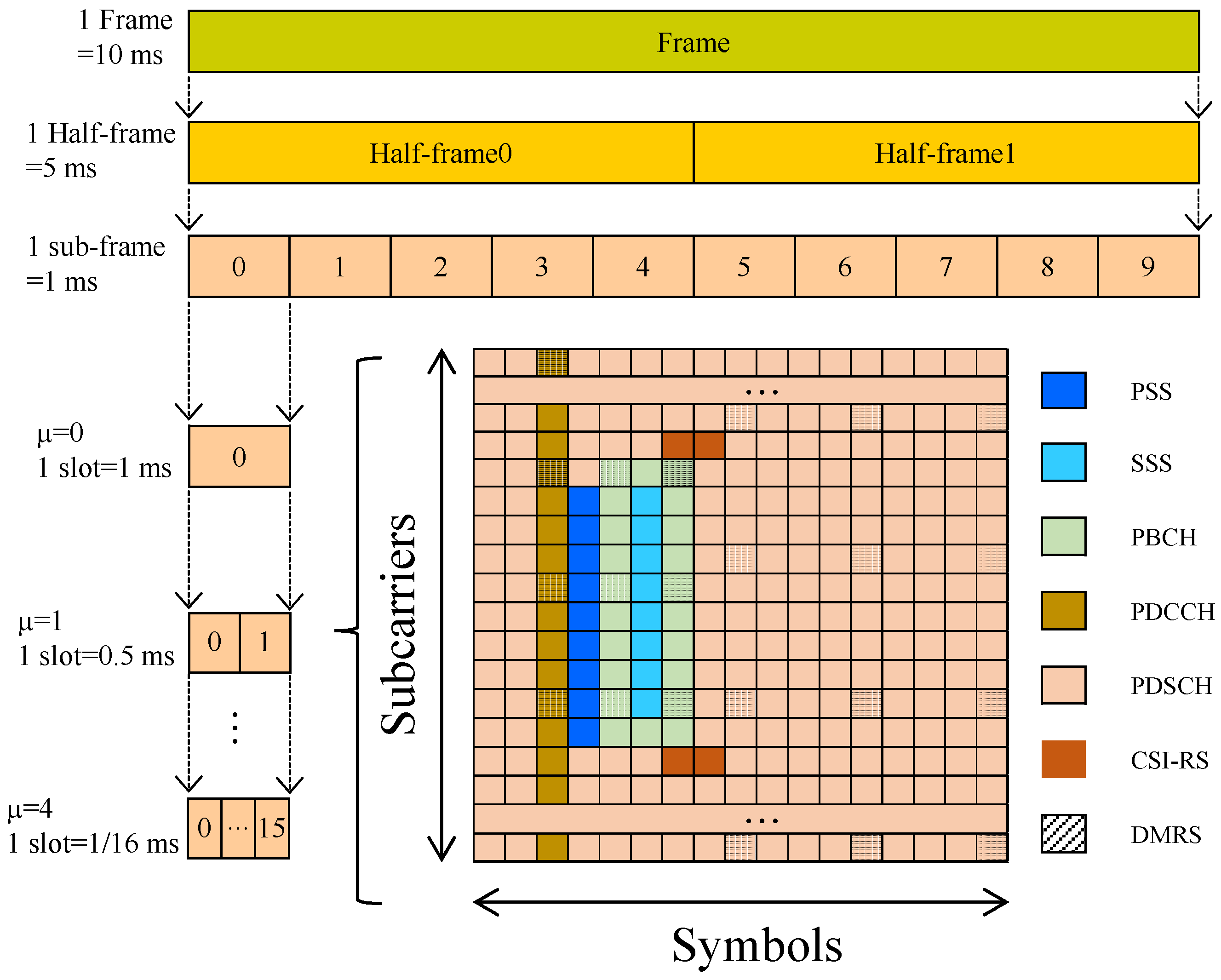
3.1. NR Signal Components

NR specifies different physical channels to utilize radio resources fully [31]. As shown in Figure 1, an NR frame lasts 10 ms and consists of 10 subframes, each lasting 1 ms. Furthermore, each subframe is divided into 2 μ slots and numerology μ { 0 , , 4 } is an NR configuration parameter. Every slot contains 14 (normal CP) or 12 (extended CP) symbols and the subcarrier spacing follows Δ f = 2 μ · 15 kHz. The resource grid further illustrates the allocation of NR physical channels. Each resource element (RE) in the resource grid carries a modulation symbol c n , k , where n and k denote the symbol and subcarrier indices, respectively. These modulation symbols c n , k , obtained from higher-layer signaling, can be categorized into two types: (1) unknown communication data and (2) predefined reference signals or predictable broadcast signals. The latter category can serve as navigation signals.
NR downlink signals conclude multiple physical channels: a synchronization signal and physical broadcast channel (SSB), physical downlink shared channel (PDSCH), physical downlink control channel (PDCCH), and channel state information reference signal (CSI-RS). The SSB facilitates synchronization of user equipment (UE) and provides system message broadcasting. It comprises three signal components: primary synchronization signal (PSS), secondary synchronization signal (SSS), and physical broadcast channel (PBCH). In the time domain, the SSB occupies four OFDM symbols with specific allocation: one for PSS, one for SSS, and two for PBCH. Its transmission periodicity is configurable with options { 5 , 10 , 20 , 40 , 80 , 160 } ms. Both PSS and SSS are m-sequences and their combination uniquely determines the physical layer cell identity (PCI):
P C I = N ID SSS × 3 + N ID PSS
where N ID PSS { 0 , 1 , 2 } denotes the PSS sequence index, and N ID SSS { 0 , 1 , , 335 } represents the SSS sequence index. The PSS and SSS are fixed for transmitters and can be used for navigation service.
The PBCH comprises a master information block (MIB) and demodulation reference signals (DMRS). UE uses the DMRS, with predefined positions and content, for channel estimation. The MIB carries system information about the base station: system frame number (SFN), subcarrier spacing configurations, subcarrier offset parameters, and PDCCH configurations. The SFN increases over time, and other MIB parameters typically remain static. To enhance interference resistance, the MIB undergoes polar coding followed by scrambling. As a consequence, the coded MIB signal is time-varying. Nevertheless, cooperative receivers can effectively estimate these dynamic MIB components through predefined protocol specifications. Due to the predictable property, the entire SSB signal can serve as a local replica signal for navigation receivers.
PDCCH dynamically schedules uplink and downlink radio transmission resources. The downlink control information (DCI) within PDCCH randomly varies according to service requirements. Apart from DCI, PDCCH also contains DMRS, which is used for channel estimation. PDCCH’s DMRS are predetermined; thus, it can be used for navigation.
PDSCH carries downlink communication data. Its time-frequency resources are flexibly allocated according to service demands. To optimize spectral efficiency, NR allocates most resource grid elements to PDSCH. Beyond random communication data, PDSCH also incorporates fixed DMRS for channel estimation. Once PDSCH is configured, the DMRS is deterministic, allowing it for navigation service.
CSI-RS in NR system is dynamically configured by base station according to communication scenarios. UE measures its power to evaluate the wireless channel quality. This protocol-defined determinism signal can be used for navigation.
5G NR employs an ultra-lean transmission paradigm: Only SSB maintains periodic transmission, while other physical channels are transmitted on demand. SSB, CSI-RS, and DMRS embedded in PDSCH/PDCCH are predictable for the receiver and can be used as a local replica signal in NR navigation receiver. All these predictable navigation signals are referred to as reference signals for brevity in the following paper. Based on the reference signal, time delays between the transmitter and receiver can be estimated through code tracking loops to provide PNT service.

3.2. OFDM Modulation

OFDM combines multiple orthogonal narrowband subcarriers into a single wideband signal and it is a core modulation technology for 5G NR systems. Consider an OFDM signal containing K subcarriers with subcarrier spacing of Δ f . For modulation symbol c n , k , the useful OFDM symbol s u ( t ) is expressed as
s u ( t ) = 1 K k = K / 2 K / 2 1 c n , k e j 2 π k Δ f t u T u ( t )
where T u = 1 / Δ f represents the useful symbol duration. This paper employs 1024 subcarriers with a subcarrier spacing of 15 kHz. The rectangular window function u T ( t ) is defined as
u T = 1 ,   0 t < T 0 ,   others
The cyclic prefix (CP) is adopted in the NR system to mitigate inter-symbol interference (ISI) caused by the multipath. CP is a copy of OFDM symbol:
s g ( t ) = 1 K k = K / 2 K / 2 1 c n , k e j 2 π k Δ f t u T g ( t )
where T g denotes the CP duration and is determined by maximum multipath delay.
CP is appended at the beginning of the useful OFDM symbol and the complete time-domain representation of an OFDM symbol with CP is given by
s sym ( t ) = 1 K k = K / 2 K / 2 1 c n , k e j ( 2 π k Δ f t ) u T sym ( t )
where T sym = T u + T g is the duration of total OFDM with CP.

3.3. PSD of NR Reference Signal

The PSD of navigation signals enables the quantitative analysis of tracking accuracy and anti-jamming capability, serving as a critical tool for navigation performance evaluation [74]. According to the NR signal model, reference signals are distributed across subcarriers and are part of the NR signal. ZPC ensures orthogonality between reference signals on different subcarriers while eliminating interference caused by the CP and inter-carrier. Therefore, when the correlation integration period is sufficiently long, the PSD of the NR reference signal can be expressed as the summation of the PSDs of all individual subcarrier reference signals:
G RS ( f ) = 1 N RS ( n , k ) Ω G n , k ( f )
where N RS and Ω denotes the total number and location set of the reference signal in an OFDM resource grid, respectively. G n , k ( f ) represents the PSD of the subcarrier reference signal at the n-th symbol and k-th subcarrier. Its corresponding time-domain signal s n , k ( t ) comprises the modulation symbol c n , k multiplied by a complex exponential (subcarrier waveform):
s n , k ( t ) = c n , k e j 2 π k Δ f t u T ( t ) = c n , k p k ( t )
where p k ( t ) denotes the pulse shaping waveform of the k-th subcarrier.
For the subcarrier reference signal, its PSD G n , k ( f ) can be derived from the PSD G PRN ( f ) of the modulation symbol c n , k and the spectrum P k ( f ) of the subcarrier waveform [75]:
G k ( f ) = 1 T u P k ( f ) 2 G PRN ( f )
where P k ( f ) is the Fourier transform of the subcarrier’s pulse shaping waveform:
P k ( f ) = F T p k ( t ) = T u e j π ( f f k ) T u sinc ( f f k ) T u
where f k = k Δ f represents the k-th subcarrier frequency.
The modulation symbol c n , k of the reference signal can be regarded as an ideal pseudo-random sequence (PRN), and its PSD remains constant at unity:
G PRN ( f ) = 1
This paper uses a default NR and receiver configuration as listed in Table 1. Its PSD curve is illustrated in Figure 2. The PSD of the NR reference signal exhibits multiple spectral peaks at corresponding frequencies. Between these peaks, spectral notches appear due to the absence of a subcarrier reference signal. NR parameters can adjust the number and location of PSD peaks. Hence, the NR parameters determine its tracking performance.

4. NR Navigation System

This section presents the system block diagram of the NR transmitter and navigation receiver. We give a detailed introduction to the receiver tracking loop. A novel correlation integration scheme is proposed to avoid the interference caused by the CP and inter-carrier. Based on the tracking loop, an extended Kalman filter (EKF) is proposed to realize LEO NR positioning.

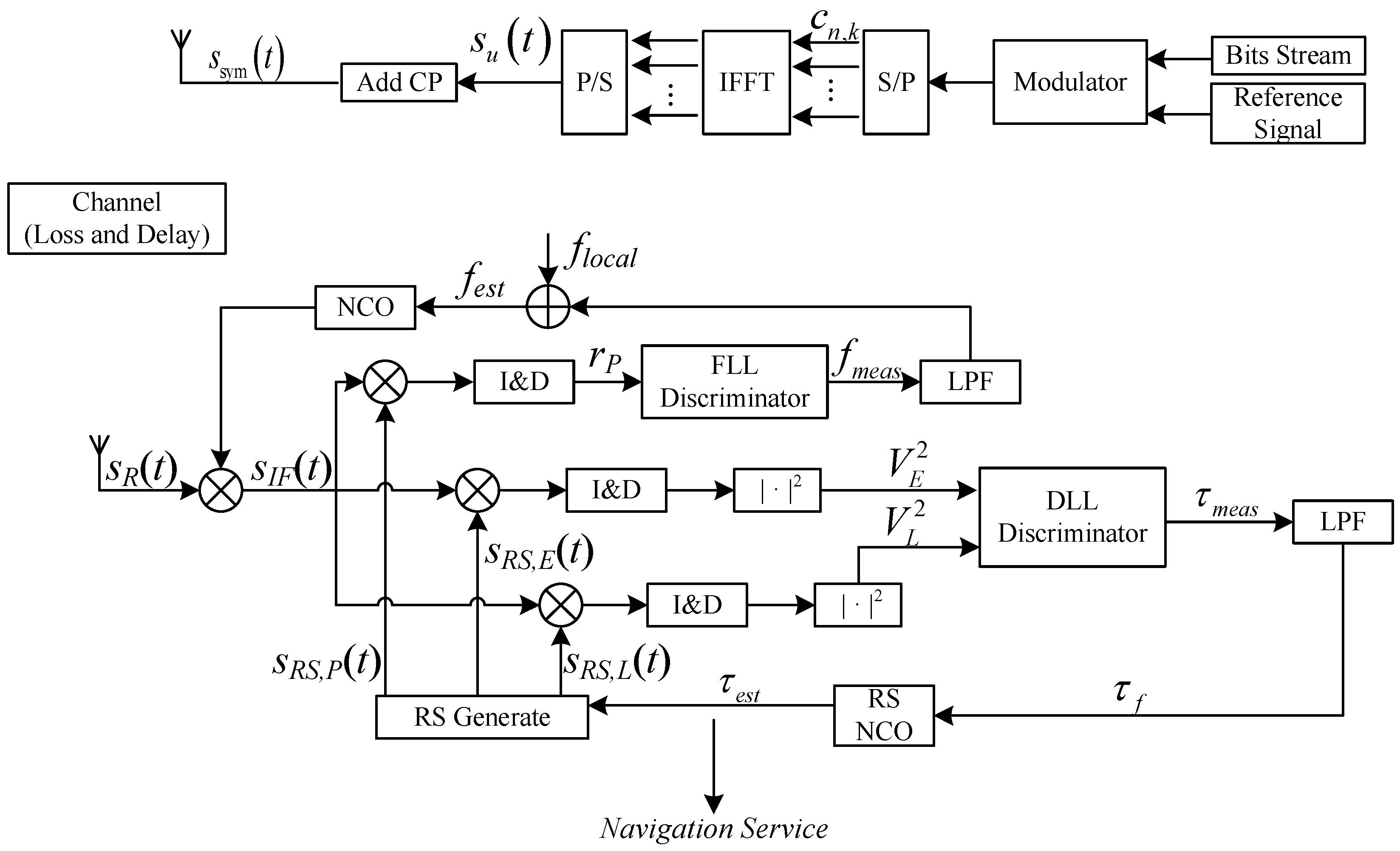
4.1. Transmitting and Reception System Block Diagram

As illustrated in Figure 3, an NR opportunity navigation system comprises three components: an NR signal transmitter, wireless channel, and navigation receiver.
We first introduce the NR transmitter, whose physical layer is similar to the OFDM system. According to NR protocol [31], the higher layer of the base station generates a reference signal and random downlink bit streams. These bit streams undergo digital modulation (e.g., QAM or 16QAM), followed by resource grid mapping. As a result, the serial data streams are transformed to parallel modulation symbols c n , k . OFDM modulation is implemented via inverse fast Fourier transform (IFFT), converting parallel signals to serial waveforms to generate the useful modulated signal s u ( t ) . The cyclic prefix is subsequently appended on useful signal s u ( t ) to form the final transmitted waveform s sym ( t ) (the frequency up and down conversions are omitted). OFDM signals experience amplitude attenuation and time delay through the wireless propagation channel. For LEO satellite signals, additional Doppler frequency shift occurs due to relative motion between satellites and receivers.
The architecture of the NR navigation receiver has an analogous process flow to conventional GNSS receivers. First, the received NR signal is mixed with a local carrier to generate an intermediate-frequency (IF) signal:
s IF ( t ) = Re s R ( t ) e j 2 π f local t = s RS ( t ) + s COM ( t ) e j 2 π f e t + φ e
where f local denotes the local carrier frequency, and f e and φ e represent the frequency and phase offset of the IF signal, respectively. s C O M ( t ) and s R S ( t ) denote the communication data and navigation-available reference signal, respectively. The s C O M ( t ) may influence the navigation performance, and this influence should be avoided as much as possible for the navigation receiver.
The NR receiver consists of two core processing loops: (1) a delay-locked loop (DLL) for code delay estimation using the non-coherent early-late processor (NELP); and (2) a frequency-locked loop (FLL) dedicated to estimating carrier frequency offset. The DLL and FLL exhibit functional complementarity in signal tracking: the DLL eliminates transmission delays by adjusting the phase of the local replica signal, while the FLL maintains carrier synchronization by compensating frequency offset.
The NELP employs three parallel processing branches with relative delays τ (prompt), τ d (early), and τ + d (late), where d specifies the correlator spacing. In the early branch, the local replica reference signal s RS , E ( t ) correlates with the received IF signal. Then, the correlation results are sent to the integrate and dump (I&D) filter and generate correlation amplitude V E :
V E = 0 T coh s IF ( t ) s RS , E * ( t ) d t = R E ( τ ) sinc f e T coh + n COR
where T coh represents the duration of correlation integration. n COR quantifies the interference caused by the CP and inter-carrier. Compared with the traditional GNSS receiver, the CP and inter-carrier communication data significantly impact DLL accuracy. An interference elimination method is proposed in the following subsection.
Similarly, the correlation amplitude V L of the delayed branch can be obtained. The time delay of the received signal can be measured by utilizing V E and V L :
τ meas = K RS V E 2 V L 2 V E 2 + V L 2
where K RS denotes the normalization parameter of the time delay discriminator, derived from the S-curve [2].
To avoid the noise interference and achieve stable tracking time delay, a second-order DLL tracking loop is utilized and it contains a first-order filter [2]:
τ f = τ f , pre + ω n · 1.414 τ meas τ meas , pre + T coh 2 ω n 2 τ meas + τ meas , pre
where τ meas , pre and τ f , pre represent the measured and filtered delay from the previous integration period, respectively. The natural frequency ω n critically affects the tracking accuracy and dynamic response of the NELP. ω n is calculated by the DLL noise bandwidth B L , DLL :
ω n = B L , DLL 0.53
Next, the time delay estimate τ est is derived according to the previous estimate τ est , pre and the filter output τ f :
τ est = τ est , pre + T coh · τ f
FLL operates on the prompt branch, and the frequency offset f e of the received signal is measured according to the phase change. The phase can be obtained from correlation value r P , which is integrated correlation between the IF signal s I F ( t ) and local replica signal:
r P = 0 T coh s IF ( t ) s RS , P * ( t ) d t = 0 T coh s RS ( t ) + s COM ( t ) e j ( 2 π f I t + φ ) s RS , P * ( t ) d t = R P ( τ ) sinc ( f e T coh ) e j φ + n COR
When the correlation noise n COR is negligible, the phase variation between consecutive integration periods becomes measurable:
r P r P , pre ¯ = | r P | | r P , pre | e j [ φ φ pre ]
where r P , pre and φ pre denote the correlation value and phase offset in previous integration period, respectively.
Hence, the frequency offset is calculated as follows:
f meas = arg r P r P , pre ¯ 2 π T coh
Like DLL, the FLL employs a low-pass filter to eliminate high-frequency noise from f meas . The filtered output updates the local carrier frequency f local to stably track the frequency of the received signal.
Different from the conventional communication receiver, the time-delay configuration of the local replica signal is a new requirement for the NR opportunity navigation receiver. The total delay τ decomposes into integer and fractional components relative to the sampling interval T s :
τ = ( τ int + τ frac ) T s
Integer delay τ int is implemented through discrete signal shifting, while fractional delay τ frac is achieved by precise phase adjustment of subcarriers. For example, the k-th subcarrier accomplishes early and late phase shifts τ frac by multiplying modulated symbol c n , k with complex exponential functions:
c n , k , E = c n , k e j 2 π k τ frac / K c n , k , L = c n , k e j 2 π k τ frac / K

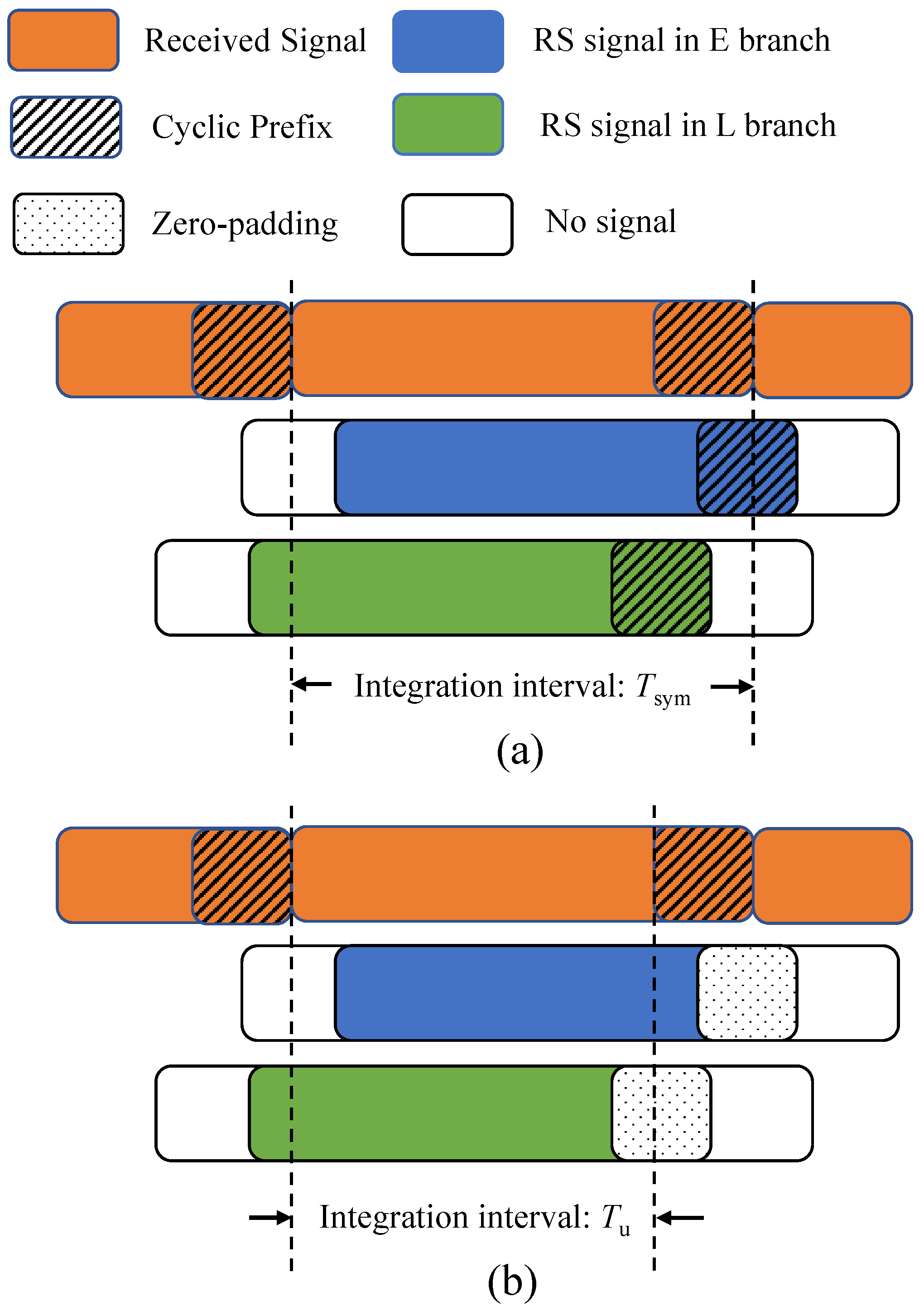
4.2. Interference-Free Correlation: ZPC

First, we introduce the orthogonality condition of OFDM subcarriers: Subcarriers with different frequencies are integrated within a useful symbol period T u , i.e.,:
0 T u c n , k c m , l * e j 2 π k Δ f t e j 2 π l Δ f t d t = 0 , k l T u c n , k c m , k * , k = l
However, NR base stations append cyclic prefixes after OFDM modulation to prevent ISI. The CP extends the symbol duration to T sym . There exists interference when directly correlating OFDM signals containing CP, as depicted in Figure 4a; in other words, cross-correlation between different subcarriers becomes non-zero:
0 T sym c n , k c m , l * e j 2 π k Δ f t e j 2 π l Δ f t d t 0 , k l
Using T sym as the integration duration breaks subcarriers’ orthogonality and induces mutual interference, degrading NR DLL tracking accuracy.
This paper proposes an interference-free correlation: zero-padding correlation (ZPC). As depicted in Figure 4b, the ZPC process involves two aspects: (1) For every OFDM symbol, confining the integration duration to T u preserves subcarrier orthogonality, ensuring that integration between different subcarriers equals zero; and (2) zero-padding the cyclic prefix (CP) intervals effectively eliminates intersymbol interference (ISI). The proposed correlation method preserves subcarrier orthogonality while eliminating the influence of CP and communication data.

4.3. EKF for LEO Navigation

The extended Kalman filter (EKF) is a nonlinear estimation technique and demonstrates particular efficacy in handling the real-time positioning of GNSS navigation receivers [2]. To ensure compatibility with subsequent research, the receiver’s state vector incorporates position, velocity, and clock error parameters:
x ( k ) = r ( k ) , r ˙ ( k ) , δ t ( k ) , δ t ˙ ( k ) T
where r ( k ) = [ x ( k ) , y ( k ) , z ( k ) ] denotes the receiver position at epoch k in Earth-centered, Earth-fixed (ECEF) coordinates, and r ˙ ( k ) represents receiver’s velocity. δ t and δ t ˙ are the receiver’s clock bias and drift rate, respectively.
The system dynamic model is constructed based on receiver motion characteristics:
x ( k + 1 ) = F x ( k ) + w ( k )
where F is the state transition matrix and its definition is as follows:
F = I 3 I 3 τ s 0 3 , 1 0 3 , 1 0 3 I 3 0 3 , 1 0 3 , 1 0 1 , 3 0 1 , 3 1 0 0 1 , 3 0 1 , 3 0 1
where τ s denotes the EKF state propagation interval, equal to the coherent integration duration T coh in this study. I n represents an n × n identity matrix, while 0 m × n indicates an m × n zero matrix.
w ( k ) is the process noise vector and its covariance matrix Q models system uncertainties:
Q = 1 3 S a τ s 3 1 2 S a τ s 2 0 3 , 1 0 3 , 1 1 2 S a τ s 2 S a τ s 0 3 , 1 0 3 , 1 0 1 , 3 0 1 , 3 S c ϕ τ s + 1 3 S c f τ s 3 1 2 S c f τ s 2 0 1 , 3 0 1 , 3 1 2 S c f τ s 2 S c f τ s
where S a denotes the PSD vector of receiver acceleration in ECEF coordinates, S c f represents clock frequency drift PSD, and S c ϕ corresponds to clock phase noise PSD. In this paper, S a , S c f , and S c ϕ are, respectively, set to diag(10, 10, 10), 1, and 1. Hence, Q remains constant for specified motion states.
The pseudorange and pseudorange rate are used as observations in this paper, and these observations are measured by the DLL and FLL, respectively. In addition to real geometric distance and velocity, these measurements also contain various error components. For i-th LEO satellite, its pseudorange measurement ρ i ( k ) can be expressed as
ρ i ( k ) = d i ( k ) + c δ t ( k ) + δ t sat , i ( k ) + I i ( k ) + T i ( k ) + ε i ( k )
where d i ( k ) = r s , i ( k ) r ( k ) denotes the true geometric distance between receiver and satellite, with r s , i ( k ) representing the satellite’s ECEF position coordinates. c denotes the speed of light while δ t ( k ) and δ t sat , i ( k ) correspond to receiver and satellite clock offsets, respectively. The ionospheric and tropospheric delays are modeled as I i ( k ) and T i ( k ) , while ε i ( k ) is the ranging measurement error caused by receiver noise.
The pseudorange rate ρ ˙ i ( k ) , measured from FLL, incorporates the satellite-receiver relative velocity r ˙ i ( k ) and receiver’s clock drift δ ˙ t ( k ) :
ρ ˙ i ( k ) = r ˙ i ( k ) + c δ ˙ t ( k ) + ε v , i ( k )
where ε v , i ( k ) represents the velocity measurement error.
Assuming an LEO NR navigation receiver tracking N satellites, the augmented observation vector ρ ( k ) contains all the pseudorange and pseudorange rate measurements, i.e.,:
ρ ( k ) = ρ 1 ( k ) , , ρ N ( k ) , ρ ˙ 1 ( k ) , , ρ ˙ N ( k ) T
Therefore, the receiver’s tracking loop provides 2 N observations for estimating eight state parameters, establishing an overdetermined system when N > 4 .
The nonlinear observation equation is formulated as
ρ ( k ) = h x ( k ) + v k
where h ( · ) denotes the pseudorange and pseudorange rate measurement function, and v k = ε 1 ( k ) , ε 2 ( k ) , , ε N ( k ) , ε v , 1 ( k ) , ε v , 2 ( k ) , , ε v , N ( k ) represents observation noise. Its covariance matrix R k characterizes the measurement noise:
R k = E v k v k T
R k has a close relationship with the carrier-to-noise ratio and is acquired according to measured noise.
EKF uses the Jacobian matrix H k to linearize the observation model, and it is the partial derivative of the measurement function to the state vector:
H k = h ( x ( k ) ) x ( k )
This matrix quantifies the sensitivity of observations to variations in receiver position, velocity, and clock bias parameters.
Moreover, the covariance matrix P k characterizes the estimation accuracy of the state vector, and its definition is as follows:
P k = E ( x ( k ) x ^ ( k ) ) ( x ( k ) x ^ ( k ) ) T
where x ( k ) and x ^ ( k ) represent the true states and estimated states, respectively.
Figure 5 illustrates the EKF’s update process, which contains prediction and correction modules. At the beginning of the EKF update, two initial parameters are required: (1) initial state vector x ( 0 ) , obtained via least-squares positioning using first-epoch observations; and (2) initial covariance matrix P ( 0 ) , evaluated by the uncertainties in position, velocity, and clock ambiguity.
In EKF, iterations update execute recursive prediction-correction cycles: In the prediction phase, the filter propagates the state estimate x ^ ( k + 1 ) and covariance P ( k + 1 ) from x ^ ( k ) and P ( k ) by using the system dynamics model. Then, the correction phase refines these predictions through observation vector ρ ( k ) and Kalman gain matrix K k :
K k = P k H k T ( H k P k H k T + R k ) 1
The updated state estimate and covariance are as follows:
x ^ ( k ) = x ^ ( k ) + K k ( ρ ( k ) h ( x ^ ( k ) ) )
P ( k ) = ( I K k H k ) P k
This closed-loop EKF outputs real-time navigation solutions while maintaining an optimal balance between model predictions and sensor measurements.

5. Improvement of ZPC Tracking Performance

This section validates the interference-free property of ZPC and compares ZPC with other works in tracking performance. The experiment results demonstrate the improvement of ZPC tracking accuracy and its advantages.

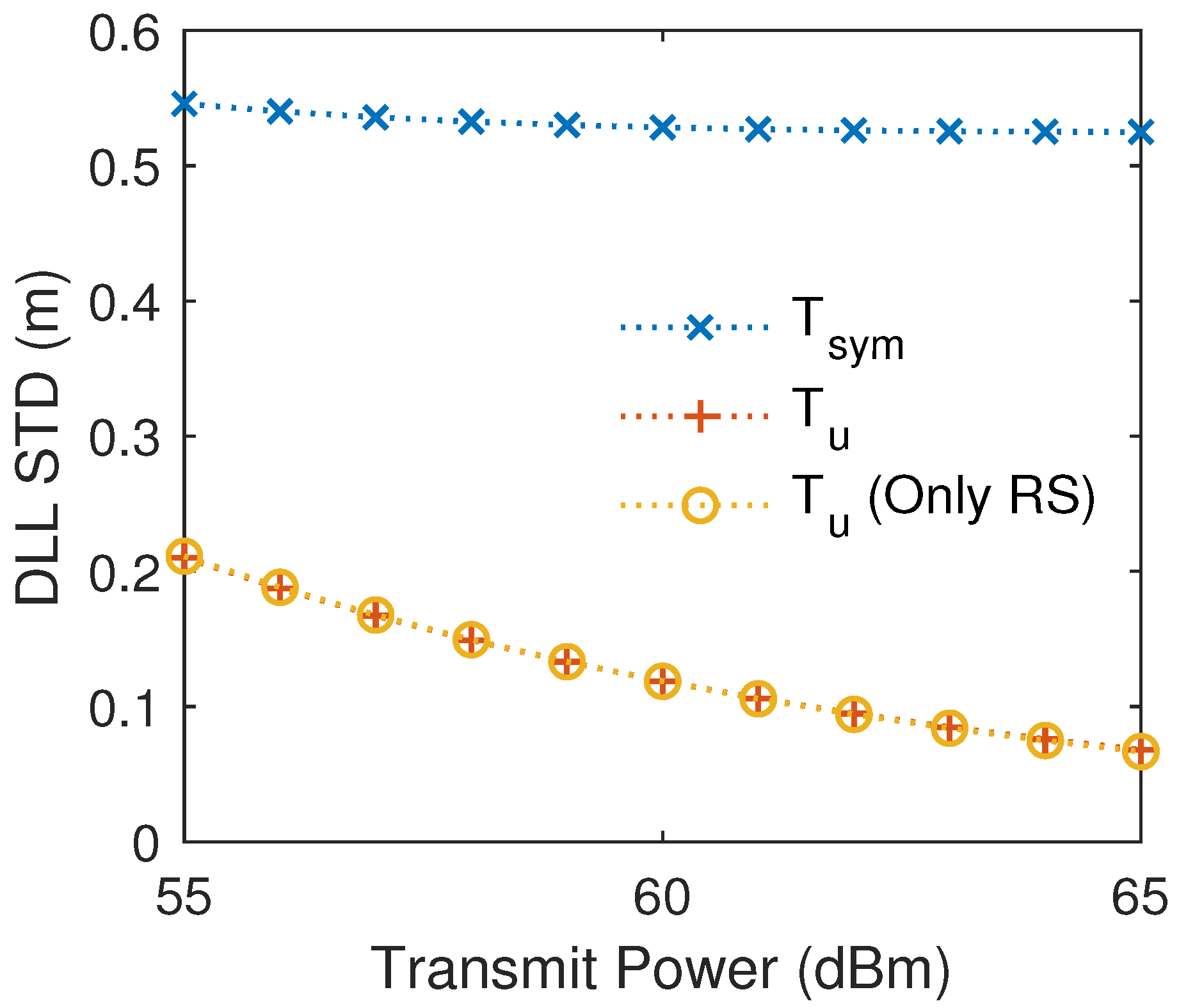
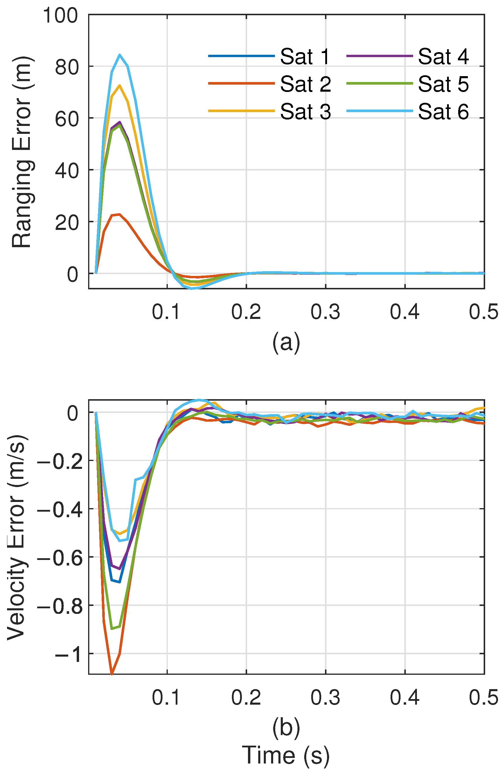
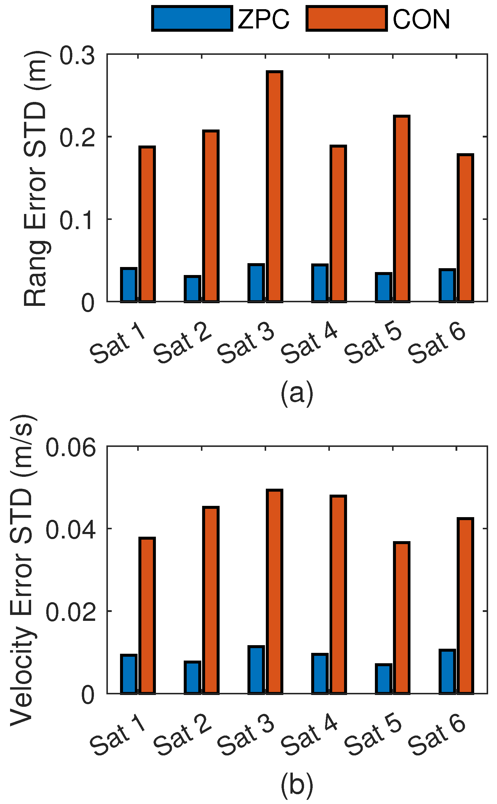
5.1. Validate the ZPC’s Interference-Free Property

An experiment is proposed to demonstrate the ZPC’s interference-free property, which improves the tracking accuracy. There are three configurations in the experiments. (1) The received signal is a conventional NR signal containing both reference signals and unknown communication data. The local replica signal has a CP and its integration duration is T sym . (2) The input signal is the same as (1). Implementing ZPC utilizes a zero-padded local replica signal with a T u integration duration. (3) The received signal only contains the reference signal without communication data, and the receiver uses ZPC. The tracking accuracy of DLL with different configurations is plotted in Figure 6. Comparative results reveal two critical findings: First, the ZPC configuration (red curve) achieves significantly higher tracking accuracy than conventional CP-based processing with duration T sym (blue curve). Because the CP introduces interference to the subcarriers’ orthogonality when the integrated duration is T sym , the subcarrier maintains orthogonality when the ZPC is adopted (the integrated duration is T u ). ZPC significantly eliminates interference caused by the CP and inter-carriers, thereby improving tracking accuracy. Second, configurations (2) and (3) have identical DLL standard deviation (STD) curves, which confirms their same tracking performance. This indicates that the NR communication signal in other carriers has no interference on the DLL when using ZPC. The reason is that ZPC maintains subcarrier orthogonality through optimized integration window selection and zero-padding CP. Overall, ZPC ensures the orthogonality and serves as an interference-free correlation mechanism, effectively eliminating the influence of the CP and inter-carriers while significantly enhancing tracking accuracy.

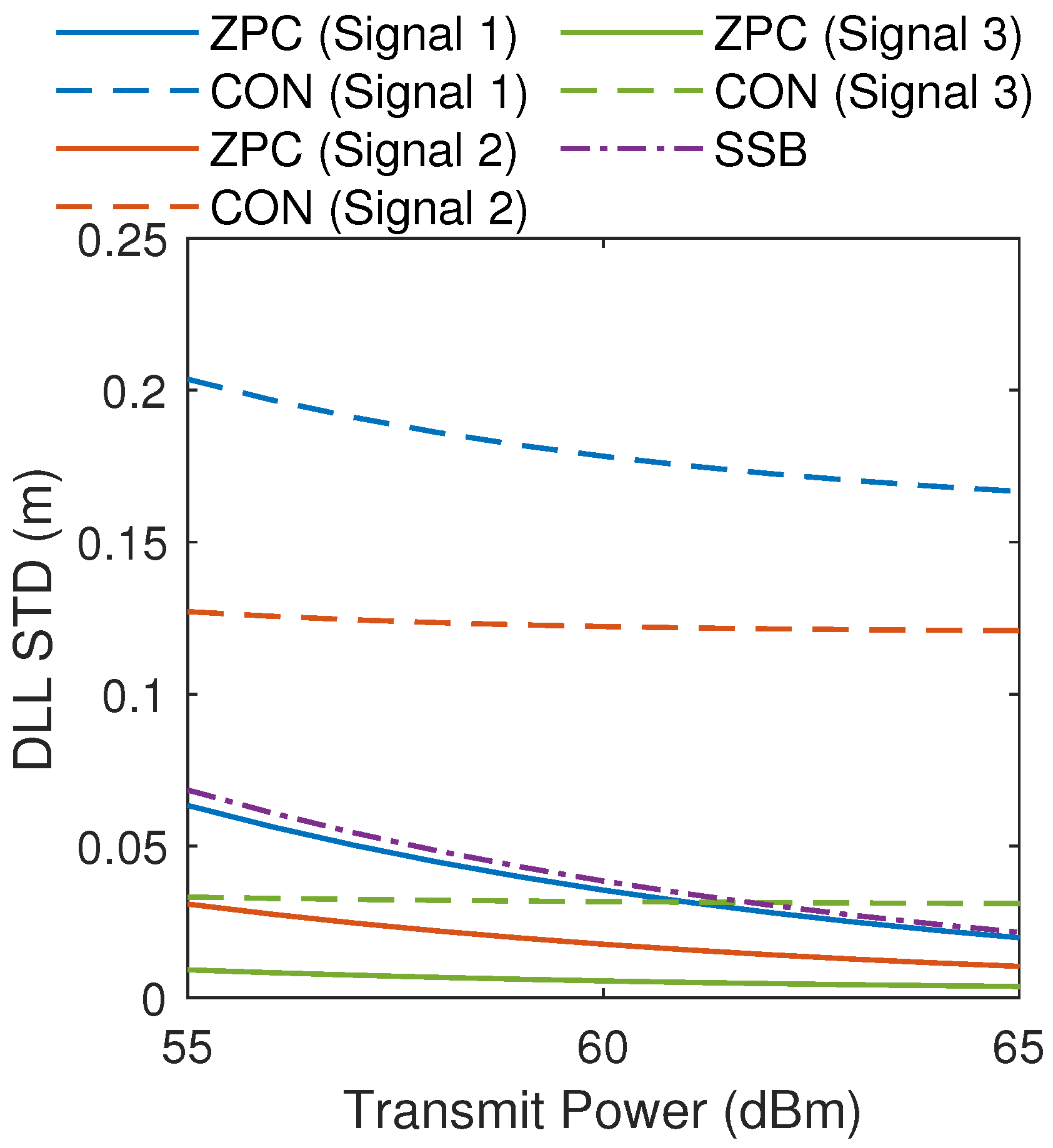
5.2. Tracking Performance Comparison of ZPC Against Other Works

This subsection compares our proposed ZPC receiver with other representative NR navigation receivers by tracking accuracy. The ZPC receiver is a cooperative navigation receiver that utilizes all detectable signal components as a local replica signal, including SSB, CSI-RS, and DMRS in PDSCH and PDCCH. Shamaei first proposed an NR receiver exclusively using SSB signals [37]. This reception strategy ignores other available navigation signals and does not consider the LEO navigation scenario. Neinavaie introduces a cognitive (CON) method for LEO OFDM-like signals to identify navigation reference signals without considering cyclic prefix influence [30,38].
For comprehensive comparison, three NR signal configurations are used in the experiment:
  • Signal 1: using default configuration as baseline (see Table 1).
  • Signal 2: equivalent bandwidth to Signal 1 with PDSCH spectral center shifted from zero frequency to 260 Δ f .
  • Signal 3: PDSCH bandwidth expands (1.8 MHz → 10.62 MHz), slot number increase (5 → 9), and DMRS-Additional-Position adjustment (0 → 1). For every NR frame, the resource elements of the reference signal increase from 830 to 6850, leading to an augmentation in the reference signal’s power.
Figure 7 compares the DLL tracking accuracy of different navigation reception strategies for three NR signals. The experimental results reveal four key findings. (1) The SSB navigation receiver (proposed by Shamaei) exhibits identical tracking performance for different NR signals. This receiver only utilizes SSB signals, so the PDSCH changes do not affect its tracking performance. (2) Our proposed ZPC receiver achieves superior tracking accuracy compared to SSB receivers. This enhancement stems from comprehensively utilizing all known reference signals, including SSB, DMRS in PDCCH and PDSCH, and CSI-RS. (3) Compared with CON, the ZPC receiver significantly enhances tracking accuracy for identical NR signals. Because the CON receiver does not consider the CP process, noise caused by CP exists. Moreover, the PBCH changes over time, and the CON receiver cannot recognize the PBCH signal. Notably, this paper assumes the CON receiver operates in an ideal scenario, whereas real-world implementations face additional challenges from dynamic PDSCH bandwidth allocation and an aperiodic reference signal. (4) The tracking accuracy of ZPC can significantly improve by using different NR configurations. because navigation signals demonstrate varying PSD and CNR across different NR configurations. So, the base stations can flexibly configure NR signals according to navigation requirements.

6. NR Tracking Performance Analysis for Different NR and Receiver Configuration

This section evaluates the impact of different NR signal and receiver configurations on tracking accuracy. The analysis results offer systematic insights for LEO OFDM tracking loop.

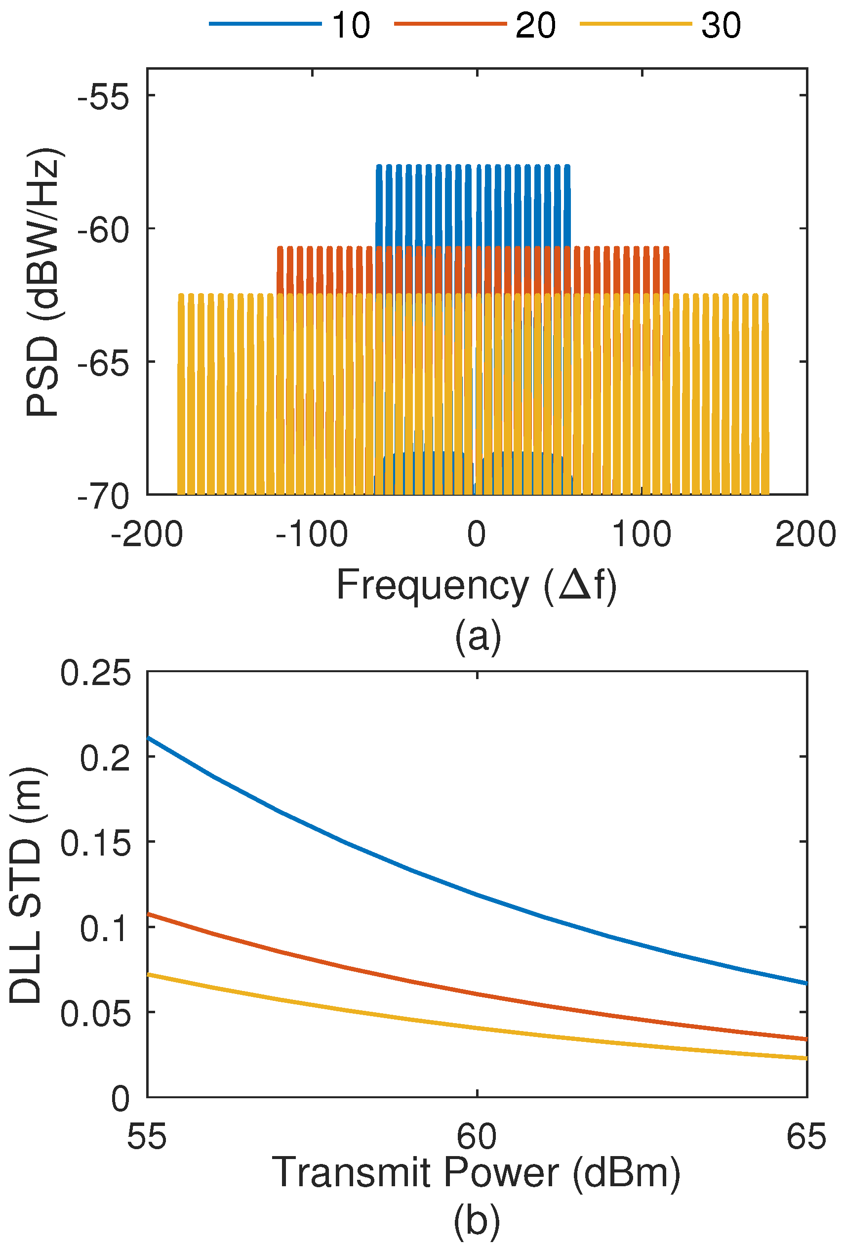
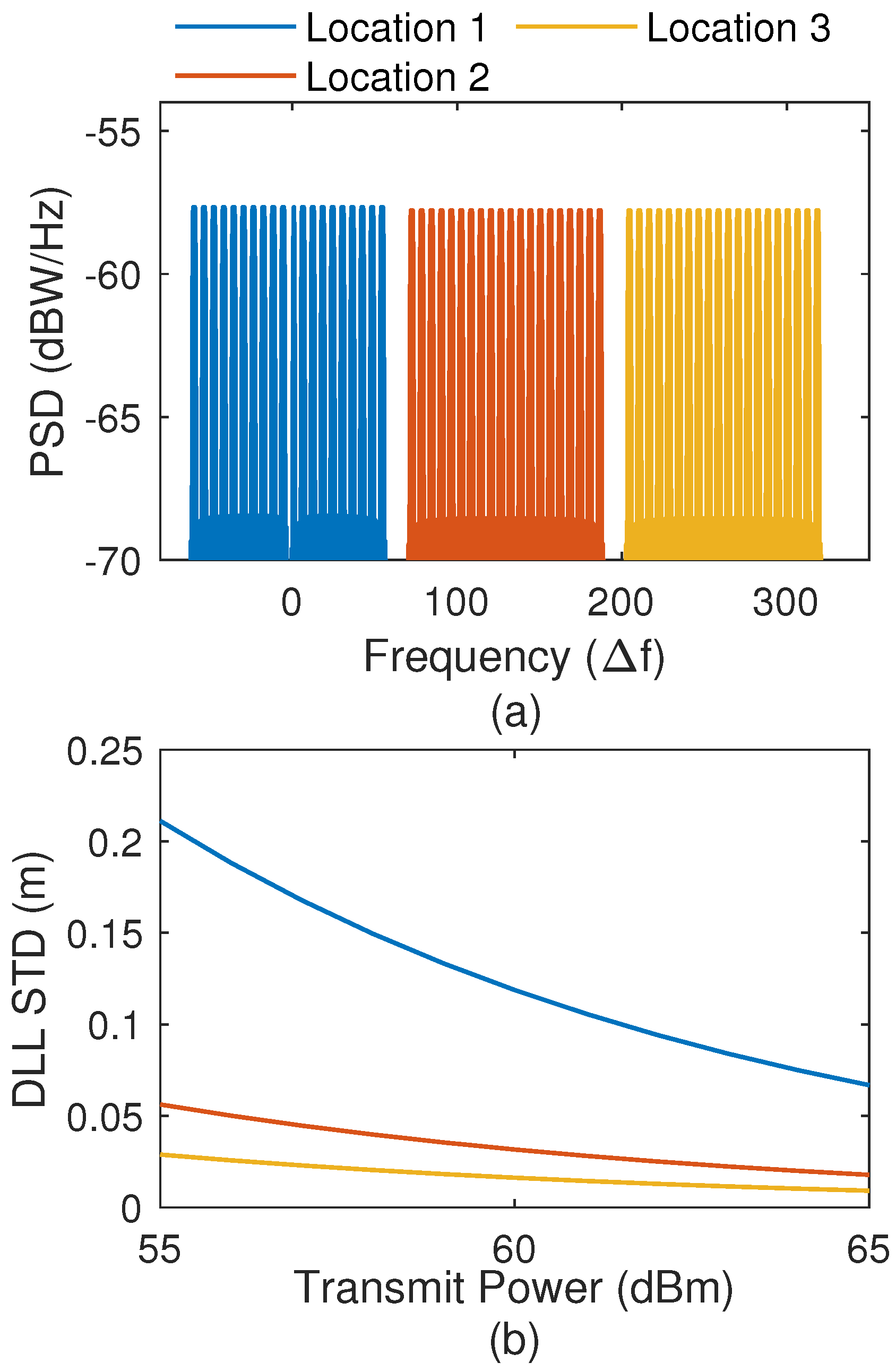
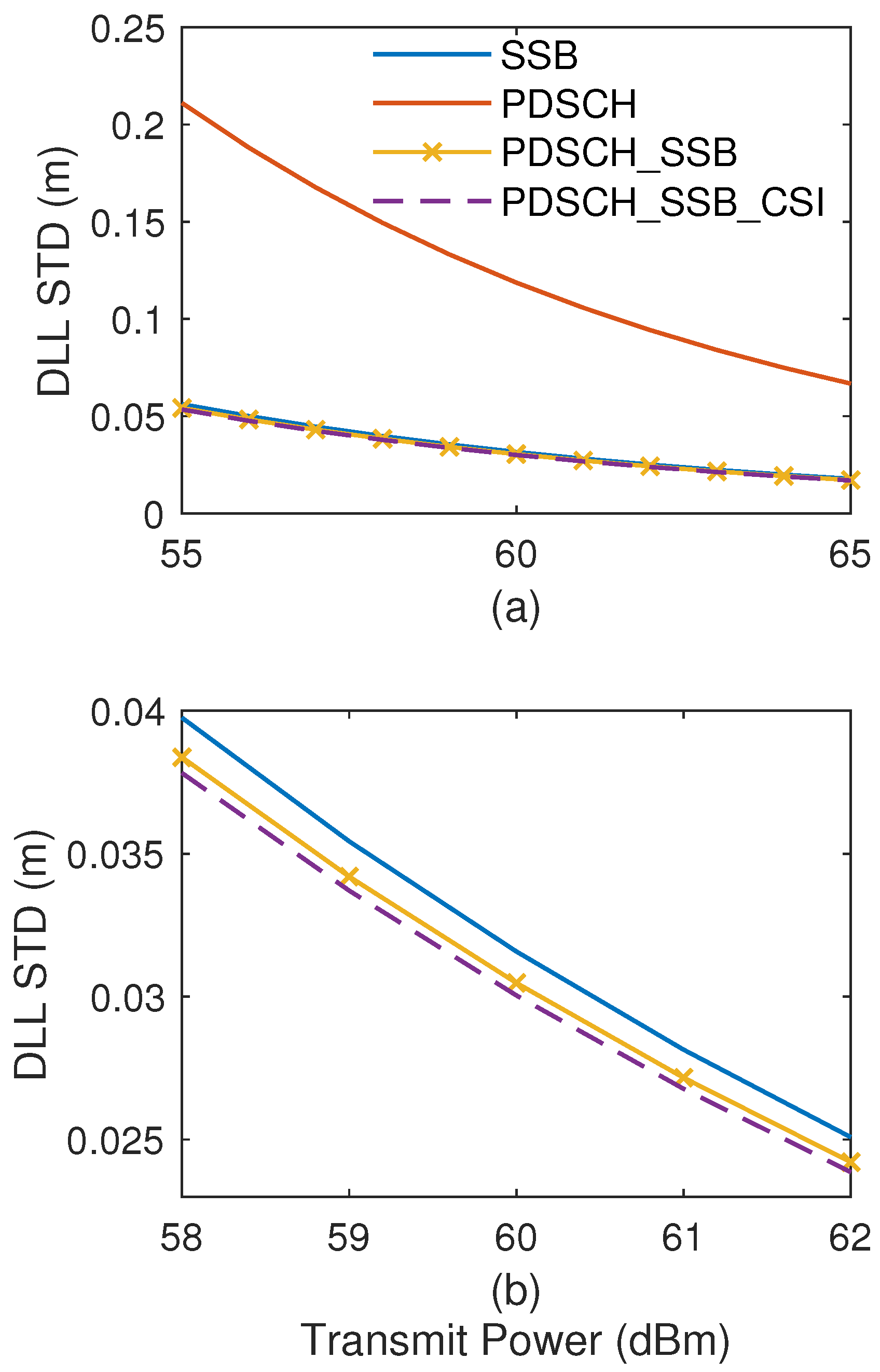
6.1. Impact of NR Signal Configuration on Tracking Accuracy

As described in Section 4, NELP is used as a code tracking loop and its theoretical tracking accuracy is as follows [76]:
σ NELP = B L , DLL 1 0.5 B L T coh β r / 2 β r / 2 G ( f ) sin 2 ( π f Δ ) d f C nav N 0 2 π β r / 2 β r / 2 f G ( f ) sin ( π f Δ ) d f 2 × 1 + β r / 2 β r / 2 G ( f ) cos 2 ( π f Δ ) d f T coh C nav N 0 β r / 2 β r / 2 G ( f ) cos ( π f Δ ) d f 2
where G ( f ) denotes the normalized PSD of the navigation signal, and β r represents the receiver front-end bandwidth. Δ = 2 d is the time interval between the early and late branches, and B L , DLL is the bandwidth of DLL. C nav / N 0 is the carrier-to-noise ratio, which can be determined by LEO transmit power (Appendix A) .
Unless otherwise specified, all NR signals follow default configurations listed in Table 1. This section only utilizes PDSCH DMRS as a local replica signal to evaluate the impact of NR configurations on tracking accuracy. The NR’s PDSCH contains 10 resource blocks (RBs), each comprising 12 subcarriers with a 15 kHz spacing. Hence, the default NR signal contains 120 subcarriers, and its bandwidth is 1.8 MHz. The center frequency of PDSCH is located at zero frequency.
The DLL tracking accuracy significantly depends on three key configurations: signal bandwidth, spectral distribution, and the proportion of NR reference signal. The base station flexibly configures these parameters according to the communication scenario. First, we discuss the relationship between tracking accuracy and signal bandwidth. The experiment chooses three signal bandwidths: 1.8 MHz, 3.6 MHz, and 5.4 MHz. Their corresponding reference signal PSD and DLL standard deviation (STD) are depicted in Figure 8. The comparison results reveal that expanded NR bandwidth significantly enhances the DLL tracking accuracy. At a fixed transmitting power of 60 dBm, the DLL tracking accuracy improves from 0.1187 m (1.8 MHz) to 0.0605 m (3.2 MHz) and 0.0506 m (5.4 MHz), respectively, by 49.03% and 65.80%. When the NR bandwidth increases, its spectral redistribution moves to higher frequencies. This spectral redistribution leads to higher tracking accuracy. Moreover, the tracking accuracy increases with transmitting power. Each five dBm power increment generates approximately 44% improvement in DLL tracking accuracy.
The spectral location of the NR signal constitutes another critical factor affecting tracking performance. For a fixed bandwidth NR signal, its center frequencies are placed at 0, 130 Δ f , and 260 Δ f , respectively. The receiver front-end bandwidth is 15.36 MHz to ensure complete signal reception. The relationship of NR signal spectral location and tracking accuracy is shown in Figure 9. We can find that the tracking accuracy increases with the center frequency of the NR signal. Under 60 dBm transmitting power, the tracking accuracy achieves 86.35% enhancement when the center frequency shifts from zero frequency to 260 Δ f . Moving the NR spectral to a higher frequency is conducive to improving tracking accuracy. Notably, the NR spectral should be within the receiver front bandwidth to ensure the integrity of the received NR signal.
The proportion of reference signals in NR signal is dynamically configured according to channel quality [31], significantly affecting DLL tracking accuracy. According to NR protocol, the parameter DMRS-Additional-Position adjusts PDSCH DMRS proportions. In the experiments, DMRS-Additional-Position is configured to 0, 1, and 2, achieving reference signal proportions of 4.17%, 8.33%, and 12.5%, respectively. Its tracking accuracy is plotted in Figure 10, and we can find that the DLL tracking accuracy increases with the proportion of the reference signal. At 60 dBm transmitting power, elevating the reference signal proportion from 4.17% to 8.33% and 12.5% yields 31.52% and 44.95% accuracy enhancements, respectively. Increasing the reference signal power allocation enhances the CNR of the navigation signal. Notably, increasing the reference proportions reduces the communication capacity, and reference signals occupy the same resource blocks as data transmission. This one-to-one compromise suggests that a 12.5% reference signal allocation would consume 12.5% of the total channel capacity, leaving 87.5% capacity for data. The optimal ratio should be determined by specific application requirements for navigation accuracy versus data throughput.
Overall, for fixed transmitting power, there are three NR configurations to enhance DLL tracking accuracy: first, maximizing signal bandwidth; second, the spectral of the NR signal is moved away from zero frequency as far as possible; and third, enhancing the proportion of the reference signal to increase navigation signal power.

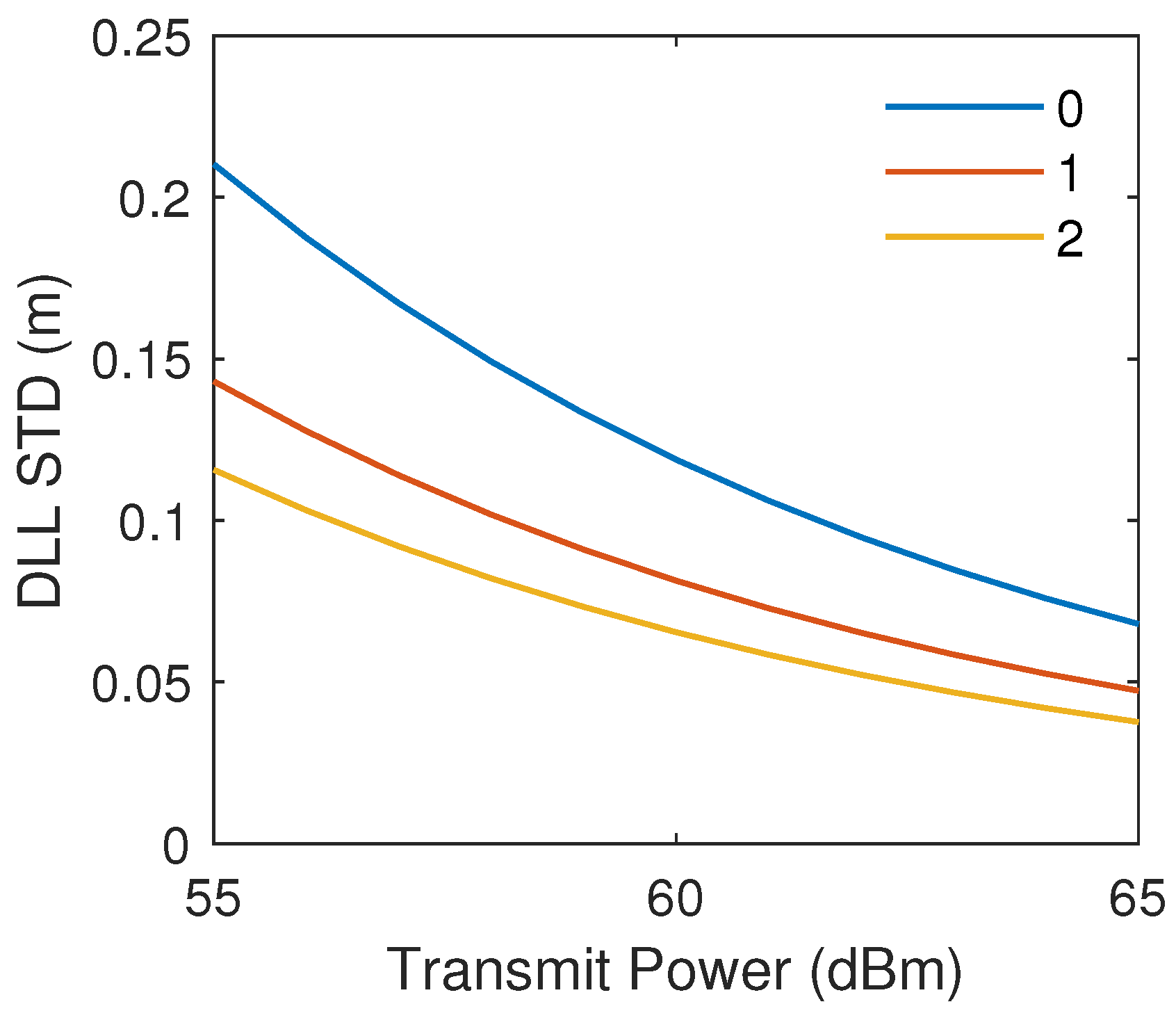
6.2. Impact of Receiver Configuration on Tracking Accuracy

DLL tracking accuracy is also determined by NR receiver configurations: (1) coherent integration time ( T coh ), (2) DLL loop bandwidth ( B L ), and (3) different local replica signals. T coh determines the integration duration of the integrate-and-dump filter, while the loop bandwidth B L governs both DLL tracking accuracy and dynamic response speed. Figure 11 and Table 2 demonstrate DLL tracking accuracy with different coherent integration time T coh and DLL bandwidth B L , and the results reveal that (1) at 60 dBm transmitting power with fixed B L = 20 Hz, decreasing T coh to 5 ms (relative to the baseline T coh = 10 ms, B L = 20 Hz) reduces DLL tracking accuracy by 2.52%, while elevating T coh to 15 ms enhances accuracy by 2.52%; and (2) at 60 dBm with fixed T coh = 10 ms, reducing B L from 20 Hz (baseline) to 5 Hz and 1 Hz yields DLL tracking accuracy improvements of 48.10% and 76.58% respectively, indicating the stronger influence of loop bandwidth on DLL tracking accuracy. Generally, extending T coh or reducing B L enhances DLL tracking accuracy.
Multiple reference signals, such as SSB, CSI-RS, and DMRS in PDCCH and PDSCH, can be used as local replica signals for an NR navigation receiver. The selection of local replica signals significantly influences DLL tracking accuracy. Previous experiments only utilize PDSCH DMRS as the local replica signal. This experiment systematically evaluates the impact of four NR replica signals: (1) SSB only; (2) PDSCH DMRS only; (3) combined PDSCH DMRS and SSB; and (4) combined PDSCH DMRS, SSB, and CSI-RS. The DLL tracking accuracy with different replica signals is plotted in Figure 12, and the proportion of the replica reference signal is listed in Table 3. The results show the following: First, exclusive use of PDSCH DMRS yields inferior tracking accuracy compared to other configurations; and second, composite replica signals demonstrate measurable improvements in tracking accuracy. At 60 dBm transmitting power, the combined PDSCH DMRS+SSB achieves a 3.48% accuracy enhancement over SSB only, while the full combination (PDSCH DMRS+SSB+CSI-RS) provides a 5.06% improvement. The proportion of CSI-RS and PDSCH DMRS is lower than 4%, so the improvement in tracking accuracy is not apparent. This enhancement in tracking accuracy is attributed to the increased correlator output power achieved through reference signal superposition. Hence, all predictable NR signals should be used as reference signals to improve navigation performance.
In summary, this section analyzes the impact of NR signal and receiver configurations on DLL tracking accuracy, offering systematic insights for LEO OFDM navigation design. Based on the tracking results, the positioning performance is discussed in the following.

7. Positioning Performance of LEO NR Signal

This section first simulates the motion trajectory of LEO satellites to generate the wireless channel characteristics. Next, the positioning performance of the ZPC receiver will be discussed, covering static and dynamic scenarios as well as the impacts of various error sources.

7.1. LEO Navigation Scenario

The propagation channel is a key part of the NR navigation system and is generated by LEO scenario simulation. We use Starlink’s orbit data to establish the LEO satellite motion scenario [77]. The static receiver is located in Xi’an Jiaotong University, Shaanxi, China (108.9788°E, 34.2481°N), at an altitude of 450 m. The dynamic receiver moves around the campus at a speed of 60 km/h. The simulation starts at 12:03 UTC on 5 November 2024, and lasts 15 s. As shown in Figure 13, the elevation angles of six visible LEO satellites are higher than 10 degrees, and their orbit parameters are shown in Table 4. Therefore, the satellite-receiver kinematic simulation generates their geometric distance and relative velocity. According to the distance and velocity, we obtain three key propagation channel characteristics: (1) path loss, (2) time delay, and (3) Doppler shift. These parameters are sampled at T coh interval to capture rapid channel variations. The received NR signal can be built based on the transmitting signal and propagation channel characteristics. The NR receiver includes multiple received signals from different LEO satellites, which experience various channels. We use DLL and FLL to measure the time delay and relative velocity of the received NR signals. Finally, at each T coh interval, the EKF updates these measured values to estimate the receiver state vector, such as position, velocity, and clock error.

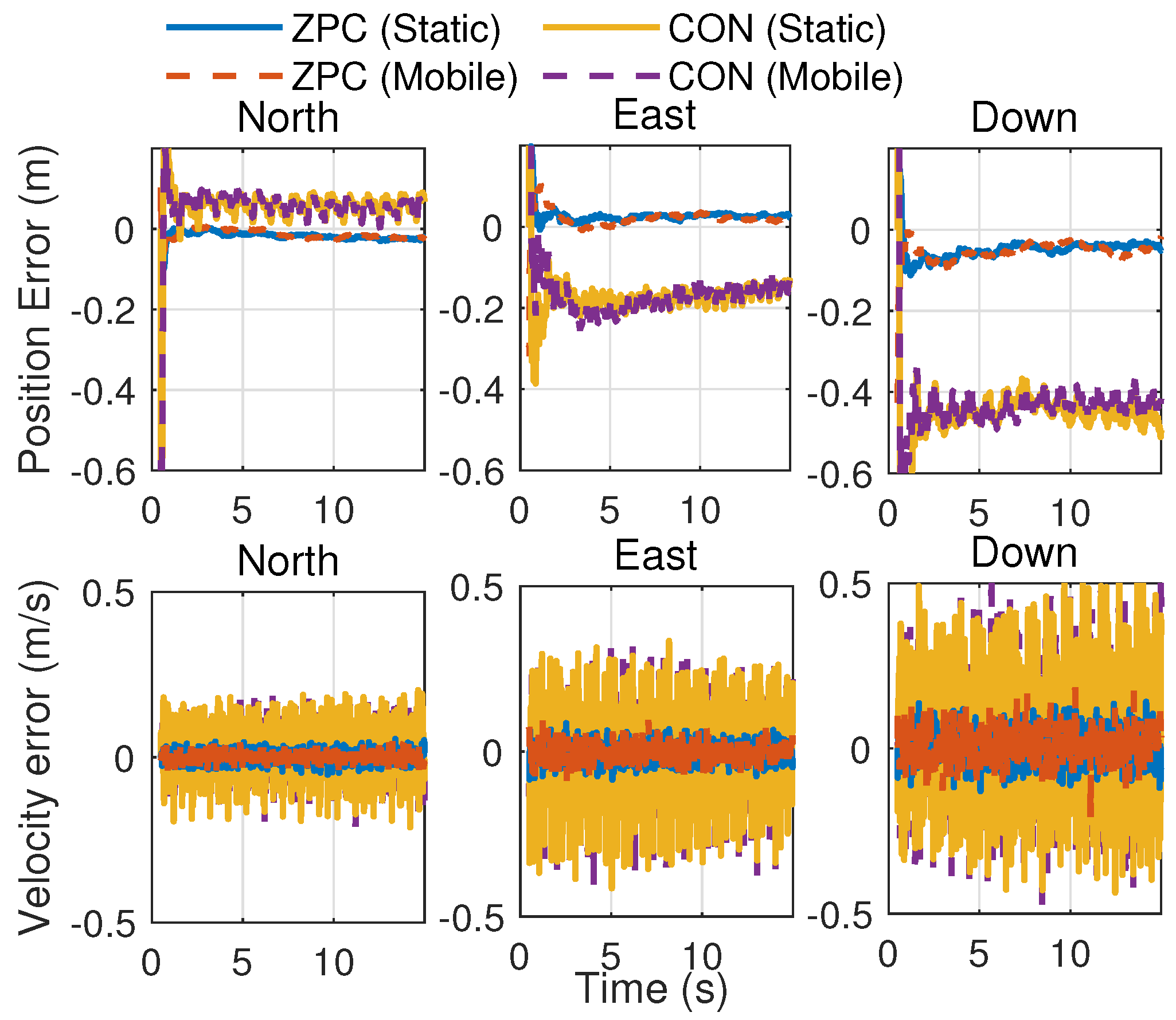
7.2. Positioning Performance

This section compares the three-dimensional (3D) positioning performance between the proposed ZPC navigation receiver and the CON receiver. As described in Section 4, the simulation of the LEO NR system consists of three core components: the NR transmitter, the LEO satellite channel, and the NR navigation receiver. The NR navigation receiver contains two sequential operational phases: signal acquisition and tracking. The acquisition module initially estimates the pseudo-random noise (PRN) sequence identifier, code phase delay, and carrier frequency offset. Like conventional GNSS receivers, the acquisition process detects peaks generated by correlating local replica and received signals. For brevity, the acquisition module is not expanded upon.
After successful acquisition, the receiver enters tracking mode. The DLL and FLL in the NR receiver estimate the pseudorange and pseudorange rate, respectively. Based on these measurements, the EKF output receiver’s state vector is in real time. The simulation experiment includes six viewed satellites, as described in Section 7.1, and their tracking errors are plotted in Figure 14. All the tracking error curves have a similar trend: There are transient responses at the beginning of the tracking (0–0.2 s), then the error curves tend to stabilize. The settling time is determined by the tracking loop bandwidth B L and is about 4.24 / B L [2].
The proposed ZPC and CON receiver’s tracking accuracy comparison is plotted in Figure 15. All simulation parameters for the ZPC and CON receivers are identical except for the replica signal and correlation process. This simulation configuration helps to compare the difference of receivers with high repeatability. The tracking accuracy is quantified through the standard deviation (STD) of ranging and velocity errors. The comparison results show that (1) significant differences exist in ranging and velocity error STD for different satellites, with this difference being caused by distinct orbital characteristics, leading to different Doppler shifts and carrier-to-noise ratios; and (2) the CON architecture ranging accuracy ranges from 17.8 to 27.9 cm, and velocity precision ranges from 3.66 to 4.93 cm/s. In contrast, the ZPC receiver demonstrates superior ranging accuracy (3.0~4.5 cm) and velocity accuracies (0.7~1.14 cm/s). ZPC achieves about an 80% improvement in both ranging and velocity accuracy. The CON receiver has two shortages: Omitting the CP process leads to inter-carrier interference (ICI), and it cannot identify PBCH signals decreasing the output power of correlation. The ZPC receiver addresses these shortages, and all known NR reference signals are utilized as local replica signals.
Next, we analyze the positioning performance of the LEO NR system, considering only the receiver noise while excluding other error sources. Four navigation reception strategies are utilized: static ZPC, mobile ZPC, static CON, and mobile CON. Figure 16 and Table 5 present the state estimation results from the EKF: the positioning and velocity error in the north–south, east–west, and altitude dimensions (the ECEF coordinate is generally used in the EKF filter; for clarity, ECEF outputs are converted to the ENU coordinate). The experiment results show the following. (1) The static ZPC receiver exhibits positioning error fluctuation during initial operation, stabilizing after 3 s of continuous operation. The means of positioning errors in the north, east, and horizontal directions measure 1.84 cm, 2.51 cm, and 4.54 cm, respectively. Moreover, the mean of the three-dimensional positioning accuracy is approximately 5.61 cm. (2) For static and mobile ZPC receivers, the difference of position and velocity errors is lower than 4%. Hence, they have similar position performances, and the ZPC receiver is robust in mobile scenarios. Moreover, the CON receiver demonstrates a similar position performance in both static and mobile scenarios. (3) The CON receiver demonstrates lower positioning accuracies: 5.85 cm, 17.33 cm, and 44.38 cm in the north, east, and horizontal directions. Compared to the CON receiver, our proposed ZPC receiver achieves 88.3% improvement in positioning accuracy. (4) The ZPC receiver also demonstrates a significantly enhanced velocity measurement compared to the CON receiver. The 3D velocity error mean of ZPC is 0.59 cm/s, while CON exhibits more significant errors of 2.42 cm/s. This corresponds to a 75.62% improvement in velocity accuracy.

7.3. Positioning Performance with Error Components

The previous simulation experiment only considered receiver thermal noise, but actual LEO NR systems necessitate comprehensive error modeling. These error sources include (1) the clock error of receiver and satellite; and (2) the propagation delay uncertainties induced by ionospheric and tropospheric effects. These errors are empirically configured as follows [78]:
  • Receiver clock phase offset: 0.1 m;
  • Receiver clock frequency drift: 0.01 m/s;
  • Satellite clock phase offset STD: 0.5 m;
  • Ionospheric error STD: 0.1 m;
  • Tropospheric error STD: 0.2 m.
Over the simulation duration, these error components are stable and can be viewed as constant. For the i-th satellite, its satellite clock offset δ t sat , i , ionospheric delay I i , and tropospheric delay T i can be modeled as an equivalent time-delay error δ t e q , i , e.g.,:
δ t e q , i = δ t sat , i + I i + T i
Moreover, the satellite-receiver geometry impacts the ionosphere and troposphere delay. In the simulation, the six satellites’ equivalent range delays c δ t e q , i are 0.238, 0.506, −0.747, 0.258, −0.466, and −0.062 m, respectively. Figure 17 and Table 6 demonstrate the effect of different error components on the positioning error. The experiment sets four error combinations: (1) white noise only; (2) white noise adds receiver clock offset; (3) composition of white noise, clock error, and ionospheric delay; and (4) composition of white noise, clock error, and ionospheric and tropospheric delays. The comparison results reveal that (1) the first and second configuration have identical positioning accuracies, indicating that the clock error has negligible positioning accuracy degradation due to receiver clock estimation in the state vector; and (2) the third and fourth configurations generate substantial error output, resulting in a notable EKF positioning bias. When comparing the results of the third and fourth configurations, it is evident that incorporating tropospheric effects exacerbates the positioning outcomes. Since the receiver is unable to estimate these errors, alternative error-elimination techniques should be adopted to eliminate them.
It is obvious that the simulation is essential for the LEO NR navigation system. The simulation can estimate positioning performance and analyze the influence of error components. The simulation method is cost-effective and repeatable in the LEO navigation system design.

8. Conclusions

This paper investigates the navigation potential of OFDM-based LEO broadband constellations and demonstrates that it can achieve a 5.61 cm 3D positioning accuracy. We assume the satellites transmit a 5G NR signal and introduce the structure of NR, focusing on reference signals applicable for navigation service such as SSB, DMRS, and CSI-RS, along with CP OFDM modulation. The PSD of NR reference signals is derived and used for the theoretical analysis of tracking performance.
Subsequently, the workflow of the LEO NR navigation system is outlined, encompassing the transmitter, channel, and navigation receiver. A ZPC is proposed for the tracking loop to eliminate CP and inter-carrier interference, ensuring that navigation performance remains unaffected by CP and communication data. Based on the tracking loop, an EKF positioning algorithm is developed.
We validate the interference-free property of ZPC and compare ZPC with conventional SSB and CON receivers in tracking performance. The experiment results demonstrate that the ZPC receiver has a significant improvement in tracking accuracy.
The comprehensive analysis evaluates navigation performance impacted by NR signal bandwidth, spectral allocation, reference signal proportion, and replica signal combinations. This parametric investigation provides theoretical support for tracking accuracy enhancement of the LEO NR system.
A LEO satellite motion scenario is simulated to characterize channel properties. Based on the EKF, the positioning performance of the LEO NR system and the impacts of error sources are systematically evaluated. The simulation results provide configuration recommendations for implementing opportunity navigation in LEO broadband constellations. This study proposes a low-cost, repeatable, and efficient methodology for analyzing LEO navigation performance through software simulation.
As LEO broadband constellations are primarily designed for communication services, future research should focus on developing integrated communication and navigation receivers.

Author Contributions

Conceptualization and original draft preparation, L.D. and X.Q.; theory and methodology, Y.Y. and H.L.; validation and data analysis, L.D. and J.M.; data curation and supervision, L.D. and T.W.; project administration, Y.Y. All authors have read and agreed to the published version of the manuscript.

Funding

This research was funded by “Key Laboratory of Intelligent Space TTC&O (Space Engineering University), Ministry of Education, NO. CYK2024-01-01”, and Grant “50903020401”.

Data Availability Statement

Data are contained within the article.

Conflicts of Interest

The authors declare no conflicts of interest.

Appendix A. Carrier-to-Noise Ratio of LEO NR Signal

This paper focuses on the navigation performance analysis of LEO NR signals. For navigation researchers, the carrier-to-noise ratio (CNR) is often used in navigation performance analysis. Next, we derive the relationship between LEO satellite transmitting power and CNR at the receiver. Assuming the transmitting power of the LEO satellite is P TX , the received power P RX after path loss (PL) attenuation is
P RX = P TX P L
where the unit of P TX and P RX is dBm.
Only the reference signal is used for navigation service in opportunity navigation scenarios. The reference signal includes system information broadcasting and channel estimation signals, occupying a subset of NR signals. Let α denote the proportion of the reference signal in the OFDM’s resource grid. Therefore, the navigation signal power C nav in the receiver becomes
C nav = 10 log 10 ( α ) + P RX
The resulting carrier-to-noise-density ratio is
C nav N 0 = P TX P L + 10 log 10 ( α ) N 0
where N 0 denotes the noise power spectral density ant its representative value is 203.98 dBW / Hz [2].
For a LEO satellite at 600 km altitude with reference signal ratio α = 19.44 % , Equation (A3) simplifies to
C nav N 0 P TX + 10.87
The transmitting power of LEO satellites ranges 40~57 dBm (10 W ~500 W ) [79,80]. Considering antenna gains (0~40 dBi ), the equivalent isotropic radiated power (EIRP) exhibits significant variation. For brevity, this paper assumes P TX = 55 ~ 65 dBm , yielding a navigation CNR of 65.87~75.87 dB · Hz .

References

  1. Langley, R.B.; Teunissen, P.J.G.; Montenbruck, O. Introduction to GNSS. In Springer Handbook of Global Navigation Satellite Systems; Springer International Publishing: Cham, Switzerland, 2017; pp. 3–23. [Google Scholar] [CrossRef]
  2. Xie, G. Principles of GPS and Receiver Design; Electronic Industry Press: Beijing, China, 2017. [Google Scholar]
  3. Schmidt, D.; Radke, K.; Camtepe, S.; Foo, E.; Ren, M. A Survey and Analysis of the GNSS Spoofing Threat and Countermeasures. ACM Comput. Surv. 2016, 48, 1–31. [Google Scholar] [CrossRef]
  4. Reid, T.G.; Neish, A.M.; Walter, T.; Enge, P.K. Broadband LEO Constellations for Navigation. NAVIGATION J. Inst. Navig. 2018, 65, 205–220. [Google Scholar] [CrossRef]
  5. Reid, T.G.; Neish, A.M.; Walter, T.F.; Enge, P.K. Leveraging commercial broadband leo constellations for navigating. In Proceedings of the 29th International Technical Meeting of the Satellite Division of the Institute of Navigation (Ion Gnss+ 2016), Portland, OR, USA, 12–16 September 2016; Volume 12, p. 2016. [Google Scholar]
  6. Chen, X.; Wei, Q.; Zhan, Y.; Kuang, L. Performance analysis of the packet-based PNT service in NGSO broadband satellite communication systems. China Commun. 2023, 20, 247–259. [Google Scholar] [CrossRef]
  7. Yang, Y.; Mao, Y.; Ren, X.; Jia, X.; Sun, B. Demand and key technology for a LEO constellation as augmentation of satellite navigation systems. Satell. Navig. 2024, 5, 11. [Google Scholar] [CrossRef]
  8. Iannucci, P.A.; Humphreys, T.E. Economical Fused LEO GNSS. In Proceedings of the 2020 IEEE/ION Position, Location and Navigation Symposium, PLANS 2020, Portland, OR, USA, 20–23 April 2020; pp. 426–443. [Google Scholar] [CrossRef]
  9. Reid, T.G.R.; Chan, B.; Goel, A.; Gunning, K.; Manning, B.; Martin, J.; Neish, A.; Perkins, A.; Tarantino, P. Satellite navigation for the age of autonomy. In Proceedings of the 2020 IEEE/ION Position, Location and Navigation Symposium (PLANS), Portland, OR, USA, 20–23 April 2020; pp. 342–352. [Google Scholar]
  10. Lei, W.; Deren, L.; Ruizhi, C.; Wenju, F.; Xin, S.; Hao, J. Low Earth Orbiter (LEO) Navigation Augmentation: Opportunities and Challenges. Chin. J. Eng. Sci. 2020, 22, 144. [Google Scholar] [CrossRef]
  11. Danchik, R.J. An overview of transit development. Johns Hopkins APL Tech. Dig. 1998, 19, 18–26. [Google Scholar]
  12. Wang, L.; Chen, R.; Li, D.; Zhang, G.; Shen, X.; Yu, B.; Wu, C.; Xie, S.; Zhang, P.; Li, M.; et al. Initial Assessment of the LEO Based Navigation Signal Augmentation System from Luojia-1A Satellite. Sensors 2018, 18, 3919. [Google Scholar] [CrossRef]
  13. Li, W.; Yang, Q.; Du, X.; Li, M.; Zhao, Q.; Yang, L.; Qin, Y.; Chang, C.; Wang, Y.; Qin, G. LEO augmented precise point positioning using real observations from two CENTISPACETM experimental satellites. GPS Solut. 2024, 28, 1–13. [Google Scholar] [CrossRef]
  14. Miller, N.S.; Koza, J.T.; Morgan, S.C.; Martin, S.M.; Neish, A.; Grayson, R.; Reid, T. SNAP: A Xona Space Systems and GPS Software-Defined Receiver. In Proceedings of the 2023 IEEE/ION Position, Location and Navigation Symposium (PLANS), Monterey, CA, USA, 24–27 April 2023; pp. 897–904. [Google Scholar] [CrossRef]
  15. Xiao, L.; Lei, Z. Analysis of iridium-augmented GPS positioning performance. J. Eng. 2019, 2019, 7139–7143. [Google Scholar] [CrossRef]
  16. Prol, F.S.; Bhuiyan, M.Z.H.; Kaasalainen, S.; Lohan, E.S.; Praks, J.; Celikbilek, K.; Kuusniemi, H. Simulations of Dedicated LEO-PNT Systems for Precise Point Positioning: Methodology, Parameter Analysis, and Accuracy Evaluation. IEEE Trans. Aerosp. Electron. Syst. 2024, 60, 6499–6516. [Google Scholar] [CrossRef]
  17. Stock, W.; Schwarz, R.T.; Hofmann, C.A.; Knopp, A. Survey On Opportunistic PNT With Signals From LEO Communication Satellites. IEEE Commun. Surv. Tutor. 2024, 27, 77–107. [Google Scholar] [CrossRef]
  18. Wang, L.; Lü, Z.; Tang, X.; Zhang, K.; Wang, F. LEO-augmented GNSS based on communication navigation integrated signal. Sensors 2019, 19, 4700. [Google Scholar] [CrossRef] [PubMed]
  19. Gutt, G.; Lawrence, D.; Cobb, S.; O’Connor, M. Recent PNT improvements and test results based on low earth orbit satellites. In Proceedings of the Annual Precise Time and Time Interval Systems and Applications Meeting, PTTI, Reston, VA, USA, 28 January–1 February 2018; pp. 72–79. [Google Scholar] [CrossRef]
  20. Wei, Q.; Chen, X.; Jiang, C.; Huang, Z. Time-of-Arrival Estimation for Integrated Satellite Navigation and Communication Signals. IEEE Trans. Wirel. Commun. 2023, 22, 9867–9880. [Google Scholar] [CrossRef]
  21. Xue, L.; Li, X.; Wu, W.; Dong, J. Multifunctional Signal Design for Measurement, Navigation and Communication Based on BOC and BPSK Modulation. Remote Sens. 2022, 14, 1653. [Google Scholar] [CrossRef]
  22. Huang, X.; Zhao, X.; Zhu, X.; Ou, G. MC-BOC: A New Interoperable Modulation and Performance Analysis for BeiDou B1 Signal; Springer: Singapore, 2018. [Google Scholar]
  23. Li, X.; Rao, Z.; Xue, L. A Channel Compensation Technique Based on Frequency-Hopping Binary Offset Carrier Modulated Signal. Remote Sens. 2023, 15, 1849. [Google Scholar] [CrossRef]
  24. Li, X.; Zeng, X.; Xue, L. Integrated Communication and Measurement System with BOC-Assisted OFDM. Drones 2022, 7, 14. [Google Scholar] [CrossRef]
  25. Reid, T.G.R.; Walter, T.; Enge, P.K.; Lawrence, D.; Cobb, H.S.; Gutt, G.; O’Connor, M.; Whelan, D. Navigation from Low Earth Orbit: Part 1: Concept, Current Capability, and Future Promise. In Position, Navigation, and Timing Technologies in the 21st Century; John Wiley & Sons, Ltd.: Hoboken, NJ, USA, 2020; Chapter 43; pp. 1359–1379. [Google Scholar] [CrossRef]
  26. Kassas, Z.Z.M. Navigation from Low-Earth Orbit: Part 2: Models, Implementation, and Performance. In Position, Navigation, and Timing Technologies in the 21st Century; John Wiley & Sons, Ltd.: Hoboken, NJ, USA, 2020; Chapter 43; pp. 1381–1412. [Google Scholar] [CrossRef]
  27. Singh, U.K.; Shankar, M.R.B.; Ottersten, B. Opportunistic localization using LEO signals. In Proceedings of the 2022 56th Asilomar Conference on Signals, Systems, and Computers, Pacific Grove, CA, USA, 31 October–2 November 2022; pp. 894–899. [Google Scholar]
  28. Cho, Y.S. MIMO-OFDM Wireless Communications with MATLAB; Wiley Publishing: Hoboken, NJ, USA, 2010. [Google Scholar]
  29. Humphreys, T.E.; Iannucci, P.A.; Komodromos, Z.M.; Graff, A.M. Signal Structure of the Starlink Ku-Band Downlink. IEEE Trans. Aerosp. Electron. Syst. 2023, 59, 6016–6030. [Google Scholar] [CrossRef]
  30. Neinavaie, M.; Kassas, Z.M. Unveiling Starlink LEO Satellite OFDM-Like Signal Structure Enabling Precise Positioning. IEEE Trans. Aerosp. Electron. Syst. 2024, 60, 2486–2489. [Google Scholar] [CrossRef]
  31. ETSI. 5G NR Physical Channels and Modulation (3GPP TS 38.211 Version 15.2.0 Release 15). 2018. Available online: https://shop.standards.ie/en-ie/standards/etsi-ts-138-211-v15-2-0-2018-07--1399445_saig_etsi_etsi_3585366/ (accessed on 18 June 2025).
  32. Tataria, H.; Shafi, M.; Molisch, A.F.; Dohler, M.; Sjoland, H.; Tufvesson, F. 6G Wireless Systems: Vision, Requirements, Challenges, Insights, and Opportunities. Proc. IEEE 2021, 109, 1166–1199. [Google Scholar] [CrossRef]
  33. Dogra, A.; Jha, R.K.; Jain, S. A Survey on beyond 5G Network with the Advent of 6G: Architecture and Emerging Technologies. IEEE Access 2021, 9, 67512–67547. [Google Scholar] [CrossRef]
  34. Shahid, H.; Amatetti, C.; Campana, R.; Tong, S.; Panaitopol, D.; Vanelli-Coralli, A.; Mohamed, A.; Zhang, C.; Khalifa, E.; Medeiros, E.; et al. Emerging Advancements in 6G NTN Radio Access Technologies: An Overview. In Proceedings of the 2024 Joint European Conference on Networks and Communications and 6G Summit, EuCNC/6G Summit 2024, Antwerp, Belgium, 3–6 June 2024; pp. 593–598. [Google Scholar] [CrossRef]
  35. Hu, B.; Li, X.; Xue, L. A Pilot-Based Integration Method of Ranging and LS Channel Estimation for OFDM Systems. Drones 2022, 6, 400. [Google Scholar] [CrossRef]
  36. Abdallah, A.; Khalife, J.; Kassas, Z.M. Exploiting On-Demand 5G Downlink Signals for Opportunistic Navigation. IEEE Signal Process. Lett. 2023, 30, 389–393. [Google Scholar] [CrossRef]
  37. Shamaei, K.; Kassas, Z.M. Receiver Design and Time of Arrival Estimation for Opportunistic Localization with 5G Signals. IEEE Trans. Wirel. Commun. 2021, 20, 4716–4731. [Google Scholar] [CrossRef]
  38. Neinavaie, M.; Kassas, Z.M. Cognitive Sensing and Navigation With Unknown OFDM Signals With Application to Terrestrial 5G and Starlink LEO Satellites. IEEE J. Sel. Areas Commun. 2024, 42, 146–160. [Google Scholar] [CrossRef]
  39. Kassas, Z.M.; Kozhaya, S.; Kanj, H.; Saroufim, J.; Hayek, S.W.; Neinavaie, M.; Khairallah, N.; Khalife, J. Navigation with Multi-Constellation LEO Satellite Signals of Opportunity: Starlink, OneWeb, Orbcomm, and Iridium. In Proceedings of the 2023 IEEE/ION Position, Location and Navigation Symposium, PLANS 2023, Monterey, CA, USA, 24–27 April 2023; pp. 338–343. [Google Scholar] [CrossRef]
  40. Neinavaie, M.; Khalife, J.; Kassas, Z.M. Acquisition, Doppler Tracking, and Positioning with Starlink LEO Satellites: First Results. IEEE Trans. Aerosp. Electron. Syst. 2022, 58, 2606–2610. [Google Scholar] [CrossRef]
  41. Khalife, J.; Neinavaie, M.; Kassas, Z.Z. The First Carrier Phase Tracking and Positioning Results With Starlink LEO Satellite Signals. IEEE Trans. Aerosp. Electron. Syst. 2022, 58, 1487–1491. [Google Scholar] [CrossRef]
  42. Saroufim, J.; Hayek, S.W.; Kassas, Z.M. Simultaneous LEO satellite tracking and differential LEO-aided IMU navigation. In Proceedings of the 2023 IEEE/ION Position, Location and Navigation Symposium (PLANS), Monterey, CA, USA, 24–27 April 2023; pp. 179–188. [Google Scholar]
  43. McLemore, B.; Psiaki, M.L. Navigation using Doppler shift from LEO constellations and INS data. IEEE Trans. Aerosp. Electron. Syst. 2022, 58, 4295–4314. [Google Scholar] [CrossRef]
  44. Yang, C.; Zang, B.; Gu, B.; Zhang, L.; Dai, C.; Long, L.; Zhang, Z.; Ding, L.; Ji, H. Doppler positioning of dynamic targets with unknown LEO satellite signals. Electronics 2023, 12, 2392. [Google Scholar] [CrossRef]
  45. Kassas, Z.M. Navigation with cellular signals of opportunity. In Position, Navigation, and Timing Technologies in the 21st Century; Wiley: Hoboken, NJ, USA, 2020. [Google Scholar]
  46. Kassas, Z.M.; Khairallah, N.; Kozhaya, S. Ad Astra: Simultaneous Tracking and Navigation With Megaconstellation LEO Satellites. IEEE Aerosp. Electron. Syst. Mag. 2024, 39, 46–71. [Google Scholar] [CrossRef]
  47. Neinavaie, M.; Khalife, J.; Kassas, Z.M. Cognitive Opportunistic Navigation in Private Networks with 5G Signals and beyond. IEEE J. Sel. Top. Signal Process. 2022, 16, 129–143. [Google Scholar] [CrossRef]
  48. Jardak, N.; Jault, Q. The potential of LEO satellite-based opportunistic navigation for high dynamic applications. Sensors 2022, 22, 2541. [Google Scholar] [CrossRef] [PubMed]
  49. Khairallah, N.; Kassas, Z.M. Ephemeris Tracking and Error Propagation Analysis of LEO Satellites With Application to Opportunistic Navigation. IEEE Trans. Aerosp. Electron. Syst. 2024, 60, 1242–1259. [Google Scholar] [CrossRef]
  50. Wang, J.; Zhang, Y.; Zhao, S.; He, J.; Shen, Y.; Jiang, X. A Survey on Authentication in Satellite Internet. J. Netw. Netw. Appl. 2022, 2, 183–194. [Google Scholar] [CrossRef]
  51. Iannucci, P.A.; Humphreys, T.E. Fused Low-Earth-Orbit GNSS. IEEE Trans. Aerosp. Electron. Syst. 2024, 60, 3730–3749. [Google Scholar] [CrossRef]
  52. Shamaei, K.; Kassas, Z.M. A Joint TOA and DOA Acquisition and Tracking Approach for Positioning with LTE Signals. IEEE Trans. Signal Process. 2021, 69, 2689–2705. [Google Scholar] [CrossRef]
  53. Yang, C.; Arizabaleta-Diez, M.; Weitkemper, P.; Pany, T. An Experimental Analysis of Cyclic and Reference Signals of 4G LTE for TOA Estimation and Positioning in Mobile Fading Environments. IEEE Aerosp. Electron. Syst. Mag. 2022, 37, 16–41. [Google Scholar] [CrossRef]
  54. Yang, C.; Pany, T.; Weitkemper, P. Effect of Antenna Ports on TOA Estimation with 4G LTE Signals in Urban Mobile Environments. In Proceedings of the 33rd International Technical Meeting of the Satellite Division of the Institute of Navigation, ION GNSS+ 2020, Online, 22–25 September 2020; pp. 2166–2181. [Google Scholar] [CrossRef]
  55. Wang, P.; Morton, Y.J. Impact Analysis of Intercell Interference in Cellular Networks for Navigation Applications. IEEE Trans. Aerosp. Electron. Syst. 2023, 59, 685–694. [Google Scholar] [CrossRef]
  56. Liu, Z.; Chen, L.; Zhou, X.; Shen, N.; Chen, R. Multipath tracking with LTE signals for accurate TOA estimation in the application of indoor positioning. Geo-Spat. Inf. Sci. 2023, 26, 31–43. [Google Scholar] [CrossRef]
  57. Wang, P.; Morton, Y.J. Multipath Estimating Delay Lock Loop for LTE Signal TOA Estimation in Indoor and Urban Environments. IEEE Trans. Wirel. Commun. 2020, 19, 5518–5530. [Google Scholar] [CrossRef]
  58. Abdallah, A.; Kassas, Z. Multipath Mitigation via Synthetic Aperture Beamforming for Indoor and Deep Urban Navigation. IEEE Trans. Veh. Technol. 2021, 70, 8838–8853. [Google Scholar] [CrossRef]
  59. Whiton, R.; Chen, J.; Johansson, T.; Tufvesson, F. Urban Navigation with LTE using a Large Antenna Array and Machine Learning. In Proceedings of the IEEE Vehicular Technology Conference, Helsinki, Finland, 19–22 June 2022; pp. 1–5. [Google Scholar] [CrossRef]
  60. Khalife, J.; Kassas, Z.M. Differential Framework for Submeter-Accurate Vehicular Navigation With Cellular Signals. IEEE Trans. Intell. Veh. 2023, 8, 732–744. [Google Scholar] [CrossRef]
  61. Abdallah, A.A.; Kassas, Z.M. UAV navigation with 5G carrier phase measurements. In Proceedings of the 34th International Technical Meeting of the Satellite Division of the Institute of Navigation, ION GNSS+ 2021, Online, 20–24 September 2021; pp. 3294–3306. [Google Scholar] [CrossRef]
  62. Xhafa, A.; Del Peral-Rosado, J.A.; López-Salcedo, J.A.; Seco-Granados, G. Evaluation of 5g positioning performance based on utdoa, aoa and base-station selective exclusion. Sensors 2022, 22, 101. [Google Scholar] [CrossRef]
  63. Koivisto, M.; Talvitie, J.; Rastorgueva-Foi, E.; Lu, Y.; Valkama, M. Channel Parameter Estimation and TX Positioning With Multi-Beam Fusion in 5G mmWave Networks. IEEE Trans. Wirel. Commun. 2022, 21, 3192–3207. [Google Scholar] [CrossRef]
  64. Lapin, I.; Seco-Granados, G.; Renaudin, O.; Zanier, F.; Ries, L. Joint Delay and Phase Discriminator Based on ESPRIT for 5G NR Positioning. IEEE Access 2021, 9, 126550–126563. [Google Scholar] [CrossRef]
  65. Wen, F.; Kulmer, J.; Witrisal, K.; Wymeersch, H. 5G Positioning and Mapping with Diffuse Multipath. IEEE Trans. Wirel. Commun. 2021, 20, 1164–1174. [Google Scholar] [CrossRef]
  66. Gante, J.; Sousa, L.; Falcao, G. Dethroning GPS: Low-Power Accurate 5G Positioning Systems Using Machine Learning. IEEE J. Emerg. Sel. Top. Circuits Syst. 2020, 10, 240–252. [Google Scholar] [CrossRef]
  67. Liu, Z.; Chen, L.; Zhou, X.; Jiao, Z.; Guo, G.; Chen, R. Machine Learning for Time-of-Arrival Estimation With 5G Signals in Indoor Positioning. IEEE Internet Things J. 2023, 10, 9782–9795. [Google Scholar] [CrossRef]
  68. Liu, Z.; Chen, L.; Jiao, Z.; Lu, X.; Ruan, Y.; Chen, R. MLLoc: Machine Learning Location System Based on RAIM in Mobile Networks. IEEE Sens. J. 2024, 24, 16953–16960. [Google Scholar] [CrossRef]
  69. Khalife, J.; Neinavaie, M.; Kassas, Z.M. Navigation with differential carrier phase measurements from megaconstellation LEO satellites. In Proceedings of the 2020 IEEE/ION Position, Location and Navigation Symposium (PLANS), Portland, OR, USA, 20–23 April 2020; pp. 1393–1404. [Google Scholar]
  70. Kozhaya, S.; Kassas, Z.M. On the Fundamental Tracking Performance and Design Considerations of Radio Navigation. IEEE J. Sel. Areas Commun. 2024, 42, 2395–2409. [Google Scholar] [CrossRef]
  71. Zhao, C.; Qin, H.; Li, Z. Doppler Measurements from Multiconstellations in Opportunistic Navigation. IEEE Trans. Instrum. Meas. 2022, 71, 1–9. [Google Scholar] [CrossRef]
  72. Cassel, R.S.; Scherer, D.R.; Wilburne, D.R.; Hirschauer, J.E.; Burke, J.H. Impact of improved oscillator stability on LEO-based satellite navigation. In Proceedings of the 2022 International Technical Meeting of the Institute of Navigation, Long Beach, CA, USA, 25–27 January 2022; pp. 893–905. [Google Scholar]
  73. Zhao, C.; Qin, H.; Wu, N.; Wang, D. Analysis of Baseline Impact on Differential Doppler Positioning and Performance Improvement Method for LEO Opportunistic Navigation. IEEE Trans. Instrum. Meas. 2023, 72, 1–10. [Google Scholar] [CrossRef]
  74. Yao, Z.; Lu, M. Next-Generation GNSS Signal Design: Theories, Principles and Technologies; Springer: Berlin/Heidelberg, Germany, 2021. [Google Scholar]
  75. Xie, G. Principles of GNSS: GPS, GLONASS, and Galileo; Publishing House of Electronics Industry: Beijing, China, 2019; p. 443. [Google Scholar]
  76. Betz, J.W.; Kolodziejski, K.R. Generalized theory of code tracking with an early-late discriminator part II: Noncoherent Processing and Numerical Results. IEEE Trans. Aerosp. Electron. Syst. 2009, 45, 1538. [Google Scholar] [CrossRef]
  77. Celestrak. Starlink TLE Data. Available online: https://celestrak.org/NORAD/elements/gp.php?GROUP=starlink (accessed on 5 November 2024).
  78. Groves, P. Principles of GNSS, Inertial, and Multisensor Integrated Navigation Systems, 2nd ed.; Artech: London, UK, 2013. [Google Scholar]
  79. Ippolito, L.J., Jr. Satellite Communications Systems Engineering: Atmospheric Effects, Satellite Link Design and System Performance; John Wiley & Sons: Hoboken, NJ, USA, 2017. [Google Scholar]
  80. 3rd Generation Partnership Project; Technical Specification Group Radio Access Network; Study on Narrow-Band Internet of Things (NB-IoT)/enhanced Machine Type Communication (eMTC) support for Non-Terrestrial Networks (NTN) (Release 17). 3GPP Technical Report TR 36.763 V0.2.0, 3rd Generation Partnership Project (3GPP). 2021. Available online: https://portal.3gpp.org/desktopmodules/Specifications/SpecificationDetails.aspx?specificationId=3747 (accessed on 5 November 2024).
Figure 1. New radio (NR) physical channel structure and resource grid.
Remotesensing 17 02116 g001
Figure 2. Power spectral density (PSD) of NR. The unit of horizontal axis is Δ f .
Remotesensing 17 02116 g002
Figure 3. NR navigation system block diagram.
Remotesensing 17 02116 g003
Figure 4. Different correlation method: (a) conventional CP-based method with integration interval T sym (replica signal includes CP); (b) effective integration interval of proposed ZPC method is T u (replica signal utilizes zero-padding).
Remotesensing 17 02116 g004
Figure 5. EKF update process.
Remotesensing 17 02116 g005
Figure 6. The relationship between delay-locked loop (DLL) tracking accuracy and different correlation methods. DLL standard deviation (STD) represents the DLL tracking accuracy.
Remotesensing 17 02116 g006
Figure 7. DLL tracking accuracy for different NR signals and reception strategies. For signals 1, 2, and 3, ZPC, respectively, achieves 80.3%, 85.6%, and 82.6% higher tracking accuracy than CON.
Remotesensing 17 02116 g007
Figure 8. Relationship between NR signal bandwidth and tracking accuracy. (a) PSD of NR reference signal; (b) DLL STD with different bandwidth NR signal. At 60 dBm transmitting power, the DLL has 65.8% accuracy gain at 5.4 MHz compared to 1.8 MHz.
Remotesensing 17 02116 g008
Figure 9. Relationship between signal frequency location and tracking accuracy. (a) PSD of NR reference signal; (b) DLL STD with different NR frequency location.
Remotesensing 17 02116 g009
Figure 10. Relationship between portion of NR reference signal and tracking accuracy.
Remotesensing 17 02116 g010
Figure 11. DLL tracking accuracy with different coherent integration time T coh and DLL loop bandwidth B L .
Remotesensing 17 02116 g011
Figure 12. DLL tracking accuracy with different local replica signals. (a) Transmitting power range: 55~65 dBm. (b) Zoomed-in range: 58~62 dBm.
Remotesensing 17 02116 g012
Figure 13. The trajectory of LEO satellites and receiver.
Remotesensing 17 02116 g013
Figure 14. ZPC receiver tracking errors over time: (a) ranging error; (b) velocity error.
Remotesensing 17 02116 g014
Figure 15. Stable tracking accuracy for different LEO satellites in static scenario: (a) ranging accuracy; (b) velocity accuracy.
Remotesensing 17 02116 g015
Figure 16. Position and velocity error comparison: ZPC and CON receiver.
Remotesensing 17 02116 g016
Figure 17. Position and velocity error with different error components.
Remotesensing 17 02116 g017
Table 1. Default configurations in LEO NR navigation.
ParameterValue
NR BasicFFT Length1024
Subcarrier Spacing (kHz)15
Sampling Rate (MHz)15.36
Period (ms)10
Slot Number Per Period5
Symbol Length Per Slot8
Used BandWidth (MHz)1.8
Resource Block Number10
Subcarrier Number240
PDSCHModulationQPSK
DMRS MappingType A
DMRS-TypeA-Position2
DMRSLength1
DMRS-Additional-Position0
DMRS-Configuration-Type2
DMRS proportion α 3.50%
Delay-locked loop
(DLL)
B L (Hz)20
Damping Coefficient0.707
Integration Time (ms)10
Early–Late Spacing Δ (Sampling Time)2
Transmit Power (W)10
Proportion of Reference Signal in NR signal19.44%
Receiver Front-end Bandwidth (MHz)15.36
Sampling Rate (MHz)15.36
Table 2. DLL tracking accuracy summary for different coherent integration time T coh and DLL loop bandwidth B L at 60 dBm transmit power.
T coh (ms) B L (Hz)DLL STD (m)DLL STD Improvement
5200.122−2.52%
10200.1190% (baseline)
15200.1162.52%
1050.06247.9%
1010.02876.5%
Table 3. Resource elements distribution in an NR frame.
PBCHCSIPDSCH DMRSPDSCH DataSum
Resource Elements8308020046005710
Resource Proportion
(Power Proportion)
14.54%1.40%3.50%80.56%100.00%
Table 4. Orbital data from Starlink satellites [77].
ParameterSat 1Sat 2Sat 3Sat 4Sat 5Sat 6
Semi-major Axis a (km)713669806970705068207130
Eccentricity e0.00015680.00014590.00016030.00014320.00014640.0001406
Inclination i (°)53.053153.214653.215743.003943.001953.1584
RAAN Ω (°)189.0089191.0164305.9367291.2627294.6071192.7046
Argument of Perigee ω (°)63.149578.672589.8188270.5086262.038861.5981
Mean Anomaly M (°)82.5489166.1697347.1216212.3624208.9401164.3645
Altitude 1 (km)765609599679449759
1 The radius of Earth is 6371 km.
Table 5. Position and velocity error statistics: ZPC and CON receiver.
MeanStd
NorthEastDown3DNorthEastDown3D
Position error
(m)
ZPC (Static)−0.01840.0251−0.04540.05610.00550.00500.00960.0059
ZPC (Mobile)−0.01520.0184−0.05070.05850.00870.00970.01390.0091
CON (Static)0.0585−0.1733−0.44380.48070.01840.01720.02490.0242
CON (Mobile)0.0570−0.1765−0.43270.47170.01990.02700.02310.0288
Velocity error
(m/s)
ZPC (Static)0.0005−0.00390.00690.04870.01690.02670.04590.0281
ZPC (Mobile)−0.0012−0.00090.01150.04840.01600.02650.04650.0301
CON (Static)0.0189−0.01260.03510.21570.07600.13610.18760.1212
CON (Mobile)0.0171−0.00990.04140.22000.0762−0.13830.19180.1240
Table 6. Position and velocity error statistics for different error components.
MeanStd
NorthEastDown3DNorthEastDown3D
Position error
(m)
Noise−0.01840.0252−0.04540.05610.00550.00500.00960.0059
Noise and clock−0.01840.0252−0.04540.05610.00550.00500.00960.0059
Noise, clock,
and ION 1
−1.2169−0.10981.82102.19510.01350.09280.05370.0445
Noise, clock,
ION, and TRO 2
−1.73071.72015.16435.71430.05400.11420.19380.1591
Velocity error
(m/s)
Noise0.0005−0.00390.00690.04870.01690.02670.04590.0281
Noise and clock0.0005−0.00390.00690.04870.01690.02670.04590.0281
Noise, clock,
and ION
−0.0184−0.00550.05020.06960.01700.02680.04600.0341
Noise, clock,
ION, and TRO
−0.0199−0.02790.08570.10240.01720.02740.04610.0347
1 ION denotes inonospheric; 2 TRO denotes tropospheric.
Disclaimer/Publisher’s Note: The statements, opinions and data contained in all publications are solely those of the individual author(s) and contributor(s) and not of MDPI and/or the editor(s). MDPI and/or the editor(s) disclaim responsibility for any injury to people or property resulting from any ideas, methods, instructions or products referred to in the content.

