Article

Research on Spaceborne Neural Network Accelerator and Its Fault Tolerance Design

1
State Key Laboratory of Integrated Services Networks, Xidian University, Xi’an 710071, China
2
China Academy of Space Technology (Xi’an), Xi’an 710100, China
3
School of Computer Science and Technology, Xidian University, Xi’an 710071, China
*
Author to whom correspondence should be addressed.
Remote Sens. 2025, 17(1), 69; https://doi.org/10.3390/rs17010069
Submission received: 12 November 2024 / Revised: 22 December 2024 / Accepted: 25 December 2024 / Published: 28 December 2024

Abstract

:
To meet the high-reliability requirements of real-time on-orbit tasks, this paper proposes a fault-tolerant reinforcement design method for spaceborne intelligent processing algorithms based on convolutional neural networks (CNNs). This method is built on a CNN accelerator using Field-Programmable Gate Array (FPGA) technology, analyzing the impact of Single-Event Upsets (SEUs) on neural network computation. The accelerator design integrates data validation, Triple Modular Redundancy (TMR), and other techniques, optimizing a partial fault-tolerant architecture based on SEU sensitivity. This fault-tolerant architecture analyzes the hardware accelerator, parameter storage, and actual computation, employing data validation to reinforce model parameters and spatial and temporal TMR to reinforce accelerator computations. Using the ResNet18 model, fault tolerance performance tests were conducted by simulating SEUs. Compared to the prototype network, this fault-tolerant design method increases tolerance to SEU error accumulation by five times while increasing resource consumption by less than 15%, making it more suitable for spaceborne on-orbit applications than traditional fault-tolerant design approaches.

1. Introduction

Since the breakthrough of convolutional neural networks (CNNs) in 2012, artificial intelligence (AI) technology has gradually become a significant driver of technological advancement, promoting rapid development across various industries. Space agencies and researchers worldwide have also started to explore and develop AI technologies, aiming to enhance the reliability, speed, and autonomy of space equipment, leading to substantial improvements in space capabilities [1].
Due to the limited computational power of onboard platforms, traditional extraterrestrial exploration missions in China typically follow the data processing workflow of “ground mission planning—onboard data acquisition—space-to-ground transmission—ground processing—distribution and application”. In recent years, with the advent of the commercial space era, onboard in-orbit processing technology has gradually become a key component of intelligent space payloads. While deep learning algorithms offer powerful feature extraction capabilities for spaceborne platforms, they also introduce storage demands for thousands of parameters and billions of computations. Traditional space-grade processors struggle to independently handle these massive computational tasks while ensuring the real-time acquisition of satellite data. Therefore, using high-performance neural network accelerators to improve the computing power of spaceborne platforms has become an important way to improve the efficiency of satellite data processing. Neural network accelerators refer to hardware acceleration modules designed specifically for deep learning tasks, while spaceborne neural network accelerators refer to those that can efficiently perform neural network reasoning on space platforms such as satellites. Such accelerators are usually based on FPGAs, ASICs (application-specific integrated circuits) or other dedicated hardware, and are optimized for computationally intensive tasks, such as matrix multiplication and convolution operations in neural network models. Lately, research on neural network accelerators has been steadily increasing. For example, Google’s Edge TPU and Nvidia’s Jetson boards, as examples of ASICs, have proven their mettle with high computational efficiency and low power consumption, positioning them well for short-term satellite missions. To further elaborate, the study in [2] introduces a CubeSat-sized co-processor card known as the SpaceCube Low-power Edge Artificial Intelligence Resilient Node (SC-LEARN), which integrates Google’s Coral Edge TPU and is specifically designed for high-performance, low-power AI applications in space environments. The SC-LEARN card’s design complies with NASA’s CubeSat Card Specification (CS2), facilitating its integration into existing SmallSat systems. It operates in three distinct modes to accommodate various mission requirements: high-performance parallel processing mode, fault-tolerant mode, and power-saving mode. Additionally, the authors discuss methods for training and quantizing TensorFlow models specifically for SC-LEARN, utilizing representative open-source datasets to enhance onboard data analysis capabilities. These studies not only demonstrate the potential of ASICs in space missions but also pave the way for integrating advanced AI technologies into space missions, enabling spacecraft to operate more autonomously and perform efficient data analysis directly onboard. Particularly noteworthy are certain devices in the Nvidia Jetson family, such as the Orin Nano, which have proven to be well suited for short-duration satellite missions [3,4]. These applications highlight the durability and adaptability of the Jetson Orin Nano in harsh and resource-constrained environments, demonstrating its potential for use in aerospace and other challenging fields.
On the other hand, FPGAs not only offer the benefits of flexibility and reprogrammability but also exhibit enhanced radiation resilience, a critical feature for extended missions in space. Additionally, neuromorphic hardware and memristive devices hold the promise of advancing the development of sophisticated AI systems. These systems are designed to perform optimally in the space environment, offering superior computational performance alongside reduced power usage [5]. Reference [6] presents a comprehensive review of the architecture and optimization techniques for convolutional neural network (CNN) accelerators on FPGA platforms. This paper thoroughly analyzes various design methodologies and optimization strategies for different CNN accelerator architectures, emphasizing the key challenges and solutions for implementing efficient CNN accelerators on FPGAs. Reference [7] introduces a highly energy-efficient neural network accelerator with enhanced resilience against fault attacks. This accelerator integrates lightweight cryptographic checks for on-chip verification to identify model errors and serves as a fault detection sensor to recognize computational errors. The study demonstrates high error detection capabilities while incurring only a 5.9% increase in area overhead, and its impact on neural network accuracy is negligible. This approach significantly enhances the security and reliability of neural network accelerators.
Recent studies have shown that quantization can also play a significant role in enhancing the performance of spaceborne FPGA accelerators. In deep learning research and applications, model quantization is a crucial software optimization technique. It reduces the model’s storage and computational demands with minimal precision loss, enabling efficient acceleration of neural network models on hardware-constrained platforms like FPGAs. Quantization primarily works by mapping high-precision floating-point numbers to low-precision fixed-point numbers, aiming to reduce hardware resource usage while minimizing the error introduced during quantization to maintain model performance [8]. This makes it an ideal technique for resource-constrained platforms, as it helps achieve faster data processing with reduced power consumption, which is crucial for long-duration space missions. Reference [9] explores the implementation of CNN models on FPGAs using the Xilinx DPU IP Core with UltraScale+ MPSoC hardware. The study highlights the benefits of network quantization, showing that 8-bit quantization results in a negligible RMS drop (around 0.55) compared to 32-bit floating-point inference. The authors also demonstrate that with quantization, encoder-decoder models like YOLOv3 and ResNet34-U-Net achieve superior landmark localization performance, with inference times in the tens of milliseconds. In reference [10], the authors propose a custom quantization method to reduce the size of the convolutional neural network (CNN) while maintaining comparable accuracy. The quantization technique is applied to the CNN used in the CloudScout case study, helping to make the model more suitable for deployment on FPGA hardware with limited resources.
Compared with traditional aerospace-grade processors, spaceborne neural network accelerators can significantly improve computing power, reduce data processing latency, and meet the requirements of real-time data processing on satellite-borne platforms. Using these high-performance accelerators, spaceborne data acquisition and processing based on intelligent methods (such as target detection, semantic segmentation, etc.) can be realized, which has become a research hotspot in the field of satellite-borne computing [11,12,13,14].
In terms of real-time neural network processing on spaceborne platforms, ref. [15] presented a high-performance, low-computation, and low-storage ship detection algorithm for infrared remote sensing images under complex scene conditions, based on a spaceborne DSP and FPGA hardware platform. This algorithm improves steps such as image preprocessing, candidate frame extraction, and cascade decision-making, exhibiting strong detection robustness against noise, clouds, and reef interference. Ref. [16] proposed an automatic deployment scheme for CNNs on resource-limited FPGAs for spaceborne remote sensing applications. By designing a hardware accelerator and automatic compilation toolchain, the scheme automatically converts various CNN models into hardware instructions, and the YOLOv2 network was deployed on a Xilinx AC701 for validation. Ref. [17] introduced an end-to-end algorithm/hardware code design framework for real-time onboard SAR ship detection based on CNNs. This framework generates accurate, hardware-friendly CNN models and ultra-efficient FPGA-based hardware accelerators that can be deployed on satellites. Experiments with MobileNet and SqueezeNet models demonstrated the framework’s effectiveness.
The application of artificial intelligence (AI) in spaceborne systems has gained significant momentum in recent years, with FPGA accelerators playing a crucial role in enhancing the performance of satellite-based AI applications. For instance, ref. [18] proposed a multi-functional FPGA accelerator consisting of parallel configurable network processing units and a multi-level storage structure, designed for the processing of satellite remote sensing images. Similarly, ref. [19] introduced a hardware architecture design based on FPGA accelerators for classifying cloud cover on satellite platforms. Moreover, ref. [20] presented a COD (Control, Operation, Data Transfer) instruction set to accelerate semantic segmentation networks on FPGAs. However, these AI-driven FPGA accelerators must contend with the harsh space environment, which presents unique challenges, such as significant solar radiation exposure. Research shows that during solar quiet periods, the average single-event upset (SEU) probability of memory on satellites in medium Earth orbit (MEO) is 6.98 × 10⁻⁸ occurrences/(bit·day), with the upset rate increasing by an order of magnitude during solar flares [21]. Therefore, devices operating long-term in space face not only SEU issues but also total ionizing dose (TID) problems, severely affecting the stability and lifespan of the equipment. These FPGA accelerators designed for spaceborne AI applications have not fully addressed the challenges posed by space radiation, nor have they incorporated appropriate redundancy strategies, which limits their practicality in the space environment.
To mitigate the negative impact of SEUs, commonly used solutions include hardening programs through device-level or system-level redundancy design [22,23]. Compared to traditional processing methods, intelligent algorithms based on deep learning, while offering superior performance and accuracy, also have disadvantages, such as high computational demands and large parameter storage requirements. The limited resources of spaceborne platforms make dual or triple modular redundancy designs for the entire system resource-intensive and power-consuming, significantly increasing design complexity [24]. Currently, beyond the basic triple modular redundancy (TMR), there is a lack of research on FPGA accelerators with acceleration strategies designed specifically for the spaceborne environment. Ref. [25] proposed an ECC-ABFT-SOS (Error-Correcting Code—Asynchronous Backward Fault Tolerance—System on a Chip) fault-tolerant method to provide redundancy for spaceborne FPGA accelerators. However, the use of ECC can lead to significant overhead. As described in the article, after employing the ECC-ABFT-SOS fault-tolerant method, the consumption of LUT (Look-Up Table) resources increased to 1.54 times the original amount, which is a considerable expense for an FPGA. Considering the current onboard hardware resources and the challenges posed by the complex space environment on hardware platforms, this paper proposes an FPGA-based CNN accelerator and a fault-tolerant design method for in-orbit neural networks. The core objective of the proposed fault-tolerant enhancement is to improve the reliability of CNN accelerators on space platforms, especially in addressing computation errors caused by SEUs in the aerospace environment. Additionally, we have proposed a channel-wise convolution error correction method for weights, combined with temporal triple modular redundancy, to achieve effective fault tolerance. For the ResNet18 model, our method increases LUT resource consumption to only 1.10 times the original, which, while still providing fault tolerance, significantly reduces the resource overhead, achieving a good balance between radiation reliability and design overhead.

2. Materials and Methods

2.1. FPGA Accelerator Research

Currently, FPGA-based convolutional neural network (CNN) acceleration methods mainly fall into two categories: the tiled mode and the single processing unit mode [26,27]. The tiled mode implements all neural network layers of the model on the FPGA and connects them in sequence to form a pipeline structure. The notable advantage of this mode is that once the accelerator is running and the pipeline is established, all neural network layers can operate in parallel, significantly improving acceleration efficiency. However, this mode consumes considerable computational resources and can only accelerate relatively small networks. Additionally, once the accelerator design is completed, the network structure becomes fixed, resulting in reduced flexibility.
In contrast, the single processing unit mode, as shown in Figure 1, designs only one processing unit for each type of operation, and the control unit drives these processing units based on the computational process of the network model to complete the respective operations. The processing units achieve acceleration through parallel computation. This mode consumes fewer computational resources and, driven by the control unit, offers broader adaptability to various models. However, due to memory bandwidth limitations, the single processing unit mode struggles to match the computational efficiency of the tiled mode.
The energy supply and payload resources of spaceborne platforms are extremely valuable. For example, the payload of the Chang’e-2 lunar exploration satellite weighs 166 kg, accounting for 6.69% of the total launch weight of 2480 kg, with even more limited available computational and storage resources [28]. Furthermore, to ensure stable operation of equipment in the space environment, redundancy backups are often required, making resource consumption a critical factor in determining whether an accelerator can be deployed on a spaceborne platform. Although the tiled mode offers higher computational efficiency, its heavy resource consumption limits its feasibility for deployment on spaceborne platforms. Additionally, the service life of satellites is typically measured in years, and the tiled mode cannot easily adapt to continually updated CNN models. In contrast, while the single processing unit mode has lower computational efficiency, its higher flexibility and lower resource consumption make it more suitable for spaceborne applications.

2.2. Analysis of Single-Event Upset (SEU) Impact

In FPGA-based convolutional neural network (CNN) accelerators, the network’s weight parameters and feature map parameters are stored in off-chip DDR or on-chip BRAM. Currently, DDR used in FPGA devices generally supports error correction and checking mechanisms, ensuring the correct reading, writing, and transmission of data. However, when SEUs occur in BRAM, it is difficult to mitigate the accumulation of space-based SEUs through traditional refresh operations [29], which can still lead to anomalies in weight and feature map parameters.
The computational process of CNN acceleration is similarly affected by SEUs. The primary operation in neural networks is the multiply-accumulate (MAC) operation, which is typically implemented using on-chip DSP hard cores in FPGA. The configuration data of FPGA are stored in Configuration RAM (CRAM) and are loaded into the FPGA upon power-up. When SEUs occur in CRAM, they may alter the configuration data of DSP units, leading to errors in the MAC operations performed by the DSP units, and these errors can propagate to subsequent computations [30].

2.2.1. Weight Upset

Neural network weight parameters are typically stored in either floating-point or fixed-point formats. Figure 2 shows the storage format of common data types. In FPGA, the circuit complexity of floating-point operations is much higher than that of fixed-point operations. The resources required to implement floating-point operations, such as logic units (LUTs), registers, and DSP blocks, are significantly greater than those required for fixed-point operations, which leads to increased resource consumption. Therefore, the weight parameters in CNN accelerators are usually converted from floating-point to fixed-point types. Additionally, SEUs occur at a fixed probability. Converting parameters to fixed-point reduces the bit-width, significantly decreasing the occurrence of SEUs and mitigating the impact on computational results.

2.2.2. Feature Map Upset

Similar to weight parameters, feature map parameters also need to be stored and processed using fixed-point quantization to reduce the impact of SEUs. The key difference is that when an anomaly occurs in the weight parameters, the output feature map abnormalities caused by the convolution operation will only appear in the channel corresponding to the affected weight. However, if an anomaly occurs in the feature map parameters, the abnormalities in the output feature map caused by the convolution operation will appear in the corresponding regions of all channels.

2.2.3. Operation Upset

Operation upset occurs due to configuration bit flips in the corresponding DSP. For fixed-point multiply-accumulate operations, the result of an operation upset is that a fixed bit in every output feature map may change from 0→1 or 1→0, leading to potential inaccuracies across the computations.

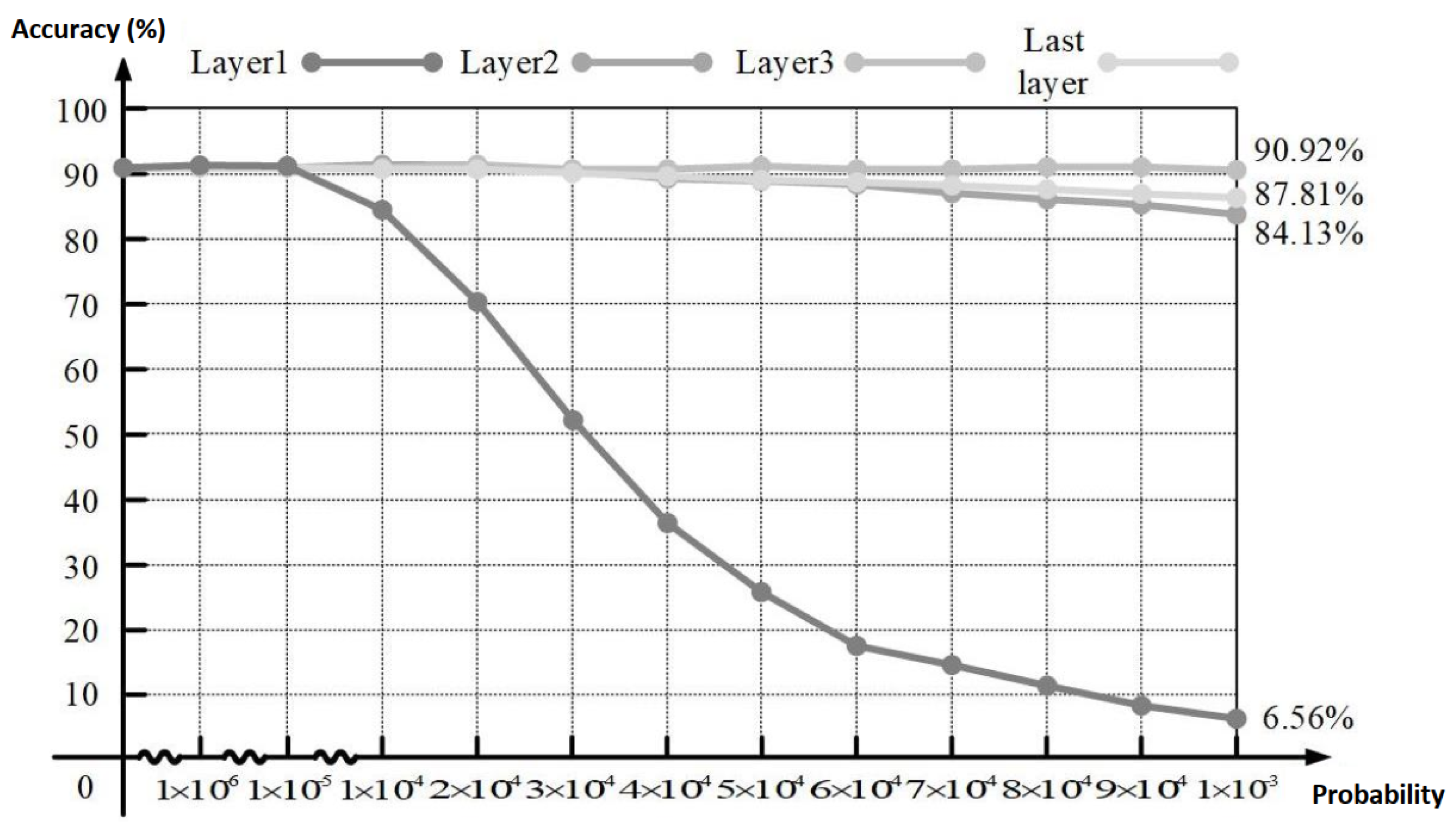
2.3. CNN Fault Tolerance Analysis

Convolutional neural networks (CNNs) inherently possess a certain degree of resilience against single-event upsets (SEUs). The most frequent operations in neural networks are convolution and pooling. The convolution operation consists of multiplying weights by sliding window data and accumulating the results. Both the input/output data and the computational process can be affected by SEUs. However, convolution operations are often followed by data quantization. For example, in 16-bit quantization, values greater than 32,767 or less than −32,768 are truncated, which helps to mitigate computational errors to some extent.
Quantized Value = 32 , 767 if x > 32 , 767 32 , 768 if x < 32 , 768 x otherwise
Additionally, convolution operations are usually followed by activation functions, such as ReLU or LeakyReLU. Whether an SEU-induced error propagates to the next stage depends on the sign of the value. If the value is positive, the error will remain in the model; if the value is negative, the activation function will output zero, preventing the error from affecting subsequent computations. This mechanism helps inhibit the propagation of errors to a certain extent.
ReLU ( x ) = max ( 0 , x )
LeakyReLU ( x ) = x if x 0 α x if x < 0
Pooling operations downsample feature maps. Max pooling with a window size of n and a stride of n can compress the feature map by a factor of n 2 . After performing the pooling operation, the probability of eliminating SEU-induced errors present in the input feature map is n 2 1 n 2 . As n increases, the probability of error elimination approaches 1, effectively preventing errors from propagating through the network.
Thus, CNNs naturally possess fault-tolerant capabilities during inference through operations such as quantization, activation, and pooling. These mechanisms help mitigate and eliminate computation errors caused by SEUs, enhancing the model’s stability and reliability in practical applications.
To validate the above points, we tested the resilience of the ResNet18 model against SEUs under a 16-bit quantization scheme. The experiment simulated SEU injections via software by introducing bit flips in the convolution layer’s output data at a constant probability to mimic the operational upsets in the accelerator. We also simulated the accumulation of errors due to long-term operation by gradually increasing the SEU probability. The ResNet18 model was trained on the NWPU−RESISC45 remote sensing dataset and achieved a Top−1 accuracy of 90.67% in the absence of SEUs, shown as Figure 3. The experiments were conducted on a test set of 1575 images, where errors were injected into the output data of all neural network layers.
The above research indicates that neural networks inherently possess fault tolerance for small amounts of errors. If the deviation between a feature map affected by SEUs and a feature map without errors is small, and timely error correction prevents error accumulation, it will not impact the final detection results. Therefore, when designing fault tolerance mechanisms, partial fault tolerance can be implemented based on the sensitivity of different modules to SEUs, thereby reducing the resource overhead associated with fault-tolerant design.

2.4. CNN Accelerator Design

In this paper, we designed a convolutional neural network (CNN) accelerator driven by instructions based on FPGA. The overall architecture of the accelerator is shown in Figure 4, and it consists of two parts: the instruction generation architecture on the PC side and the parallel computation architecture on the FPGA side. The instruction generation architecture serves as the control core of the accelerator, capable of compiling the computational processes of the network model into a sequence of binary instructions. The parallel computation architecture is the computational core of the accelerator, responsible for interpreting the binary instructions and driving each module to complete the corresponding calculations based on the interpretation results.

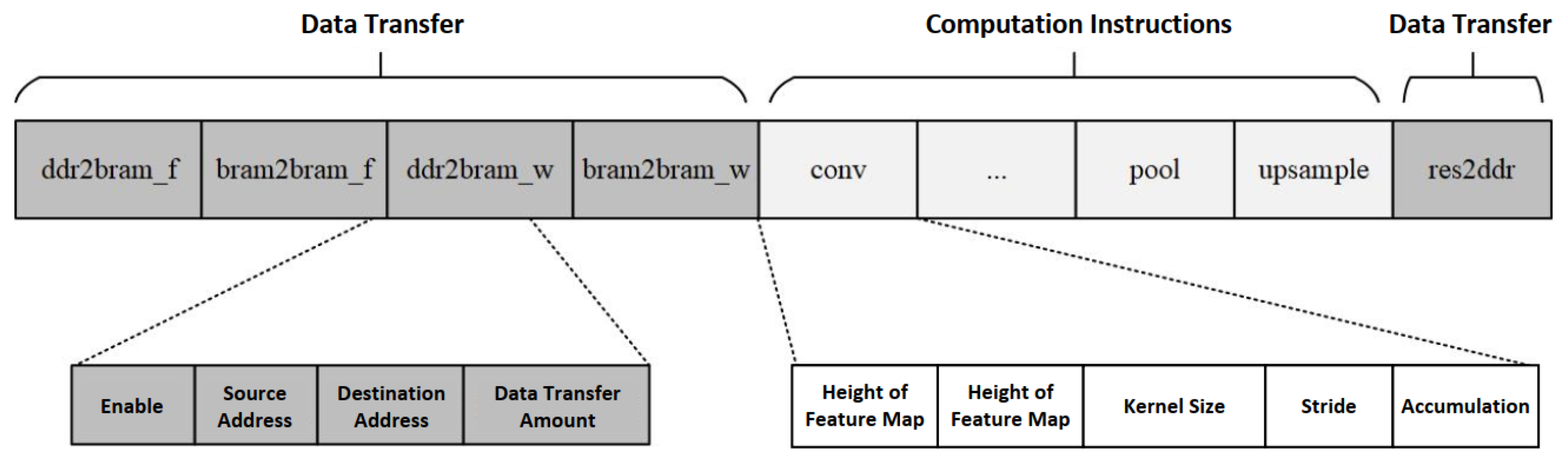
2.4.1. Instruction Encoding Design

The FPGA-based CNN accelerator functions similarly to a coprocessor, requiring the design of control logic to effectively coordinate with the CPU. The Very Long Instruction Word (VLIW) architecture, proposed by Josh Fisher in the early 1980s [31], is based on the idea of encapsulating multiple independent instructions into one very long instruction word. Correspondingly, multiple arithmetic logic units (ALUs) within the processor can execute these instructions simultaneously. A CNN accelerator typically consists of functional modules, such as convolution, pooling, and upsampling, which operate independently of each other, making it well suited to the VLIW architecture. This paper analyzes the CNN architecture and designs a VLIW to control the CNN accelerator. The forward propagation process of the network model is compiled into a sequence of multiple instructions. In the accelerator, specific modules interpret these instructions into control codes, which drive each functional module to perform the necessary computations and complete the network model’s forward propagation.
CNNs have a strict hierarchical structure with a well-defined data flow between layers. When mapped to the FPGA, this means that the execution of different operator modules follows a strict sequence. To maximize the advantages of FPGA’s parallel computing capabilities, this paper combines the control information of all modules in the accelerator into a single instruction, which is decoded in the FPGA and distributed simultaneously to all operator modules for parallel execution. To simplify the instruction design and facilitate subsequent decoding and execution, the VLIW uses fixed-length operation codes and fixed-length instruction codes. The design of the VLIW is shown in Figure 5, comprising data transfer instructions and computation instructions. Data transfer instructions handle on-chip data transfers and interactions between on-chip cache and off-chip DDR, while computation instructions control the enabling and specific operations of each functional module.
The instruction encoding format designed in this paper is shown in Table 1, with a total length of 636 bits. Data transfer is implemented through five instructions dedicated to memory access. The instruction names specify the source and target storage types as well as the data types. The storage types are divided into off-chip memory DDR and on-chip cache BRAM, and the data types are divided into feature maps (f) and weights (w). There are a total of nine computation instructions, among which the conv, pool, and upsample instructions are executed concurrently by different functional modules. The instruction encoding includes the necessary parameter information for each module.The bias, quant, and acti instructions are used to process the convolution results, with the instructions primarily containing control information. For example, bias includes bias data, quant includes the quantization factor and shift information, and acti specifies the type of activation function. The blockwise, short, and route instructions also involve memory access. Blockwise is used to control the merging of blockwise convolution results, short indicates whether the current network layer involves a shortcut operation, and route specifies whether the current network layer involves a routing operation.

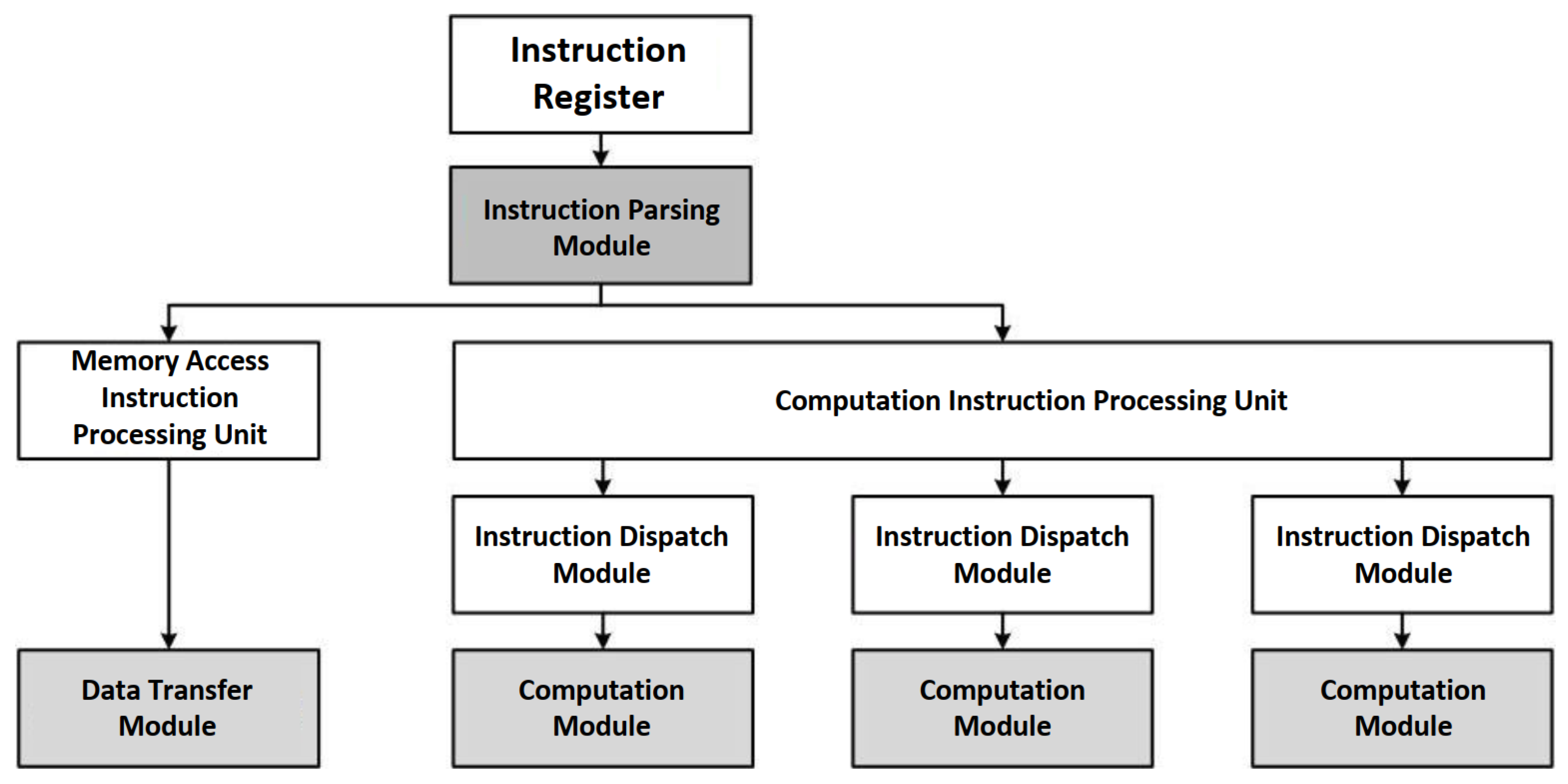
2.4.2. Accelerator Design

The CNN accelerator designed in this paper consists of several modules, including instruction parsing, data transfer, convolution computation, convolution result processing, pooling, and upsampling. The accelerator’s computation process is controlled by the instruction parsing module, which determines whether each module is enabled and retrieves the necessary parameters for operation based on the parsed binary instruction. Once the control parameters are received, each module enters a waiting state and only begins execution upon receiving the data stream. After the current module completes its computation, the results are sent to the next module via First-In-First-Out (FIFO) memory to trigger the next module’s computation.

Instruction Parsing Module
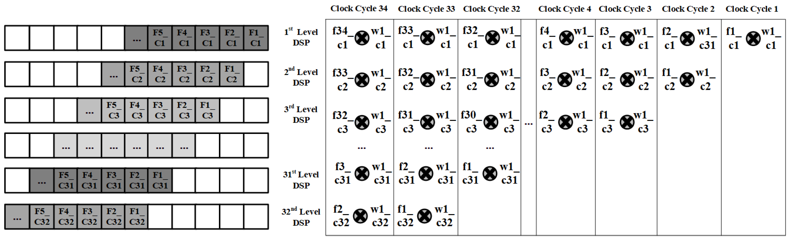
The instruction processing procedure is critical to the correct execution of tasks by the CNN accelerator. The process consists of five stages: Instruction fetch, Decode, Memory access, Execution, Write-back. The instruction fetch and decode stages are handled by the instruction parsing module, memory access and write-back are managed by the data transfer module, and execution is handled by the computation modules. The instruction parsing module has two main functions: instruction decoding and distribution. The binary instruction set generated by encoding the network model is stored in on-chip memory in the order of execution. When the CNN accelerator is initiated, the instruction parsing module sequentially reads and decodes the instructions stored in the cache.
Each binary instruction is 636 bits in length and contains both the data transfer information required for the accelerator’s operation and the control information for all functional modules. The overall structure is shown in Figure 6.
After splitting the binary instruction based on offsets, the data transfer instructions are parsed by the memory access instruction processing unit, while the computation instructions are parsed by the computation instruction processing unit. These units then send the data transfer information and control signals to the respective functional modules. Once the accelerator starts executing the computations, the instruction parsing module begins reading and decoding the next instruction, thus forming an instruction processing pipeline. When all the data for the current instruction have been processed, the computation results are written back to off-chip DDR, signaling the completion of the current instruction.

Convolution Module

The convolution module is the computational core of the CNN accelerator. In this design, 16 convolution units were implemented using the DSP resources of the FPGA. Each unit consists of 32 cascaded DSPs. The first DSP in each convolution unit is configured to perform an A × B operation, executing the multiplication of two 16-bit fixed-point numbers. The remaining DSPs are configured for the A × B + P C I N operation, accumulating the results of the previous stage, forming a 32 × 16 systolic array.
As shown in Figure 7, the 32 rows of the systolic array correspond to the 32 channels of the feature map, while the 16 columns correspond to 16 sets of weight parameters. The accelerator system operates at a clock frequency of 100 MHz, while the DSPs can run at frequencies up to 800 MHz. To maximize the computational capacity of the DSPs, the systolic array is set to run at 200 MHz. Surrounding each DSP, two weight caches are configured, forming a ping-pong buffer. These buffers load weight data at the system frequency of 100 MHz. In each clock cycle, the systolic array reads from one of the buffers to perform the convolution calculations, enabling two sets of 32 × 16 convolution operations to be completed simultaneously in one system clock cycle.
Each convolution unit in the systolic array uses a cascading configuration of 32 DSPs. The parallel acceleration of convolution depends on the architecture of the systolic array. In the systolic array, the first level requires A × B operations, and the other levels require A × B + P C I N operations. Each level of DSP is configured according to this mode to achieve parallel acceleration of convolution operations. If the data from all 32 channels of the input feature map were to be fed into the array at once, the computation for all channels would be completed within a single clock cycle, preventing accumulation from taking place. Therefore, it is necessary to rearrange the input feature map data. The data rearrangement process and specific timing are shown in Figure 8.
In the first system clock cycle, the data from the first channel of the first pixel in the feature map are input into the first row of the systolic array, where they undergo multiplication with the corresponding weight data. In the second system clock cycle, the data from the second channel of the first pixel are input into the second row of the systolic array and undergo multiplication with the weight data, then accumulate with the result from the first row. At the same time, the data from the first channel of the second pixel are multiplied by the weight data in the first row. In other words, the data from the Nth channel of the feature map must be delayed by N 1 clock cycles before being input. With this design, there is no output during the first 31 clock cycles, but starting from the 32nd clock cycle, output data are generated in each subsequent clock cycle.
Each clock cycle’s output data from the systolic array corresponds to the result of a 1 × 1 convolution operation. To perform larger convolution operations, the output data must be accumulated. The accumulation process is controlled by the instruction that dictates the clock cycles for accumulation. If the accumulation signal is disabled, the output result is not delayed, and the systolic array defaults to performing 1 × 1 convolution. When the accumulation signal is enabled, the clock cycles for accumulation are determined by the size of the convolution kernel. For example, for a 3 × 3 convolution operation, the array output data must be accumulated over 9 clock cycles to obtain the final convolution result.

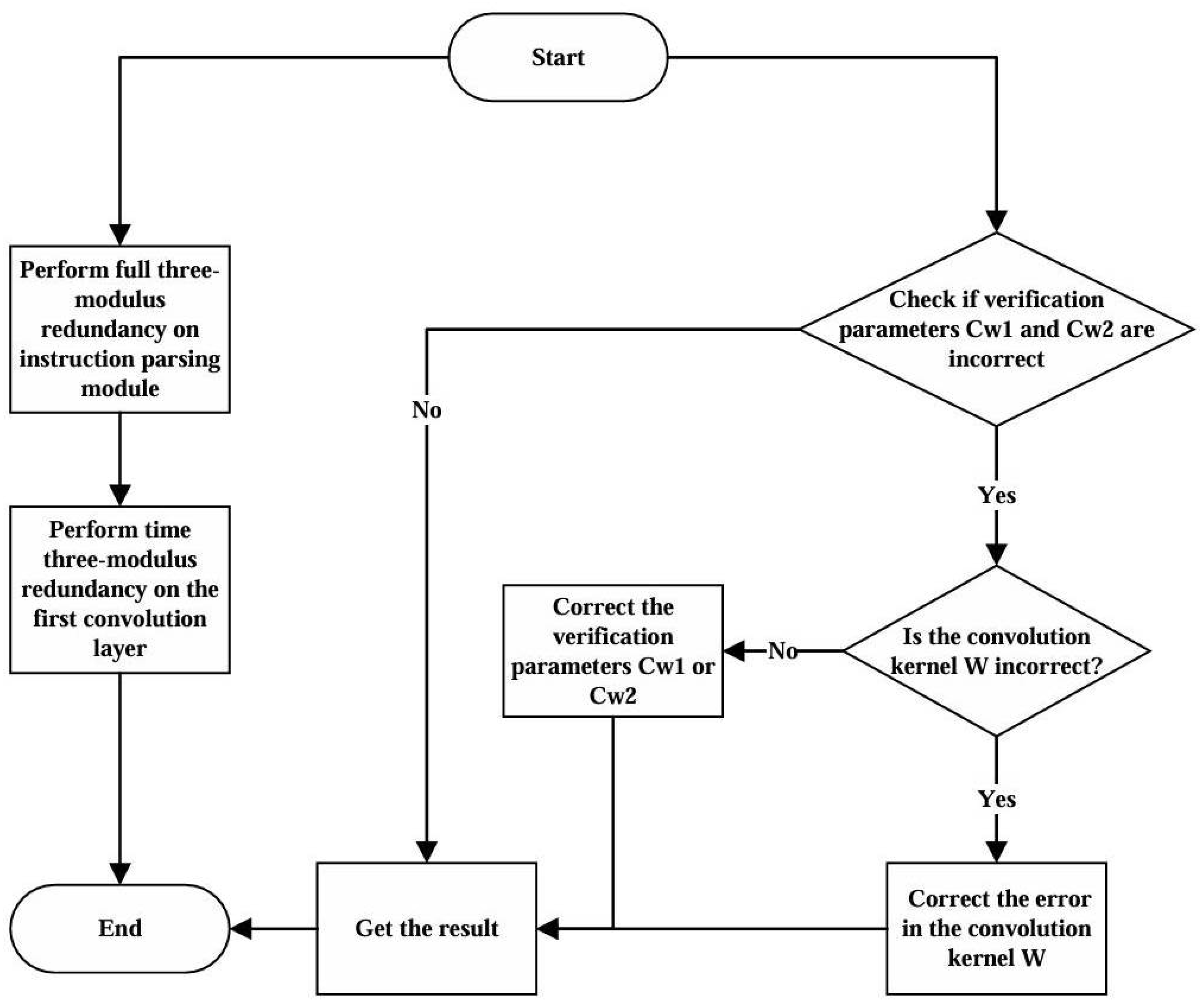
2.5. Fault Tolerance Design

Considering the need for single-event upset (SEU) resilience in spaceborne computing platforms, this paper introduces fault tolerance designs based on the FPGA CNN accelerator described in Section 2.4. In the redundancy design proposed in this paper, the approach is bifurcated into static and dynamic components. Static redundancy pertains to the redundancy design for weight parameters. We have introduced a per-channel weight parameter error correction scheme, the specifics of which are elaborated in Section 2.5.1. Dynamic redundancy, on the other hand, is implemented during the inference execution. We have initially applied full triple modular redundancy (TMR) to the accelerator’s instruction parsing module, which is relatively independent and features straightforward logical functionality; this constitutes a finer-grained redundancy approach, as discussed in Section 2.5.2. Subsequently, we have applied a coarser-grained temporal triple modular redundancy to the first convolutional layer, which significantly influences the outcome. This involves the repetitive computation of the first convolutional layer thrice, with each computation encompassing a set of instructions, as detailed in Section 2.5.3. Upon the conclusion of the computations, a voting mechanism is employed to ascertain the final result, thereby effectuating a fault-tolerant design. The flowchart illustrating this process is presented as follows in Figure 9:

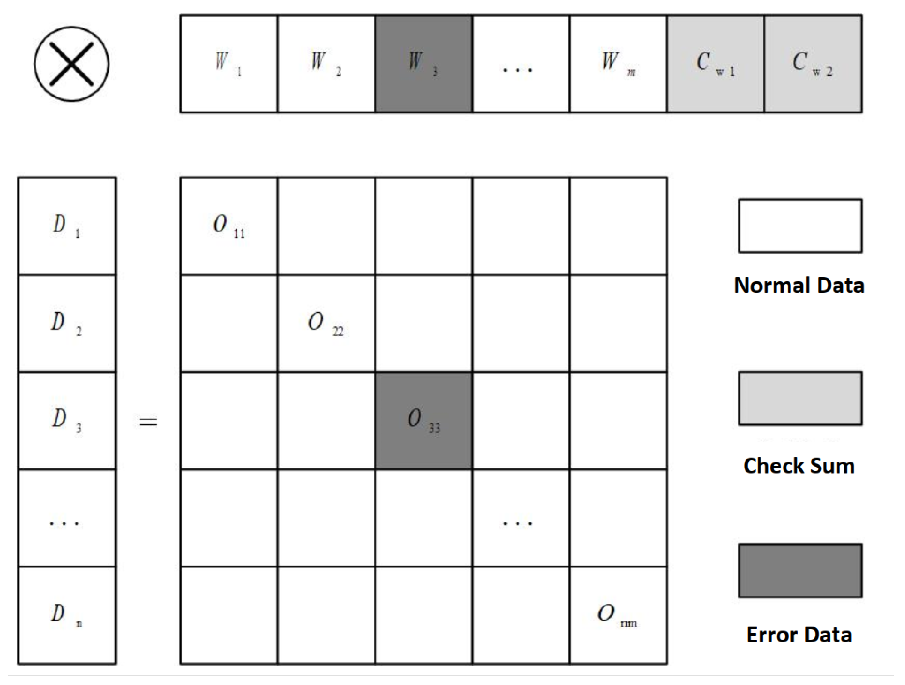
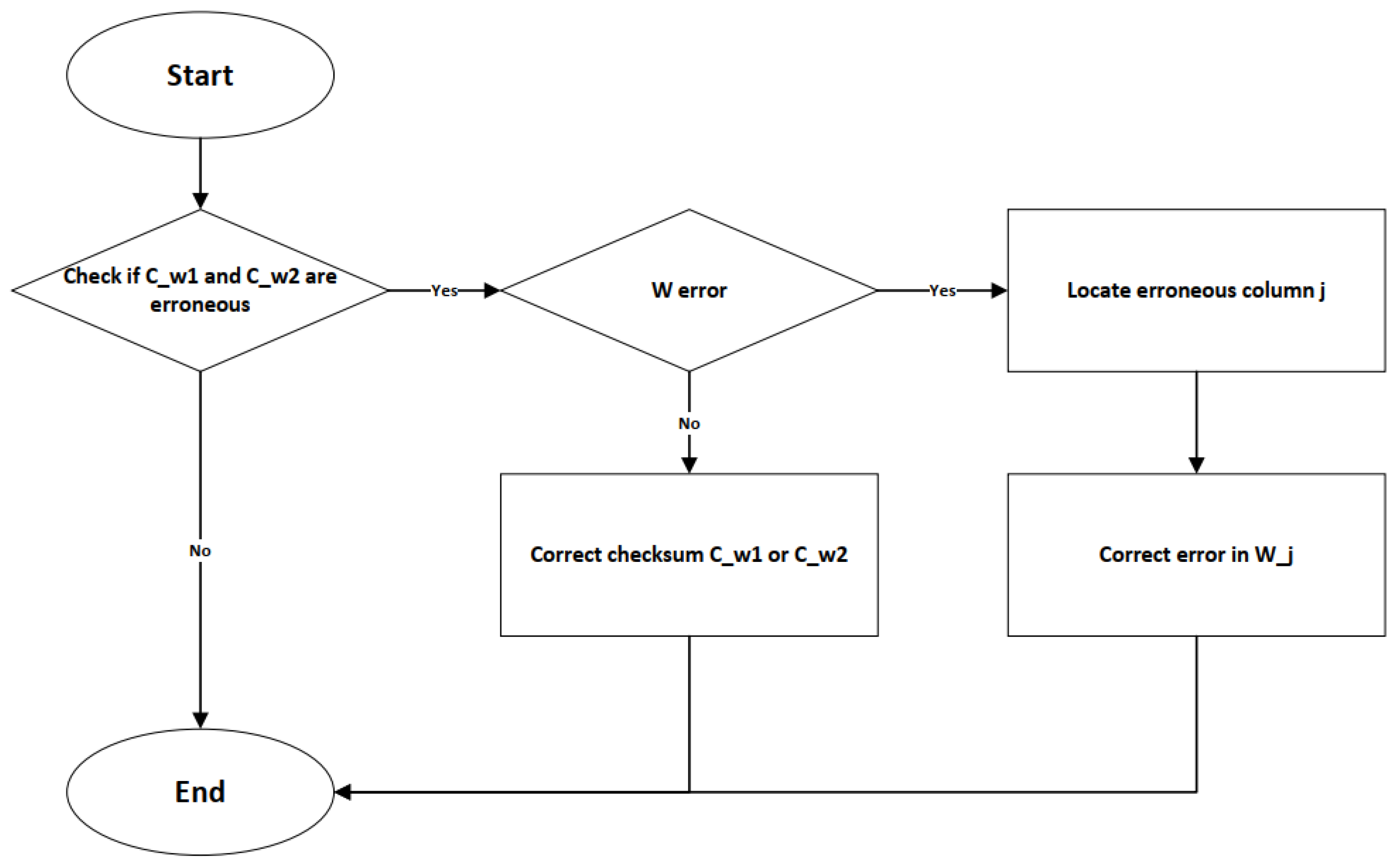
2.5.1. Fault Tolerance Design for Model Parameters

The parameters of a neural network model primarily include weight parameters and feature map parameters. During the operation of the accelerator, the images processed in each inference are different, so the feature map parameters are only affected by single-event upsets (SEUs) and do not face the problem of error accumulation. Since the probability of SEUs is low, errors in the feature map parameters can generally be ignored. In contrast, the weight parameters are shared across all inference processes, making them susceptible to cumulative errors over long-term operation. Given that the weight parameters are fixed and unchanging, their distribution can be pre-computed, and checks can be performed during inference to ensure the correctness of these parameters.
This paper proposes a channel-wise weight parameter error correction scheme. As shown in Figure 10, let D R C h × H × W represent the input feature map for a channel-wise convolution, where D n R H × W represents a single channel of the input feature map. W R C h × R × R represents the convolution kernel parameters for the channel-wise convolution, with W m R R × R representing a single channel of the convolution kernel. If an error occurs in one of the parameters of the convolution kernel W, it will result in an error O i i in the output feature map. Therefore, it is necessary to correct the weights in advance. The calculation of the check parameters C w 1 and C w 2 is shown in Equation (4).
C w 1 = m = 0 c h 1 W m , C w 2 = m = 0 c h 1 m W m
The channel-wise weight error detection and correction process is shown in Figure 11. Before performing the convolution operation, it is necessary to first validate the parameters C w 1 and C w 2 . If both C w 1 and C w 2 are incorrect, it indicates that a parameter W j in the weight matrix W is erroneous. Based on the values of C w 1 and C w 2 , the erroneous weight W j can be identified and corrected before proceeding with the convolution operation. If only one of C w 1 and C w 2 is incorrect, it indicates that only the checksum is faulty, and the erroneous checksum can be corrected accordingly.
This error correction scheme is only effective for cases where a single parameter in the weight matrix is faulty. For situations where multiple parameters are erroneous simultaneously, the scheme can detect errors but cannot correct them. However, since weight parameter errors during operation are promptly corrected, there is no risk of error accumulation. Additionally, the probability of multiple blocks within the same convolutional layer experiencing errors during a single inference is extremely low, meaning the correctness of weight parameters is essentially guaranteed.

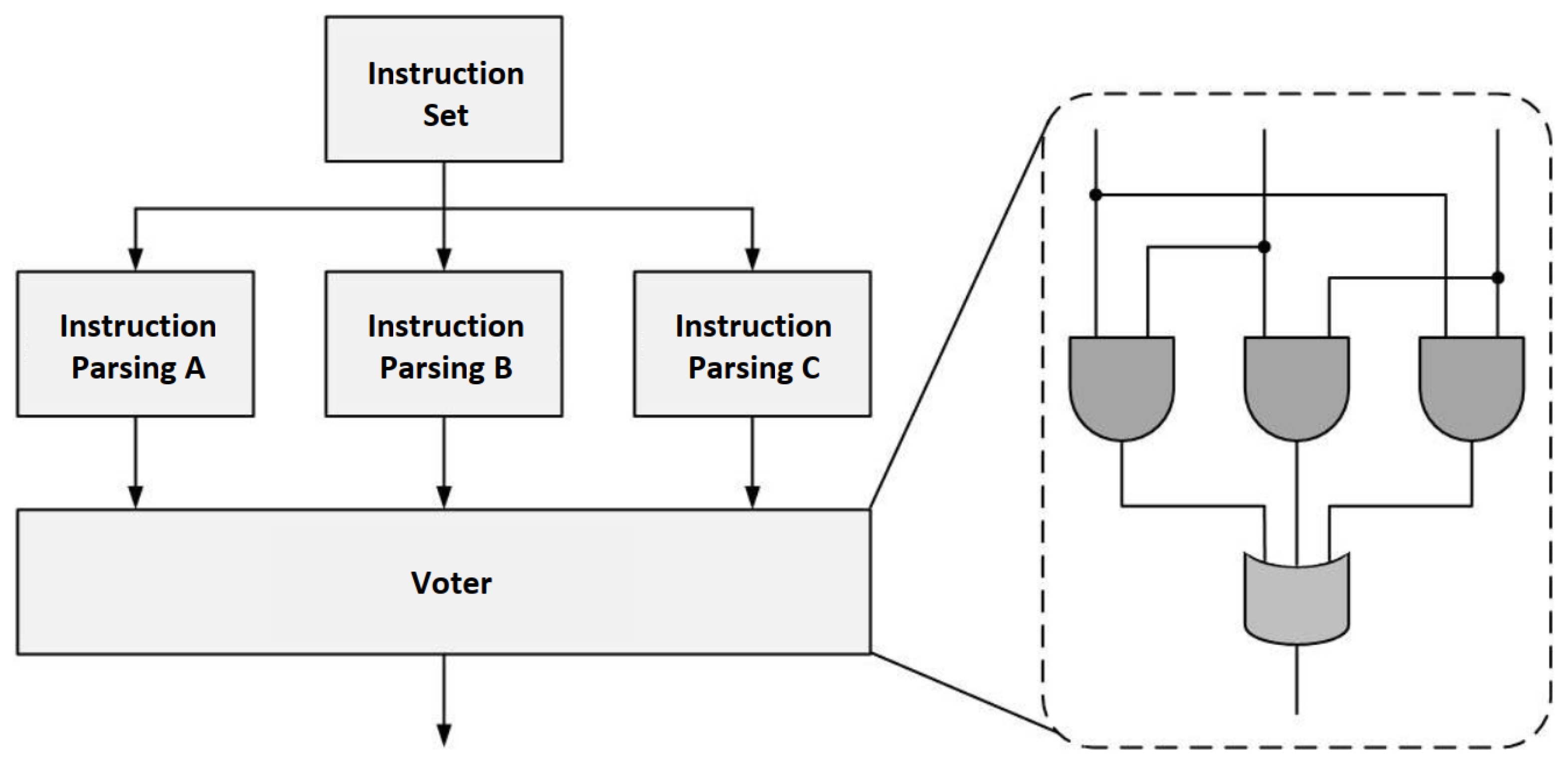
2.5.2. Fault Tolerance Design for Accelerator Control

The CNN accelerator is composed of several independent modules, including instruction parsing, data transfer, and computation modules for convolution, pooling, etc. The instruction parsing module, as the control core of the accelerator, is responsible for decoding instructions, passing parameters to the computation modules, and controlling the data transfer module to move data from off-chip DDR to each module for computation. Therefore, this section primarily analyzes the fault tolerance of the instruction parsing module, which is crucial for accelerator control.
Direct SEU injection experiments in hardware are challenging, so this paper simulates the interference caused by solar radiation on the instruction parsing module by directly flipping bits in the binary instructions. During the inference of each image, the instruction parsing module needs to decode and dispatch hundreds of instructions. Assuming only a single bit is flipped in one instruction during the inference process of each image, the experimental results for 1575 test images are shown in Figure 12. In 16.4% of cases, the images were correctly classified, though with some loss in accuracy. In 40.9% of cases, incorrect classification results were obtained, and in 42.7% of cases, the system crashed, producing no classification results at all.
Through experiments, it was observed that the instruction parsing module is highly sensitive to SEU (single-event upset) errors. This is because the instructions not only control various functional modules of the accelerator but also involve accessing memory spaces. Errors in the instructions can disrupt the computational process of the network model and may even lead to erroneous overwriting of data in the memory, resulting in unpredictable system failures. Therefore, the instruction parsing module in the accelerator must be designed with fault tolerance.
The operation of the instruction parsing module is relatively independent, and its logical functionality is simple, consuming only 6547 LUT resources. As a result, this paper adopts a triple modular redundancy (TMR) approach to harden the instruction parsing module. As shown in Figure 13, during the operation of the accelerator, each binary instruction is simultaneously parsed by three instruction parsing modules. The results of the parsing are filtered through a voter, which ensures that the correct control parameters are sent to the corresponding computation modules, thereby ensuring the proper functioning of the accelerator.

2.5.3. Fault Tolerance in Computation

Computation fault tolerance is designed to reduce errors generated during the network model inference process. This section experimentally analyzes the sensitivity of various stages in model inference to SEUs and proposes fault tolerance designs for the most sensitive stages based on the experimental results.
The same ResNet18 image classification model was used in the experiments, conducting SEU tests on 1575 images from the test set. The rationale for selecting ResNet18 lies in its status as a relatively compact and structurally straightforward deep learning model. It comprises a moderate number of layers and parameters, which facilitates easier management and testing during the fault tolerance design process. Despite its smaller size, ResNet18 has demonstrated commendable performance across a variety of image recognition tasks, making it an ideal candidate for evaluating the impact of fault tolerance designs on performance. Furthermore, the widespread adoption and recognition of ResNet18 in the field of computer vision render the findings more comprehensible and comparable. The bit-flip probability was gradually increased from 1 × 10 7 to 1 × 10 3 . Random bit flips were applied to the output data of the first three layers and the last layer of the model. The fault tolerance of each neural network layer was evaluated by measuring the model’s average precision loss caused by these bit flips.
The experimental results are shown in Figure 14. For the model’s first layer, when the error accumulates to 1 × 10 5 , the model’s accuracy starts to drop sharply. When the error accumulates to 1 × 10 3 , the classification accuracy drops to 6.56%. This shows that the first layer of ResNet18 is highly sensitive to SEUs. The second most sensitive layer is the model’s second layer, where the classification accuracy drops to 84.13% when errors accumulate to 1 × 10 3 . This is followed by the last layer, where accuracy decreases to 87.81%. In contrast, the third layer of the model is almost unaffected by SEUs.
This indicates that the middle hidden layers of the network model have strong fault tolerance, and data errors have minimal impact on the computation results. The first layer of the model directly processes the raw image data and typically has the largest number of parameters. Therefore, it has the highest probability of experiencing SEUs, and errors in this layer have the most significant impact on the computation results.
This paper further investigates the impact of network model depth on the fault tolerance of the model by testing models of the same type but different depths. Since a noticeable impact on model accuracy only occurs when errors accumulate to 1 × 10 4 , the experiment tested ResNet models with different depths (18, 34, 50, 101, 152) by applying random bit flips at a fixed probability of 1 × 10 4 to the computation results of the first layer of each model. The experimental results are shown in Figure 15.
The results indicate that as the depth of the network model increases, the accuracy loss caused by SEUs gradually decreases. This shows that the deeper the model, the higher the probability that errors in the data are mitigated during propagation, which aligns with the previous analysis. Therefore, for models with fewer layers, it is necessary to implement fault tolerance in the computations of the first convolutional layer.
For fault tolerance design in convolution operations, the mainstream solution is to use triple modular redundancy (TMR) for hardening. However, convolution operations rely heavily on the systolic array in the accelerator, which occupies the majority of the accelerator’s resources. Implementing TMR would significantly multiply the resource consumption of the accelerator.
Therefore, this paper proposes a fault-tolerant scheme using temporal TMR, where the first convolutional layer of the model is computed three times consecutively using the systolic array. This fault tolerance approach is implemented by modifying the model instructions. As shown in Figure 16, the instruction for the first convolutional layer is executed three times in succession, resulting in three sets of computation results. A selector then chooses the correct output to produce the final result of the convolution layer.

3. Results

In this study, the convolutional neural network accelerator was implemented at the RTL level based on Xilinx’s Virtex 7 FPGA VC709. Two sets of DDR controllers were instantiated, each connected to 4 GB of external DDR3 memory, supporting 16-bit ECC error checking. The data and weights in the accelerator are quantized in 16-bit integers. The resource consumption of the accelerator is shown in Table 2.

3.1. Hardware Accelerator Performance Comparison

The performance of the accelerator was tested using the ResNet18 image classification model. Before testing, the model must be encoded and parameters quantized on the PC. The quantized 16-bit fixed-point weights and binary model encoding files are then transmitted to a fixed address in the FPGA’s off-chip DDR via PCIe.
The process of image classification using the accelerator, as shown in Figure 17, can be divided into three main stages:
(a)
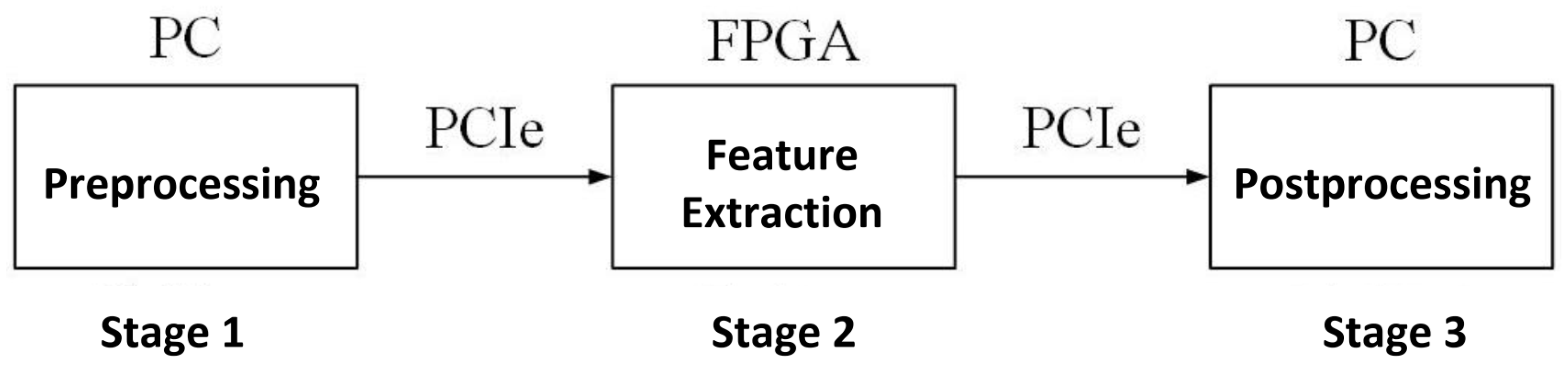
Image Preprocessing: The PC reads the raw image and adjusts its size to [ 1 ,   3 ,   256 ,   256 ] through scale transformation. The processed image data are then transferred to the FPGA’s DDR via PCIe.
(b)
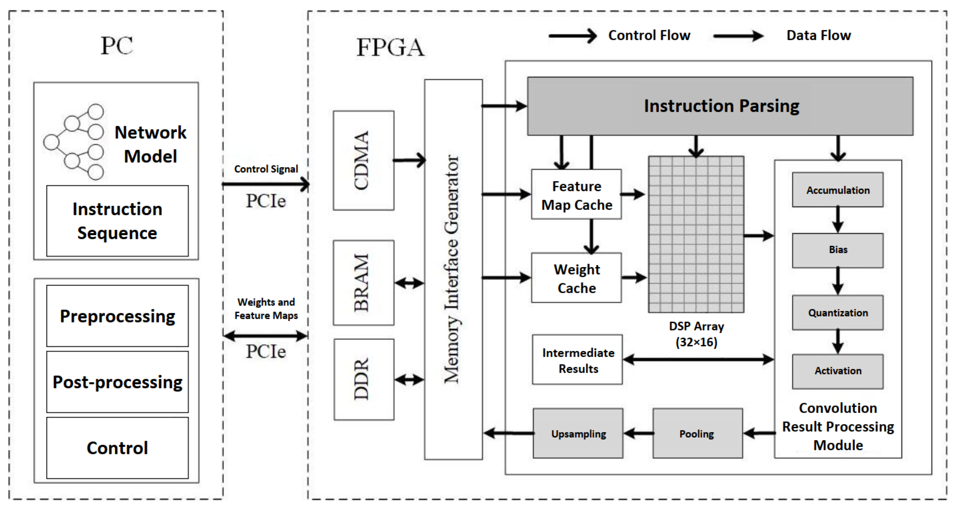
Image Feature Extraction: The instruction parsing module sequentially reads binary instructions from a fixed address. Based on the parsed results, feature map data and weight data are transferred from DDR to the computational units for processing. Once the computation is completed, the data are written back to DDR.
(c)
Image Postprocessing: The feature extraction results are transferred back to the PC via PCIe, where postprocessing is performed. The classification result is printed based on the computed probabilities.
This flow outlines the use of the accelerator for efficient image classification.
Figure 17. Accelerator operation process.
Remotesensing 17 00069 g017
The performance of the accelerator designed in this paper is compared with related works in Table 3. The Theoretical Peak Throughput (TPT) is calculated based on the working frequency and the number of DSPs in the accelerator. The Actual Peak Throughput (APT) is the peak value recorded during the operation. The Computing Resource Efficiency (CRE) is the ratio of the actual peak to the theoretical peak throughput. Performance Density (PD), defined as the ratio of the actual peak throughput to the number of DSPs, is particularly significant in evaluating the computational efficiency of accelerators under resource-constrained environments, such as spaceborne systems. A higher PD value indicates that the accelerator achieves greater computational performance for each DSP utilized, which is critical for satellite platforms where hardware resources (e.g., DSPs) are extremely limited due to power, area, and thermal constraints. Both the XC7VX980T FPGA and the VC709 Evaluation Board are products of Xilinx, Inc., a leading provider of advanced programmable logic devices and hardware development platforms. Xilinx is headquartered in San Jose, California, USA, and is recognized for its innovative contributions to the field of programmable logic and adaptive computing.

3.2. Fault Tolerance Performance Comparison

Since the impact of SEUs on feature map parameters can be ignored, no fault tolerance design was implemented for feature maps. Therefore, this section primarily tests the fault tolerance effectiveness for weight flips and computation flips.

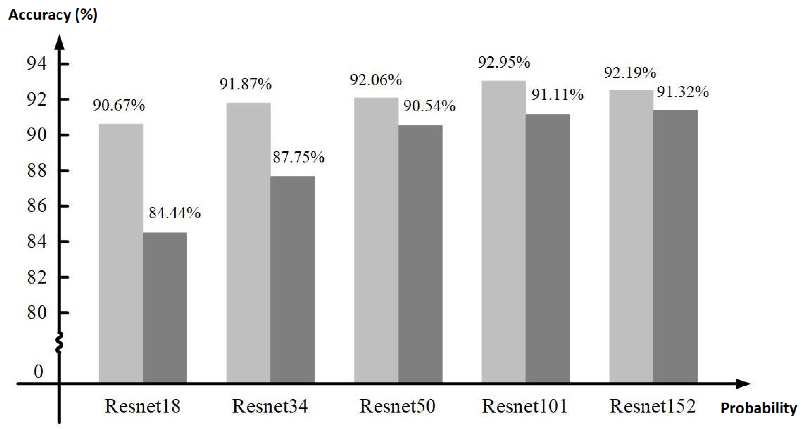
3.2.1. Weight Fault Tolerance Comparative Analysis

For weight parameters without fault tolerance design, a single-event upset (SEU) simulation test was conducted. For the model employing the channel-wise weight fault tolerance design, additional experiments were conducted to evaluate its robustness under varying weight flip probabilities, and the results are shown in Figure 18.
As shown by our results, this improvement stands in stark contrast to the baseline model without fault tolerance. For weight parameters without fault tolerance, the classification accuracy begins to noticeably decrease once the error accumulation reaches 3 × 10 4 , dropping to around 80% at that point (as indicated by the dashed line in the figure). In contrast, with our channel-wise redundancy scheme, the accuracy remains above 80% until the error accumulation reaches 5 × 10 4 . This demonstrates that our fault tolerance approach substantially delays the onset of significant accuracy degradation, maintaining a slower decline as the error rate increases.
Moreover, when the error injection probability escalates to 1 × 10 3 , the baseline accuracy falls to roughly 34.76%, while our fault-tolerant model preserves an accuracy of about 62.24%. This nearly 30 percentage point advantage at the highest tested error injection rate further highlights the effectiveness of the channel-wise redundancy design in mitigating the impact of single-event upsets on model accuracy.
To confirm the robustness of the fault tolerance design, we employed a statistical validation method by conducting repeated tests thirty times at different error injection rates. The results are presented in the following table:
From Table 4, it can be observed that as the error injection rate increases, the model’s mean accuracy shows a clear decreasing trend, consistent with the expected behavior under increasing error conditions. Notably, the Min Accuracy and Max Accuracy remain within a relatively narrow range for each error injection rate, particularly at lower rates, indicating that the model exhibits strong stability across multiple tests in these conditions. Furthermore, the inclusion of standard deviation and confidence intervals further highlights the robustness of the results. The small standard deviations, particularly at lower error injection rates, suggest minimal variability in the model’s performance, reinforcing its consistency. As the error injection rate increases, the confidence intervals widen, reflecting a greater dispersion in the results, which aligns with the expected degradation in model performance due to higher error rates. These observations demonstrate the model’s resilience to low-level errors and its predictable degradation under more challenging conditions.

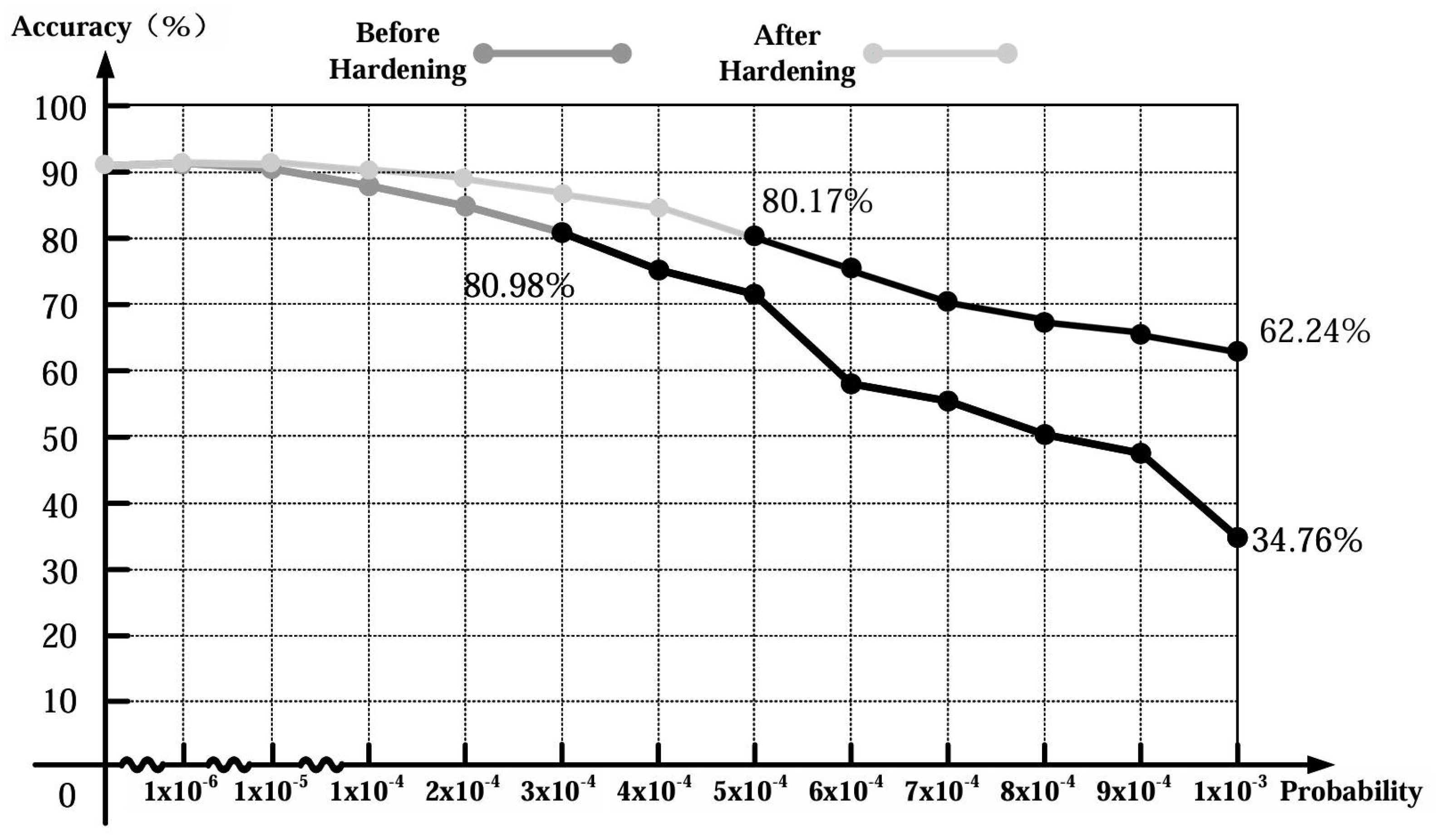
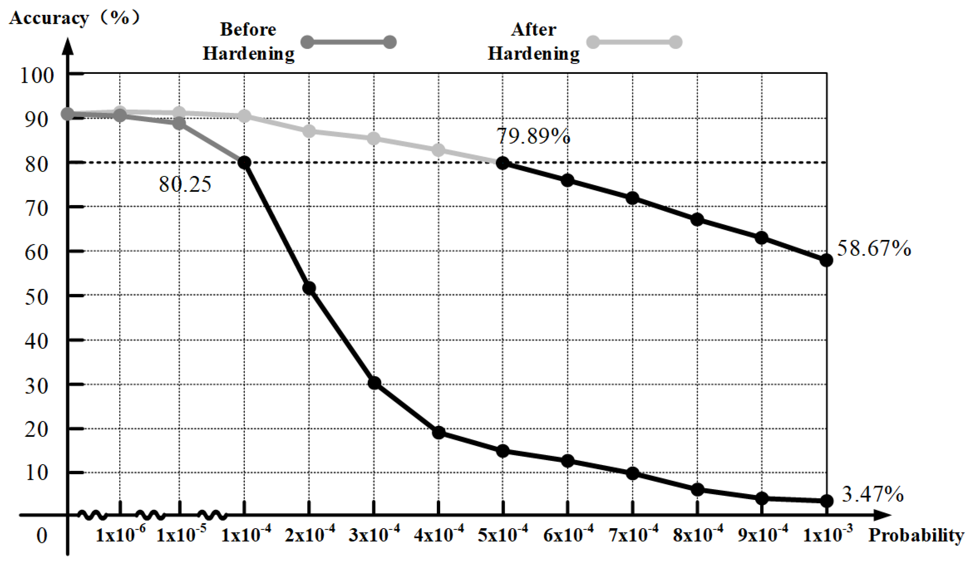
3.2.2. Computation Fault Tolerance Comparative Analysis

To evaluate the effectiveness of the computation fault tolerance design, this paper compares the accuracy of the original model with that of the model hardened using instruction-level triple modular redundancy (TMR). The experiment injected errors into the output data of all layers in the ResNet18 model to verify the fault tolerance of the entire model. As shown in Figure 19, both models—before and after the fault tolerance design—exhibit a decline in accuracy as SEU errors accumulate, but the rate of decline is significantly different.
For the model without fault tolerance, accuracy begins to drop when error accumulation reaches 1 × 10 5 , and the accuracy drops by approximately 10% at 1 × 10 4 . When error accumulation reaches 1 × 10 3 , the classification accuracy drops to 3.47%. In contrast, the accuracy of the model with fault tolerance declines much more gradually. Its accuracy does not decrease by 10% until the error accumulation reaches 5 × 10 4 , and even at 1 × 10 3 , the accuracy remains at 58.67%.
Based on the experiment, applying triple modular redundancy (TMR) to harden the first layer of the network model increased the error accumulation threshold by approximately five times before the model’s accuracy dropped by 10%. This indicates that the system’s operational time before encountering significant performance degradation due to SEU errors has been extended by five times, thereby mitigating the impact of SEUs on the model’s accuracy to a certain extent.
Similarly, in order to confirm the robustness of the fault−tolerant design, we used statistical verification methods and conducted thirty repeated tests at different error injection rates. The results are shown in the following table.
Examining Table 5, it is evident that as the error injection rate increases, the model’s mean precision steadily declines, which aligns with expected trends. However, after hardening, the model demonstrates significantly improved stability and resilience, as shown by the reduced variability across multiple tests. The strong clustering of Min and Max Precision values, combined with narrower confidence intervals, highlights the effectiveness of the proposed method in mitigating the impact of computational errors. These results emphasize the robustness and reliability of the approach, even under challenging conditions with high error rates.

3.2.3. Performance Comparison Before and After Fault Tolerance Implementation

To further elucidate the performance of the method proposed in this study, a comparison of processing time, resource consumption, and energy consumption metrics is presented. The results are summarized in Table 6:
In an exhaustive comparison of the original method, the TMR approach, and the method proposed in this paper, the latter has demonstrated marked advantages across multiple key performance indicators. While the TMR method does enhance system reliability, its disproportionately high costs in processing time, LUT, BRAM, and DSP utilization, as well as its greater energy consumption, may limit its applicability in resource-constrained scenarios. In contrast, the proposed method maintains processing times nearly on a par with the original approach, significantly reduces LUT consumption, and achieves far lower BRAM and DSP usage than the TMR solution. Notably, it also offers substantially improved energy efficiency. Taken together, these results indicate that the proposed method strikes a more favorable balance between performance and resource optimization, making it especially well suited for modern FPGA implementations where strict efficiency and hardware constraints are paramount.

4. Discussion

The results presented in the Results section offer a comprehensive evaluation of our proposed fault-tolerant design for spaceborne neural network accelerators. This discussion aims to elaborate on the significance of these findings, the benefits of our approach, and its implications for future space missions.

4.1. Performance Evaluation and Comparison

As detailed in Table 2. Our accelerator’s resource consumption is significantly lower than what would be required if a full triple modular redundancy (TMR) approach was adopted, which would push the LUT and BRAM resources to their limits, potentially causing timing issues and system instability.
The performance metrics detailed in Table 3 provide a clear comparison of our proposed accelerator against existing works. Work1 stands out with an impressive actual peak throughput (APT), computing resource efficiency (CRE), and performance density (PD), boasting a CRE of 98.2% and a performance density (PD) of 0.29. However, its high resource consumption, particularly in terms of LUT and BRAM, makes it less suitable for spaceborne environments where resources are constrained and power is a limited. The high resource consumption of Work1 could lead to potential timing issues and system instability, which are critical concerns in the context of space applications. Work 2 and Work 3, on the other hand, present lower CRE and PD figures, at 77.3%, 74.8%, and PD values of 0.15, 0.22, respectively. These works are more aligned with applications that have limited resources but still demand real-time performance capabilities.
Our accelerator, in contrast, excels across different models, achieving CRE of 92.0% for ResNet18, 94.1% for VGG16, and 88.7% for AlexNet, along with PD values of 0.37, 0.38, and 0.36, respectively. This demonstrates our design’s superior resource utilization and computational efficiency, allowing it to sustain high frame rates for both ResNet18 and AlexNet models, with rates of 56 FPS and 63 FPS, respectively. This is a testament to its excellent real-time processing capabilities, which are crucial for spaceborne applications.

4.2. Fault Tolerance Comparative Analysis

The analysis presented in this study provides a comprehensive evaluation of the fault tolerance capabilities of our proposed neural network accelerator design against single-event upsets (SEUs). The results, as depicted in Figure 18 and Figure 19, offer a clear perspective on the effectiveness of our fault tolerance strategies.
In the absence of fault tolerance design for weight parameters, the simulation test for SEUs demonstrates that the model’s accuracy remains largely unaffected at a weight flip probability of 1 × 10 7 . However, as the probability of flipping increases, a noticeable decrease in classification accuracy is observed once the error accumulation surpasses 1 × 10 5 . Notably, when the error accumulation reaches 3 × 10 4 , the classification accuracy experiences a decrease exceeding 10%.
Conversely, the implementation of a channel-wise fault tolerance scheme ensures that errors occurring at a flip probability of 1 × 10 7 are promptly detected and corrected. This proactive error correction mechanism precludes the accumulation of errors, thus preserving the high level of data accuracy within the neural network weights.
The comparison of accuracy between the original model and the model reinforced with instruction-level TMR reveals the tangible benefits of our computation fault tolerance design. The injection of errors across all layers of the ResNet18 model serves as a testbed for the fault tolerance of the entire system. It is evident that while both models exhibit a decrease in accuracy with accumulating SEU errors, the rate at which this decline occurs is markedly different. The comparison of accuracy between the original model and the model reinforced with instruction-level TMR reveals the tangible benefits of our computation fault tolerance design. The injection of errors across all layers of the ResNet18 model serves as a testbed for the fault tolerance of the entire system. It is evident that while both models exhibit a decrease in accuracy with accumulating SEU errors, the rate at which this decline occurs is markedly different.
These findings underscore the pivotal role of our fault tolerance design in bolstering the resilience of the neural network accelerator against SEUs. By enhancing the error accumulation threshold by approximately fivefold, our design significantly extends the operational lifespan of the system before significant performance degradation occurs. This is particularly critical in the context of spaceborne applications, where the reliability and longevity of computational systems are of paramount importance.
In conclusion, the fault tolerance analysis affirms the robustness of our neural network accelerator design against SEUs. The comparative analysis not only validates the efficacy of our weight and computation fault tolerance strategies but also accentuates their significance in the realm of spaceborne computing. Our design’s ability to maintain high levels of accuracy and operational stability, even in the face of SEU-induced errors, positions it as a leading solution for space applications where fault tolerance is non-negotiable.

4.3. Summary and Future Work

In conclusion, our accelerator design offers a robust solution tailored for spaceborne applications, achieving a remarkable balance between performance, resource efficiency, and fault tolerance. This research significantly contributes to the domain of spaceborne computing and establishes a new benchmark for the design of future spaceborne AI systems. The demonstrated potential to extend our design to multi-core and heterogeneous systems presents a promising avenue for future research, with the potential to yield more versatile and efficient computing solutions for spaceborne environments.
And for networks with varying architectures, fault tolerance designs will likely require adjustments to accommodate differences in layer count and parameter volume. In this paper, we propose a channel-level weight parameter error correction scheme that ensures the accuracy of the inference process by pre-validating weight parameters. In ResNet18, this approach effectively enhances the model’s robustness. However, as the depth and complexity of the model increase, such as in larger architectures like ResNet50 or DenseNet121, the number of channels and parameters grows significantly. This growth leads to a linear or super-linear increase in the computational and storage overheads associated with channel-level pre-validation. Consequently, the computational overhead increases, requiring more computational resources for pre-validation, which may impact overall inference speed. Additionally, storage overhead increases as extra space is needed to store validation information, especially in models with larger parameter counts. To address these challenges in larger and more complex models, different validation granularities across various layers can be considered. For example, pre-validating only critical layers or high-impact channels can reduce overall overhead. Alternatively, leveraging parallel computing resources could accelerate the pre-validation process, thereby minimizing the impact on inference speed. These strategies aim to balance the trade-off between fault tolerance and resource efficiency, ensuring that the model remains both robust and performant as it scales. In our accelerator control design, we employ TMR in the instruction parsing module to ensure the correctness of control parameters. As neural network architectures become more complex, the number and complexity of control instructions increase. Implementing TMR in more intricate instruction flows may lead to increased resource consumption, necessitating additional hardware resources. This is particularly significant in high-frequency instruction parsing scenarios where resource overhead is substantial. Moreover, multiple redundancies can introduce additional latency, especially in high-frequency operations, where the cumulative effect of latency can degrade overall performance. To mitigate these issues, dynamic redundancy adjustment can be considered, where the level of redundancy is adjusted based on real-time error rates and system load. For example, reducing redundancy when error rates are low can save resources, while increasing redundancy during periods of high error rates can enhance fault tolerance. Additionally, selective redundancy, where TMR is applied only to critical control paths or high-risk modules, can balance reliability with resource and latency overheads. These approaches can help maintain control parameter correctness without incurring excessive resource or performance penalties. And our existing computational fault tolerance method employs time redundancy and a voting mechanism by repeating the first layer convolution operation three times to achieve fault tolerance. Generally, this method does not significantly alter overhead. However, in deeper networks, the influence of the first layer’s computations may be either diminished or amplified, reducing the effectiveness of repeating only the first layer convolutions. Therefore, additional layers, such as layers towards the end or other critical sections of the network, can also be redundantly computed to improve overall fault tolerance. Expanding the fault tolerance mechanism to multiple layers ensures that errors occurring deeper in the network are also addressed, thereby enhancing the robustness of the entire model. Additionally, integrating selective redundancy based on the criticality of different layers or leveraging hardware acceleration to perform redundant computations more efficiently could further optimize the fault tolerance design. These enhancements aim to provide comprehensive fault tolerance across the network while managing the associated computational and energy costs.
Furthermore, different space missions impose varying requirements on computational performance, particularly when it comes to fault tolerance strategies. As highlighted in our previous discussion, missions like satellite navigation or target recognition prioritize low latency and high throughput, which require optimized computational performance while adhering to strict power budgets. In contrast, batch-processing tasks, such as terrain mapping or image analysis, prioritize resource efficiency to handle large datasets without compromising power consumption.
An important factor influencing fault tolerance design in space systems is the space environment, particularly the levels of radiation present in different regions of space. In environments with higher radiation intensities, such as deep space or Mars, the likelihood of bit flips and hardware malfunctions increases, requiring more frequent error correction mechanisms and potentially higher levels of redundancy to ensure system reliability. In these conditions, a more aggressive approach to fault tolerance may be necessary to account for radiation-induced errors, especially for long-duration missions where exposure to radiation can be prolonged and intense. Conversely, in regions with lower radiation levels, such as in low Earth orbit (LEO), the need for extreme fault tolerance strategies may be reduced. The lower likelihood of radiation-induced errors in LEO means that more lightweight error correction strategies might be sufficient, resulting in lower resource consumption. This would allow for a more efficient use of computational resources and power, ensuring that the system remains cost-effective without sacrificing performance. Adaptive fault tolerance techniques, which adjust the level of fault protection based on the system’s current exposure to radiation, could be employed to dynamically scale fault tolerance depending on the environment.
Therefore, to enhance the adaptability of our design, we envision an approach in which the system can detect radiation levels in real-time and adjust the fault tolerance mechanisms accordingly. For example, on missions to Mars or deep space, the system could activate higher redundancy levels and more aggressive error correction when radiation levels exceed certain thresholds. This includes applying global triple modular redundancy (TMR) across critical components, as well as implementing time-based TMR for key operations. In this approach, the system could apply time-based TMR simultaneously to several parts of the workload that are most sensitive, such as the initial and final convolutional layers, to ensure that errors in these critical stages are corrected efficiently. While in LEO (Low Earth Orbit) or less challenging environments, it could operate with lighter fault-tolerant measures. This adaptability ensures that the system remains resource-efficient while still providing the necessary reliability for critical tasks, whether in high- or low-radiation environments. Furthermore, different mission profiles necessitate a tailored approach to fault tolerance. For example, a Mars mission, with its high radiation exposure and long communication delays, may require more autonomous fault recovery systems, as real-time intervention may not be feasible. Meanwhile, missions in LEO can benefit from more frequent communications with ground control, allowing for rapid fault diagnosis and recovery interventions, thus reducing the need for extensive on-board fault tolerance measures.
Looking ahead, the scalability of our design to multi-core or heterogeneous systems is a pivotal direction for upcoming work. By distributing the neural network workload across multiple processing units, each optimized for specific tasks, we can further enhance system performance and fault tolerance. This extension could involve the development of dynamic workload distribution algorithms that intelligently allocate tasks to different cores based on their current load and the complexity of operations. Additionally, exploring inter-core communication protocols and interconnects that minimize latency and maximize throughput is crucial for the seamless operation of a multi-core system.

5. Conclusions

This paper proposes a fault-tolerant design method for a spaceborne convolutional neural network accelerator for space applications, aiming to meet the high reliability requirements of aerospace platforms for real-time data processing. The main contributions of this paper are reflected in the following aspects:
Combination of fault-tolerant design and FPGA acceleration: We designed an FPGA-based CNN accelerator architecture, which accelerates the reasoning process of neural networks by utilizing the parallel computing power of FPGAs. At the same time, considering the impact of single-particle single upset (SEU) in the space environment on computing, an effective fault-tolerant technology was proposed. This design enables neural networks to run efficiently and stably on aerospace platforms.
Partially optimized triple redundancy (TMR) scheme: This paper proposes a partially optimized TMR design scheme for SEU-sensitive modules. Different from the traditional full-module TMR design, this method only applies redundancy technology to the instruction parsing module, and adopts low-resource data verification and time redundancy strategies for parameter storage and accelerator computing, thereby controlling the additional resource consumption within 15%. This design effectively reduces resource consumption while ensuring system stability, adapting to the strict restrictions on resources and power consumption of aerospace platforms.
Significantly improved fault tolerance: Through SEU injection experiments, we verified that the proposed fault-tolerant design can significantly improve the tolerance to SEU-induced errors. Experimental results show that the design is five times better than the traditional solution in terms of fault tolerance, which greatly enhances the reliability of the system in the space environment.
Balance between real-time processing capability and resource efficiency: Experimental results based on the ResNet18 model show that the proposed accelerator, implemented on the VC709 platform at a frequency of 200 MHz, can achieve a real-time image processing speed of 56 frames per second (FPS). For the VGG16 model on the same VC709 platform at 200 MHz, our accelerator achieves a frame rate of 7 FPS. This matches the results reported in Work 3 [34] but significantly outperforms Work 1 [32], which achieves no reported frame rate despite using a more resource-intensive XC7VX980T platform. These comparisons underscore that our design achieves comparable performance on a resource-constrained platform with enhanced fault tolerance. For the AlexNet model, our design achieves 63 FPS on the VC709 platform, which is nearly three times higher than the 21 FPS reported in Work 2 [33]. This demonstrates a clear improvement in real-time processing capability, further solidifying the efficiency of our proposed design. Collectively, these results highlight that the proposed accelerator achieves a superior balance between real-time processing capability and resource efficiency across multiple network architectures. By systematically comparing against Work 1 [32], Work 2 [33], and Work 3 [34], our design showcases advancements in throughput, performance density (PD), and fault tolerance under constrained FPGA resources.
The future direction of this research lies in enhancing the scalability of the design for larger and more complex neural network models. A key focus will be extending our approach to multi-core or heterogeneous systems, where the neural network workload can be distributed across multiple processing units, each optimized for different tasks. This extension will offer significant gains in both system performance and fault tolerance.
To achieve these improvements, dynamic workload distribution becomes a central area of focus. Workload distribution strategies need to intelligently allocate tasks across multiple cores, considering factors like the varying computational complexities of different layers in the neural network and the heterogeneous capabilities of the processing units. Preliminary considerations could involve concepts such as adaptive task partitioning, where workloads are dynamically adjusted based on real-time measurements of processing demand and core utilization. For example, during the execution of a neural network, certain layers (like convolutions or matrix multiplications) might be more computationally intensive than others, thus requiring more resources. In such cases, we envision algorithms capable of scaling workloads based on such characteristics, ensuring an even distribution of tasks across cores. In addition, the choice of distribution strategy might depend on whether the system is symmetric or asymmetric in its core architecture. For multi-core systems with identical cores, simpler load balancing techniques, such as work-stealing or round-robin scheduling, could be effective, whereas in heterogeneous systems, task specialization becomes more relevant. Here, different cores might be optimized for specific operations, such as matrix multiplications or activation functions, leading to a need for more sophisticated resource-aware scheduling algorithms.
Furthermore, inter-core communication is another critical challenge in the design of multi-core or heterogeneous systems. Effective communication between cores is vital for synchronizing operations and sharing intermediate results. In multi-core systems, latency and bandwidth limitations often become bottlenecks, so minimizing these factors will be key. One direction could involve exploring high-bandwidth interconnects, such as mesh-based NoCs (Network on Chip) or shared memory systems, which allow fast and direct communication between cores. Moreover, data coherence and synchronization issues must be addressed, especially when tasks are being concurrently processed on different cores. This might require the development of more efficient barrier synchronization protocols or distributed locking mechanisms to ensure that data consistency is maintained without excessive overhead. On a higher level, inter-core communication protocols must consider fault tolerance, especially in large, distributed systems. Redundant paths for communication and error-correction techniques will be essential to ensure the reliability of data transfers, which is crucial for maintaining the stability of the system under heavy load or when some cores experience failures.
Overall, the fault-tolerant design method proposed in this paper provides a good balance between improving fault tolerance and resource efficiency. Compared with the traditional hardening design method, it has higher adaptability and can better meet the dual requirements of aerospace platforms for computing power and reliability. This study provides new ideas for the development of future space AI systems; especially in aerospace missions, reliability and computing efficiency will become particularly critical.

Author Contributions

Software, Y.S. and Y.L. (Yaolin Li); Validation, Y.L. (Yaolin Li); Writing—original draft, Y.S.; Writing—review & editing, J.W., X.H. and Z.T.; Supervision, Y.L. (Yunsong Li). All authors have read and agreed to the published version of the manuscript.

Funding

National Natural Science Foundation of China General Program, “Research on High-Speed Encoding Technology and Implementation Architecture for Remote Sensing Image Data” (Grant Number: 62171342). Spaceborne Computer and Electronic Technology Innovation Joint Laboratory 2023 Annual Open Fund, Grant Number: 2024KFKT001-2, Beijing Institute of Control Engineering, Beijing 100190, China.

Data Availability Statement

The original contributions presented in the study are included in the article, further inquiries can be directed to the corresponding author.

Conflicts of Interest

The authors declare no conflict of interest.

References

  1. Yao, B.; Mao, L.W.Z. Applications of Artificial Intelligence in Space Equipment. Mod. Def. Technol. 2023, 51, 33–42. [Google Scholar] [CrossRef]
  2. Goodwill, J.; Crum, G.; Mackinnon, J.; Brewer, C.; Monaghan, M.; Wise, T.; Wilson, C. NASA SpaceCube Edge TPU SmallSat Card for Autonomous Operations and Onboard Science-Data Analysis. In Proceedings of the 35th Annual Small Satellite Conference, Virtual, 7–12 August 2021. [Google Scholar]
  3. Rad, I.O.; Alarcia, R.M.G.; Dengler, S. Preliminary Evaluation of Commercial Off-The-Shelf GPUs for Machine Learning Applications in Space. Master’s Thesis, Technical University of Munich, Munich, Germany, 2023. [Google Scholar]
  4. Slater, W.S.; Tiwari, N.P.; Lovelly, T.M.; Mee, J.K. Total Ionizing Dose Radiation Testing of NVIDIA Jetson Nano GPUs. In Proceedings of the 2020 IEEE High Performance Extreme Computing Conference (HPEC), Waltham, MA, USA, 22–24 September 2020; pp. 1–3, ISSN 2643-1971. [Google Scholar] [CrossRef]
  5. Diana, L.; Dini, P. Review on Hardware Devices and Software Techniques Enabling Neural Network Inference Onboard Satellites. Remote Sens. 2024, 16, 3957. [Google Scholar] [CrossRef]
  6. Hong, H.; Choi, D.; Kim, N.; Lee, H.; Kang, B.; Kang, H.; Kim, H. Survey of convolutional neural network accelerators on field-programmable gate array platforms: Architectures and optimization techniques. J. Real-Time Image Process. 2024, 21, 64. [Google Scholar] [CrossRef]
  7. Maji, S.; Lee, K.; Gongye, C.; Fei, Y.; Chandrakasan, A.P. An Energy-Efficient Neural Network Accelerator with Improved Resilience Against Fault Attacks. IEEE J. Solid-State Circuits 2024, 59, 3106–3116. [Google Scholar] [CrossRef]
  8. Liu, F.; Li, H.; Hu, W.; He, Y. Review of neural network model acceleration techniques based on FPGA platforms. Neurocomputing 2024, 610, 128511. [Google Scholar] [CrossRef]
  9. Cosmas, K.; Kenichi, A. Utilization of FPGA for Onboard Inference of Landmark Localization in CNN-Based Spacecraft Pose Estimation. Aerospace 2020, 7, 159. [Google Scholar] [CrossRef]
  10. Rapuano, E.; Meoni, G.; Pacini, T.; Dinelli, G.; Furano, G.; Giuffrida, G.; Fanucci, L. An FPGA-Based Hardware Accelerator for CNNs Inference on Board Satellites: Benchmarking with Myriad 2-Based Solution for the CloudScout Case Study. Remote Sens. 2021, 13, 1518. [Google Scholar] [CrossRef]
  11. Furano, G.; Meoni, G.; Dunne, A.; Moloney, D.; Ferlet-Cavrois, V.; Tavoularis, A.; Byrne, J.; Buckley, L.; Psarakis, M.; Voss, K.O.; et al. Towards the Use of Artificial Intelligence on the Edge in Space Systems: Challenges and Opportunities. IEEE Aerosp. Electron. Syst. Mag. 2020, 35, 44–56. [Google Scholar] [CrossRef]
  12. Zhang, Y.; Ye, Y.; Peng, Y.; Zhang, D.; Yan, Z.; Wang, D. A Deep Neural Network Hardware Accelerator System Based on FPGA. Space Control Technol. Appl. 2024, 50, 83–92. [Google Scholar]
  13. Chen, L.; Li, Y.; Ding, J.; Xu, M.; Zhang, Z.; Zhang, A.; Xie, Y. Hardware Design for Efficient On-Orbit Processing System of Spaceborne SAR Imaging. Signal Process. 2024, 40, 138–151. [Google Scholar]
  14. Zhang, X.; Wei, X.; Sang, Q.; Chen, H.; Xie, Y. An Efficient FPGA-Based Implementation for Quantized Remote Sensing Image Scene Classification Network. Electronics 2020, 9, 1344. [Google Scholar] [CrossRef]
  15. Wang, N.; Li, B.; Wei, X.; Wang, Y.; Yan, H. Ship Detection in Spaceborne Infrared Image Based on Lightweight CNN and Multisource Feature Cascade Decision. IEEE Trans. Geosci. Remote Sens. 2021, 59, 4324–4339. [Google Scholar] [CrossRef]
  16. Yan, T.; Zhang, N.; Li, J.; Liu, W.; Chen, H. Automatic Deployment of Convolutional Neural Networks on FPGA for Spaceborne Remote Sensing Application. Remote Sens. 2022, 14, 3130. [Google Scholar] [CrossRef]
  17. Yang, G.; Lei, J.; Xie, W.; Fang, Z.; Li, Y.; Wang, J.; Zhang, X. Algorithm/Hardware Codesign for Real-Time On-Satellite CNN-Based Ship Detection in SAR Imagery. IEEE Trans. Geosci. Remote Sens. 2022, 60, 1–18. [Google Scholar] [CrossRef]
  18. Ni, S.; Wei, X.; Zhang, N.; Chen, H. Algorithm–Hardware Co-Optimization and Deployment Method for Field-Programmable Gate-Array-Based Convolutional Neural Network Remote Sensing Image Processing. Remote Sens. 2023, 15, 5784. [Google Scholar] [CrossRef]
  19. Pitonak, R.; Mucha, J.; Dobis, L.; Javorka, M.; Marusin, M. CloudSatNet-1: FPGA-Based Hardware-Accelerated Quantized CNN for Satellite On-Board Cloud Coverage Classification. Remote Sens. 2022, 14, 3180. [Google Scholar] [CrossRef]
  20. Guo, Z.; Liu, K.; Liu, W.; Sun, X.; Ding, C.; Li, S. An Overlay Accelerator of DeepLab CNN for Spacecraft Image Segmentation on FPGA. Remote Sens. 2024, 16, 894. [Google Scholar] [CrossRef]
  21. Wei, X.; Wang, J.W.Y. Research on Detection of SEU Rates of XQR2V3000 FPGA in Orbit. J. Astronaut. 2019, 40, 719–724. [Google Scholar]
  22. Niranjan, S.; Frenzel, J. A comparison of fault-tolerant state machine architectures for space-borne electronics. IEEE Trans. Reliab. 1996, 45, 109–113. [Google Scholar] [CrossRef]
  23. Sajjade, F.M.; Goyal, N.; Moogina, R.; Bksvl, V. Soft Error Rate Assessment Studies of Space borne Computer. Int. J. Perform. Eng. 2016, 12, 423. [Google Scholar]
  24. Wang, D. Design of Reinforced Heterogeneous Redundant Spaceborne Computer Based on COTS Devices. Electron. Meas. Technol. 2020, 43, 1–6. [Google Scholar] [CrossRef]
  25. Xie, Y.; Zhong, Z.; Li, B.; Xie, Y.; Chen, L.; Chen, H. An ARM-FPGA Hybrid Acceleration and Fault Tolerant Technique for Phase Factor Calculation in Spaceborne Synthetic Aperture Radar Imaging. IEEE J. Sel. Top. Appl. Earth Obs. Remote Sens. 2024, 17, 5059–5072. [Google Scholar] [CrossRef]
  26. Wang, C.; Wang, T. Research Progress on FPGA-Based Machine Learning Hardware Acceleration. Chin. J. Comput. 2020, 43, 1161–1182. [Google Scholar]
  27. Wu, Y.; Liang, K.L.; Liu, Y.; Cui, H.M. The Progress and Trends of FPGA-Based Accelerators in Deep Learning. Chin. J. Comput. 2019, 42, 2461–2480. [Google Scholar]
  28. Ye, P.; Huang, J.S.; Sun, Z.Z.; Yang, M.F.; Meng, L.Z. The Process and Experience in the Development of Chinese Lunar Probe. Sci. Sin. Technol. 2014, 44, 543–558. [Google Scholar] [CrossRef]
  29. Sun, P.; Liu, X.; Mao, E.; Huang, Y.; Zhang, S.; Lou, S. Radiation-Resistant Design Method for Satellite Payload BRAM Using Time-Division Refresh and Location Constraints. J. Natl. Univ. Def. Technol. 2023, 45, 231–236. [Google Scholar]
  30. Chen, Z.; Zhang, M.Z.J. A Fault-Tolerant Design Method for Onboard Neural Networks. J. Electron. Inf. Technol. 2023, 45, 3234–3243. [Google Scholar]
  31. Lam, M. Software pipelining: An effective scheduling technique for VLIW machines. SIGPLAN Not. 1988, 23, 318–328. [Google Scholar] [CrossRef]
  32. Huang, W.; Wu, H.; Chen, Q.; Luo, C.; Zeng, S.; Li, T.; Huang, Y. FPGA-Based High-Throughput CNN Hardware Accelerator With High Computing Resource Utilization Ratio. IEEE Trans. Neural Netw. Learn. Syst. 2022, 33, 4069–4083. [Google Scholar] [CrossRef]
  33. Liu, Z.; Dou, Y.; Jiang, J.; Xu, J. Automatic code generation of convolutional neural networks in FPGA implementation. In Proceedings of the 2016 International Conference on Field-Programmable Technology (FPT), Xi’an, China 7–9 December 2016; pp. 61–68. [Google Scholar] [CrossRef]
  34. Zhang, C.; Sun, G.; Fang, Z.; Zhou, P.; Pan, P.; Cong, J. Caffeine: Toward Uniformed Representation and Acceleration for Deep Convolutional Neural Networks. IEEE Trans. Comput.-Aided Des. Integr. Circuits Syst. 2019, 38, 2072–2085. [Google Scholar] [CrossRef]
Figure 1. Single processing unit mode.
Remotesensing 17 00069 g001
Figure 2. Data format.
Remotesensing 17 00069 g002
Figure 3. ResNet18 error injection.
Remotesensing 17 00069 g003
Figure 4. CNN accelerator overall architecture.
Remotesensing 17 00069 g004
Figure 5. Very Long Instruction Word (VLIW) design.
Remotesensing 17 00069 g005
Figure 6. Instruction decoding architecture.
Remotesensing 17 00069 g006
Figure 7. DSP systolic array.
Remotesensing 17 00069 g007
Figure 8. Pipelined computation of systolic array.
Remotesensing 17 00069 g008
Figure 9. Flowchart of overall fault tolerance.
Remotesensing 17 00069 g009
Figure 10. Channel-by-channel weight error correction scheme.
Remotesensing 17 00069 g010
Figure 11. Weight error detection and correction process.
Remotesensing 17 00069 g011
Figure 12. Statistics of instruction flip results.
Remotesensing 17 00069 g012
Figure 13. Triple modular redundancy design of instruction decoding module.
Remotesensing 17 00069 g013
Figure 14. ResNet18 single-event upset testing.
Remotesensing 17 00069 g014
Figure 15. Testing of the first layer of the ResNet model.
Remotesensing 17 00069 g015
Figure 16. Instruction triple modular redundancy.
Remotesensing 17 00069 g016
Figure 18. ResNet18 weight flip testing.
Remotesensing 17 00069 g018
Figure 19. ResNet18 triple modular redundancy reinforcement testing.
Remotesensing 17 00069 g019
Table 1. Very Long Instruction Word (VLIW) encoding.
Instruction TypeInstruction NameAddressLengthInstruction FunctionParametersParameter Functionality
Data Transferddr2bram_f0x000105 bitTransfers feature map data from off-chip DDR memory to on-chip BRAM cache..enableWhether the instruction is executed
.srcAddressThe address from which data are sourced
.desAddressThe address to which data are directed
.lengthThe quantity of data being loaded
bram2bram_f0x06970 bitTransfers feature map data between on-chip BRAM and convolution cache..enableWhether the instruction is executed
.waitmaWhether the instruction awaits the completion of DDR data loading
.srcAddressThe address from which data are sourced
.lengthThe quantity of data being loaded
ddr2bram_w0x0af105 bitTransfers weight data from off-chip DDR memory to on-chip BRAM cache..enableWhether the instruction is executed
.srcAddressThe address from which data are sourced
.desAddressThe address to which data are directed
.lengthThe quantity of data being loaded
bram2bram_w0x11870 bitTransfers weight data between on-chip BRAM and convolution cache..enableWhether the instruction is executed
.waitmaWhether the instruction awaits the completion of DDR data loading
.srcAddressThe address from which data are sourced
.lengthThe quantity of data being loaded
Computation
Instructions
conv0x15e33 bitConvolution control..enableWhether convolution is applied
.widthThe width of the feature map
.highThe height of the feature map
.kernelThe size of the convolution kernel
.strideThe stride of the convolution operation
blockwise0x18038 bitBlockwise
convolution merging.
.enableWhether to merge blockwise convolutions
.mergeStrategy for merging, such as row-wise or column-wise
bias0x1a733 bitBias control..enableWhether to use bias in the convolution
.widthThe width of the feature map
.highThe height of the feature map
quant0x1c621 bitQuantization control..enableWhether quantization is applied
.shiftDirection of data shift after quantization
.shiftbDirection of data shift before quantization
short0x1db38 bitResidual (shortcut) control..enableWhether to use a shortcut connection
.lengthRange of the shortcut connection
Data Transferres2ddr0x23769 bitTransfers computation results to off-chip storage..enableWhether to use an instruction for the operation
.addressThe address to which data are written
.lengthThe volume of data being written
Table 2. Accelerator resource consumption.
ResourceTotalOriginalTriple Modular
Redundancy
(TMR)
This Paper
LUT433,200129,771389,313143,865
BRAM14704361308495
DSP36005141542546
Table 3. Accelerator performance comparison.
Work 1 [32]Work 2 [33]Work 3 [34]This Paper
ResNet18 VGG16 AlexNet
PlatformXC7VX980TVC709VC709VC709VC709VC709
Frequency/MHz150100150200200200
DSP339514362833514514514
TPT/GOPS1018.5287.2849.9205.6205.6205.6
APT/GOPS1000222.1636189.2193.5182.4
CRE98.2%77.3%74.8%92.0%94.1%88.7%
PD0.290.150.220.370.380.36
ModelVGG16AlexNetVGG16ResNet18VGG16AlexNet
Frame Rate (FPS)211556763
Table 4. Accuracy statistics under different error injection rates for weight.
ConditionError
Injection Rate
Min Accuracy
(%)
Max Accuracy
(%)
Mean Accuracy
(%)
Std Deviation
(%)
Confidence
Interval (%)
Before Hardening091.1391.1391.130.00±0.00
1 × 10 6 90.6791.2190.880.27±0.11
1 × 10 5 89.5090.0889.720.42±0.18
1 × 10 4 87.7088.2087.980.35±0.15
2 × 10 4 85.0085.8085.410.28±0.12
3 × 10 4 80.2081.0080.620.40±0.17
4 × 10 4 75.3075.8075.560.25±0.11
5 × 10 4 72.0072.9572.430.47±0.20
6 × 10 4 58.7759.9858.930.60±0.25
7 × 10 4 55.2055.6455.490.22±0.09
8 × 10 4 49.8050.4250.100.31±0.13
9 × 10 4 46.8047.4447.290.33±0.14
1 × 10 3 35.5035.9935.830.24±0.10
After Hardening091.1391.1391.130.00±0.00
1 × 10 6 90.7791.1390.880.18±0.08
1 × 10 5 90.1291.1390.840.40±0.16
1 × 10 4 89.2091.1390.840.96±0.39
2 × 10 4 88.2090.8990.621.21±0.49
3 × 10 4 85.7286.9186.260.96±0.34
4 × 10 4 84.9386.0485.570.28±0.10
5 × 10 4 79.5181.5380.551.01±0.40
6 × 10 4 74.6675.9475.580.64±0.26
7 × 10 4 70.4370.9670.610.26±0.11
8 × 10 4 68.1368.5568.410.21±0.09
9 × 10 4 65.3466.2165.970.46±0.19
1 × 10 3 62.1862.2762.230.06±0.02
Table 5. Accuracy statistics under different error injection rates for computation.
ConditionError
Injection Rate
Min Accuracy
(%)
Max Accuracy
(%)
Mean Accuracy
(%)
Std. Deviation
(%)
Confidence
Interval (%)
Before Hardening091.1391.1391.130.00±0.00
1 × 10 6 90.6791.2190.880.27±0.11
1 × 10 5 89.5090.0889.720.42±0.18
1 × 10 4 80.4380.0180.240.35±0.15
2 × 10 4 51.0952.1451.620.54±0.23
3 × 10 4 29.9230.9830.110.67±0.28
4 × 10 4 19.3420.0819.970.45±0.19
5 × 10 4 15.2215.7515.570.30±0.13
6 × 10 4 12.1612.7712.500.40±0.16
7 × 10 4 9.9710.1410.060.10±0.04
8 × 10 4 6.898.217.330.67±0.28
9 × 10 4 3.924.003.950.05±0.02
1 × 10 3 3.403.553.470.08±0.03
After Hardening091.1391.1391.130.00±0.00
1 × 10 6 90.9991.1391.040.07±0.03
1 × 10 5 90.6491.1391.010.31±0.13
1 × 10 4 90.0191.1390.840.62±0.25
2 × 10 4 87.1387.9487.460.40±0.16
3 × 10 4 85.1686.0485.720.35±0.14
4 × 10 4 82.0482.5682.120.26±0.11
5 × 10 4 79.6579.8979.840.13±0.05
6 × 10 4 76.2276.9776.540.47±0.19
7 × 10 4 71.4372.1171.980.34±0.14
8 × 10 4 68.2468.5568.430.21±0.08
9 × 10 4 62.3162.8862.570.29±0.12
1 × 10 3 58.5558.6758.640.06±0.02
Table 6. Comparison of processing time, resource utilization, and power consumption.
MetricBaselineTMRThis Work
Processing Time (s)0.01780.04530.0194
LUT Utilization129,771389,313143,865
BRAM Utilization4361308495
DSP Utilization5141542546
Power Consumption (W)4.87712.6806.047
Disclaimer/Publisher’s Note: The statements, opinions and data contained in all publications are solely those of the individual author(s) and contributor(s) and not of MDPI and/or the editor(s). MDPI and/or the editor(s) disclaim responsibility for any injury to people or property resulting from any ideas, methods, instructions or products referred to in the content.

