
An Investigation on the Morphological and Mineralogical Characteristics of Posidonius Floor Fractured Lunar Impact Crater Using Lunar Remote Sensing Data

 ,
,  , , , and
Abstract
:1. Introduction
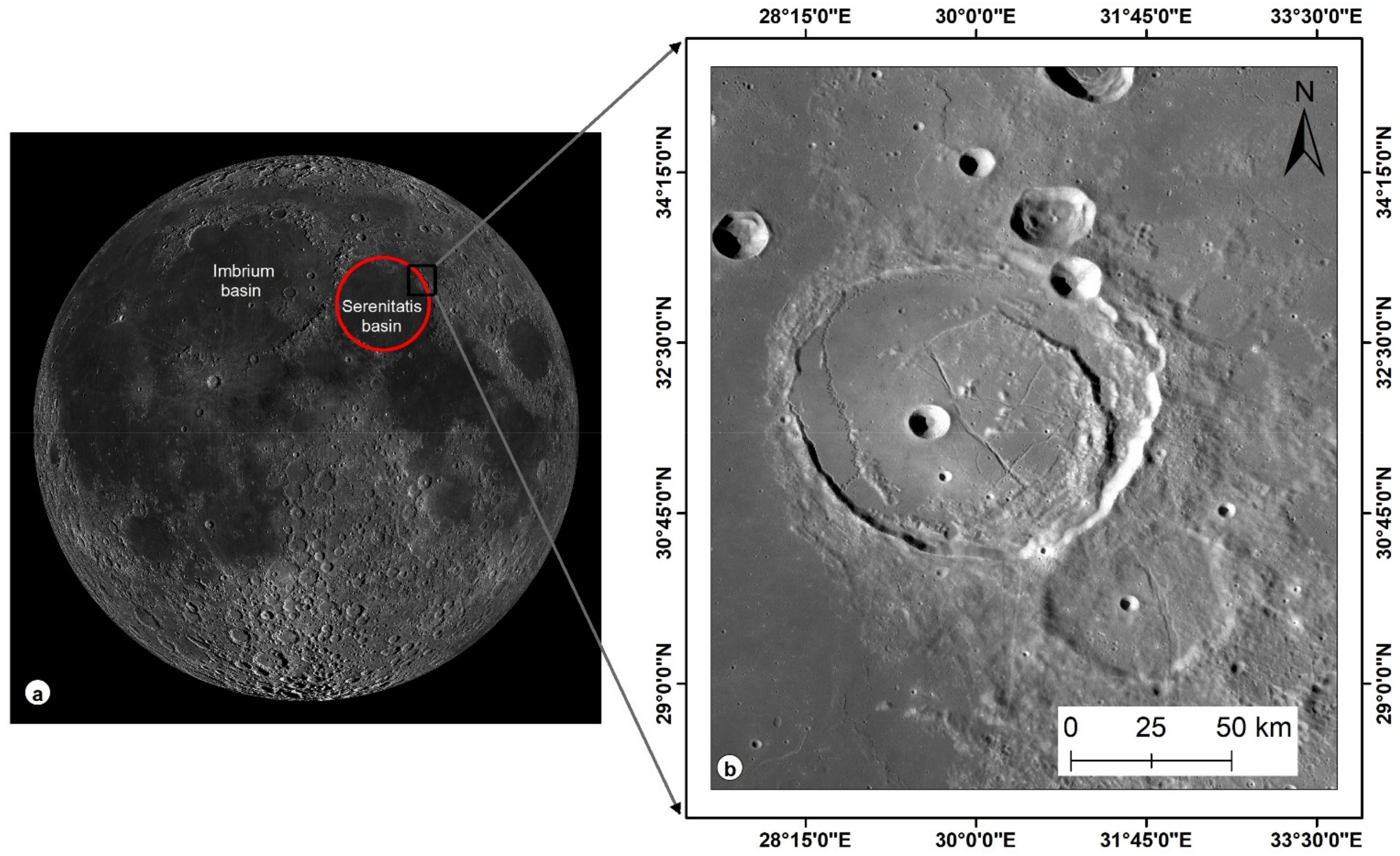
2. Study Area
3. Data Collection and Processing Methodology
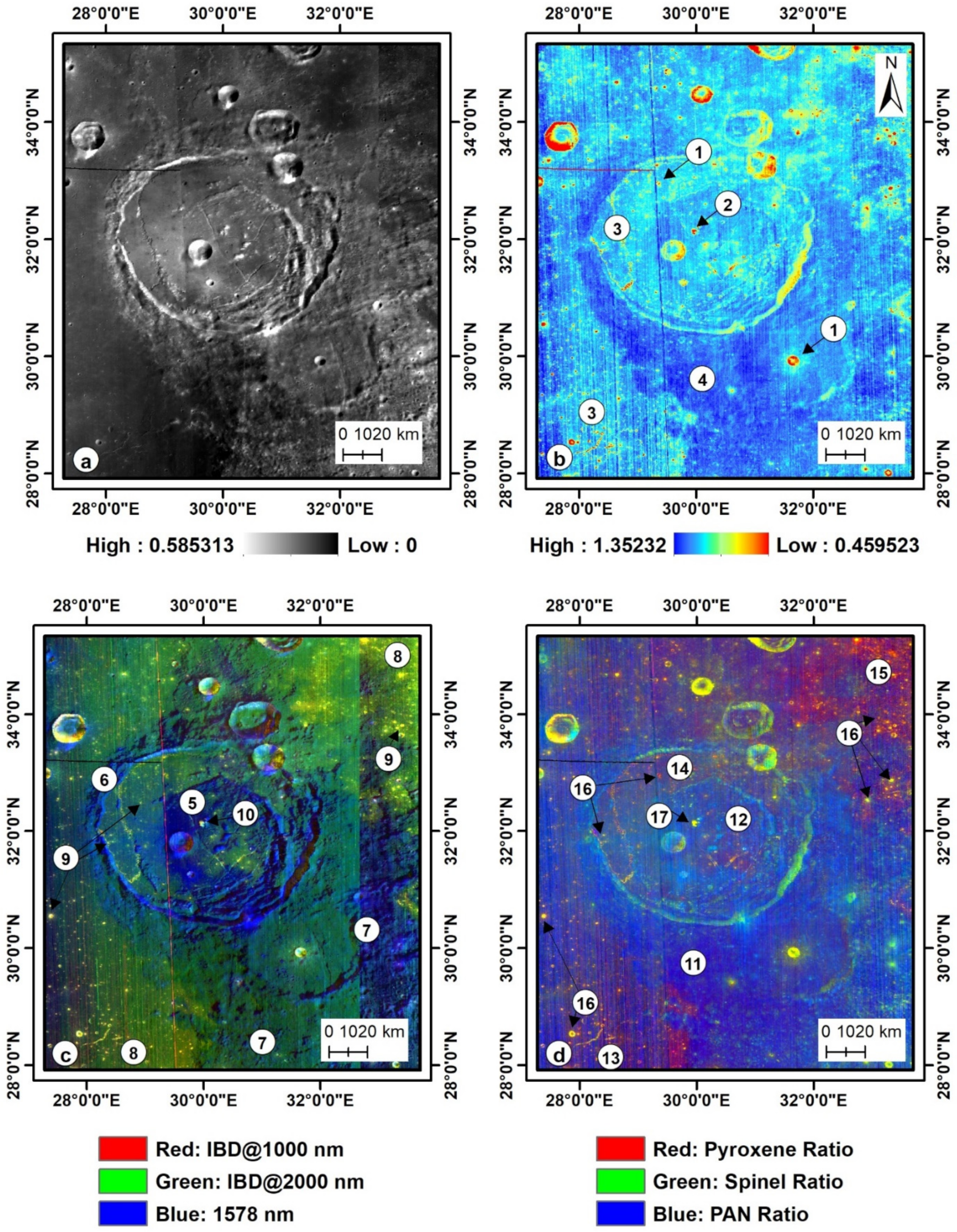
3.1. Integrated Band Depth (IBD) Analysis-Based Color Composite
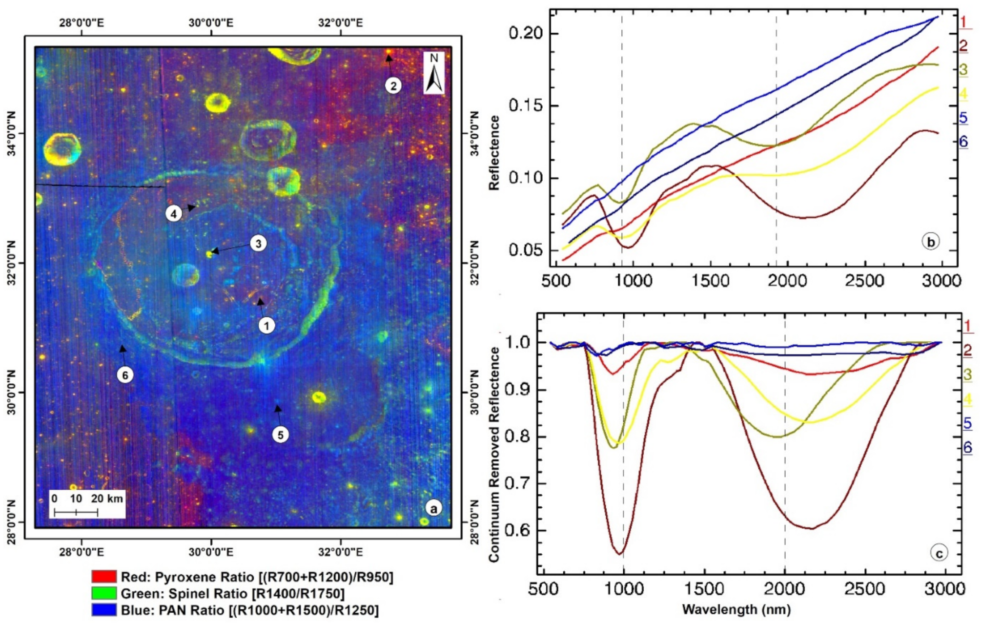
3.2. Rock Type Color Composite
4. Results and Discussion
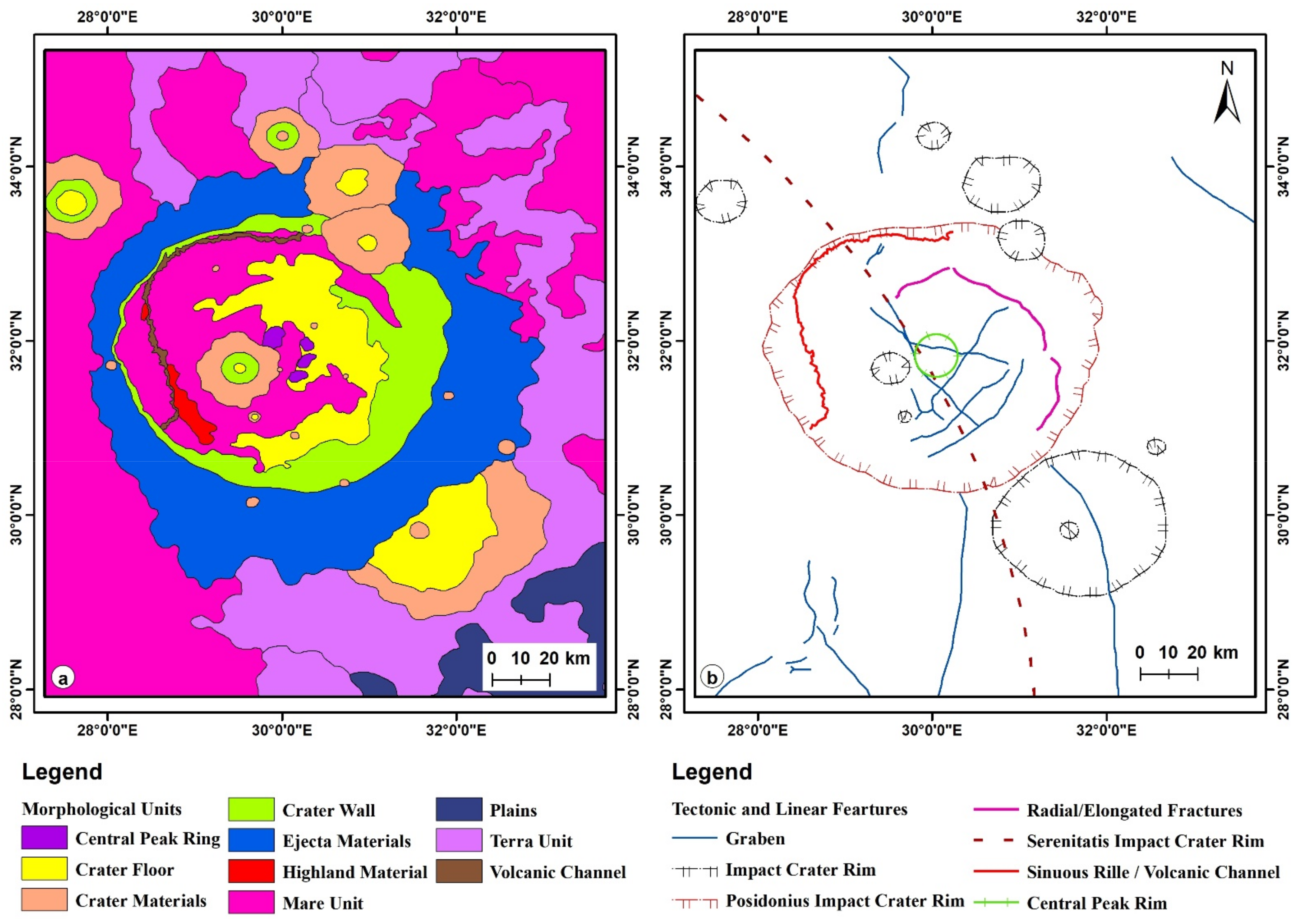
4.1. Morphological Mapping and Tectonics of Posidonius Crater
4.1.1. Morphology of Posidonius Crater
Central Peak Ring and Crater Floor
Crater Moat and Other Mare Units
Crater Wall and Ejecta Blanket
Highland and Its Related Materials
4.1.2. Tectonics of Posidonius Crater
Radial/Elongated Fractures
Grabens
Posidonius, Serenitatis and Other Impact Crater Rims
Central Peak Ring and Sinuous Rille/Volcanic Channel
4.2. Chronology and Stratigraphy of Posidonius Crater Region
4.3. Mineralogical Diversity Mapping and Reflectance Spectra Analysis of Posidonius Crater
5. Conclusions
- ✓
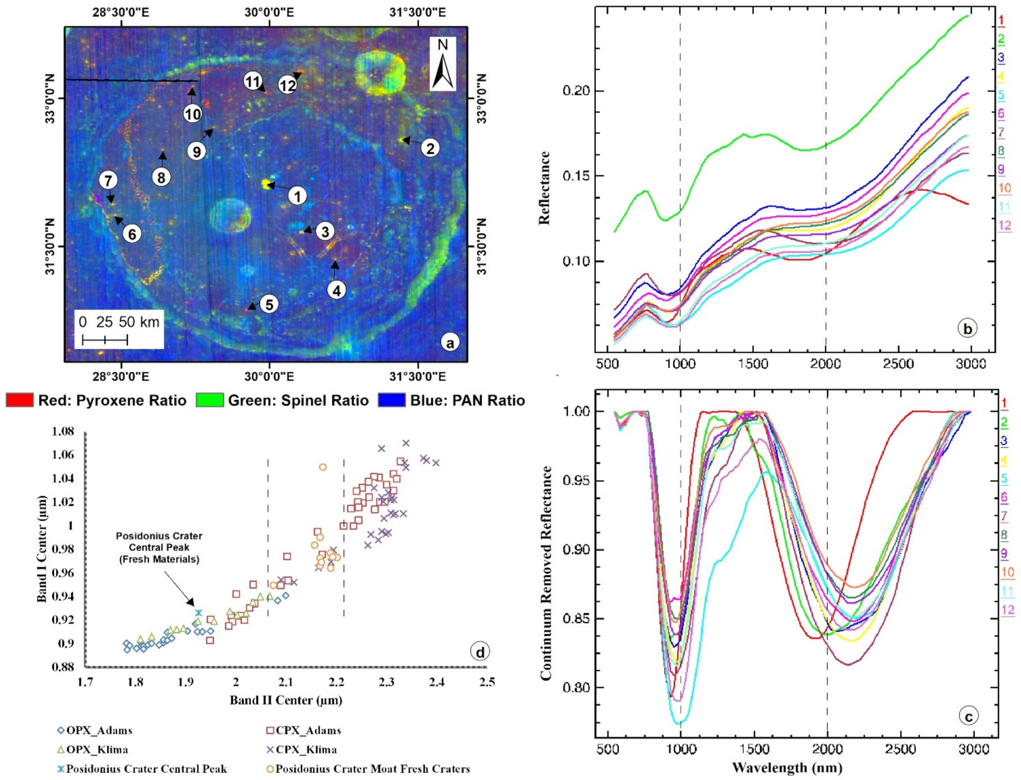
- The RGB color composite images derived using integrated band depth (IBD) and rock type analyses support the delineation of mineralogical units and lithological diversity of the studied region. In this regard, it is observed that one of the four central peak ring massifs contains noritic-rich low-calcium pyroxene (mafic pluton). The analysis of reflectance spectra band parameters of fresh craters in the mare units indicates the composition of the clinopyroxene (pigeonite). Moreover, the collected reflectance spectra and their band parameters of fresh crater units and mare units were validated and compared with existing RELAB data.
- ✓
- Morphological characteristics highlight the various surface components, such as highland material, terra units, plains, mare units, volcanic channels, crater materials, the central peak ring, the crater floor and the crater wall.
- ✓
- Mapping of linear and tectonic characterization has been obtained to ascertain the surficial process of the crater with different units, such as grabens, radial/elongated fractures, volcanic channels/sinuous rilles and impact-related circular features, and the respective unit ranges were observed.
- ✓
- The crater size frequency distribution (CSFD)-based age dating shows the Posidonius crater is 3.72 Ga old and belongs to upper Imbrian period. The moat mare units show ages of 3.5 and 3.34 Ga.
- ✓
- From the overall observations, it is observed that the Posidonius floor-fractured complex crater (diameter of 112km) comes under the type-III FFC, which is vested with a central peak ring and moat. Moreover, the mineralogically evident intrusion of a sill and dike favors the conditions for the fracture system. Eventually, it is shown that the origin and evolution of the crater occurred due to stress and strain, which were generated due to adjacent intrusive mafic plutonic lithospheric loading from the Serenitatis basin’s formation.
Author Contributions
Funding
Data Availability Statement
Acknowledgments
Conflicts of Interest
References
- Beals, C.S.; Halliday, I. Impact craters of the Earth and Moon. J. R. Astron Soc. Can. 1965, 59, 199. [Google Scholar]
- Melosh, H.J.; Ivanov, B.A. Impact crater collapse. Annu. Rev. Earth Plan. Sci. 1999, 27, 385–415. [Google Scholar] [CrossRef] [Green Version]
- Robbins, S.J.; Watters, W.A.; Chappelow, J.E.; Bray, V.J.; Daubar, I.J.; Craddock, R.A.; Beyer, R.A.; Landis, M.; Ostrach, L.R.; Tornabene, L.; et al. Measuring impact crater depth throughout the solar system. Meteorit. Planet. Sci. 2018, 53, 583–637. [Google Scholar] [CrossRef]
- Hiesinger, H.; Head, J.W., III. New views of lunar geoscience: An introduction and overview. Rev. Miner. Geochem. 2006, 60, 1–81. [Google Scholar] [CrossRef]
- Hiesinger, H.; Jaumann, R. Chapter 23—The Moon. In Encyclopedia of the Solar System, 3rd ed.; Elsevier BV: Amsterdam, The Netherlands, 2014; pp. 493–538. [Google Scholar] [CrossRef]
- Harris, A.W.; Drube, L.; McFadden, L.A.; Binzel, R.P. Near-Earth Objects. In Encyclopedia of the Solar System, 3rd ed.; Elsevier BV: Amsterdam, The Netherlands, 2014; pp. 603–623. [Google Scholar] [CrossRef]
- Schultz, P.H. Floor-fractured lunar craters. Earth Moon Planets 1976, 15, 241–273. [Google Scholar] [CrossRef]
- Jozwiak, L.M.; Head, J.W.; Zuber, M.T.; Smith, D.E.; Neumann, G.A. Lunar floor-fractured craters: Classification, distribution, origin and implications for magmatism and shallow crustal structure. J. Geophys. Res. Planets 2012, 117, 1–23. [Google Scholar] [CrossRef]
- Masursky, H. A preliminary report on the role of isostatic rebound in the geologic development of the lunar crater Ptolemaeus. Astrogeol. Stud. Annu. Prog. Rep. 1964, 1, 102–134. [Google Scholar]
- Daneš, Z.F. Rebound processes in large craters. Astrogeol. Stud. Annu. Prog. Rep. 1965, 81–100. [Google Scholar]
- Brennan, W.J. Modification of premare impact craters by volcanism and tectonism. Earth Moon Planets 1975, 12, 449–461. [Google Scholar] [CrossRef]
- Cathles, L.M. Viscosity of the Earth’s Mantle; Princeton University Press: Princeton, NJ, USA, 2015. [Google Scholar]
- Hall, J.L.; Solomon, S.C.; Head, J.W. Lunar floor-fractured craters: Evidence for viscous relaxation of crater topography. J. Geophys. Res. Solid Earth 1981, 86, 9537–9552. [Google Scholar] [CrossRef] [Green Version]
- Wichman, R.W.; Schultz, P.H. Floor-fractured craters in Mare Smythii and west of Oceanus Procellarum: Implications of crater modification by viscous relaxation and igneous intrusion models. J. Geophys. Res. Planets 1995, 100, 21201–21218. [Google Scholar] [CrossRef]
- Dombard, A.J.; Gillis, J. Testing the viability of topographic relaxation as a mechanism of the formation of lunar floor-fractured craters. J. Geophys. Res. 2001, 106, 901–927. [Google Scholar] [CrossRef]
- Thorey, C.; Michaut, C. A model for the dynamics of crater-centered intrusion: Application to lunar floor-fractured craters. J. Geophys. Res. Planets 2014, 119, 286–312. [Google Scholar] [CrossRef]
- Wilson, L.; Head, J.W. Controls on lunar basaltic volcanic eruption structure and morphology: Gas release patterns in sequential eruption phases. Geophys. Res. Lett. 2018, 45, 5852–5859. [Google Scholar] [CrossRef] [Green Version]
- Bennett, K.A.; Horgan, B.H.; Gaddis, L.R.; Greenhagen, B.T.; Allen, C.C.; Hayne, P.O.; Bell, J.F., III; Paige, D.A. Complex explosive volcanic activity on the Moon within Oppenheimer crater. Icarus 2016, 273, 296–314. [Google Scholar] [CrossRef]
- Pathak, S.; Dagar, A.K.; Bhattacharya, S.; Moitra, H.; Chauhan, M.; Gupta, S. Geological insights into lunar floor-fractured crater Atlas. Icarus 2021, 360, 114374. [Google Scholar] [CrossRef]
- Purohit, A.N.; Patel, S.M.; Thaker, A.D.; Solanki, P.M. Compositional and morphological analysis of Gassendi crater. J. Earth Syst. Sci. 2021, 130, 1–23. [Google Scholar] [CrossRef]
- Giguere, T.A.; Hawke, B.R.; Gillis-Davis, J.J.; Lemelin, M.; Boyce, J.M.; Trang, D.; Lawrence, S.J.; Stopar, J.D.; Campbell, B.A.; Gaddis, L.R.; et al. Volcanic Processes in the Gassendi Region of the Moon. J. Geophys. Res. Planets 2020, 125, e2019JE006034. [Google Scholar] [CrossRef]
- Souchon, A.L.; Besse, S.; Pinet, P.C.; Chevrel, S.D.; Daydou, Y.H.; Josset, J.L.; D’Uston, L.; Haruyama, J. Local spectrophotometric properties of pyroclastic deposits at the Lavoisier lunar crater. Icarus 2013, 225, 1–4. [Google Scholar] [CrossRef]
- Papike, J.J. Comparative planetary mineralogy; chemistry of melt-derived pyroxene, feldspar, and olivine. Rev. Mineral. Geochem. 1998, 36, 7-01–7-12. [Google Scholar]
- Shearer, C.K.; Hess, P.C.; Wieczorek, M.A.; Pritchard, M.E.; Parmentier, E.M.; Borg, L.E.; Longhi, J.; Elkins-Tanton, L.T.; Neal, C.R.; Antonenko, I.; et al. Thermal and magmatic evolution of the Moon. Rev. Mineral. Geochem. 2006, 60, 365–518. [Google Scholar] [CrossRef]
- Pieters, C.M.; Boardman, J.; Buratti, B.; Chatterjee, A.; Clark, R.; Glavich, T.; Green, R.; Head, J., III; Isaacson, P.; Malaret, E.; et al. The Moon mineralogy mapper (M3) on chandrayaan-1. Curr. Sci. 2009, 96, 500–505. [Google Scholar]
- Green, R.O.; Pieters, C.; Mouroulis, P.; Eastwood, M.; Boardman, J.; Glavich, T.; Isaacson, P.; Annadurai, M.; Besse, S.; Barr, D.; et al. The Moon Mineralogy Mapper (M3) imaging spectrometer for lunar science: Instrument description, calibration, on-orbit measurements, science data calibration and on-orbit validation. J. Geophys. Res. Planets 2011, 116, 1–31. [Google Scholar] [CrossRef] [Green Version]
- Staid, M.I.; Pieters, C.M.; Besse, S.; Boardman, J.; Dhingra, D.; Green, R.; Head, J.W.; Isaacson, P.; Klima, R.; Kramer, G.; et al. The mineralogy of late stage lunar volcanism as observed by the Moon Mineralogy Mapper on Chandrayaan-1. J. Geophys. Res. Planets 2011, 116, 1–15. [Google Scholar] [CrossRef]
- Klima, R.L.; Dyar, M.D.; Pieters, C.M. Near-infrared spectra of clinopyroxenes: Effects of calcium content and crystal structure. Meteorit. Planet. Sci. 2011, 46, 379–395. [Google Scholar] [CrossRef]
- Isaacson, P.J.; Pieters, C.M.; Besse, S.; Clark, R.N.; Head, J.W.; Klima, R.L.; Mustard, J.F.; Petro, N.E.; Staid, M.I.; Sunshine, J.M.; et al. Remote compositional analysis of lunar olivine-rich lithologies with Moon Mineralogy Mapper (M3) spectra. J. Geophys. Res. Planets 2011, 116. [Google Scholar] [CrossRef] [Green Version]
- Sunshine, J.M.; Pieters, C.M.; Pratt, S.F. Deconvolution of mineral absorption bands: An improved approach. J. Geophys. Res. Solid Earth 1990, 95, 6955–6966. [Google Scholar] [CrossRef] [Green Version]
- Clark, R.N.; Rencz, A.N. Spectroscopy of rocks and minerals, and principles of spectroscopy. Man. Remote Sens. 1999, 3, 3–58. [Google Scholar]
- Cheek, L.C.; Pieters, C.M. Reflectance spectroscopy of plagioclase-dominated mineral mixtures: Implications for characterizing lunar anorthosites remotely. Am. Mineral. 2014, 99, 1871–1892. [Google Scholar] [CrossRef]
- Von Engelhardt, W.; Stöffler, D. Stages of shock metamorphism in crystalline rocks of the Ries Basin, Germany. In Shock Metamorphism of Natural Materials; French, N.M., Short, N.M., Eds.; Mono Book Corporation: Baltimore, MD, USA, 1968; pp. 159–168. [Google Scholar]
- Stöffler, D. Progressive metamorphism and classification of shocked and brecciated crystalline rocks at impact craters. J. Geophys. Res. 1971, 76, 5541–5551. [Google Scholar] [CrossRef]
- Bruckenthal, E.A.; Pieters, C.M. Spectral effects of natural shock on plagioclase feldspar. In Proceedings of the 15th Lunar and Planetary Science Conference, Houston, TX, USA, 12–16 March 1984; pp. 96–97. [Google Scholar]
- Adams, J.B.; Horz, F.; Gibbons, R.V. Effects of shock-loading on the reflectance spectra of plagioclase, pyroxene, and glass. In Proceedings of the 10th Lunar and Planetary Science Conference, Houston, TX, USA, 19–23 March 1979; pp. 1–3. [Google Scholar]
- Adams, J.B. Visible and near-infrared diffuse reflectance spectra of pyroxenes as applied to remote sensing of solid objects in the solar system. J. Geophys. Res. 1974, 79, 4829–4836. [Google Scholar] [CrossRef]
- Burns, R.G.; Burns, R.G. Mineralogical Applications of Crystal Field Theory; Cambridge University Press: Cambridge, UK, 1993. [Google Scholar]
- Staudacher, T.; Dominik, B.; Jessberger, E.K.; Kirsten, T. Consortium Breccia 73255: 40AR-39AR Dating. In Proceedings of the 9th Lunar and Planetary Science Conference, Houston, TX, USA, 13–17 March 1978; pp. 1098–1100. [Google Scholar]
- Solomon, S.C.; Head, J.W. Lunar mascon basins: Lava filling, tectonics, and evolution of the lithosphere. Rev. Geophys. 1980, 18, 107–141. [Google Scholar] [CrossRef]
- Phillips, R.J.; Conel, J.E.; Abbott, E.A.; Sjogren, W.L.; Morton, J.B. Mascons: Progress toward a unique solution for mass distribution. J. Geophys. Res. 1972, 77, 7106–7114. [Google Scholar] [CrossRef]
- Howard, K.A.; Wilhelms, D.E.; Scott, D.H. Lunar basin formation and highland stratigraphy. Rev. Geophys. 1974, 12, 309–327. [Google Scholar] [CrossRef]
- Kaur, P.; Bhattacharya, S.; Chauhan, P.; Kumar, A.K. Mineralogy of Mare Serenitatis on the near side of the Moon based on Chandrayaan-1 Moon Mineralogy Mapper (M3) observations. Icarus 2013, 222, 137–148. [Google Scholar] [CrossRef]
- Robinson, M.S.; Brylow, S.M.; Tschimmel, M.; Humm, D.; Lawrence, S.J.; Thomas, P.C.; Denevi, B.W.; Bowman-Cisneros, E.; Zerr, J.; Ravine, M.A.; et al. Lunar reconnaissance orbiter camera (LROC) instrument overview. Space Sci. Rev. 2010, 150, 81–124. [Google Scholar] [CrossRef]
- Smith, D.E.; Zuber, M.T.; Neumann, G.A.; Lemoine, F.G.; Mazarico, E.; Torrence, M.H.; McGarry, J.F.; Rowlands, D.D.; Head, J.W.; Duxbury, T.H.; et al. Initial observations from the lunar orbiter laser altimeter (LOLA). Geophys. Res. Lett. 2010, 37, 18. [Google Scholar] [CrossRef]
- Barker, M.K.; Mazarico, E.; Neumann, G.A.; Zuber, M.T.; Haruyama, J.; Smith, D.E. A new lunar digital elevation model from the Lunar Orbiter Laser Altimeter and SELENE Terrain Camera. Icarus 2016, 273, 346–355. [Google Scholar] [CrossRef] [Green Version]
- Besse, S.; Sunshine, J.; Staid, M.; Boardman, J.; Pieters, C.; Guasqui, P.; Malaret, E.; McLaughlin, S.; Yokota, Y.; Li, J.Y. A visible and near-infrared photometric correction for Moon Mineralogy Mapper (M3). Icarus 2013, 222, 229–242. [Google Scholar] [CrossRef]
- Besse, S.; Yokota, Y.; Boardman, J.; Green, R.; Haruyama, J.; Isaacson, P.; Mall, U.; Matsunaga, T.; Ohtake, M.; Pieters, C.; et al. One Moon, many measurements 2: Photometric corrections. Icarus 2013, 226, 127–139. [Google Scholar] [CrossRef]
- Fortezzo, C.M.; Spudis, P.D.; Harrel, S.L. Release of the Digital Unified Global Geologic Map of the Moon At 1:5,000,000-Scale. In Proceedings of the 51st Lunar and Planetary Science Conference, Houston, TX, USA, 16–20 March 2020. [Google Scholar]
- Pinto, L.; Fortunato, A.B.; Freire, P. Sensitivity analysis of non-cohesive sediment transport formulae. Cont. Shelf Res. 2006, 26, 1826–1839. [Google Scholar] [CrossRef]
- Denghua, Z.; Jie, L.; Mingchao, L. An approach to 3D NURBS modelling of complex fault network considering its historic tectonics. Prog. Nat. Sci. 2006, 16, 546–553. [Google Scholar] [CrossRef]
- Pinto, V.; Font, X.; Salgot, M.; Tapias, J.C.; Mana, T. Using 3-D structures and their virtual representation as a tool for restoring opencast mines and quarries. Eng. Geol. 2002, 63, 121–129. [Google Scholar] [CrossRef]
- Lemon, A.M.; Jones, N.L. Building solid models from boreholes and user-defined cross-sections. Comput. Geosci. 2003, 29, 547–555. [Google Scholar] [CrossRef]
- Turner, A.K. Applications of three-dimensional geoscientific mapping and modeling systems to hydrogeological studies. In Three-Dimensional Modeling with Geoscientific Information Systems; Springer: Dordrecht, The Netherlands, 1992; pp. 327–364. [Google Scholar] [CrossRef]
- Apel, M. From 3d geomodelling systems towards 3d geoscience information systems: Data model, query functionality, and data management. Comput. Geosci. 2006, 32, 222–229. [Google Scholar] [CrossRef]
- Baojun, W.; Bin, S.; Zhen, S. A simple approach to 3D geological modelling and visualization. Bull. Eng. Geol. Environ. 2009, 68, 559–565. [Google Scholar] [CrossRef]
- Wilhelms, D.E.; Byrne, C.J. Stratigraphy of Lunar Craters. Available online: http://www.imageagain.com/Strata/StratigraphyCraters (accessed on 15 October 2021).
- Crater Analysis Techniques Working Group. Standard techniques for presentation and analysis of crater size-frequency data. Icarus 1979, 37, 467–474. [Google Scholar] [CrossRef] [Green Version]
- Neukum, G.; Ivanov, B.A. Crater size distributions and impact probabilities on Earth from Lunar, terrestrial-planet, and asteroid cratering data. In Hazards Due to Comets and Asteroids; Gehrels, T., Ed.; University of Arizona Press: Tucson, AZ, USA, 1994; pp. 359–416. [Google Scholar]
- Neukum, G.; Ivanov, B.A.; Hartmann, W.K. Cratering Records in the Inner Solar System in Relation to the Lunar Reference System, Chronology and Evolution of Mars. In Space Sciences Series of ISSI; Kallenbach, R., Geiss, J., Hartmann, W.K., Eds.; Springer: Dordrecht, The Netherlands, 2001; pp. 55–86. [Google Scholar] [CrossRef]
- Kneissl, T.; van Gasselt, S.; Neukum, G. Map-projection-independent crater size-frequency determination in GIS environments—New software tool for ArcGIS. Planet. Space Sci. 2011, 59, 1243–1254. [Google Scholar] [CrossRef]
- Mustard, J.F.; Pieters, C.M.; Isaacson, P.J.; Head, J.W.; Besse, S.; Clark, R.N.; Klima, R.L.; Petro, N.E.; Staid, M.I.; Sunshine, J.M.; et al. Compositional diversity and geologic insights of the Aristarchus crater from Moon Mineralogy Mapper data. J. Geophys. Res. Planets 2011, 116, 1–17. [Google Scholar] [CrossRef] [Green Version]
- Cheek, L.C.; Pieters, C.M.; Boardman, J.W.; Clark, R.N.; Combe, J.P.; Head, J.W.; Isaacson, P.J.; McCord, T.B.; Moriarty, D.; Nettles, J.W.; et al. Goldschmidt crater and the Moon’s north polar region: Results from the Moon Mineralogy Mapper (M3). J. Geophys. Res. Planets 2011, 116. [Google Scholar] [CrossRef] [Green Version]
- Varatharajan, I.; Srivastava, N.; Murty, S.V. Mineralogy of young lunar mare basalts: Assessment of temporal and spatial heterogeneity using M3 data from Chandrayaan-1. Icarus 2014, 236, 56–71. [Google Scholar] [CrossRef]
- Kumaresan, P.R.; Saravanavel, J.; Palanivel, K. Lithological mapping of Eratosthenes crater region using Moon Mineralogy Mapper of Chandrayaan-1. Planet. Space Sci. 2020, 182, 104817. [Google Scholar] [CrossRef]
- Arivazhagan, S.; Karthi, A. Compositional and chronological characterization of mare crisium using Chandrayaan-1 and LROC-WAC data. Planet. Space Sci. 2018, 161, 41–56. [Google Scholar] [CrossRef]
- Karthi, A.; Arivazhagan, S. Chronological and compositional mapping of the Mare Orientale basin using Chandrayaan-1–M3 and LRO datasets. Icarus 2021, 10, 114844. [Google Scholar] [CrossRef]
- Pieters, C.M.; Hanna, K.D.; Cheek, L.; Dhingra, D.; Prissel, T.; Jackson, C.; Moriarty, D.; Parman, S.; Taylor, L.A. The distribution of Mg-spinel across the Moon and constraints on crustal origin. Am. Mineral. 2014, 99, 1893–1910. [Google Scholar] [CrossRef]
- Chauhan, M.; Bhattacharya, S.; Pathak, S.; Chauhan, P. Remote spectral–compositional analysis of basalt mineralogy at Hansteen-Billy, Moon. Meteorit. Planet. Sci. 2018, 53, 2583–2595. [Google Scholar] [CrossRef]
- Thesniya, P.M.; Rajesh, V.J.; Flahaut, J. Ages and chemistry of mare basaltic units in the Grimaldi basin on the nearside of the Moon: Implications for the volcanic history of the basin. Meteorit. Planet. Sci. 2020, 55, 2375–2403. [Google Scholar] [CrossRef]
- Thesniya, P.M.; Rajesh, V.J. Pyroxene chemistry and crystallization history of basaltic units in the Mare Humorum on the nearside of the Moon: Implications for the volcanic history of the region. Planet. Space Sci. 2020, 193, 105093. [Google Scholar] [CrossRef]
- Bhatt, H.; Chauhan, P.; Solanki, P. Compositional mapping and the evolutionary history of Mare Tranquillitatis. J. Earth Syst. Sci. 2020, 129, 1–4. [Google Scholar] [CrossRef]
- Clark, R.N.; Roush, T.L. Reflectance spectroscopy: Quantitative analysis techniques for remote sensing applications. J. Geophys. Res. Solid Earth 1984, 89, 6329–6340. [Google Scholar] [CrossRef]
- Pieters, C.M.; Taylor, L.A.; Noble, S.K.; Keller, L.P.; Hapke, B.; Morris, R.V.; Allen, C.C.; McKAY, D.S.; Wentworth, S. Space weathering on airless bodies: Resolving a mystery with lunar samples. Meteorit. Planet. Sci. 2000, 35, 1101–1107. [Google Scholar] [CrossRef]
- Hapke, B. Space weathering from Mercury to the asteroid belt. J. Geophys. Res. Planets 2001, 106, 10039–10073. [Google Scholar] [CrossRef]
- Lucey, P.G.; Taylor, G.J.; Malaret, E. Abundance and distribution of iron on the Moon. Science 1995, 268, 1150–1153. [Google Scholar] [CrossRef] [PubMed]
- Wilcox, B.B.; Lucey, P.G.; Gillis, J.J. Mapping iron in the lunar mare: An improved approach. J. Geophys. Res. Planets 2005, 110. [Google Scholar] [CrossRef] [Green Version]
- Cloutis, E.A.; Gaffey, M.J. Pyroxene spectroscopy revisited: Spectral-compositional correlations and relationship to geothermometry. J. Geophys. Res. Planets 1991, 96, 22809–22826. [Google Scholar] [CrossRef]
- Cloutis, E.A.; Gaffey, M.J. Spectral-compositional variations in the constituent minerals of mafic and ultramafic assemblages and remote sensing implications. Earth Moon Planets 1991, 53, 11–53. [Google Scholar] [CrossRef]
- Klima, R.L.; Pieters, C.M.; Boardman, J.W.; Green, R.O.; Head, J.W.; Isaacson, P.J.; Mustard, J.F.; Nettles, J.W.; Petro, N.E.; Staid, M.I.; et al. New insights into lunar petrology: Distribution and composition of prominent low-Ca pyroxene exposures as observed by the Moon Mineralogy Mapper (M3). J. Geophys. Res. Planets 2011, 116. [Google Scholar] [CrossRef]
- Horgan, B.H.; Cloutis, E.A.; Mann, P.; Bell, J.F., III. Near-infrared spectra of ferrous mineral mixtures and methods for their identification in planetary surface spectra. Icarus 2014, 234, 132–154. [Google Scholar] [CrossRef] [Green Version]
- Milton, D.J.; Barlow, B.C.; Brett, R.; Brown, A.R.; Glikson, A.Y.; Manwaring, E.A.; Moss, F.J.; Sedmik, E.C.; van Son, J.; Young, G.A. Gosses bluff impact structure, Australia. Science 1972, 175, 1199–1207. [Google Scholar] [CrossRef]
- Alexopoulos, J.S.; McKinnon, W.B. Large Impact Craters and Basins on Venus, with Implications for Ring Mechanics on the Terrestrial Planets; Special Papers-Geological Society of America: Boulder, CO, USA, 1994; p. 29. [Google Scholar]
- Baker, D.M.; Head, J.W.; Fassett, C.I.; Kadish, S.J.; Smith, D.E.; Zuber, M.T.; Neumann, G.A. The transition from complex crater to peak-ring basin on the Moon: New observations from the Lunar Orbiter Laser Altimeter (LOLA) instrument. Icarus 2011, 214, 377–393. [Google Scholar] [CrossRef]
- McCauley, J.F.; Wilhelms, D.E. Geological provinces of the near side of the Moon. Icarus 1971, 15, 363–367. [Google Scholar] [CrossRef]
- Wilhelms, D.E.; McCauley, J.F. Geologic Map of the Near Side of the Moon; US Geological Survey: Washington DC, WA, USA, 1971. [Google Scholar]
- Wilhelms, D.E.; Oberbeck, V.R.; Aggarwal, H.R. Size-frequency distributions of primary and secondary lunar impact craters. In Proceedings of the 9th Lunar and Planetary Science Conference, Houston, TX, USA, 13–17 March 1978; pp. 3735–3762. [Google Scholar]
- Golombek, M.P. Structural analysis of lunar grabens and the shallow crustal structure of the Moon. J. Geophys. Res. Solid Earth 1979, 84, 4657–4666. [Google Scholar] [CrossRef]
- Watters, T.R.; Johnson, C.L.; Schultz, R.A. Lunar tectonics. Planet. Tecton. 2010, 11, 121–182. [Google Scholar]
- Klimczak, C. Geomorphology of lunar grabens requires igneous dikes at depth. Geology 2014, 42, 963–966. [Google Scholar] [CrossRef] [Green Version]
- Nahm, A. Spatial Distribution and Characteristics of Graben on the Lunar Nearside. In Proceedings of the EGU General Assembly Conference Abstracts, Vienna, Austria, 17–22 April 2016. [Google Scholar]
- Jozwiak, L.M.; Head, J.W.; Wilson, L. Lunar floor-fractured craters as magmatic intrusions: Geometry, modes of emplacement, associated tectonic and volcanic features, and implications for gravity anomalies. Icarus 2015, 248, 424–447. [Google Scholar] [CrossRef]
- Burg, J.P. 2014 Brittle Faulting. Available online: https://www.Bles.ethz.ch/structuralgeology/JPB/Bles/English/2faulting.pdf (accessed on 25 September 2021).
- Odling, N.E. Fluid Cow in fractured rocks at shallow levels in the Earth’s crust: An overview. In Deformation Enhanced Fluid Transport in the Earth’s Crust and Mantle; Holness, M.B., Ed.; Chapman and Hall: London, UK, 1997; pp. 289–314. [Google Scholar]
- Hargitai, H.; Byrne, P.K.; Korteniemi, J. Fracture. In Encyclopedia of Planetary Landforms; Hargitai, H., Kereszturi, A., Eds.; Springer: Berlin/Heidelberg, Germany, 2015; pp. 794–801. [Google Scholar]
- Morgan, J.; Bray, V.J. Peak-Ring Structure. In Encyclopedia of Planetary Landforms; Springer: Berlin/Heidelberg, Germany, 2014; pp. 1–8. [Google Scholar] [CrossRef]
- Baldwin, R.B. On the tsunami theory of the origin of multi-ring basins. In Multi-Ring Basins: Formation and Evolution; Pergamon Press: New York, NY, USA, 1981; pp. 275–288. [Google Scholar]
- Melosh, H.J. A schematic model of crater modification by gravity. J. Geophys. Res. Solid Earth 1982, 87, 371–380. [Google Scholar] [CrossRef]
- Morgan, J.V.; Warner, M.R.; Collins, G.S.; Grieve, R.A.; Christeson, G.L.; Gulick, S.P.; Barton, P.J. Full waveform tomographic images of the peak ring at the Chicxulub impact crater. J. Geophys. Res. Solid Earth 2011, 116, 1–16. [Google Scholar] [CrossRef] [Green Version]
- Hurwitz, D.M.; Head, J.W.; Hiesinger, H. Lunar sinuous rilles: Distribution, characteristics, and implications for their origin. Planet. Space Sci. 2013, 79, 1–38. [Google Scholar] [CrossRef]
- Spudis, P.D.; Swann, G.A.; Greeley, R. The formation of Hadley Rille and implications for the geology of the Apollo 15 region. In Proceedings of the 19th Lunar and Planetary Science Conference, Houston TX, USA, 14–18 March 1988; pp. 243–254. [Google Scholar]
- Head, J.W.; Wilson, L. Lunar sinuous rille formation by thermal erosion: Conditions, rates and durations. In Proceedings of the 12th Lunar and Planetary Science Conference, Houston, TX, USA, 16–20 March 1981; pp. 427–429. [Google Scholar]
- Hurwitz, D.M.; Head, J.W.; Wilson, L.; Hiesinger, H. Origin of lunar sinuous rilles: Modeling effects of gravity, surface slope, and lava composition on erosion rates during the formation of Rima Prinz. J. Geophys. Res. Planets 2012, 117, E00H14. [Google Scholar] [CrossRef] [Green Version]
- Losiak, A.; Wilhelms, D.E.; Byrne, C.J.; Thaisen, K.G.; Weider, S.Z.; Kohout, T.; O’Sullivan, K.; Kring, D.A. A new lunar impact crater database. In Proceedings of the 40th Lunar and Planetary Science Conference, Houston, TX, USA, 23–27 March 2009; p. 1532. [Google Scholar]
- Losiak, A. A new lunar impact crater database (updated). In Proceedings of the 46th Lunar and Planetary Science Conference, Houston, TX, USA, 16–20 March 2015. [Google Scholar]
- Lucchitta, B.K.; Watkins, J.A. Age of graben systems on the Moon. In Proceedings of the 9th Lunar and Planetary Science Conference, Houston, TX, USA, 13–17 March 1978; pp. 3459–3472. [Google Scholar]
- Watters, T.R.; Robinson, M.S.; Banks, M.E.; Tran, T.; Denevi, B.W. Recent extensional tectonics on the Moon revealed by the Lunar Reconnaissance Orbiter Camera. Nat. Geosci. 2012, 5, 181–185. [Google Scholar] [CrossRef]
- Trask, N.J. Geologic comparison of mare materials in the lunar equatorial belt, including Apollo 11 and Apollo 12 landing sites. US Geol. Surv. Prof. Pap. 1971, 750D, 138–148. [Google Scholar]
- French, R.A.; Bina, C.R.; Robinson, M.S.; Watters, T.R. Small-scale lunar graben: Distribution, dimensions, and formation processes. Icarus 2015, 252, 95–106. [Google Scholar] [CrossRef]
- Pieters, C.M.; Hiroi, T. RELAB (Reflectance Experiment Laboratory): A NASA multiuser spectroscopy facility. In Proceedings of the 35th Lunar and Planetary Science Conference, Houston, TX, USA, 15–19 March 2004; p. 1720. Available online: https://www.planetary.brown.edu/relab. (accessed on 23 October 2021).
- Gaffey, M.J.; Cloutis, E.A.; Kelley, M.S.; Reed, K.L. Mineralogy of asteroids. In Asteroids III; Bottke, W.F., Cellino, A., Paolicchi, P., Binzel, R.P., Eds.; University of Arizona Press: Tucson, AR, USA, 2002; pp. 183–204. [Google Scholar]
- Horgan, B.; Bell, J.F., III. Widespread weathered glass on the surface of Mars. Geology 2012, 40, 391–394. [Google Scholar] [CrossRef]
- Xiao, L.; Head, J.W. Geological Characteristics of the Moon. In Oxford Research Encyclopedia of Planetary Science; Oxford University Press: Oxford, UK, 2020. [Google Scholar] [CrossRef]
- Pieters, C.M. Bullialdus: Strengthening the case for lunar plutons. Geophys. Res. Lett. 1991, 18, 2129–2132. [Google Scholar] [CrossRef] [Green Version]
- Tompkins, S.; Pieters, C.M. Mineralogy of the lunar crust: Results from Clementine. Meteorit. Planet. Sci. 1999, 34, 25–41. [Google Scholar] [CrossRef]


| S. No. | Name (Code) | Band Parameters | ||||||
|---|---|---|---|---|---|---|---|---|
| 1000 nm | 2000 nm | Band Area Ratio | ||||||
| Band Center | Band Depth | Band Area | Band Center | Band Depth | Band Area | |||
| 1 | PRS1 | 926.33 | 0.21 | 40.56 | 1925.67 | 0.16 | 98.50 | 2.42 |
| 2 | PRS2 | 949.65 | 0.17 | 44.41 | 2074.67 | 0.16 | 130.77 | 2.94 |
| 3 | PRS3 | 966.29 | 0.17 | 48.95 | 2167.73 | 0.16 | 128.90 | 2.63 |
| 4 | PRS4 | 972.61 | 0.18 | 48.97 | 2167.46 | 0.17 | 130.71 | 2.67 |
| 5 | PRS5 | 1049.85 | 0.20 | 99.48 | 2173.07 | 0.15 | 118.79 | 1.19 |
| 6 | PRS6 | 969.29 | 0.14 | 38.2 | 2170.36 | 0.15 | 119.83 | 3.13 |
| 7 | PRS7 | 983.65 | 0.18 | 61.10 | 2156.68 | 0.19 | 145.36 | 2.38 |
| 8 | PRS8 | 976.85 | 0.15 | 39.15 | 2188.29 | 0.13 | 103.53 | 2.64 |
| 9 | PRS9 | 973.19 | 0.16 | 44.17 | 2201.25 | 0.14 | 105.85 | 2.39 |
| 10 | PRS10 | 964.26 | 0.15 | 39.35 | 2188.65 | 0.13 | 94.57 | 2.40 |
| 11 | PRS11 | 973.70 | 0.18 | 52.55 | 2192.59 | 0.15 | 115.38 | 2.19 |
| 12 | PRS12 | 990.26 | 0.20 | 66.17 | 2167.46 | 0.17 | 130.71 | 1.97 |
Publisher’s Note: MDPI stays neutral with regard to jurisdictional claims in published maps and institutional affiliations. |
© 2022 by the authors. Licensee MDPI, Basel, Switzerland. This article is an open access article distributed under the terms and conditions of the Creative Commons Attribution (CC BY) license (https://creativecommons.org/licenses/by/4.0/).
Share and Cite
Salem, I.B.; Sharma, M.; Kumaresan, P.R.; Karthi, A.; Howari, F.M.; Nazzal, Y.; Xavier, C.M. An Investigation on the Morphological and Mineralogical Characteristics of Posidonius Floor Fractured Lunar Impact Crater Using Lunar Remote Sensing Data. Remote Sens. 2022, 14, 814. https://doi.org/10.3390/rs14040814
Salem IB, Sharma M, Kumaresan PR, Karthi A, Howari FM, Nazzal Y, Xavier CM. An Investigation on the Morphological and Mineralogical Characteristics of Posidonius Floor Fractured Lunar Impact Crater Using Lunar Remote Sensing Data. Remote Sensing. 2022; 14(4):814. https://doi.org/10.3390/rs14040814
Chicago/Turabian StyleSalem, Imen Ben, Manish Sharma, P. R. Kumaresan, A. Karthi, Fares M. Howari, Yousef Nazzal, and Cijo M. Xavier. 2022. "An Investigation on the Morphological and Mineralogical Characteristics of Posidonius Floor Fractured Lunar Impact Crater Using Lunar Remote Sensing Data" Remote Sensing 14, no. 4: 814. https://doi.org/10.3390/rs14040814
APA StyleSalem, I. B., Sharma, M., Kumaresan, P. R., Karthi, A., Howari, F. M., Nazzal, Y., & Xavier, C. M. (2022). An Investigation on the Morphological and Mineralogical Characteristics of Posidonius Floor Fractured Lunar Impact Crater Using Lunar Remote Sensing Data. Remote Sensing, 14(4), 814. https://doi.org/10.3390/rs14040814