Abstract
Conventional bathymetric inversion approaches require bathymetric data as ground truth to obtain shallow water depth from high spatial resolution remote sensing imagery. Thus, bathymetric mapping methods that do not require inputs from in situ measurements are highly desirable. In this paper, we propose a dual-band model improvement method and evaluate the performance of this novel dual-band model approach to obtain the underwater terrain around a coastal island by using four WorldView-2/3 imageries. Then, we validate the results through changing water column properties with the Kd multiple linear regression model simulated by Hydrolight. We multiply the best coefficient and blue–green band value with different substrates on the pixels, which sample along the coastal line and isobath. The results show that the mean bias of inversed depth ranges from 1.73 to 2.96 m in the four imageries. The overall accuracy of root mean square errors (RMSEs) is better for depths shallower than 10 m, and the average relative error is 11.89%. The inversion accuracy of this new model is higher than Lee’s classical Kd model and has a wider range of applications than Chen’s dual-band model. The no-ground-truth dual-band algorithm has higher accuracy than the other log-ratio methods mentioned in this paper.
1. Introduction
Shallow water depth measurements are crucial for coastal surveys and activities. Bathymetric data can be used to understand seafloor ecosystem distribution, to plan for protection and management of coastal environments, and to explore marine resources. Many methods are utilized in bathymetry, which do not involve remote sensing [1,2]. New technological breakthroughs on multibeam sonars particularly enhance efficiency and coverage on bathymetric data. Autonomous platforms will map the seabed depth on long-duration, ocean-wide transits to improve the efficiency of multibeam sonar [3].
The traditional and time-consuming water depth measurement is via a shipborne echo sounder, which has application limitations for hard-to-reach areas [4]. To overcome this, Chen et al. [5] proposed water depth inversion with remote sensing images to reduce the cost of field measurements. At present, the development of remote sensing has allowed for significant improvements in shallow water habitat and bathymetry mapping [6]. Satellite-derived bathymetry is becoming a cost-effective method that can be used to rapidly obtain large-scale and high-resolution bathymetric information [7,8].
Remote sensing methods for bathymetry inversion can be divided into two categories: (i) single-source and single-algorithm inversion approaches, and (ii) coupling inversion approaches [9]. The former uses an algorithm to estimate water depth from multispectral data, including spectral matching approaches based on the radiative transfer theory, linear wave approaches based on the linear wave theory, photogrammetric approaches based on through-water photogrammetry, and the advanced log-ratio method (LRM) based on the Lyzenga’s theory [9,10].
The multiple-band log-linear models are relatively simple techniques that give acceptable results in different situations. Lyzenga [11] proposed a theoretical model for determining bathymetry using passive remote sensing and successfully inverted bathymetry results. Philpot [12] evidenced the depth and the effective attenuation coefficient of water over several different bottom types to be retrieved from passive, multispectral imagery. Stumpf et al. [13] developed an empirical solution by using low-albedo reflectance. Fournier [14] established a seafloor hyperspectral reflectance model to simulate the spectral results of beach and chlorophyll absorption reflection, which was used to simulate the light absorption scattering results on the seafloor and to fit the intrinsic optical properties of the water column and the bottom spectral reflectance profile. Liu et al. [9] estimated water depth from Landsat-8 data to calibrate the empirical model for high spatial resolution and multi-time imagery.
Coupling inversion approaches include single-source and multisource coupling. The latter utilizes the water depth estimated by the ICESat-2 data to calibrate empirical models [15]. LiDAR considers the complexity of the action between space-borne LiDAR and the whole water column. Airborne LiDAR is the most reliable remote sensing bathymetry system other than the sonar bathymetry system, and its data are used to verify the bathymetric accuracy of passive remote sensing inversion [8,16]. ICESat-2, which has recently used the Spaceborne LiDAR, has a limitation of wide intervals in its scanline, which probably results in missing small islands. The bathymetry of LiDAR is also influenced by the surface of the water body and water bottom. By combining passive remote sensing with active remote sensing methods, one can obtain accurate long time series of bathymetric data over large areas.
With the increase in multispectral satellite resolution, high-resolution (HR) remote sensing images are used [17]. The HR images, usually containing four or eight spectral bands with geo-location accuracy of less than 5 m, provide detailed spatial information, and thus improve the accuracy of inversion results. Huang et al. [18] proposed a quasi-analytical algorithm-based iteration and adjustment procedure independent of the other auxiliary data. Xia et al. [19] combined a log-ratio model and a semi-analytical model to develop a new shallow water depth inversion method (the L-S model) using four-band multispectral remote sensing images without the need for supporting truth data. Chen et al. [7] developed a dual-band algorithm for shallow water depth retrieval from HR images with no ground truth by solving all unknown model parameters based on the sampling pixels directly extracted from the multispectral images. Cheng et al. [20] compared the accuracy of bathymetric inversion results based on sub-regions of different substrate types and proposed a new depth-invariant index based on the relationship of dual-band radiance. To date, a remote sensing method without using ground truth or other auxiliary data to measure bathymetry is an important way to obtain bathymetric results on a large spatial scale.
We designed and executed an experiment to demonstrate the robustness of the dual-band algorithm under different imaging and tide conditions based solely on remote sensing data. We compared the accuracy of the modified dual-band model to analyze the impact of properties of the water column and imported several multispectral images to obtain relatively accurate and reliable shallow water depth estimates.
2. Study Area and Data
Wuzhizhou Island (109.7432°E, 18.3136°N; Figure 1) in the Chinese territorial waters, belongs to Sanya City. A survey of reef-building coral resources in 2007 in Hainan Island found that the surveyed area has one of the highest coverages of living reef-building coral reefs around Hainan Island (44.43% coverage) [21]. Moreover, the coverage of stony and soft corals is lower in the north, and the coverage of juvenile coral density and sponges is higher in the south. Terrain alteration occurs continuously on the northwest side of Wuzhizhou Island as the result of alluvial sedimentation [22].
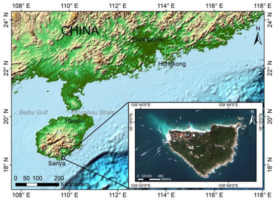
Figure 1.
Location of Wuzhizhou Island.
The remote sensing dataset includes four HR images, which were captured by WorldView-3 (WV3) on 10 February 2018 and by WorldView-2 (WV2) on 28 October 2019, 6 April 2020, and 25 November 2020. The WV2 and WV3 satellites provide 8-band multispectral images with a resolution of 2 m and a panchromatic image with a resolution of 0.5 m.
Details of the WV2 and WV3 images are listed in Table 1, along with cloud coverage and solar elevation angle.

Table 1.
Worldview dataset of Wuzhizhou Island.
Since ICESat-2 Lidar did not cover the Wuzhizhou Island area, the airborne LiDAR data were utilized as the validation data for bathymetry (Figure 2). Airborne LiDAR measures instantaneous height from the target over the area of Wuzhizhou Island, which is then corrected for bathymetry data by assuming a shoreline water depth value of around 0 m. The airborne LiDAR results were classified into five classes by Nature Breaks (Jenks) to maximize the differences between classes. The statistical properties of the Airborne LiDAR are shown in Table 2. The measured vertical and horizontal hydrographic accuracies of the airborne LiDAR were 0.23 and 0.26 m, respectively [23].
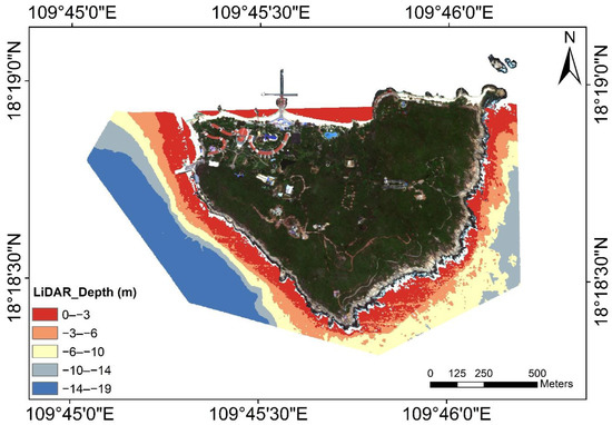
Figure 2.
Airborne LiDAR elevation data of Wuzhizhou Island.

Table 2.
Airborne LiDAR point cloud statistics. Units: m.
3. Pre-Processing
3.1. Overview
The workflow (Figure 3) included two main steps: spectral diffuse attenuation coefficient Kd, and dual-band vector. The study used a dual-band algorithm to inverse water depth. It compared the results with other traditional methods based on real bathymetric data and applied them to the multi-time image data. Finally, the research proposed an improvement in the distinguishing of substrates.
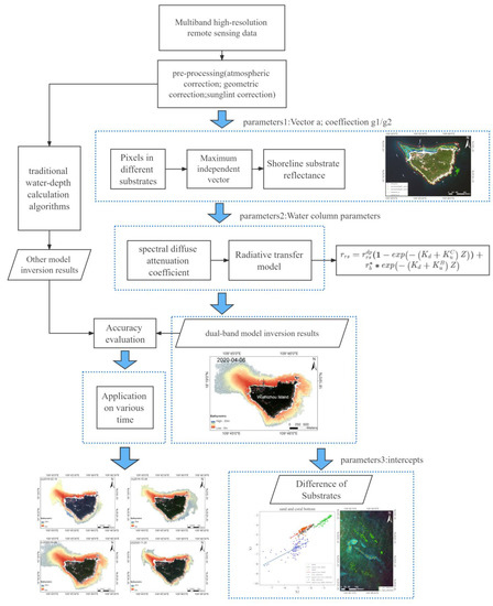
Figure 3.
The workflow of water depth inversion.
Based on the semi-analytical water radiative transfer model proposed by Lee [24,25,26], we used the quasi-analytical algorithm (QAA) and attenuation coefficient algorithm to calculate the inherent optical properties (IOPs) constant of the water column. Assuming that all remote sensing reflections at water depth close to 0 m are from underwater reflections, we calculate remote sensing reflectance of different substrate types around the seashore. Based on the method of optimal band rotation coefficients proposed by Chen [7] and Cheng [20], we assumed the IOPs to be approximately equal in the region and to apply to the whole study area. The results of water quality parameters from the inversion in the optically infinite-depth water region were then used to invert the water depth in the shallow water region. The model used four different time images. Judging and calculating the type of sediment were the next steps.
3.2. Image Pre-Processing
The use of satellite-derived bathymetry requires good atmospheric conditions, negligible solar reflected light, sufficient water transparency, and minimal human influences [27]. The Wuzhizhou Island remote sensing data meet all these requirements.
For the WV2 and WV3 images, the following radiance conversion formula was used:
where L is the radiance of the sensor, DN is the quantized pixel value, absolute factor is the absolute factor, and effective band width is the effective bandwidth of the band.
3.2.1. Atmospheric Correction
The Second Simulation of the Satellite Signal in the Solar Spectrum model (6S model) atmospheric correction was utilized here. The 6S model requires the input of satellite time and target location. It calculates the absorption and Rayleigh scattering of water, carbon dioxide, oxygen, carbon monoxide, nitrous oxide, and other molecules by assuming a cloud-free atmosphere, with the atmospheric model fixed to the tropics and the aerosol model fixed to the ocean. Atmospherically corrected water-leaving reflectance is called .
3.2.2. Sun Glint Correction
According to the Hydrolight water default absorption scattering data, pure water has an absorption coefficient aw of 1 in the near-infrared (Red Edge) of 723 nm. Thus, any signal retained in the NIR channel (after atmospheric correction) mostly represents light reflected from the sea surface in the optical deep-water area, and solar radiation in the NIR band is linearly correlated with solar radiation in the visible band [6,9]. However, the assumption of no water-leaving radiance in the NIR is not valid for very shallow or turbid water or where vegetation influences the bottom reflection. Accordingly, we correct solar glint for the WV2 visible bands by calculating the remote sensing reflectance in the WV2 Red Edge band and NIR band.
Sun glint is a serious confounding factor for remote sensing of water column properties and benthos [28]. The reflected radiance does not contain any information about the water constituents. Hedley [29] used the linear relationships between NIR and visible bands to remove sun glint influences. Goodman et al. [30] used band offset difference. The direct radiance originating from the sun can be reflected on the crest or slope of the wave. Kutser et al. [31] and Doxani et al. [32] improved the multi-band regression model to correct sun glint. Zoffoli et al. [33] separated signals from the water column and seabed while shelving the atmospheric correction problem to better discriminate different bottom classes.
The Goodman method forces the corrected radiance to approach zero at 750 nm [30]. However, in shallow water, the offset allows it to be slightly above zero. We used as the target band.
The Hedley approach selects regions of the image to scale the relationship between the NIR signal and sun glint [28]. The minimum NIR value and least squares were used to calculate the relationship between and NIR bands.
where represents the original remote sensing data in band. in (2) and (3) represents the radiation calibration result in band after the atmosphere collection. is the coefficient for the linear regression between and . represents the 832.5 nm wavelength in both WV2 and WV3. represents the minimum value through the whole image.
Figure 4 shows that the difference between results of the Goodman method and Hedley method lies in the degree of smoothness. Both methods are applicable to different areas and can be used to divide the optical deep-water range. Comparing Figure 4b,c, in our opinions, the Goodman method can rectify the obvious errors better than the Hedley method. Therefore, we could use the clip method to eliminate the obvious errors. The Hedley method gives smooth correction results, so it was better for this study. The two methods of sun glint caused different optical deep-water ranges in this study. Our work chose the Hedley sun glint correction method for a smooth result.
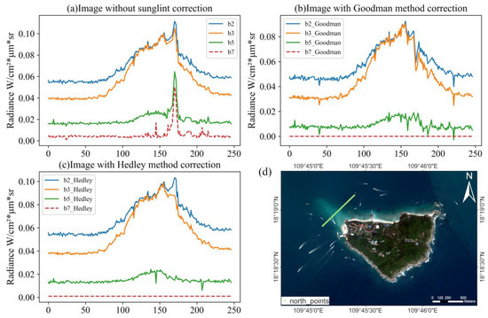
Figure 4.
Images corrected by sun glint correction (a,b) and compared with uncorrected ones (c). Panel (d) shows the unprocessed true color image, and the pixels are obtained along the line from southwest to northeast.
3.2.3. Ship Image Correction
Ship and stern tracks produce waves that reflect solar radiation, resulting in abnormally high remote sensing signals. In this study, we manually identified the hull position and eliminated the ship information in the remote sensing images.
3.2.4. Tide Correction
The tide had a minimum value of 72 cm on 10 February 2018 and a maximum value of 121 cm on 28 October 2019. On the other dates, the value was around 80 cm. The tide data from the Sanya Yalong Port tide detection station were used to correct the bathymetry.
3.2.5. Identification of Optically Shallow Water
Two methods were used to identify optically shallow water around the island. The first was modified normalized difference water index (MNDWI) calculated with green and short-wave infrared 1 (SWIR1) bands to identify the waters. The second was the log-ratio approach using blue and green bands, which is widely used to estimate optical deep-water ranges [13]:
where is water-leaving remote-sensing reflectance. Thus, a threshold is used to identify optically shallow water. When the log-ratio is larger than the preset threshold, the pixel is classified as optically deep water; otherwise, it is classified as optically shallow water. The blue and green bands were applied for clear water around Wuzhizhou Island, and the threshold varied from 1.2 to 1.3 for different remote sensing data [13].
4. Methodology
4.1. Water Column Radiative Transfer Model
Considering the semi-analytical water radiative transfer model of Lee et al. [25], the remotely sensed reflectance is the result of the function:
where is wavelength, is the water absorption proportion, is the water scattering function, is water bottom reflectivity, Z is water depth, is the solar zenith angle, is the angle from the zenith to the satellite, and is satellite azimuth angle. The descriptions and units of these paraments are shown in Table 3.

Table 3.
Variables.
The relationship between remote sensing reflectance of the subsurface () and water-leaving reflectance () can be described as follows:
Based on Lee’s [24,25] single scattering theory, the upward radiation below the water surface can be summed up by the water column and bottom reflection values. The equation of remote sensing reflectivity with water column depth and bottom reflection is:
where is subsurface remote sensing reflectance at infinite depth, and the optical properties of the water body are closest to those of shallow water. , , and are the radiation attenuation coefficients for downward incidence, upward radiation of the water column, and upward radiation of the bottom, respectively. The model assumes that the water bottom is a Lambertian body, and the incident energy is reflected uniformly in all directions. is water bottom reflectivity. and are from the single scattering theory. Thus, = 1.0, and = 1/π.
The theoretical reflectance of different substrates is shown in Figure 5 obtained from Hydrolight simulation. The complex and mixed substrates on the shoreline had varied reflectance, and the value was eliminated with dual-band model by the reflectance on the shoreline.
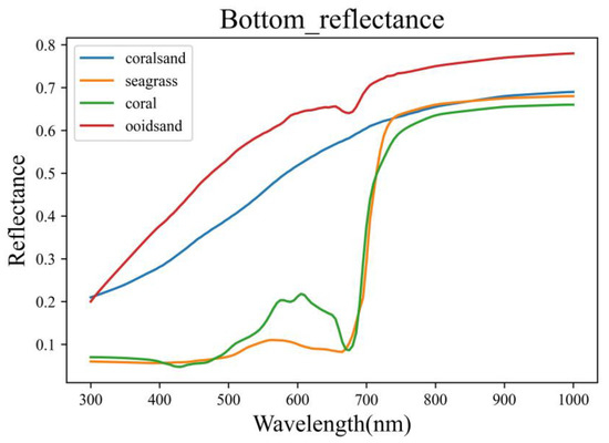
Figure 5.
Bottom reflectance spectrum from Hydrolight.
We assumed that = by introducing ; thus, the function could be written as follows:
Furthermore, the simplified formulas are:
The QAA model was used to calculate absorption coefficient and the backscattering coefficient . Based on absorption coefficient and back-scattering coefficient of pure water, we used the satellite remote sensing reflection data in the QAA model to calculate the actual absorption coefficient and backscattering coefficient of the water body. According to the radiative transfer theory [24,25], the relationship values between the absorption coefficient and backscattering coefficient of the water body are and ; is the Gordon parameter.
The Gordon parameter can be defined as the water absorption coefficient. The water scattering coefficient is a function of the remote sensing reflectance under the water surface. We first calculated the water absorption coefficient () in the green band (555 nm), and all subsequent parameter calculations were established at λ = 555 nm. Using the estimation equation of in the QAA algorithm, we obtained
is the WV spectral absorption function. and represent spectral wavelength ranges of WV in green and red bands, respectively. The absorption coefficient and scattering coefficients of the water are the default values from Hydrolight. is formulated as follows:
4.2. Average Spectral Diffuse Attenuation Coefficient Kd
Let α be the sum of absorption coefficient and back-scattering coefficients of the water column.
where is the downward transmission optical path dissipation factor. It is linearly related to the solar altitude angle:
where and are the scattering factors of the water column and the underwater optical path, respectively. and are obtained by calculating the absorption and scattering coefficient functions of the water body, respectively, which are formulated as follows:
where and are the upstream optical attenuation coefficients of the water column and bottom reflection, respectively. are the same to simplify the equation; and there will be a 10% difference between the two factors.
is the observed zenith angle from the image element position to the satellite position. Radiation has a similar propagation path from the water column and the bottom; thus, .
Kd is a function of incident light, the water absorption coefficient, and the water backscattering coefficient [34]. We recalculated the Kd model suitable for the region based on different acquisition times of remote sensing data and the specific local chlorophyll concentration. Thus, a more accurate model for inversion of Kd was obtained around Wuzhizhou Island.
where is the solar zenith angle. γ in the function are constants. is obtained according to Lee’s simulation. The value of Kd for a particular band is only related to the current band. Based on Lee’s simulation, parameters and γ of the Kd model converge in the derivation process. Parameters , , and in the function are convergence; and γ are simulation results. The Kd model of Lee [34] is applicable to oceanic (Case I) and nearshore (Case II) waters. It is found that there is a bias in the Kd model for Class I water body with low chlorophyll concentration.
Lee [24,25] found that the difference between and is less than 10%, where u(λ) is less than 0.15 in clear water. In this study, multiple WV images had ,:
The semi-analytic bathymetric model can be summarized as shown in Figure 6.
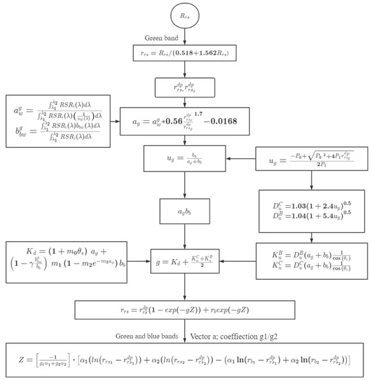
Figure 6.
The bathymetric model based on green- and blue-band remote sensing data. The formulas in the rectangle are deduced by the QAA model and Kd simulations on the green band. is the subsurface remote sensing reflectance. γ are constant values in is the absorption coefficient, and is the scattering coefficient. is the Gordon parameter. is the attenuation coefficient. is the scattering factor of the water column, and is the scattering factor of the underwater optical path. Subscripts 1 and 2 represent the green- and blue-bands, respectively. is the value in optical deep water. Z is water depth.
4.3. Water Depth Digital Elevation
To calculate bathymetric digital elevation, we used a traditional water depth inversion ratio model with an unknown water depth.
where represents water depth; and represent two different bands; , , and n are constants.
We can use (28), without knowing the constants, to find multiple isobaths. This method increases the richness of point selection when calculating multiband vectors, not only limited to coastal but also in deeper water depth (Figure 7c).
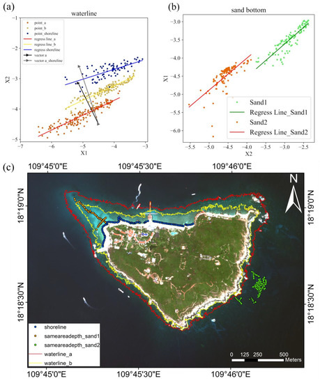
Figure 7.
(a) Linear regression function for the same water depth. (b) Linear regression function g1/g2 for the same substrate type. (c) Isobath of water depth and point selection.
4.4. Dual-Band Algorithm Bathymetry Model
A more generalized equation for the dual-band linear log model can be written in vector form [12]. We adopted the dual-band model of Chen et al. [7] by introducing the unit vector . Then, we use pairs of points with the same water depth but different substrates based on the isobath. The direction of a unit vector can be rotated, so that the vector is perpendicular to the line connecting the point pairs. The study ensured that the product of the same water depth point and the vector was constant. The product of the point and the vector is only linearly related to the bathymetry value, so the sounding and sediment signals could be decomposed.
The vector is perpendicular to the linear regression result of X1, X2 of the two bands in (12). Only Z is constant at the same location in the image element, and there exist different representing different bands.
where represent the blue band; and represent the green band. is obtained from the water radiative transfer model. We simplified the calculation of by calculating . Then, the bathymetric is calculated by substituting into the water depth inversion formula.
When Z is equal to zero, the selection points are on the shoreline of the island. Then is equal to . So, by calculating the value of , we can get rid of calculating the result of and eliminate the ρ value variation caused by different bottom types.
For adjacent pixels with the same water depth but different bottom type, makes maximally correlated with water depth and maximally uncorrelated with substrate type.
For the same type of seabed type, while = :
The radiance data are from the same point, so the formula has the same Z value.
is a constant value in the same sea bottom type. The linear regression coefficients of X1, X2 are at different depths with the same seabed type.
5. Bathymetric Inversion Results
5.1. Evaluation of Inversion Results
We selected the reflectance data where water depth is 0 m. The WV multi-spectral images were utilized to delineate the coastline of Wuzhizhou Island in more detail for determining the shoreline location (Figure 7c). The results of the water inversion are shown in Figure 8. The root mean square errors (RMSEs) of the results are shown in Table 4 and Table 5.
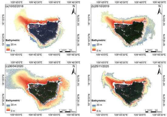
Figure 8.
Inversion results of the bathymetry of Wuzhizhou Island. The inversion water depth is in range of 0 − 20 m. (a) Inversion result by WV2 remote sensing data on 10/02/2018; (b) Inversion result by WV3 remote sensing data on 28/10/2019; (c) Inversion result by WV3 remote sensing data on 06/04/2020; (d) Inversion result by WV3 remote sensing data on 25/11/2020.

Table 4.
RMSEs in different areas. Units: m.

Table 5.
RMSEs of different water depth ranges. Units: m.
The shallow water depth along the coast of Wuzhizhou Island was calculated from the HR remote sensing data using the dual-band bathymetric inversion algorithm (Figure 7). The red area represents the shallow water of 0 m, the yellow area represents the water depth around 5 m, and the blue area represents the optical deep-water area of 20 m. The best inversion effect was from the remote sensing data of 6 April 2020, which had an optical deep-water area completely surrounding Wuzhizhou Island. The rest of the time, the optical deep water did not completely surround Wuzhizhou Island due to different sea-surface factors. The water depth in the northwest of Wuzhizhou Island was relatively shallow. Due to waves and other factors, the image optical deep water could not accurately be separated from the northern sea area. We chose similar optical deep-water ranges and ensured the depth inversion results surrounding the whole island.
The instantaneous shoreline was obtained at the time when the image was captured to correct the instantaneous water depth. The linear regression function of X1X2 was obtained from the same water depth, and then the unit vector was vertical to the X1X2 linear regression line (Figure 7a).
The inversion depth points were selected surrounding the shoreline, isobath, optical deep water, and the adjacent area. The isobath of water depth was combined with the shoreline to improve the accuracy of water depth inversion. The inversion range varied because the optical deep-water location varied with time.
The pixels along isobath and shoreline (Figure 7c) were used to calculate vector (Figure 7a). These points along the contour had the same water depth, and the was distinct. The values around the seashore were utilized to keep the result accurate in shallow water. The same substrate type with different water depths can be used to calculate the ratio of g1 and g2. Equation (33) shows that the ratio of g1 and g2 is equal to the slope of X1 and X2 (Figure 7b).
In Figure 7, the blue line is different from the yellow and red lines. The shoreline substrates were mainly sand, and the isopleth of water depth in deep water had various substrates. Different isopleths of water depth have the same coefficient value, so it is more applicable in water depth inversion.
The inverse results calculated by the shoreline and isopleth of water depth points are shown in Figure 7. The error analysis shown in Figure 7 was obtained by the tidal-corrected LiDAR bathymetric results.
We calculated the bathymetry results around Wuzhizhou Island and obtained parameters in this model. When the water depth is 0 m, the value of is equal to zero. This method can simplify in the formula by selecting the water depth point at the coastal location [7].
The regression was calculated by using the remote sensing images, and the value was substituted into the water depth calculation formula. The water depth parameters are listed in Table 6.

Table 6.
Water depth parameters.
The bathymetry results were compared with the tidally corrected LiDAR bathymetry values to calculate the accuracy of the inversion results in Figure 9.
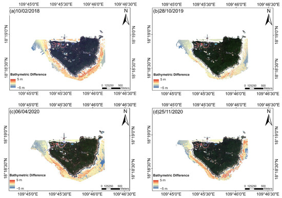
Figure 9.
Bathymetric difference between the inverse bathymetry results and airborne LiDAR results. The results were calculated by bathymetry inversion minus LiDAR bathymetry. The visual red area represents the bathymetric difference of 5 m, the yellow area represents the bathymetric difference of 0 m, and the blue area represents the bathymetric difference of −5 m. (a) Difference between inversion water depth and airborne LiDAR water depth on 10/02/2018; (b) Difference between inversion water depth and airborne LiDAR water depth on 28/10/2019; (c) Difference between inversion water depth and airborne LiDAR water depth on 06/04/2020; (d) Difference between inversion water depth and airborne LiDAR water depth on 25/11/2020.
Another way to analyze the difference between the bathymetry inversion results and the true bathymetry values is to use the RMSE.
In Table 4 and Table 5, the RMSE values are related to water depth distribution. The results had high accuracy when the water depth was less than 10 m. Compared with the traditional water depth inversion method, the overall accuracy of our inversion results was higher. The highest accuracy of the bathymetry inversion results was in the northern area because it had the weakest currents and little sea-surface undulation. The maximum RMSE was in the eastern area because it was highly influenced by the South China Sea Warm Current [35], with active dynamics, large sea-surface undulation, and significant noise off the southern cliff.
The inversion results on 6 April 2020 had the highest accuracy among the four results on different dates. The noise phenomenon caused by the white-cap effect was weak with weak ocean currents. The inversion results were least affected by sea-surface undulations.
5.2. Evaluation of Water Column Spectral Characteristics
The Hydrolight simulation parameters were selected as follows: pure water; Case-I water bodies with chlorophyll a below 0.5 mg/m3; and the concentration of chlorophyll a at 0.01, 0.05, 0.3, and 0.5 mg/m3. Table 7 lists the parameters of Hydrolight simulation using physical data from local waters. Physical parameters in Table 7 and the sun elevation in Table 1 are required by Hydrolight simulations. Table 8 shows the simulation results of the Kd model with Lee’s simulation.

Table 7.
Physical parameters of Wuzhizhou Island selected for Hydrolight simulations of water depth off Wuzhizhou Island.

Table 8.
Hydrolight simulation results.
Lee [34] kept the same values for m0, m2, and m3 to achieve convergence when deriving model parameters. We also kept m0, m2, and m3 the same and used the current physical parameters of the water surface for Hydrolight simulations; then we obtained different results from Lee [34].
Figure 10 compares the Hydrolight simulation results with our calculation results.
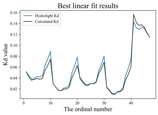
Figure 10.
Best linear fit results. The grey line is the Hydrolight value, and the black line is the calculated value. The vertical axis is the Kd value, and the horizontal axis is the serial number of the fitted points.
In this study, the Kd model coefficients were re-simulated by using the physical data at the times of image acquisition, which could more accurately calculate the Kd value for Case-I water bodies in the study area.
6. Discussion
6.1. Comparison with Other Bathymetry Model Results
Theoretically, bathymetry regression depends on the measured bathymetry data by the regression model. Accordingly, the semi-analytical and semi-empirical algorithms can substitute the manual measurement of water depth, which only depend on the satellite remote sensing data.
6.1.1. Comparison with Other Bathymetry Models
The classic linear regression model can invert the bathymetry when the measured bathymetry value is known. Comparison of the inverse bathymetry values using the linear regression model with the radiative transfer model of the water column is used to evaluate the accuracy of different methods. Table 9 indicates that the substrate-independent model can still give high-level inversion bathymetry results without actual measurements.

Table 9.
Comparison of inversion bathymetry results of remote sensing images by different models using Wuzhizhou Island. Units: m.
Table 9 and Table 10 include different ways to calculate water depth off Wuzhizhou Island. We used a single-band regression model and a multi-band regression model to calculate the bathymetric inversion results based on the known bathymetric data from LiDAR of Wuzhizhou Island. Lyzenga [36] proposed a multi-band inversion model:
where Z is water depth, L is the off-water irradiance corresponding to the band λ, a0 and ai are the regression modelling coefficients, n is the number of bands, and is the remote reflectance at the optically infinite depth water location. The single-band log-linear model uses the green band (550 nm), and the multi-band log-linear model uses blue (470 nm), green (550 nm), and red (650 nm) bands.

Table 10.
Comparison of different performance metrics of inversion bathymetry results by different models. Units: m.
The results of water depth inversion were compared between the linear regression model and the semi-analytical semi-empirical model. The linear regression model requires measured bathymetry results as regression parameters, whereas the measured bathymetry results at various times are difficult in reality.
The points number in the Airborne LiDAR point cloud is nearly 1,000,000. We randomly numbered all points from 1 to 10,000 and screened the same number points from the point cloud, so that 1000 points were used for regression and 500 points were used for validation. The results of the inversion of the water depth were calculated by using Lyzenga’s formulas [36]. Table 9 shows the accuracy of the bathymetrical inversion results of the semi-analytical and semi-empirical model after improving the Kd value, which was better than that of the single-band and multi-band logistic regression models.
6.1.2. Comparison with Dual-Band Bathymetric Inversion Method
We used water depth digital elevation calculated by a traditional water depth inversion ratio model with unknown water depth.
The water depth calculated by the shoreline points in Chen’s model is accurate in shallow water but has a large deviation in deep water. The result calculated by water depth digital elevation points selection is more accurate in deep water than results by shoreline points selection.
We divided the island inversion water depths into four layers according to the number of effective point values, and each layer had about 20,000 grids. The comparison is shown in Table 11. Chen’s method is superior to the method of this current study in the range of 0–2 m layer, but is inferior in areas with water depths greater than 2 m.

Table 11.
Comparison of RMSEs between two methods. Units: m.
6.2. Comparison of Different Substrates
Bathymetric inversion needs the reflection from the same substrate and various depths. In this study, the coral sand was considered as the bottom of the Lambertian body.
According to Lyzenga’s model, the connection between the radiance and water depth is influenced by the optical sensor and bottom reflectance:
where is the radiance value in band i; is the optically infinite depth water radiance without water surface and atmosphere affections; is the solar irradiance, atmosphere transmittance, or water surface transmittance; is the bottom influence; is the spectral diffuse attenuation coefficient of the water; is a coefficient of path length; and Z is water depth.
Lyzenga and Sagawa [37,38] proposed a depth-invariant index to remove light scattering and absorption effects. The index Y is expressed as follows:
Equation (37) is used to calculate the Y value with the selection of the same substrate type and known water depth, where i and j represent the i band and j band, respectively. , , , and Z have the same values as those in (25) and (36).
According to (37), the depth-invariant index Y is a function of , , and . The parameters of (30) are acquired by fitting the data of different regions. This method can preliminarily judge the sediment type according to the constant water depth index when the actual substrate is unknown. Y is greatly affected by image quality, and its value fluctuates significantly in four varying images. Therefore, a better method of sediment type is proposed.
The intercept can be obtained according to the X1X2 linear regression equation, which consists of the prime reflectance of the two bands. The same intercepts represent the same substrate, and different intercepts represent different substrates.
The substrates around the Wuzhizhou Island are complex and mix. We assume the high reflection area and low reflection area have different substrates.
A high reflection area is selected in Figure 11b. Sand1 and Sand2 are selected in Figure 7c. The high reflection area and Sand2 can be classified as one substrate because their intercept values are similar. Sand2 is not the same substrate type as Sand1. Furthermore, all the sand substrates are different from the low reflection areas in Figure 11a. By determining the type of substrate, one can select the points selection with different substrates.
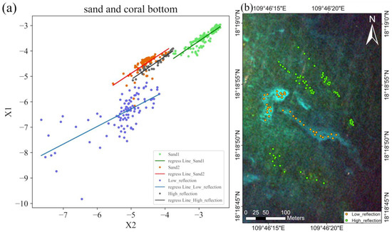
Figure 11.
Intercept representing different substrates. (a) Different substrate types points selection (b). The location of selected points for substrates with high reflectance and substrates with low reflectance.
6.3. Adjacent Pixels Determined by Substrate Types
Based on the method of distinguishing substrates, the same points of different depths of the adjacent sediment in the south area were selected. The pairs of points were used for pointing out the area with same water depth and different substrates.
The pairs of points selected with the same depths of different substrate types were utilized to calculate the vector in the dual-band algorithm model. Figure 12 displays the selected points for the relatively deeper optical shallow water locations in the southeastern area of Wuzhizhou Island. It has a maximum difference in substrates by manual identification.
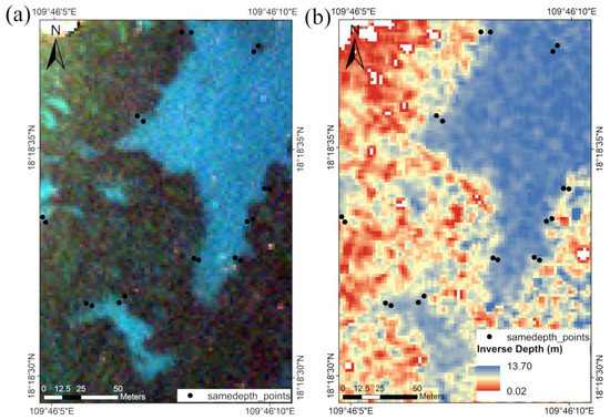
Figure 12.
Comparison of remote sensing images and bathymetry inversion results in the southeastern waters of Wuzhizhou Island. (a) Image in the southeast; (b) inverse water depth.
The results of the adjacent points can overcome the influence of strong reflection substrates on the results of bathymetric inversion. The relative error method is used to confirm the correctness of the results (Figure 13b).
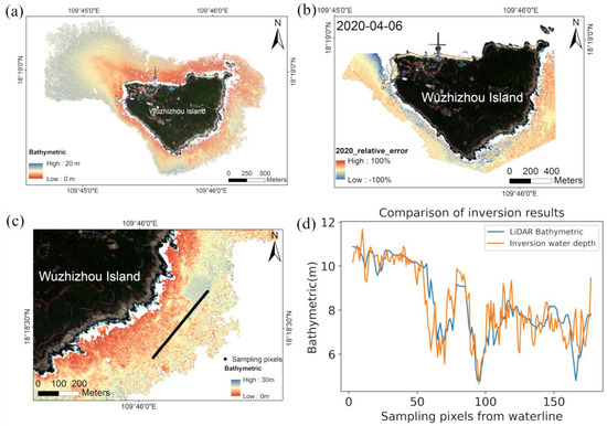
Figure 13.
Comparison of remote sensing images and bathymetry inversion results in the southeastern waters of Wuzhizhou Island: (a) bathymetric, (b) relative error with east points, (c) sampling pixels in east area, (d) comparison of inversion and LiDAR.
Compared with the inversion result, which are gained along the coastline in Figure 7c, the vector has improved inversion results in the optically shallow water area. The selection points method that uses the known substrate types can effectively avoid the interference of substrate spectra compared with the result in Figure 8c and Figure 13a. The method has good applicability when applied to the complex substrate type region in the southeastern part of Wuzhizhou Island. However, it cannot be extended to the whole island because the whole island cannot be separated accurately by artificial vision; Moreover, the vector and Kd results are only suitable for this study region.
This method improves the accuracy of inversion results in optically shallow water at a deeper depth and ensures its accuracy in shallow water. We also adopted the points selection method with known water depth location and corrected the no-ground-truth method bathymetric results in the area with strong substrate reflection (i.e., the southeastern part of Wuzhizhou Island).
6.4. Influence of Optical Properties of Shallow Water
We use the classic model in Hydrolight to calculate the IOPs data. The classic model has two components, namely, pure water, and the particles of chlorophyll-bearing and the chromophoric dissolved organic matter (CDOM). The changes in its optical properties are mainly determined by phytoplankton and their appendages. When a large amount of suspended sediment and chlorophyll a are present in the water, they affect the water quality and the accuracy of bathymetric inversion results. Coastal blue and red bands are sensitive to suspended sediment concentration, and a linear combination of these bands is used to form the suspended sediment inversion model.
The suspended sediment content in the water around Wuzhizhou Island was less than 0.3 mg/L in the image inversion on 6 April 2018, which conforms to the classification criteria of Case-I water. The low content of suspended sediment ensured that the suspended sediment interfered less with the results when we calculated the radiative transfer model of the water column.
We used MODIS inversion of chlorophyll a concentration results with determined time and location. The chlorophyll a concentration in the Wuzhizhou sea area was lower than 0.2 mg/L. There was a significant difference in water quality at different times. The Wuzhizhou Island area was Case-I water on 6 April 2018 (Figure 14). We introduced the chlorophyll a results from MODIS into the Hydrolight model to calculate the Kd model, which ensured that the Kd model is practical in the Wuzhizhou Island Sea area.
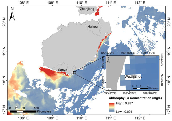
Figure 14.
Chlorophyll a concentration in the water around Wuzhizhou Island on 8 April 2018.
7. Conclusions
Based on HR remote sensing images, we improved Chen’s dual-band bathymetric inversion method and improve Lee’s Kd model applicability. The results around Wuzhizhou Island are utilized to show the applicability and extensibility of the study. Specifically, the value of is calculated from remote sensing data. Each parameter in the radiative transfer model of the water body is also calculated. Then, the shallow water optical properties are obtained for the water surrounding the island using four different images. The bathymetric result is inversed by using the parameters of water body and remote sensing data.
We calculate the vector by using two-adjacent points with different substrates at the same water depth. Points of different sediment types in both optical shallow water and the isopleth of water depth are utilized in this study. Compared with Chen’s model, this method ensures the accuracy of water depth results in optically shallow water and improves the accuracy of water depth results near the optically shallow water. Furthermore, zero depth seabed reflectivity points are selected to separate substrate and water depth signals, which ensures that the inversion of water is equal to zero.
These results confirm that the improved dual-band model is reliable in HR remote sensing bathymetry inversion and has high correctness for shallow water. The simulation manner has good performance in inversing water depth without bathymetric data. The dual-band model with bathymetric contours has more accurate and extensive applications. Four remote sensing images illustrate universal applicability of the dual-band model under different image conditions. The bathymetric inversion results over the four remote sensing images of Wuzhizhou Island are close to the actual values in shallow water from airborne LiDAR data.
Due to some other influences (peculiar reflection, white caps, waves, etc.), there are numerous noise factors at the ocean surface, which may affect depth inversion results. We plan to focus on the inversion of water depth with higher quality remote sensing images for excluding the effect of sea surface noise anomalies on the results. We also plan to study the classification of substrates. According to the linear regression model intercept method, the type of substrate around the island can be divided.
Our work improves the previous research and the accuracy of the dual-band model in water inversion in shallow water with relatively turbid water. In fact, the accuracy of estimated water depth would decline with more variations. This study could not extremely accurately simulate the entire depth of water from shallow water to deep water but could avoid the influence of different substrates.
Author Contributions
Conceptualization, J.C. and Q.Y.; methodology, Q.Y., J.C. and B.C.; data analysis, Q.Y.; investigation, J.C. and Q.Y. resources, B.T., B.C. and J.C.; writing Q.Y. and J.C.; supervision, J.C.; project administration, J.C.; funding acquisition, J.C. All authors have read and agreed to the published version of the manuscript.
Funding
This research was funded by the NSFC-Zhejiang Joint Fund for the Integration of Industrialization and Informatization (Grant No. U1609202), the National Key Research and Development Program of China (Grant No. 2016YFC1400903), the Project of State Key Laboratory of Satellite Ocean Environment Dynamics, Second Institute of Oceanography (No. SOEDZZ2203), the National High Resolution Special Research under Grant 41-Y30F07-9001-20/22; the Scientific Research Foundation of Third Institute of Oceanography, MNR, No. 2020011; and the National Natural Science Foundation of China (Grant Nos. 41376184 and 40976109).
Data Availability Statement
Not applicable.
Conflicts of Interest
The authors declare no conflict of interest.
References
- Burgan, H.I.; Icaga, Y. Flood analysis using adaptive hydraulics (AdH) model in Akarcay Basin. Tek. Dergi 2019, 30, 9029–9051. [Google Scholar] [CrossRef]
- LaFrance Bartley, M.; King, J.W.; Oakley, B.A.; Caccioppoli, B.J. Post-Hurricane Sandy Benthic Habitat Mapping at Fire Island National Seashore, New York, USA, Utilizing the Coastal and Marine Ecological Classification Standard (CMECS). Estuaries Coasts 2022, 45, 1070–1094. [Google Scholar] [CrossRef]
- Mayer, L.; Jakobsson, M.; Allen, G.; Dorschel, B.; Falconer, R.; Ferrini, V.; Lamarche, G.; Snaith, H.; Weatherall, P. The Nippon Foundation—GEBCO seabed 2030 project: The quest to see the world’s oceans completely mapped by 2030. Geosciences 2018, 8, 63. [Google Scholar] [CrossRef]
- Liu, Y.M.; Deng, R.R.; Qin, Y.; Liang, Y.H. Data processing methods and applications of airborne LiDAR bathymetry. J. Remote Sens. 2017, 21, 982–995. [Google Scholar]
- Chen, Q.D.; Deng, R.R.; Qin, Y.; He, Y.; Wang, W. Water depth extraction from remote sensing image in Feilaixia reservoir. Acta Sci. Nat. Univ. Sunyatseni 2012, 51, 122–127. [Google Scholar]
- Kutser, T.; Hedley, J.; Giardino, C.; Roelfsema, C.; Brando, V.E. Remote sensing of shallow waters–A 50 year retrospective and future directions. Remote Sens. Environ. 2020, 240, 111619. [Google Scholar] [CrossRef]
- Chen, B.; Yang, Y.; Xu, D.; Huang, E. A dual band algorithm for shallow water depth retrieval from high spatial resolution imagery with no ground truth. ISPRS J. Photogramm. Remote Sens. 2019, 151, 1–13. [Google Scholar] [CrossRef]
- Cao, B.; Deng, R.; Zhu, S.; Liu, Y.; Liang, Y.; Xiong, L. Bathymetric Retrieval Selectively Using Multiangular High-Spatial-Resolution Satellite Imagery. IEEE J. Sel. Top. Appl. Earth Obs. Remote Sens. 2020, 14, 1060–1074. [Google Scholar] [CrossRef]
- Liu, Y.; Zhao, J.; Deng, R.; Liang, Y.; Gao, Y.; Chen, Q.; Xiong, L.; Liu, Y.; Tang, Y.; Tang, D. A downscaled bathymetric mapping approach combining multitemporal Landsat-8 and high spatial resolution imagery: Demonstrations from clear to turbid waters. ISPRS J. Photogramm. Remote Sens. 2021, 180, 65–81. [Google Scholar] [CrossRef]
- Leu, L.-G.; Chang, H.-W. Remotely sensing in detecting the water depths and bed load of shallow waters and their changes. Ocean. Eng. 2005, 32, 1174–1198. [Google Scholar] [CrossRef]
- Lyzenga, D.R. Passive remote sensing techniques for mapping water depth and bottom features. Appl. Opt. 1978, 17, 379–383. [Google Scholar] [CrossRef]
- Philpot, W.D. Bathymetric mapping with passive multispectral imagery. Appl. Opt. 1989, 28, 1569–1578. [Google Scholar] [CrossRef]
- Stumpf, R.P.; Holderied, K.; Sinclair, M. Determination of water depth with high-resolution satellite imagery over variable bottom types. Limnol. Oceanogr. 2003, 48, 547–556. [Google Scholar] [CrossRef]
- Fournier, G.; Ardouin, J.-P.; Levesque, M. Modeling Sea Bottom Hyperspectral Reflectance. Appl. Sci. 2018, 8, 2680. [Google Scholar] [CrossRef]
- Ma, Y.; Xu, N.; Liu, Z.; Yang, B.; Yang, F.; Wang, X.H.; Li, S. Satellite-derived bathymetry using the ICESat-2 lidar and Sentinel-2 imagery datasets. Remote Sens. Environ. 2020, 250, 112047. [Google Scholar] [CrossRef]
- Cao, B.; Fang, Y.; Gao, L.; Hu, H.; Jiang, Z.; Sun, B.; Lou, L. An active-passive fusion strategy and accuracy evaluation for shallow water bathymetry based on ICESat-2 ATLAS laser point cloud and satellite remote sensing imagery. Int. J. Remote Sens. 2021, 42, 2783–2806. [Google Scholar] [CrossRef]
- Chen, Q.; Deng, R.; Chen, L.; Qin, Y.; He, Y.; Tian, J. Atmospheric correction of WorldView-2 data for the Xisha Islands and reefs imagery. J. Trop. Oceanogr. 2014, 33, 88–94. [Google Scholar]
- Huang, R.; Yu, K.; Wang, Y.; Wang, J.; Mu, L.; Wang, W. Bathymetry of the coral reefs of Weizhou Island based on multispectral satellite images. Remote Sens. 2017, 9, 750. [Google Scholar] [CrossRef]
- Xia, H.; Li, X.; Zhang, H.; Wang, J.; Lou, X.; Fan, K.; Shi, A.; Li, D. A bathymetry mapping approach combining log-ratio and semianalytical models using four-band multispectral imagery without ground data. IEEE Trans. Geosci. Remote Sens. 2019, 58, 2695–2709. [Google Scholar] [CrossRef]
- Cheng, J.; Ma, Y.; Zhang, J. Water-depth-zoning inversion based on the relationship between two-band radiance data and the depth-invariant index. Reg. Stud. Mar. Sci. 2021, 44, 101790. [Google Scholar] [CrossRef]
- Wu, Z.; Chen, S.; Chen, M.; Li, Y.; Wang, Q.; Wang, D. Preliminary survey and analysis of the resources of hermatypic corals in Hainan Island. Trans. Oceanol. Limnol. 2013, 2, 44–50. [Google Scholar]
- Huang, J.; Wang, F.; Zhao, H.; Xu, H.; Liu, S.; Xu, Q.; Wang, A.; Li, X. Reef benthic composition and coral communities at the Wuzhizhou Island in the South China Sea: The impacts of anthropogenic disturbance. Estuar. Coast. Shelf Sci. 2020, 243, 106863. [Google Scholar] [CrossRef]
- He, Y.; Hu, S.J.; Chen, W.B.; Zhu, X.; Wang, Y.; Yang, Z.; Zhu, X.; Lyu, D.; Yu, J.; Huang, T. Research progress of domestic airborne dual-frequency LiDAR detection technology. Laser Optoelectron. Prog 2018, 55, 2019. [Google Scholar]
- Lee, Z.; Carder, K.L.; Mobley, C.D.; Steward, R.G.; Patch, J.S. Hyperspectral remote sensing for shallow waters. I. A semianalytical model. Appl. Opt. 1998, 37, 6329–6338. [Google Scholar] [CrossRef]
- Lee, Z.; Carder, K.L.; Mobley, C.D.; Steward, R.G.; Patch, J.S. Hyperspectral remote sensing for shallow waters: 2. Deriving bottom depths and water properties by optimization. Appl. Opt. 1999, 38, 3831–3843. [Google Scholar] [CrossRef]
- Lee, Z.; Shang, S.; Qi, L.; Yan, J.; Lin, G. A semi-analytical scheme to estimate Secchi-disk depth from Landsat-8 measurements. Remote Sens. Environ. 2016, 177, 101–106. [Google Scholar] [CrossRef]
- Caballero, I.; Stumpf, R.P. On the use of Sentinel-2 satellites and lidar surveys for the change detection of shallow bathymetry: The case study of North Carolina inlets. Coast. Eng. 2021, 169, 103936. [Google Scholar] [CrossRef]
- Kay, S.; Hedley, J.D.; Lavender, S. Sun glint correction of high and low spatial resolution images of aquatic scenes: A review of methods for visible and near-infrared wavelengths. Remote Sens. 2009, 1, 697–730. [Google Scholar] [CrossRef]
- Hedley, J.; Harborne, A.; Mumby, P. Simple and robust removal of sun glint for mapping shallow-water benthos. Int. J. Remote Sens. 2005, 26, 2107–2112. [Google Scholar] [CrossRef]
- Goodman, J.A.; Lee, Z.; Ustin, S.L. Influence of atmospheric and sea-surface corrections on retrieval of bottom depth and reflectance using a semi-analytical model: A case study in Kaneohe Bay, Hawaii. Appl. Opt. 2008, 47, F1–F11. [Google Scholar] [CrossRef]
- Kutser, T.; Vahtmäe, E.; Praks, J. A sun glint correction method for hyperspectral imagery containing areas with non-negligible water leaving NIR signal. Remote Sens. Environ. 2009, 113, 2267–2274. [Google Scholar] [CrossRef]
- Doxani, G.; Papadopoulou, M.; Lafazani, P.; Tsakiri-Strati, M.; Mavridou, E. Sun glint correction of very high spatial resolution images. In Thales, in Honor of Prof. Emeritus Michael E. Contadakis; Arabelos, D.N., Kaltsikis, C., Spatalas, S., Tziavos, I.N., Eds.; Astrophysics Data System: Cambridge, MA, USA, 2013; pp. 329–340. [Google Scholar]
- Zoffoli, M.L.; Frouin, R.; Kampel, M. Water column correction for coral reef studies by remote sensing. Sensors 2014, 14, 16881–16931. [Google Scholar] [CrossRef]
- Lee, Z.; Hu, C.; Shang, S.; Du, K.; Lewis, M.; Arnone, R.; Brewin, R. Penetration of UV-visible solar radiation in the global oceans: Insights from ocean color remote sensing. J. Geophys. Res. Ocean. 2013, 118, 4241–4255. [Google Scholar] [CrossRef]
- Shu, Y.; Wang, Q.; Zu, T. Progress on shelf and slope circulation in the northern South China Sea. Sci. China Earth Sci. 2018, 61, 560–571. [Google Scholar] [CrossRef]
- Lyzenga, D.R. Shallow-water bathymetry using combined lidar and passive multispectral scanner data. Int. J. Remote Sens. 1985, 6, 115–125. [Google Scholar] [CrossRef]
- Lyzenga, D.R. Remote sensing of bottom reflectance and water attenuation parameters in shallow water using aircraft and Landsat data. Int. J. Remote Sens. 1981, 2, 71–82. [Google Scholar] [CrossRef]
- Sagawa, T.; Boisnier, E.; Komatsu, T.; Mustapha, K.B.; Hattour, A.; Kosaka, N.; Miyazaki, S. Using bottom surface reflectance to map coastal marine areas: A new application method for Lyzenga’s model. Int. J. Remote Sens. 2010, 31, 3051–3064. [Google Scholar] [CrossRef]
Publisher’s Note: MDPI stays neutral with regard to jurisdictional claims in published maps and institutional affiliations. |
© 2022 by the authors. Licensee MDPI, Basel, Switzerland. This article is an open access article distributed under the terms and conditions of the Creative Commons Attribution (CC BY) license (https://creativecommons.org/licenses/by/4.0/).