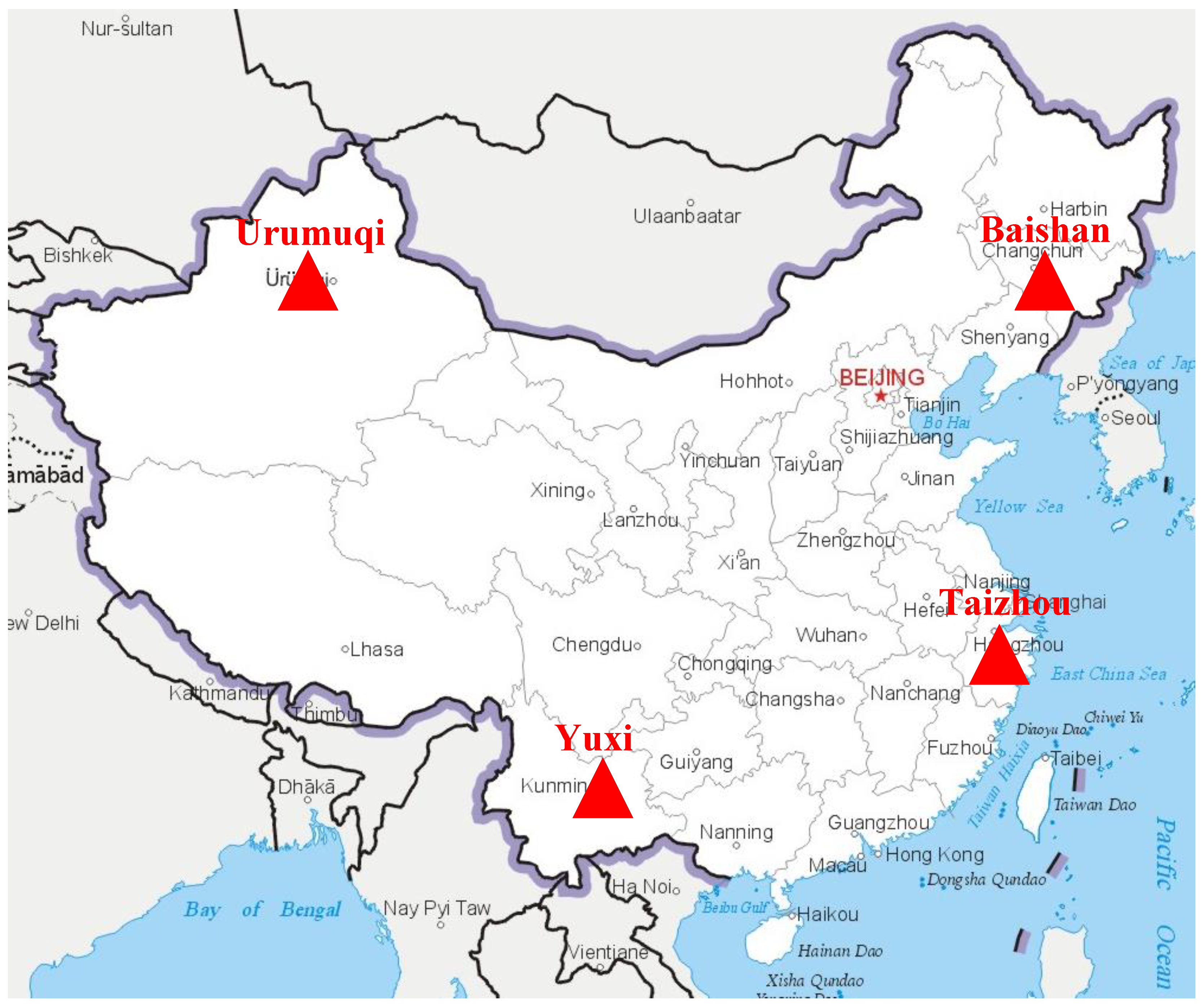
1. Introduction
Electromagnetic waves in the VLF/LF frequency band can travel long distances in the so-called earth-ionosphere waveguide and are widely used in communication, navigation, nuclear electromagnetic pulse detection, lightning detection, etc. [
1,
2,
3,
4]. Among these, lightning detection systems find the locations of sferics by measuring the arrival times of electromagnetic signals and solving the inverse problem with the estimated or empirical propagation velocity of lightning signals. This propagation velocity is the average velocity of the propagated lightning energy for each frequency component and is also known as the group velocity [
5]. The group velocity, which can be further interpreted as time or distance, is one of the most important parameters to be estimated for lightning detection systems.
Although a complete theory of VLF/LF radio wave propagation was established in the 1960s [
6], there is no analytical solution for the group velocity of lightning electromagnetic pulses, especially when considering multiple modes, anisotropic geomagnetic background, a diffuse ionosphere profile, and segmentation propagation path. Wait [
6] derived the phase velocity of the nth-order mode of radio waves passing through the Earth-ionosphere waveguide (EIWG), assuming the Earth and the ionosphere possess infinite conductivity. Later, a non-sharp or diffuse ionosphere with exponentially varying conductivity was considered by Wait to obtain a more accurate analytical solution of the phase velocity. While these simplified versions of phase velocity reveal the underlying physical nature and are convenient for fast computation, they are not sufficiently accurate due to various approximations. A general theory of radio propagation by wave-guide modes is given by Budden [
7] which simultaneously makes allowance for the gradualness of the lowest part of the ionosphere, the Earth’s curvature, and the Earth’s magnetic field. However, this method requires solving partial differential equations and, therefore, also does not yield an analytical solution for the phase or group velocity.
After the development of the detection of lightning discharges in the 1990s, various methods for estimating the group velocity of the lightning waveform were proposed. The World Wide Lightning Location Network (WWLLN) [
8] uses an approximate group velocity of about 0.9922c (0.9922 times the speed of light in vacuum), corresponding to a representative group velocity in the middle of the detection frequency range, for all paths at all times and frequencies, as recommended by Watt [
9]. This fixed group velocity, although partially eliminating the effects of wave propagation on the path, still does not fully reflect the time- and space-dependent properties of the EIWG.
Said et al. [
10] proposed a semi-empirical method for long-range lightning geolocation which avoids explicit estimation of group velocity. This technique catalogs the dominant variation in expected received waveforms in a set of waveform banks, which are then used to estimate the propagation distance and accurately determine the arrival time. Using only three sensors in a trial network, this technique demonstrated a median accuracy of 1–4 km, depending on the time of day. This ingenious method considers the effect of Earth-ionosphere waveguides while avoiding the need to estimate the group velocity. However, this method requires the creation of a filter bank containing a large number of typical lightning waveforms, which is difficult to implement in most scientific and engineering applications.
Liu et al. [
11] proposed a technique with a variable propagation velocity which is implemented in the time of arrival (TOA) method. The lightning locations obtained by this method improve the accuracy of locations by 0.89–1.06 km compared with the lightning locations reported by the UK Met Office. Li et al. [
12] establish a long-range lightning location network to verify the feasibility of the variable propagation velocity proposed by Liu. It is found that the average location error of the equivalent propagation method is 9.17 km, which improves the average location accuracy by about 1.16 km, compared with the assumed light speed of lightning-radiated sferic from the lightning stroke point to the observation station. However, this conceptually novel method makes an implicit assumption that the lightning wave traveling over different paths shares the same propagation velocity, which is not true. It is also not feasible to use different velocities for each path because this would make the number of unknowns in the equations of the TOA method larger than that of observations.
Accurately estimating the group velocity requires high-precision modeling of the propagation of VLF/LF waves. With long wave propagation modeling tools such as LWPC [
13] and appropriate ionospheric models [
14], the phase characteristics of electromagnetic waves can be accurately calculated numerically. For low-power VLF propagation, the ionosphere can be fully characterized by its electron density profile, the corresponding collision frequency profile, and the direction and intensity of the ambient magnetic field. The former two parameters, i.e., the electron density profile and the collision frequency profile, are two of the most important and unstable parameters of the ionosphere D region. Wait and Spies [
15] used laboratory measurements, ionospheric sounding rocket measurements, and VLF propagation measurements to empirically derive a parameterized model with an exponential profile for them. This two-parameter model, which is parameterized by the reference height (
h’) and the slope of the logarithm of the electron density profile (
β), has been widely used and verified in various scenarios since then. Based on previous works, the CCIR recommended typical values for
h’ and
β during the daytime and nighttime. According to this recommendation, the ionospheric parameters are relatively stable during the day and are only affected by the season and latitude. The changes in the ionosphere at night are more complicated. In addition to the seasonal and latitude factors, they are also affected by the working frequency and the geomagnetic field of the location. LWPC also uses Wait’s two-parameter model for the ionosphere, and the values for
h′ and
β are determined by the solar zenith angle, which in turn, is determined by parameters such as time and location [
13]. In the LWPC model, when the solar zenith angle meets the conditions of daytime or nighttime, the corresponding
β and
h′ are both fixed values. Therefore, for such regions, the electron density and collision frequency do not change with the geographical location but are only related to the height from the ground. This is different from the distribution of actual electron density and collision frequency. A more sophisticated model of the ionosphere is needed to facilitate precise modeling of VLF/LF propagation.
The International Reference Ionosphere (IRI) is an empirical standard model of the ionosphere produced by a working group based on all available data sources [
14]. Since the first version of the model was released in the 1960s, it has been widely used in various fields [
16,
17,
18,
19,
20]. Pal [
16] coupled the Fortran code of the IRI model with the LWPC code for propagation simulation of the VLF signal of the Indian Navy’s transmitter (VTX) at 18.2 kHz. The electron-ion density profiles along the propagation path, which are computed from the IRI-2007 model, are used as the inputs in the LWPC code. Chowdhury [
17] uses the electron density profile from the IRI model to fit Wait’s two-parameter exponential model to obtain the values of
h’ and
β, and then uses LWPC to simulate the amplitude variations of the VTX 18.2 kHz signal for comparison with the observations from available VLF/LF sites. Yi [
18] updated both the electron density and collision frequency modules originally embedded in LWPC by the IRI model for improved simulation performance compared with the observed amplitude variations of VLF signals of the Australian Navy’s transmitter (NWC) by the Wuhan University VLF receiver. In addition to the narrowband VLF modeling described above, the IRI model is also used for wideband VLF propagation simulation. Hu [
19] developed a full-wave two-dimensional finite-difference time-domain (FDTD) model to simulate lightning-generated electromagnetic wave propagation in the ionosphere with high altitude and long-distance capabilities. The density and collision frequency profiles of electrons and ions are calculated using the IRI model. Results of this FDTD model agree with the mode theory very well, with the agreement between the models better than 5% over the frequency range from 0 to 30 kHz for typical nighttime ionosphere profiles. Marshall [
20] incorporated the IRI model into a time-domain model of the lightning electromagnetic pulse (EMP) interaction with the lower ionosphere. In addition to modeling lightning, this model can be used for long-distance VLF wave propagation in the Earth-ionosphere waveguide, heating of the lower ionosphere by VLF transmitters, etc. The IRI model is generally considered to be a description of the average and quiet state of the ionosphere. When the ionosphere is disturbed by sudden events such as solar flares, earthquakes, and volcanoes, the ionospheric parameters obtained by the IRI model have great deviations from the real situation. In this case, the real-time ionospheric state parameters can be retrieved by the VLF ionospheric remote sensing method [
21], which is not described here in detail.
Inspired by the previous research results mentioned earlier, this paper develops a lightning positioning scheme with a novel numerical method to estimate the group velocity of the lightning signal during ionospheric quiet periods. The well-known LWPC program is used to model the propagation of the electromagnetic wave at the frequency band of interest, and the IRI-2016 model is incorporated into the numerical modeling process to provide more accurate ionosphere parameters such as the electron density profile. Experimental results of a VLF/LF lightning location network are demonstrated and analyzed to show the effectiveness of our method. Extensive comparisons of lightning location accuracy between our proposed method and others are also made. The results show that when the average ionospheric reflection height on the path is accurately obtained (based on the IRI model), the first-order mode group velocity analytic solution yields a very good localization accuracy. The default LWPC model yields a similar localization accuracy, and the combined use of the LWPC and IRI models allows for further improvement in localization accuracy.
This article is organized as follows. In
Section 2, the background of the lightning location principle, i.e., the TDOA and the arrival time estimation method, is briefly introduced, and the proposed group velocity estimation method applicable to broadband lightning signals is described in detail with an emphasis on the VLF/LF electromagnetic wave propagation modeling scheme based on the LWPC and IRI models. In
Section 3, the performance of our proposed group velocity estimation method is analyzed based on the experimental results of the VLF/LF lightning detection network and compared with other group velocity estimation methods. The results of the analysis are discussed in
Section 4. Finally, conclusions are drawn in
Section 5.
2. Materials and Methods
2.1. Lightning Location via the TDOA Method
Suppose the position of lightning occurrence is (
φ,
λ) where
φ and
λ are latitude and longitude, respectively, and the time of occurrence of the lightning sferic is
T0. The positions of the
N lightning detection stations are (
φn,
λn), and the arrival times of the received lightning are
Tn,
n = 1, 2,…,
N, respectively. The TDOA method estimates the lightning position and time of occurrence by minimizing the following cost function:
where
σt,n is the standard deviation of the synchronization time error of the nth receiver, and
D(
φ,
λ,
φn,
λn) and
vn are the distance and the propagation velocity from the lightning location to the nth receiver, respectively. The optimization problem in Equation (1) can be solved by well-established optimization tools such as the Levenberg–Marquardt algorithm [
22].
It can be found from Equation (1) that in addition to the receiver synchronization error
σt,n, the arrival time
Tn and the group velocity
vn are two of the most important factors that affect the lightning location accuracy. Accurate estimation of arrival time can be achieved using the time of group arrival (TOGA) method or cross-correlation described in
Section 2.2. To reduce the location error caused by the inaccuracy of the group velocity, a relocation scheme is adopted. First, the approximate location of the lightning is estimated via Equation (1) using the speed of light in the air, and then the group velocity is estimated using methods described in
Section 2.3 with the approximate location of the lightning event. Finally, a more accurate location of the lightning event is obtained by minimizing Equation (1) again using the estimated group velocity.
2.2. Arrival Time Estimation of Lightning Signals
According to the classic theory of VLF/LF electromagnetic propagation, when the lightning occurs at a short distance to the receiver, the ground wave dominates, and there is a sharp peak in the received time-domain waveform of the lightning electric field. In this case, the time stamp of the electric field waveform peak is commonly used as the arrival time of the lightning, and the location error caused by the inaccuracy of the arrival time is very small. In contrast, when the lightning source is far away from the receiver, due to the filtering effect of the EIWG, the high-frequency components of the lightning electric field are filtered out and the sharp peak is broadened. The time stamp corresponding to the electric field waveform peak should no longer be used as the arrival time of the lightning; otherwise, it causes large arrival time errors, which lead to large location errors.
Two well-known methods can be used to accurately determine the time (difference) of the arrival of long-range lightning fields. One is the cross-correlation method [
23], which calculates the time difference between the arrival of lightning at the two stations by cross-correlating their electric field waveforms. The other is the TOGA method proposed by Dowden et al. [
5], which calculates the group arrival time of the lightning electric field by performing least-squares linear fitting on the phase spectrum and is successfully applied to the WWLLN lightning detection network. The latter method is described in detail since it is very closely related to the group velocity estimation method described in
Section 2.3. The TOGA method is briefly summarized as follows.
The phase of the lightning signal at time
t and distance
r is:
where
ω is the angular frequency,
T0 is the time of lightning occurrence,
k(
ω) is the wave number of the electromagnetic wave, and
ϕ0 is the initial phase of the lightning signal. Note that the above formula assumes that the initial phase of each frequency component of lightning is constant at the time
T0, which is generally true for fast-rising lightning signals. Taking the derivative of the phase to the angular frequency
ω yields the slope of the phase spectrum as:
The last step in Equation (3) uses the definition of group velocity. Group travel time is defined as the time it takes for the lightning signal to travel distance
r at group velocity
vg, i.e.,
tg(
ω) =
r/
vg(
ω). Correspondingly, the group arrival time is defined as
tTOGA(
ω) =
T0 +
tg(
ω). Together with Equation (3) we can immediately obtain:
Therefore, the group arrival time
tTOGA(
ω) can be obtained from the above formula:
The arrival time of the main energy of the broadband lightning electromagnetic pulse, i.e.,
TOGA, is defined as the average of the group arrival time
tTOGA(
ω):
where the bar in Equation (6) implies an average. In practice, a robust estimate of the mean of
tslope(
ω) is replaced by the slope of the regression line of the phase spectrum
ϕ(
ω) in the frequency band of interest. Recall that
t represents the sampling time which can be defined arbitrarily as long as the lightning waveform is completely recorded. Dowden [
5] suggests using the trigger time as the sampling time
t in Equation (6). Since the trigger time is earlier than the
TOGA, the phase spectrum always shows a negative slope for the measured lighting electric waveform.
2.3. Group Velocity Estimation Methods
The group velocity is the velocity with which the envelope of a signal propagates in a medium and it is well-defined for narrowband applications. The spectrum of lightning signals occupies a very wide bandwidth, and the traditional definition of group velocity is no longer applicable. Meanwhile, researchers in the VLF/LF community have found that most of the lightning energy is concentrated in a certain frequency range, and there is a peak point in the spectrum. Therefore, the group velocity at the spectral peak frequency can be used to approximate the group velocity of lightning signals. The phase velocity
vp(
ω) and the group velocity
vg(
ω) for a narrow band of energy centered about frequency
ω are defined as:
Combining Equations (7) and (8) and eliminating
k(
ω), we can obtain the relationship between
vp(
ω) and
vg(
ω) as follows:
By assuming the Earth and the ionosphere to possess infinite conductivity, Wait [
15] has shown that the phase velocity of the nth-order mode of radio waves passing through the Earth and a sharply bounded ionosphere is approximately given by:
where
c is the velocity of light in free space,
,
h is the height of reflection of the VLF wave from the ionosphere, and
a and
λ are the Earth’s radius and wavelength of the wave, respectively. Therefore, given the frequency
ω, waveguide mode order
n, and ionospheric reflection height
h, the phase velocity along the path can be calculated from Equation (10), and then the corresponding group velocity can be obtained from Equation (9).
Generally, Equations (9) and (10) are used to estimate the group velocity and phase velocity of the first-order mode for large distances where higher-order modes vanish. For short or medium distances, analytical calculation of the group velocity of lightning sferics by the above method is not feasible due to the superposition of multiple modes. In addition, when the propagation path is long enough that the ionospheric day–night transition occurs, the average reflection height h in Equation (10) is difficult to determine accurately, despite the presence of only the first-order mode.
Since the analytical group velocity of the first-order mode based on the mode theory has the above-mentioned limitations, we propose a novel and more accurate group velocity estimation method applicable to wideband lightning signals. Our proposed method is inspired by the TOGA method mentioned in
Section 2.2 and transforms the problem of solving the group velocity into the problem of solving the group delay time as described below.
First, we rewrite the relation between the group velocity
vg(
ω) and the group travel time
tg(
ω) as follows:
According to the definition of the group velocity, by combining Equations (8) and (11) the group travel time can be reformulated as:
The
term in Equation (12) is the phase change resulting from radio propagation. This phase term cannot be extracted from the experimental data but can be easily obtained by numerical simulations such as those performed using the LWPC program. In particular, the phase spectrum of any frequency calculated by LWPC is the phase relative to the propagation of electromagnetic waves in free space, namely:
where
Tr = r/c. Note that the expression of Equation (13) is a special case of Equation (2) where the initial phase
ϕ0 is set to 0 and the time
t is set to be the instant after the electromagnetic wave travels the distance
r at the speed of light in the vacuum from time
T0. Taking the derivation of (13) about
ω, we obtain:
Combining Equations (12) and (14) we obtain:
The group velocity can be obtained by Equations (11), (14) and (15). To obtain the group velocity of wideband lightning signals, the same measure can be taken as in Equation (6), i.e., either by taking the mean of tslope(ω) or by the least square fitting of the regression line slope of the phase spectrum ϕ(ω) in the frequency band of interest.
The computational procedure of our proposed group velocity estimation method is shown in
Table 1.
2.4. Long Wave Propagation Modeling Based on LWPC and IRI Models
From the previous subsection, it can be seen that the modeling of VLF/LF wave propagation is one of the most important steps in group velocity estimation. The propagation of VLF electromagnetic waves in the Earth-ionospheric waveguide is affected by many factors such as ionospheric parameters, ground parameters, and geomagnetic parameters. Among these space-varying parameters, ground conductivity, permittivity, and geomagnetic field are almost invariant with time, so existing measured or empirical models for them can be used. In contrast, ionospheric parameters vary dramatically not only within a day but also with seasons and years. Meanwhile, ionospheric parameters are also affected by sudden disturbances such as solar flares, volcanic eruptions, earthquakes, etc.
We use the well-known LWPC program for VLF/LF propagation modeling and simulation. LWPC is a very powerful software based on the mode theory [
13]. After the user inputs the location, frequency, time of the source, and the location of the receiving point, the software can automatically determine the ionosphere, ground conductivity, and the Earth’s magnetic field parameters distribution along the path and calculate the field strength and phase at the receiving point.
For the most important ionospheric parameters, i.e., electron density
Ne(
h) and electron-neutral collision frequency
V(
h), LWPC uses the classical Wait two-parameter model exponential model to calculate them:
where
β and
h’ are the electron density slope (km
−1) and reference height (km), respectively. The built-in model of LWPC sets the value of
β and
h’ for the daytime and nighttime ionosphere separately. The daytime ionosphere has a constant value of
β equal to 0.3 km
–1 and a constant value of
h’ equal to 74 km. The nighttime ionosphere is more complicated in that
β varies with frequency while
h’ is constant at 87 km.
Despite the great success of LWPC, the ionosphere model it uses is far from perfect because the electron density does not vary with geographic location when the solar zenith angle meets daytime or nighttime conditions. Following previous works, we combine the IRI-2016 ionospheric model with the LWPC model to obtain better modeling results of VLF electromagnetic wave propagation. Specifically, the electron density profile in Equation (16) is substituted by IRI-2016’s output, and the models of collision frequency, conductivity, permittivity, and geomagnetic field remain unchanged as the built-in models of LWPC. For any given transmitter and receiver pair, the great circle path is divided into no more than 100 equal segments due to the limitations of LWPC. The length of each segment is set to be no less than 50 km, which is a compromise between accuracy and efficiency. The electron density output from the IRI-2016 model is extrapolated down to a height of 65 km employing linear logarithmic interpolation, which is also generally considered to be the lowest height of the ionosphere during the daytime.
2.5. A Detailed Example for Group Velocity Estimation
In this section, we give an example to illustrate how to estimate the group velocity of a lightning signal using our proposed method. A set of data from the lightning detection experiment introduced in
Section 3.1 is used for the following calculations. By TDOA localization with the speed of light in the air, the initial solution of the location (31°3′N, 91°35′E) and the occurrence time (UTC 2021/09/20 08:25:59) of the lightning source are obtained, so that the path from the source to each station can be determined, and the corresponding distances are 1286 km, 1310 km, 2770 km, and 3126 km. The phase spectrums of Equation (13) are calculated using the VLF/LF propagation model introduced in
Section 2.4, as shown by the blue curves in
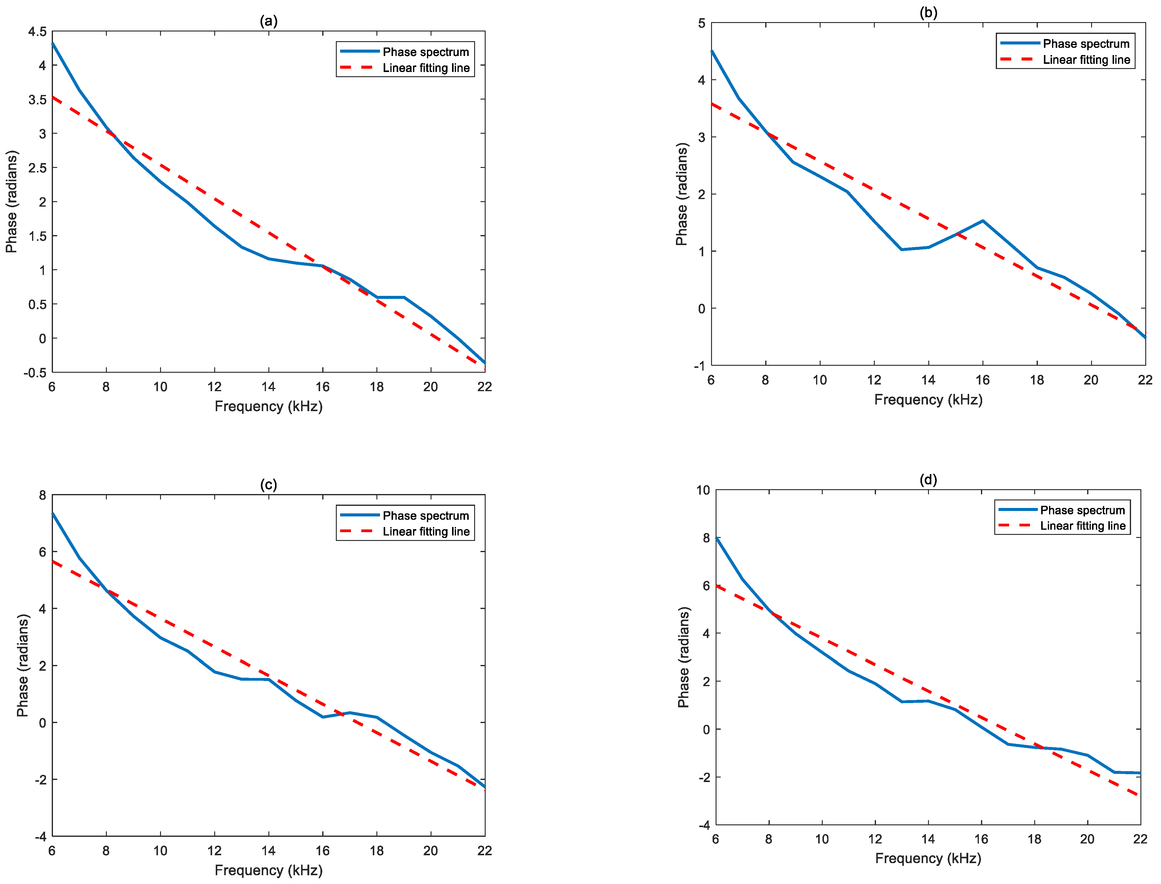
Figure 1. The frequency range of the phase spectrum is from 6 kHz to 22 kHz, covering most of the energy of the lightning signal. The red dotted lines in
Figure 1 are the linear fitting lines of the spectrum curves based on the least square criterion. The linear fitting line with a negative slope indicates that the lightning propagation time along the path is longer than the time required for the electromagnetic wave to travel the same distance in the air, and the time difference equals the slope of the linear fitting line. From
Figure 1 and Equation (2), it can be calculated that the time differences (
tslope) are
,
,
, and
. Accordingly, the group travel times
tg and the group velocities
vg can be calculated via Equations (11) and (15), respectively. The results are summarized in column
v4 of
Table 2.
Table 2 also presents the intermediate and final results of the calculation of the group velocity of the first-order mode and the group velocity estimated by LWPC only, which are defined as
v2 and
v3 and are described in detail in
Section 3.1. The calculation process of
v3 is similar to that of
v4, and will not be repeated here. For
v2, the calculation results include the average ionospheric reflection height
h’, the phase velocity
vp, and the group velocity
vg, as shown in column
v2 of
Table 2.
4. Discussion
From the results in
Section 3.2, it can be seen that, on the one hand, due to the joint use of LWPC and IRI models, group velocity
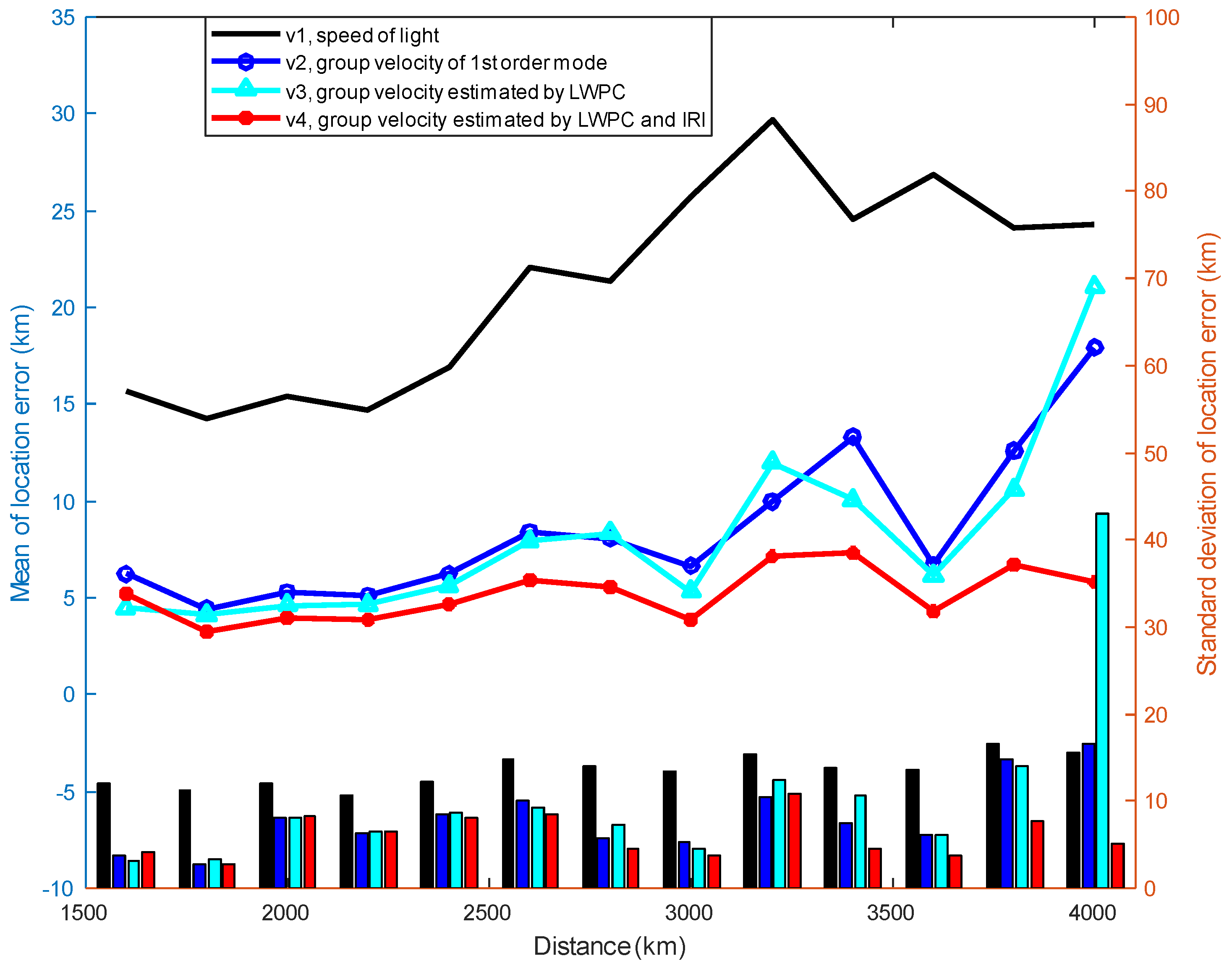
v4 has the best localization accuracy relative to other group velocity estimation methods; on the other hand, the first-order mode group velocity,
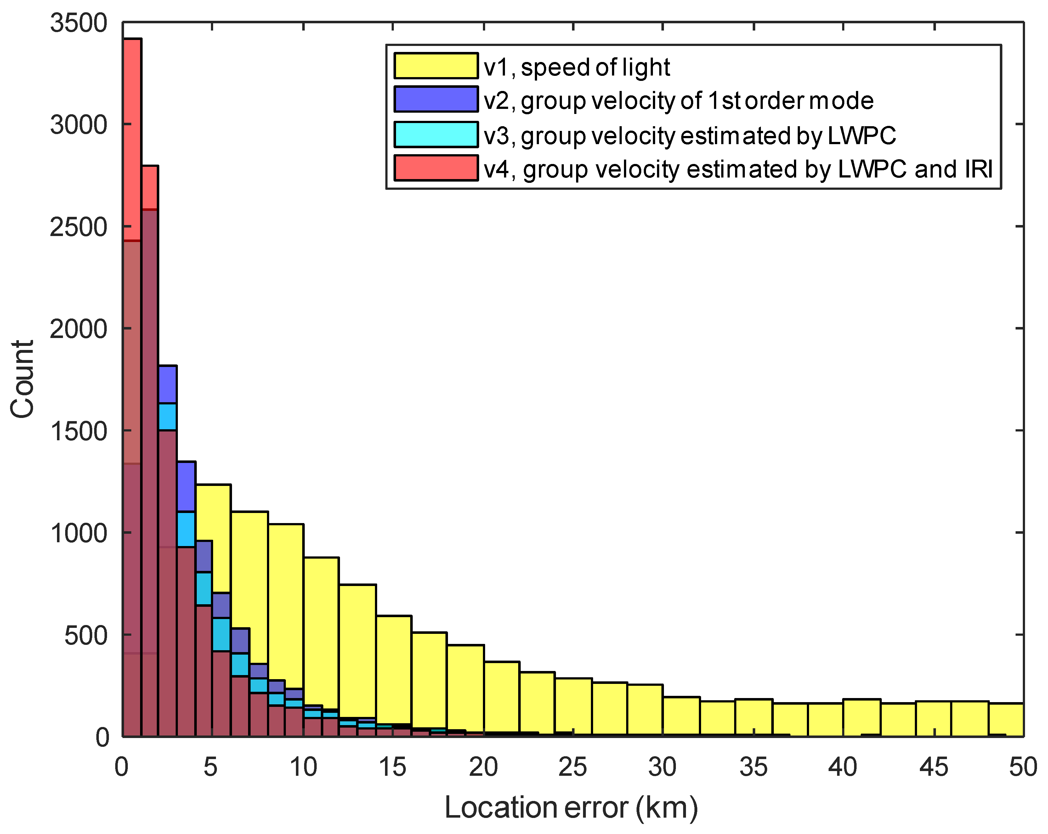
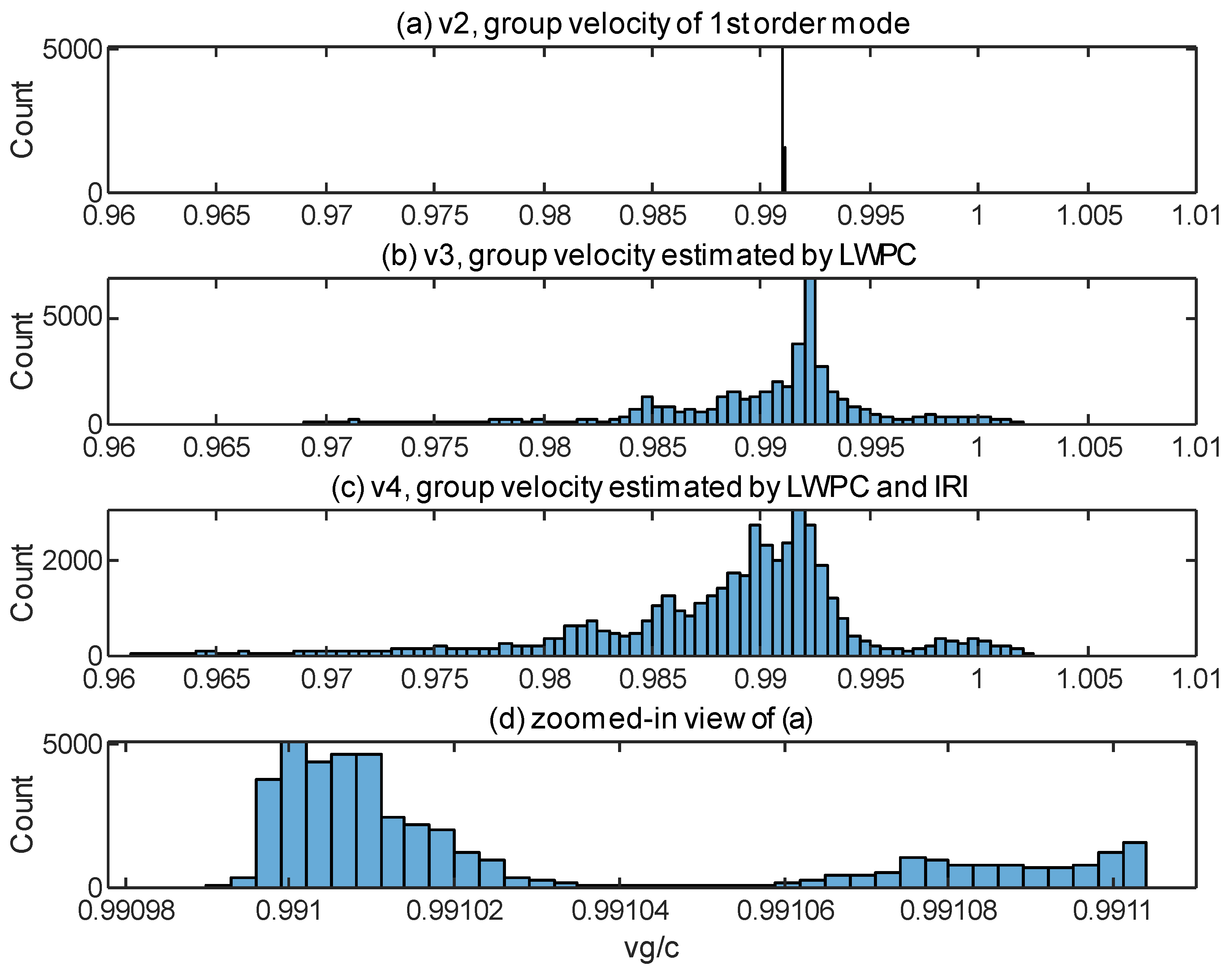
v2, also achieves very high localization accuracy by calculating the equivalent reflection height of the ionosphere on the path using the IRI model, and therefore, it is necessary to analyze the group velocities calculated by different methods of group velocity estimation. We perform a statistical analysis of the group velocities of all lightning events in
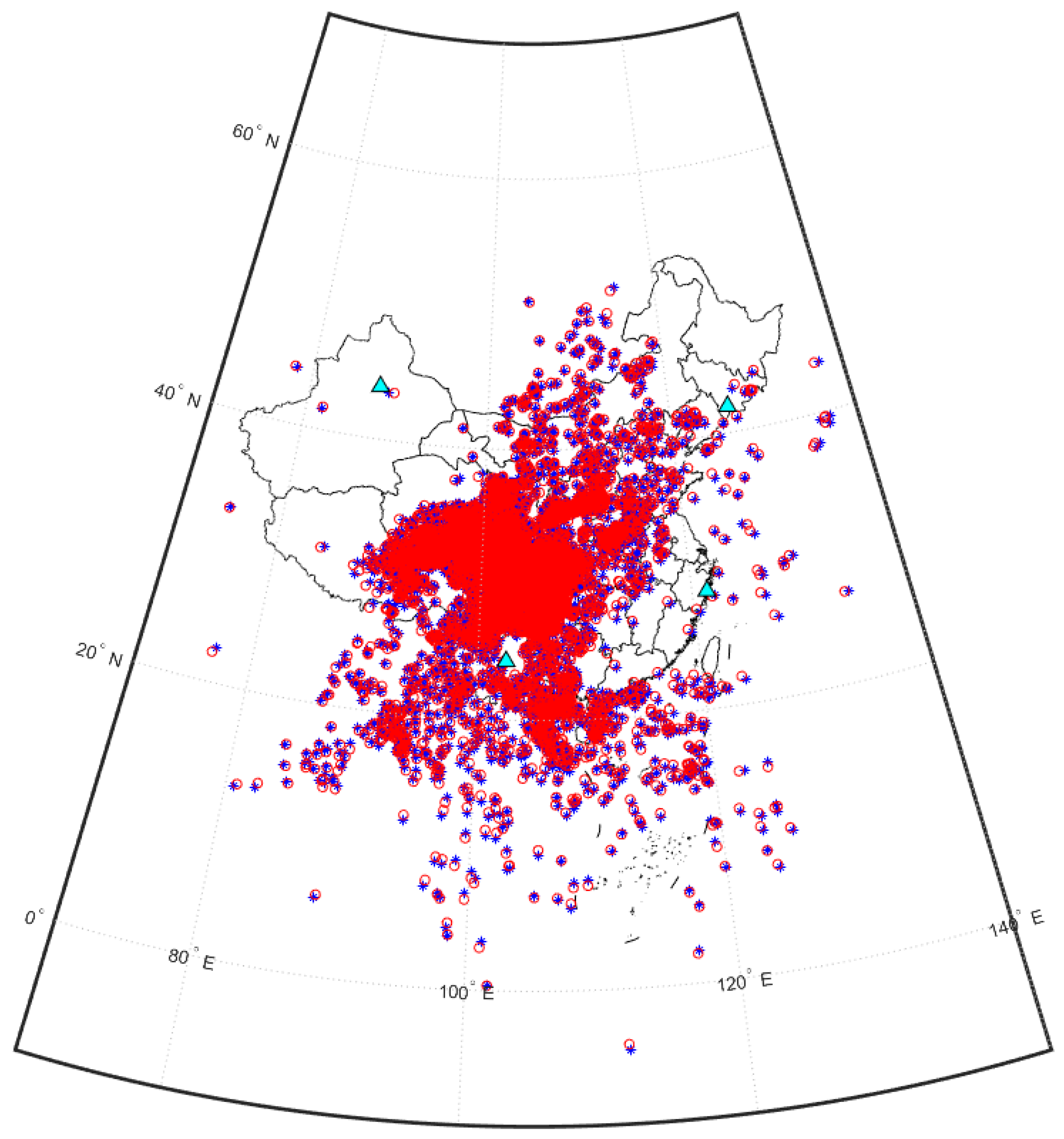
Figure 3, and the histograms of the group velocity distributions are plotted as shown in
Figure 10.
Figure 10a–c show the propagation velocity distribution of
v2,
v3, and
v4, respectively.
Figure 10d is a zoomed-in view of the group velocity distribution in
Figure 10a, and it can be seen that almost all of the group velocity values are concentrated in a very narrow interval around 0.991c.
After the analysis of group velocity distribution in
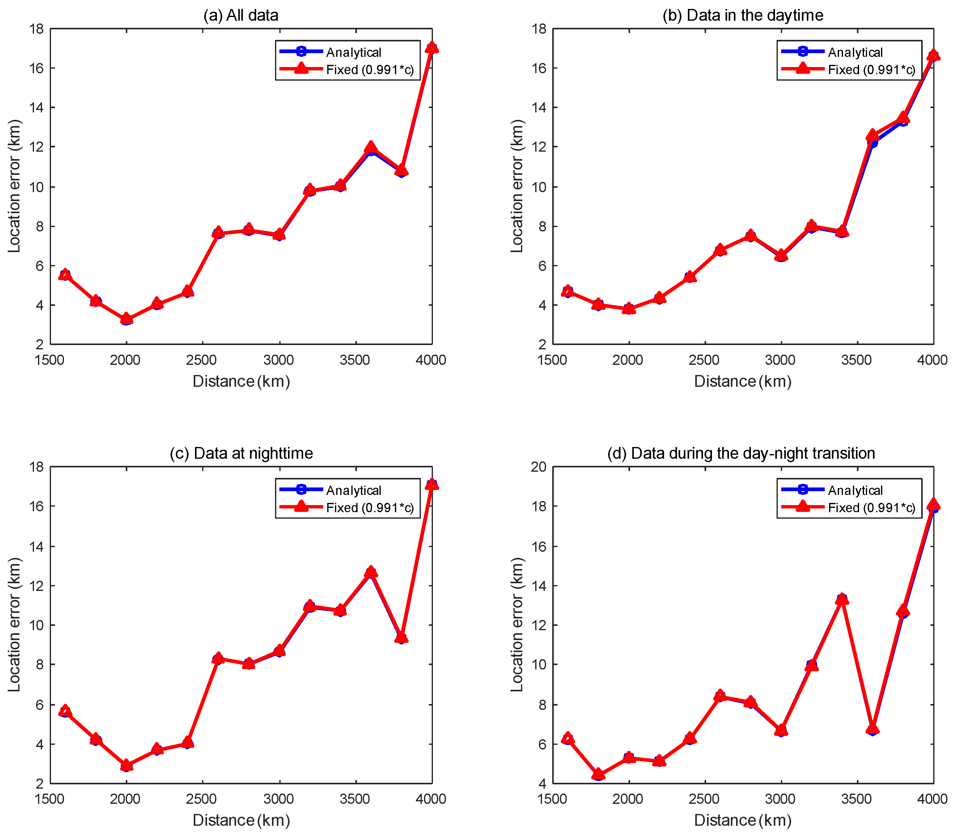
Figure 10 and the localization error in the previous section, a natural question arises: Since the group velocities of the first-order waveguide mode are mostly concentrated around 0.991c and have high localization accuracy, can similar localization accuracy be obtained by directly applying a fixed group velocity of 0.991c to all lightning detection data?
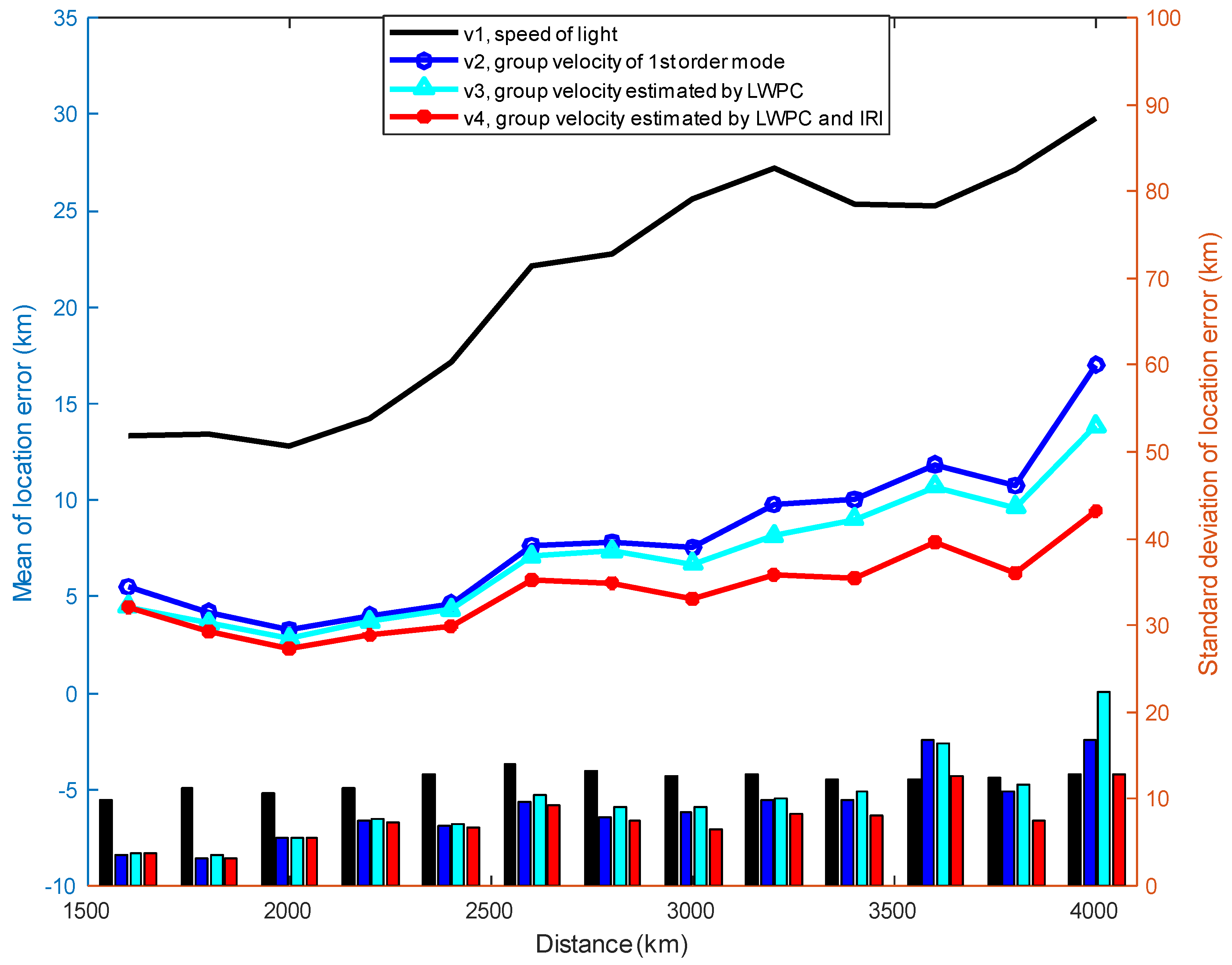
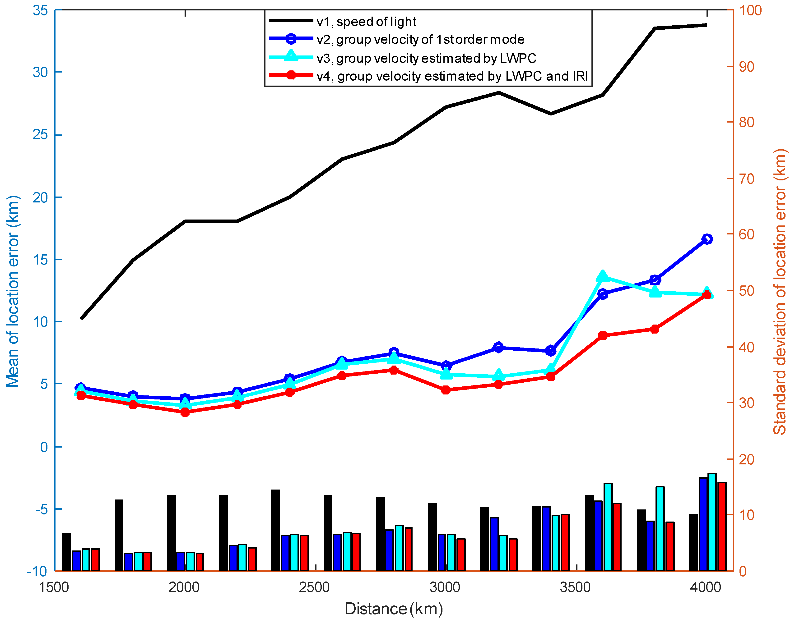
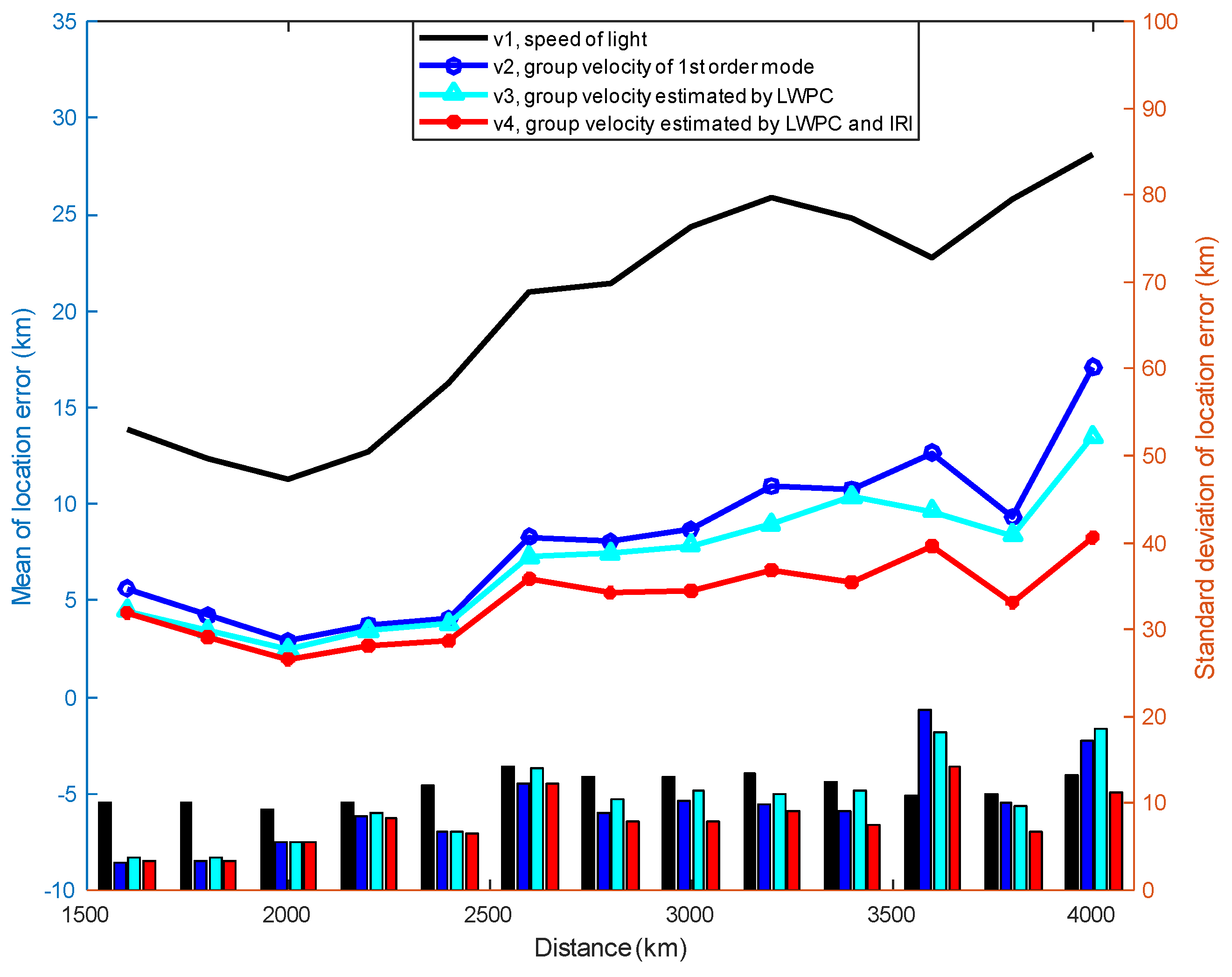
Figure 11 shows the comparison of the localization error curves between the fixed group velocity (0.991c) and the group velocity of the first-order mode.
Figure 11a–d show the comparison of the localization error curves using all data, daytime data, nighttime data and day–night transition data, respectively. As seen in the figure, the fixed group velocity achieves almost the same localization performance as the first-order mode group velocity, while the former does not need to use either the IRI model to calculate the equivalent reflection height of the ionosphere on the path or the LWPC model to calculate the phase of multiple frequency points. In other words, for our experimental detection network and a limited surrounding area, a fixed group velocity can be used to localize the lightning event and obtain a good localization accuracy similar to the first-order mode group velocity.
Nevertheless, we should note that the experimental data used in this paper are located in a very restricted area. When the lightning signal propagates farther and the propagation path is more complex, it is generally difficult to use a certain fixed group velocity to meet the diverse scenarios, and then the group velocity estimation method proposed in this paper can be used to improve the localization accuracy.
