1. Introduction
In the past two decades, unmanned aerial vehicles (UAVs) have been used in many scientific research fields for various applications. Among them, the use of UAVs for magnetic surveys is a booming branch and is expected to be actively applied in the future [
1]. However, the interference that is generated by the aircraft platform may significantly affect the detection performance. Aeromagnetic compensation is designed to solve the problem of magnetic interference generated by aircraft platforms.
Although nonmagnetic materials are used as much as possible in the design, some modules and structures of the UAVs still contain ferromagnetic materials (e.g., engines, motors). Magnetic fields generated by these ferromagnetic materials and the electromagnetic fields generated by the airborne electronic system during operation contribute to the main components of the interference. In fact, this problem also exists in traditional aeromagnetic surveys [
2]. Most research on aeromagnetic compensation has mainly focused on the suppression of the magnetic interference generated by aircraft maneuvers [
3] and the onboard electronic equipment (OBE) [
4].
Given that the aircraft platform affects the accuracy of magnetic measurements, Tolles proposed a classical aeromagnetic compensation model in the 1940s [
5] named the Tolles–Lawson (TL) model. Paul Leliak proposed sinusoidal maneuvers to improve compensation performance in 1961 [
3]. In 1980, B.W. Leach proposed a ridge regression algorithm to solve the aeromagnetic compensation parameters [
6]. Most of the aeromagnetic interference compensation problems can be solved by selecting an appropriate solution method for the TL model. In 2011 and 2013, Gerardo Noriega proved the viability and reliability of using the standard deviation of the signal as an assessment criterion through a large number of aeromagnetic trials [
7,
8]. This evaluation method is also used in this paper. By comparing the improvement ratio (IR) [
7], a more suitable compensation model and calculation method can be selected. The above is a typical framework of aeromagnetic compensation technology progress, which is shown in
Figure 1. Many researchers constantly propose various improvements in improving models and methods in order to obtain higher-quality aeromagnetic data.
In addition to building magnetic interference models based on the principle of interference sources, some researchers also put forward clever methods that are more suitable for engineering applications by using the characteristics of the system. For time-varying interferences with an unknown signature, Sheinker proposed an adaptive magnetic interference cancelation method by using a pair of magnetometers, which obtained good results for highly correlated interference magnetic fields [
9]. Further, based on the signal correlation [
10], Mu et al. established a two-channel linear time-invariant (LTI) model to remove UAV interference. This method is completely different from the traditional compensation flight, and the interference related to the UAV is regarded as a whole rather than several parts related to maneuvers. Adaptive interference cancellation is realized by a pair of magnetometers based on the assumption that the interference signal is irrelevant to the target signal.
In reference [
11], an experiment was designed to add two magnetometers to the body to evaluate the dynamic noise gradient, but it was found that the main factor affecting the dynamic noise of magnetic detection came from the current in the OBE. In [
12], a linear system approach for the mitigation of onboard noise sources by some reference sensors was developed. However, there is no perfect expression of the measurement in the dynamic process of the auxiliary sensor. In [
4], an improved procedure for aeromagnetic compensation is presented, the interferences due to the strobe and beacon lights are modeled to be proportional to the currents flowing through the lights, and the currents are measured by the OBE sensors.
Study [
13] provides a method for finding the position of the OBE switching effect through the first derivative of the magnetic field and then correcting it. This method is easy to implement in stable aeromagnetic data, but it cannot work properly when the magnetic signal changes dramatically during the large-angle maneuver of the platform.
It can be seen that the importance of magnetic interference compensation for OBE on UAVs has been gradually paid attention to. However, in previous studies and experiments, the magnetic interference model could not comprehensively consider the body interference [
9,
10,
11], current sensors were needed to realize the simultaneous compensation of multiple interferences [
4], or the proposed method could only be applied in special smooth flight [
13]. It is challenging to achieve a multi-type aeromagnetic compensation method with higher applicability and accuracy without changing the installation mode of most existing magnetic detection systems.
It can be seen that the magnetic interference compensation for OBE on UAVs has the following limitations:
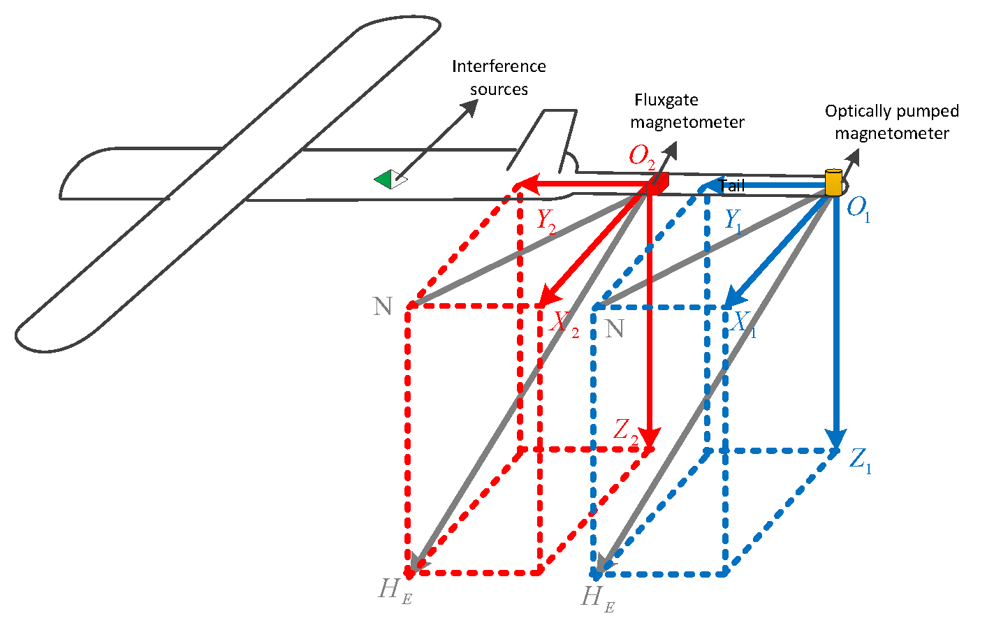
In practice, there are two different magnetometers in the magnetic detection systems. One is a scalar magnetometer, which is far from the aircraft and used to measure the scalar target magnetic signal; the other is a vector magnetometer, which is near the aircraft body and used to obtain the direction cosine of the geomagnetic field in the reference system of airborne platform. Thus, both magnetometers will collect scalar and vector magnetic fields at the same time [
4]. Statistics presented in [
1] show that
of 16 Fixed-Wing UAV cases in recent years used both scalar and vector magnetometers. Each of these cases can directly apply the methods in this article to improve data quality without the need to introduce additional current sensors. It is also suitable for Manned Fixed-Wing Aircraft with similar installation schemes.
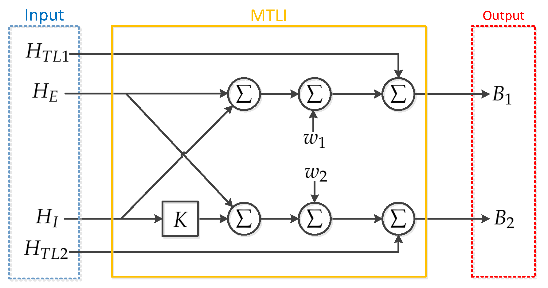
This paper presents a magnetic interference compensation method based on the multi-source two-channel linear time-invariant (MTLI) correlation model. In the proposed method, the magnetic interference can be estimated and compensated for by interference correlation without adding current sensors or changing the structure of most aeromagnetic detection systems. The method is especially effective for canceling a time-varying magnetic interference with an unknown signature, especially the interference originating from OBE that varies unexpectedly with time. In this study, we lay out the theoretical analysis and demonstrate the method using computer simulations. The experiments with real magnetic signals support theoretical and simulation results. The high accuracy and the simple implementation make the proposed method attractive for magnetic surveys.
The paper is organized as follows.
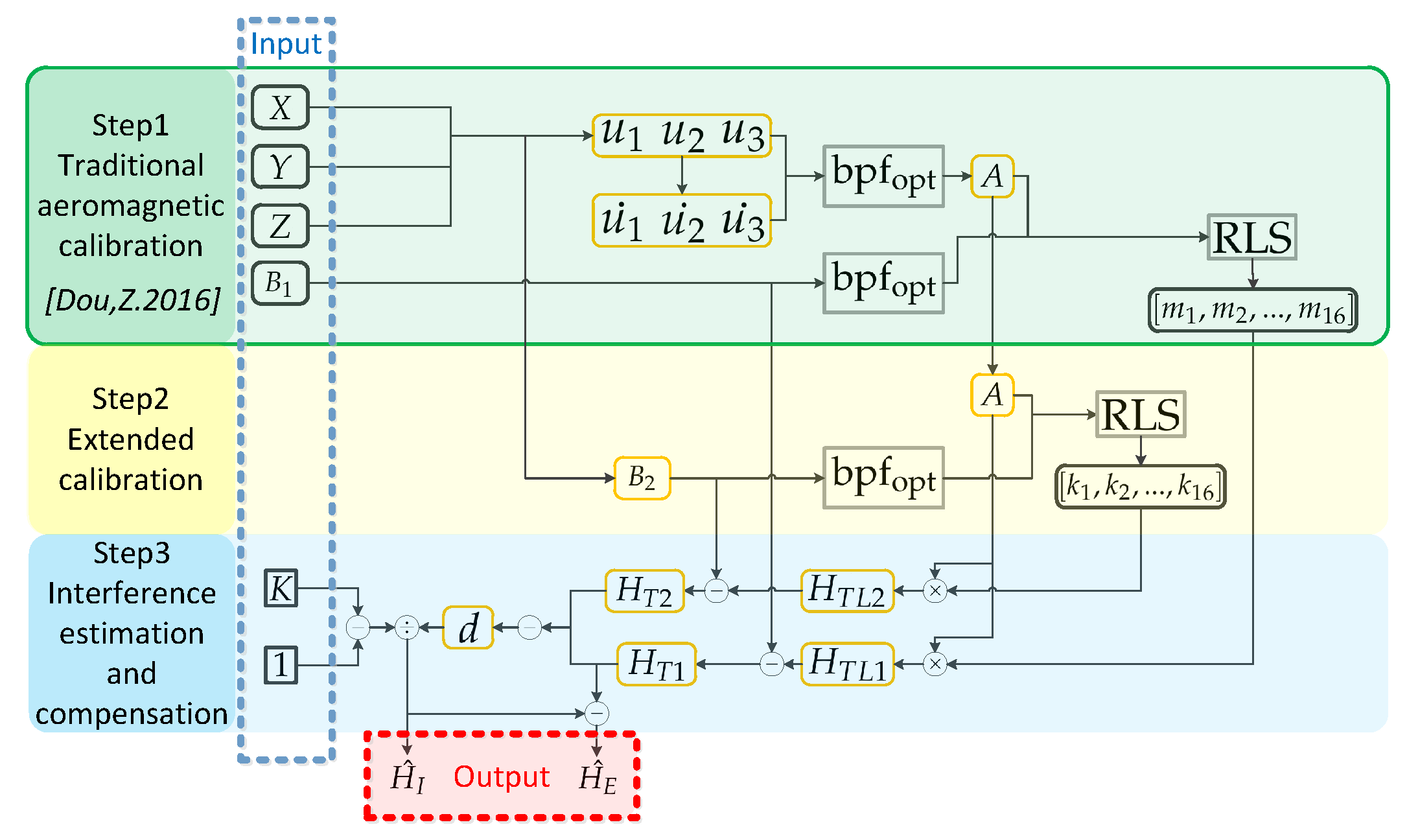
Section 2 presents the configuration of the UAV-magnetometer system and correlation model. The steps for estimating and compensating magnetic interference are also given in this section.
Section 3 analyzes the error of magnetic interference estimation. The numerical analysis and experimental results are discussed in
Section 4 and
Section 5.
Section 6 provides the conclusions of this research.
3. The Error Propagation
The above estimator of
in Formula (
13) is not free from noise, and, in fact, substituting Formula (
1) into (
13) yields
For
, the noise influence is attenuated. Large values of
K can be obtained by deploying the fluxgate much closer to the OBE than the magnetometer. Substituting Formula (
1) into (
14) means we can get the expression for the above estimator’s noise:
Now substituting Formula (
15) into (
16) yields:
Formula (
17) no longer contains the residue of
in the estimated signal
. However,
has been recovered at the expense of an additional noise component from fluxgate. Again, larger values of
K can reduce noise influence.
Now, let us assume zero mean processes, the powers of the signals and noises are expressed by Formula (
18). Here,
is the expectation operator.
3.1. The Error Propagation of
Now we will focus on calculating the error for the interference estimator. Using Formula (
15), the error in estimating
is expressed by
Using the definitions in Formula (
18) and the assumptions that the noise and signals are uncorrelated, we obtain the expression for the estimator’s variance:
We use the ratio of the estimated interference power and the actual interference power to describe the deviation of the estimate.
Here, we define the interference-to-noise ratio
and the noise-to-noise ratio
by
The relative error in estimating
can be expressed as
3.2. The Error Propagation of
Then error analysis is performed on
. The error in estimating the signal in Formula (
14) is expressed using Formula (
17):
Now, calculate the variance of the estimator using
From Formula (
25), the error in estimating
is a function connection with not only the noise at the magnetometer,
, but also the noise at the fluxgate,
. Though the influence of
is
times weaker than
, the interference has been canceled at the expense of additional noise from the fluxgate.
The same as
, we calculate
as follows:
Formula (
22) is used for substitution Formula (
26), and defining the signal-to-noise ratio
:
In the derivation of
and
,
is related to the values of
and
,
also is related to the values of
, and what is more,
is related to
. Both
and
are decreased indefinitely with
K, but
is ultimately bounded by
. From Formula (
27), the error
is not influenced by the
value; this conclusion can be applied to an aeromagnetic compensation process.
In the aeromagnetic compensation process, in order to obtain a more accurate , a high-precision magnetometer is used. Therefore, is usually very small, and the value will be relatively large. In this case, we only need to select a high-precision fluxgate to get a smaller , and we need to appropriately place the fluxgate closer to the interference source to get a bigger K. Then, we can get a smaller . Since is independent of , even if the is small, that is, it is difficult to distinguish the OBE’s interference from the magnetic field to be measured in the magnetometer’s output, the OBE’s interference can be well compensated. The application of this conclusion perfectly avoids the extra monitoring of OBE’s interference and compensates dynamic noise with the lowest cost only by modifying the calculation process.
4. Numerical Analysis
In order to test the proposed method, we have developed a computer simulation implementing the model in Formula (
1) and the estimators in Formulas (
13) and (
14). We use synthesized signals, interference, and noise for the testing, where the signal
and the interference
are generated using monochromatic sinusoidal signals with frequencies of 0.1 and 0.12 Hz, respectively. Frequency signals with very similar frequencies are also used to increase the authenticity of the simulation process. The noise is produced by a random number generator seed using a Gaussian distribution.
We have chosen here to use a window of N = 60,000 samples, which is about 100 min for a sampling rate of 10 samples/s. From a practical point of view, using a long window does not pose a problem since the processing may be performed offline. The longer window is used here to facilitate statistical analysis of the performance of this method. In practical application, this method can also be calculated quickly, point by point. During the simulation, we set and to simulate the real application of magnetic interference that is difficult to peel off the situation.
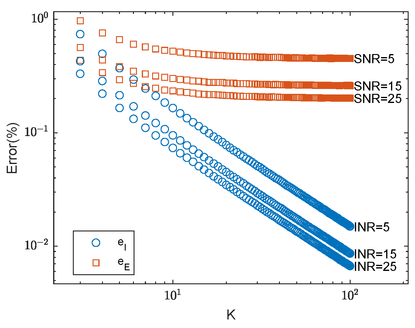
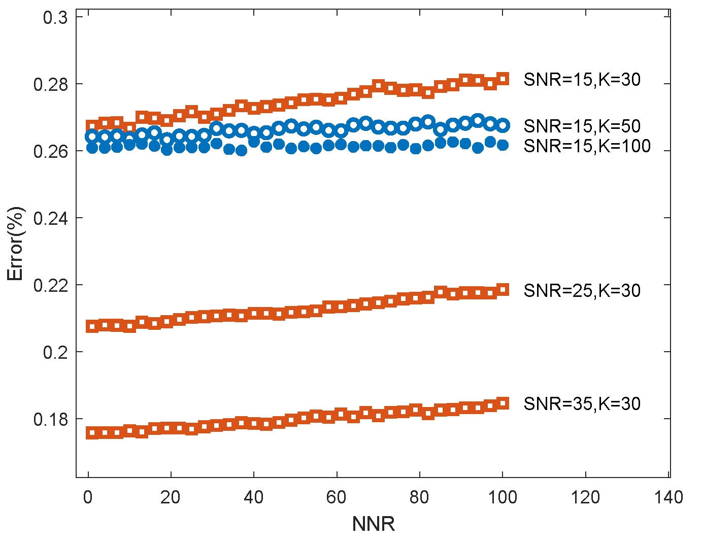
Figure 5 depicts the errors as a function of
K, and, as expected, the errors decrease as a function of
K. Here, we set
to mimic the common fluxgate noise and magnetometer noise. The influence of
K,
, and
on the estimation error was analyzed.
Figure 5 clearly shows that large values of
K enable a better estimation of the interference, which is important for estimating the signal
. Thus, in the case of a known source of interference (such as the steering gear and radio of an aircraft), it is better to place the fluxgate as close as possible to the source of the interference and the magnetometer as far away as possible, provided that the magnetic interference can be regarded as a magnetic dipole. Again, we see in
Figure 6 that the larger
K, the smaller the estimation error
; here we set
.
Figure 6 also shows that when the magnetic field to be measured changes more dramatically; that is, when the
is larger, the estimation of this method will be more accurate.
5. Experiment
5.1. Experiment Design and Sensors
Real flight experiments are carried out in Gansu Province, China, where the geomagnetic background field is magnetically quiet. The experiment was carried out at the end of April 2020 with the purpose of evaluating the performance of the proposed method. The site was prepared by marking off a 20 × 20 km area. The UAV used for this study was a fixed-wing aircraft fitted with a Differential Real-Time Kinematic (D-RTK) system. The RTK approach was used to measure fluctuations in the computed positioning estimates, obtained through the use of Global Navigational Satellite Systems (GNSS), and relaying these to the UAV in real-time to compensate accordingly. Mission planning and autonomous flight control was handled through Universal ground Control Software (UgCS). A GSM19M magnetometer bases tation from Gemsystems was placed near the take-off location of the survey area and used for sampling the geomagnetic diurnal variation.
The UAV has a wingspan of 18 m, and a magnetometer is mounted at the end of the wing. The optically pumped magnetometer with
4He atoms is used for measuring the scalar magnetic field, which is well suited for measuring the geomagnetic field, and its principle can be seen in [
16]. Select sensor specifications of the magnetometer and fluxgate are provided in
Table 1. The OBE-producing magnetic interference is installed in the fuselage, so
. A fluxgate is installed 2.7 m away from the fuselage, which means
,
. All data are synchronized by the pulse per second signal with a sampling frequency of 10 Hz.
The experiments were carried out according to aeromagnetic compensation standards; we let the platform perform roll, pitch, and yaw maneuvers in the four directions of east, south, west, and north in a fixed period of about 8–12 s. The flying altitude was more than 3000 m, which was high enough to avoid the magnetic interference caused by the local geology. Flight tracks are shown in
Figure 7a, in which the maneuvering flight and smooth flight tracks are basically the same.
5.2. Data Processing
Standard processing steps were applied to the magnetic dataset: (i) Timestamping and positioning; (ii) Despiking of erroneous GNSS; (iii) Removal of diurnal variation as monitored by a base station.
Figure 7b,c show the original magnetic field and the compensated magnetic field measured in the maneuvering flight and smooth flight. The aeromagnetic data are well compensated by the method proposed in this paper.
5.3. Experiment Results on Fluxgate
Since the OBE is closer to the fluxgate (), the effect of compensation for the OBE’s interference can be observed more intuitively and significantly on the fluxgate. We show the results of the fluxgate’s magnetic field value before and after compensation during a period of roll maneuvering.
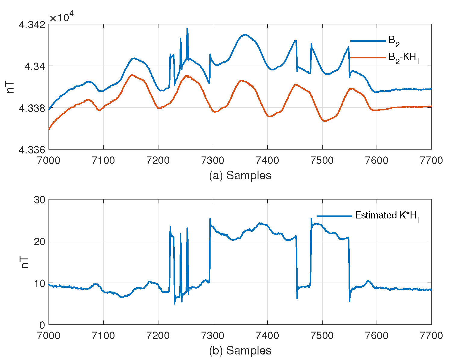
The blue line in
Figure 8a is the magnetic field synthesized by the fluxgate. It can be seen that since the fluxgate is close to the aircraft, the dynamic magnetic interference caused by the switch of electrical equipment can be obviously observed in a “gate” shape with a size of about 15–20 nT, and its occurrence time is irregular.
Figure 8b shows the OBE’s magnetic interference at the fluxgate position estimated from Formula (
13). When the OBE’s magnetic interference is removed from
, the result is the red line in
Figure 8a. The fluxgate output is obviously smooth after removing the OBE’s magnetic interference, and the magnetic interference caused by maneuvering action is retained.
5.4. Experiment Results on Magnetometer
The ultimate goal of removing the OBE’s magnetic interference is to make the magnetometer’s output cleaner. Therefore, this section shows the compensation effect of the magnetometer output.
We compared this method with those in [
10,
14]. It should be noted that the formula used to calculate
k in [
10] is based on the input of similar precision sensors, while the accuracy of
in the widely used aeromagnetic compensation system involved in this paper is much higher than that of
. Therefore, the calculation of its
k in [
10] is calculated by Formula (
10) in this paper, and the method is cited as Mu,Y. 2020-M. In addition to directly observing the signal, the standard deviation(
) in reference [
7] is used to evaluate the system noise. The smaller the
is, the smaller the dynamic noise of the system is.
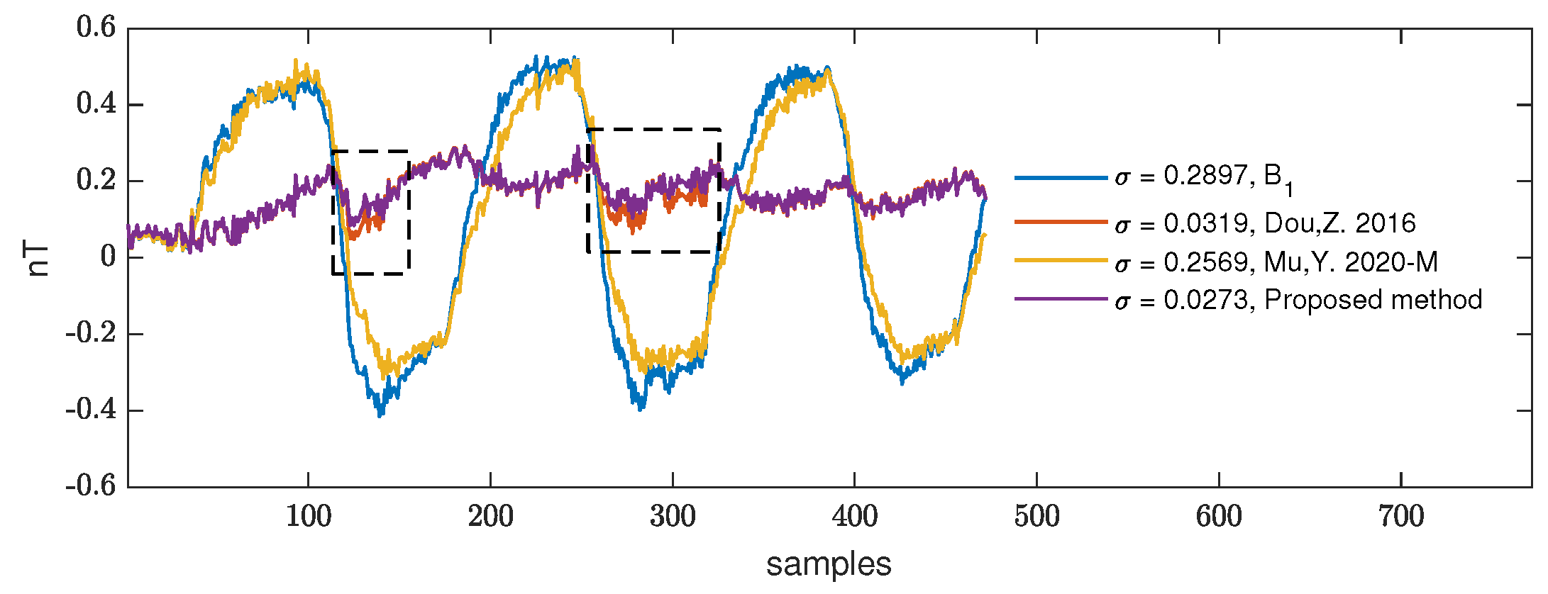
First, we compare the performance of the three methods in the maneuvering process. In
Figure 9, the blue line represents the original signal, which is
, the red line is the calibration and compensation method mentioned in reference [
14], and the yellow line represents the compensation result of Mu,Y. 2020-M. The purple line is the result of the method in this paper. The dotted-box part is the obvious repair process of this kind of magnetic interference. The method Mu,Y. 2020-M cannot provide good results in maneuvering because it does not consider the interference of the body itself in its system. However, the results are close to the method proposed in this paper in smooth flight. The method in this paper can accurately compensate for the OBE’s magnetic interference in addition to the magnetic interference caused by maneuvering. The purple line in
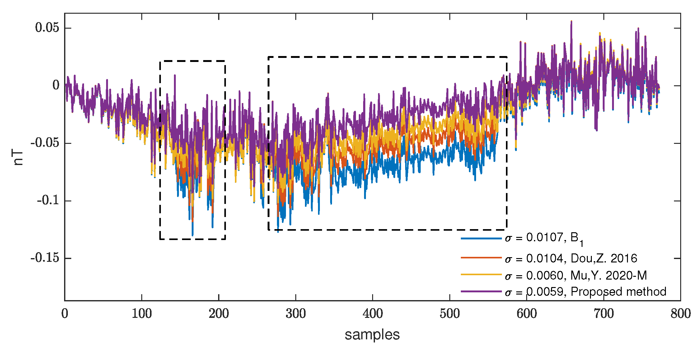
Figure 9 and
Figure 10 are part of the data in
Figure 7, which have been aligned and detrended to facilitate the observation of the compensation effect of magnetic interference.
The results combined with the standard deviation
of the three methods in smooth flight data are shown in
Figure 10. The method proposed in this paper can accurately compensate the OBE’s magnetic interference in the maneuver and also performs well in the smooth flight.
The above results show the effect of the local data when the OBE’s magnetic interference occurs. Since the occurrence is random, in order to evaluate the performance of the proposed method in the long-duration flight data, we used the same evaluation method to evaluate the flight data in different directions. The flight duration in each direction is not less than 5 min.
Table 2 shows the effect of the proposed method on maneuvering flight and smooth flight. The values in the table are the standard deviations
of data in a certain direction, where the lower, the better. Columns 1–4 represent the maneuvering flight of the aircraft in different directions. Columns 5–8 represent the smooth flight of the aircraft in different directions. The proposed method can perform well under different flight conditions. The
of maneuver data in different directions is obviously larger than that of smooth flight data. This is because maneuvering involves rolling, pitching, and yawing. In Method Mu,Y. 2020-M, the
after compensation is close to or even greater than the raw data because the magnetic influence brought by aircraft maneuvers is not considered.
More importantly, this method does not introduce other noises in the process of OBE’s interference without switch, can accurately compensate for all noises caused by this type, and does not need an additional recognition algorithm to avoid the robustness problem caused by recognition accuracy.

