Communication

Inverse Synthetic Aperture LiDAR Imaging of Rough Targets under Small Rotation Angles

1
School of Physics and Optoelectronic Engineering, Xidian University, Xi’an 710071, China
2
School of Electronic Engineering, Xidian University, Xi’an 710071, China
*
Author to whom correspondence should be addressed.
Remote Sens. 2022, 14(11), 2694; https://doi.org/10.3390/rs14112694
Submission received: 19 May 2022 / Revised: 1 June 2022 / Accepted: 1 June 2022 / Published: 3 June 2022

Abstract

:
Inverse synthetic aperture LiDAR (ISAL) breaks through the limitations of the diffraction limit and achieves ultra-long-distance radar imaging with centimeter-level resolution. However, because ISAL obtains a high resolution, it is accompanied by a high sampling rate and a large data volume, and the processing process is complicated, which is not conducive to fast real-time imaging of ISAL targets. At the same time, considering that actual non-cooperative targets cannot obtain full-angle ISAL images during movement, in this paper, the Kirchhoff approximation method based on two-dimensional Fourier transform is used to calculate the scattering echo of the rough surface of the target, and then, the rough surface scattering echo of the target coordinate system is obtained through coordinate transformation. After vector superposition, the scattered echo and ISAL image of the rough target are finally obtained, and then the influence of the rotation angle on the ISAL imaging of the rough plate and the rough target is discussed. It is found that a small rotation angle range can also achieve clear ISAL imaging of rough targets, and the influence of different roughness on the ISAL imaging results of different rough targets under a small rotation angle is analyzed. When the roughness is decreased, the target scattering mainly comes from coherent scattering, and the target edge becomes sharper. As the roughness increases, the image energy distribution becomes more uniform. Theoretical and simulation experiments verify the feasibility of ISAL imaging of rough targets under small rotation angles.

Graphical Abstract

1. Introduction

Inverse synthetic aperture LiDAR (ISAL) is an active imaging radar. It is a product of the combination of synthetic aperture technology and LiDAR technology. It has an extremely high imaging resolution, is independent of the detection distance, and achieves high-resolution detection of long-range targets. Synthetic aperture radar uses motion to simulate virtual aperture synthesis to achieve two-dimensional, high-resolution imaging [1,2]. Traditional inverse synthetic aperture radar (ISAR) based on a discrete fractional Fourier transform [3,4] and two-dimensional searching [5] can be used to obtain a scattered echo. Compared with microwave and radio radar, LiDAR has a high frequency and short wavelength due to its high degree of remote-sensing detection and spatial resolution. It has unique advantages in terms of continuous monitoring in terms of time and measurement accuracy [6,7,8].
In 1992, B. Borden [9] applied the method of maximum entropy to the regularization of inverse synthetic aperture radar (ISAR) image reconstructions. This was accomplished by considering an ensemble of images with associated “allowed” probability density functions. The basic model of this approach is similar to that used in usual maximum a posteriori analyses and allows for a more general relationship between the image and its “configuration entropy” than is usually employed. In addition, it eliminates the need for inappropriate non-negativity constraints on the (generally complex-valued) image. In 2012, Caner Ozdemir [10] gave detailed imaging procedures for ISAR imaging with associated MATLAB functions and codes. To enhance the image quality in ISAR imaging, several imaging tricks and fine-tuning procedures, such as zero-padding and windowing, were also presented. In 2014, V.C. Chen and M. Martorella [11] introduced several important autofocus algorithms for ISAR image formation, including the phase gradient autofocus algorithm, the image contrast-based autofocus algorithm, and the entropy-minimization-based autofocus algorithm. In 2016, Yong Wang [12] proposed a novel algorithm for the analysis of SFM signals based on adaptive chirplet decomposition, which was accurate, efficient, and easy to implement. In 2018, Lu Yakun [13] proposed an imaging algorithm based on the integral cubic phase function-fractional Fourier transform, which eliminates distance dispersion and solves the problem of image defocusing caused by time-varying azimuth Doppler caused by maneuvering. In 2018, Liu Shengjie [14] and others proposed a joint compensation imaging algorithm based on the Nelder–Mead simplex method and the quasi-Newton method, which accurately estimated the motion parameters of a target and obtained a well-focused, high-resolution, two-dimensional ISAL image. In 2019, Min-Seok Kang [15] proposed a novel approach for CS-SAR imaging based on improved Tikhonov regularization (ITR), coupled with an adaptive strategy using an iteratively reweighted matrix to solve the CS reconstruction problem of SAR images with sparsity. The proposed scheme outperformed conventional CS-based methods with respect to image quality, noise robustness, and computational complexity of the algorithm, due to the additional sensitivity of the proposed objective function. In 2019, Chen Hanling [16] proposed the use of a high-sensitivity, coherent, balanced detection to realize the long-distance detection of ISAL in space and calculated the signal-to-noise ratio of ISAL-balanced detection to solve the problem of insufficient long-range detection sensitivity. In 2020, Tian He [17] proposed a sparse imaging algorithm for micro-moving targets, based on spatial domain compressed sensing, to realize micro-moving target image reconstruction. In 2021, Li Jian [18] proposed a global joint motion error compensation algorithm based on the Nelder–Mead simplex method and particle swarm optimization on the basis of a high-precision imaging model. In 2022, Yang Xiaoyou [19] used the motion compensation method, based on the reference point, and achieved an accurate estimation of the trajectory of a motion reference point through an envelope alignment after matched filter processing and realized ultra-high-resolution 2D imaging of a moving target. In 2022, Hongfei Yin [20] proposed a varying amplitude vibration phase-suppression algorithm. Working without prior knowledge, the proposed algorithm can suppress paired echoes under the condition of varying vibration amplitude and does not introduce new phase errors. Furthermore, the method is suitable for an imaging scene without isolated points. Both the simulated and real experiment results of the ISAL turntable data demonstrated the effectiveness of the proposed algorithm.
Due to the high frequency of the laser itself, an ISAL image of a larger rough target will be accompanied by a high sampling rate and data redundancy, resulting in a complicated calculation process and an excessive amount of computation, which cannot meet the demands of fast imaging. At the same time, considering the difficulty of full-angle imaging in the actual movement of non-cooperative objects, this article combines actual needs based on the ISAL imaging principle and uses the Kirchhoff approximation method based on two-dimensional Fourier transform to calculate the scattered echo of a rough target surface. It then uses coordinate transformation to obtain the rough surface of the target coordinate system and the scattered echo. After vector superposition, the scattering echo and ISAL image of the rough target are obtained, and the influence of the rotation angle on the ISAL imaging of the rough plate and the rough target is explored. The theory and simulation experiments prove the feasibility of ISAL imaging of rough targets under a small rotation angle and analyze the influence of different roughness on the ISAL imaging results of different rough targets under a small rotation angle.

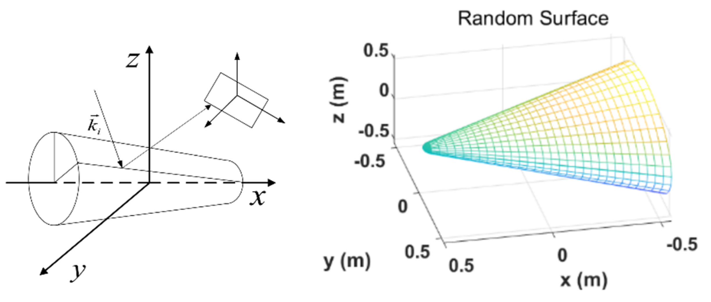
2. Geometric Modeling and Theoretical Formula Derivation

Kirchhoff approximation is also called tangent plane approximation, which is the field strength at any point on the interface and is determined by the tangent plane reflection wave at that point. The rough surface is replaced by a local tangent plane, and the Fresnel reflection law is used to obtain the total field of the tangent plane so as to approximate the scattered field in the far area. Kirchhoff approximation is used to calculate the scattered echo of the target rough surface element [21,22].
E p q s = K 0 E 0 U ¯ p q E X d s
E X = exp i k 1 k ^ s k ^ i r = exp i q x x + q y y + q z z
U ¯ p q x , y = a 0 + a 1 Z x + a 2 Z y
where K 0 = i k 1 4 π R 0 exp i k 1 R 0 . R 0 is the distance between the center of the exposure surface and the observation point. Subscripts p and q represent the polarization states of the incident wave and the scattered wave, respectively; k 1 = 2 π / λ is the wave number, and λ is the wavelength. E 0 is the amplitude of the incident light wave, and this paper takes unit amplitude E 0 = 1 . a i i = 0 , 1 , 2 is the polarization coefficient [22], and Z x and Z y are the slope directions of the expressed height fluctuations.
Using Kirchhoff’s approximation based on the two-dimensional Fourier transform to calculate the scattered echo of the target scattering surface element, and substituting Equations (6) and (7) into Equation (5), and then Equations (2)–(5) into Equation (1), the scattering field equation (Equation (8)) of the rough target surface element is determined [23]:
q x = k 1 sin θ s cos ϕ s sin θ i cos ϕ i q y = k 1 sin θ s sin ϕ s sin θ i sin ϕ i q z = k 1 cos θ s + cos θ i q = q x 2 + q y 2 + q z 2
F q x m , q y n = m = M / 2 + 1 M / 2 n = N / 2 + 1 N / 2 f x m , y n exp i q x m x m + q y n y n
f x m , y n = U ¯ p q x m , y n w x m , y n exp i q z z m
w x m , y n = 1 2 π σ 2 exp x m 2 + y n 2 2 σ 2
E p q s = K 0 E 0 Δ x m Δ y n q / q z F q x m , q y n
As shown in Figure 1, θ i , θ s are the incident angle and scattering angle of the rough target, respectively; ϕ i , ϕ s are the incident azimuth and scattering azimuth of the rough target, respectively; after coordinate transformation, θ i , θ s are the incident angle and scattering angle of the rough target surface element, respectively; and ϕ i , ϕ s are the incident azimuth angle and scattering angle of the rough target surface element, respectively.
Here, x m , y m , z m is the three-dimensional discrete coordinates of the rough target; w x m , y n is the kernel function of the two-dimensional discrete Gabor transform, which is used to weaken the edge effect and enhance the image features of the edge; and σ is the width of the Gaussian window, which is the same width as the rough target in this paper.
The scattering field of the rough surface of the target coordinate system is obtained via coordinate transformation, and the total scattering field is obtained by vector superposition.
E s = E p q S
We used fast Fourier transform (FFT) to calculate the scattered field of the rough target [23]. Because the FFT algorithm itself is discrete and an improvement of the Fourier algorithm, the principle is the same, but the computational complexity and computational efficiency are significantly improved, and as the number of calculations increases, the computational efficiency will also increase.
Assuming that the radar works in a single-station mode and only accepts electromagnetic waves in the direction of single polarization, the above equation is changed from a vector equation to a scalar equation. Further assuming that the relative motions of the radar and the target meet the rotary table model, Equation (9) can be simplified as follows [24]:
E s / exp i k 0 R 0 R 0 = G K , ϕ = y min y max x min x max g x , y exp i K x cos ϕ + y sin ϕ d x d y
where G K , ϕ is the frequency domain echo of the target, g x , y represents the radar images, K = 2 k 0 is the two-way wave number, and ϕ is the rotation azimuth angle in the target coordinate system. According to the inverse transformation of integral similarity, the double integral formula of the reconstructed target image can be written as:
g x , y = ϕ min ϕ max K min K max G K , ϕ K exp i K x cos ϕ + y sin ϕ d K d ϕ

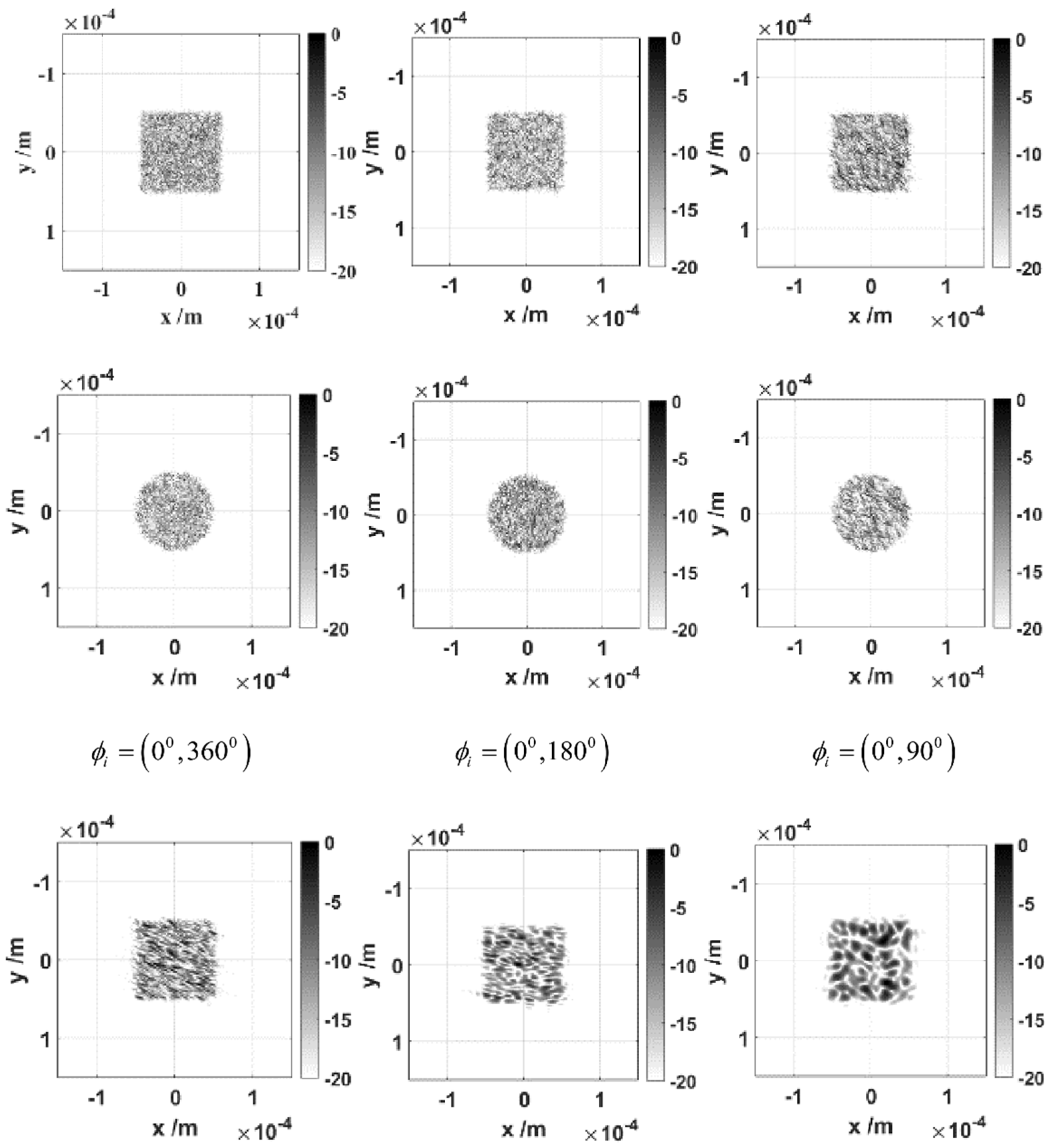
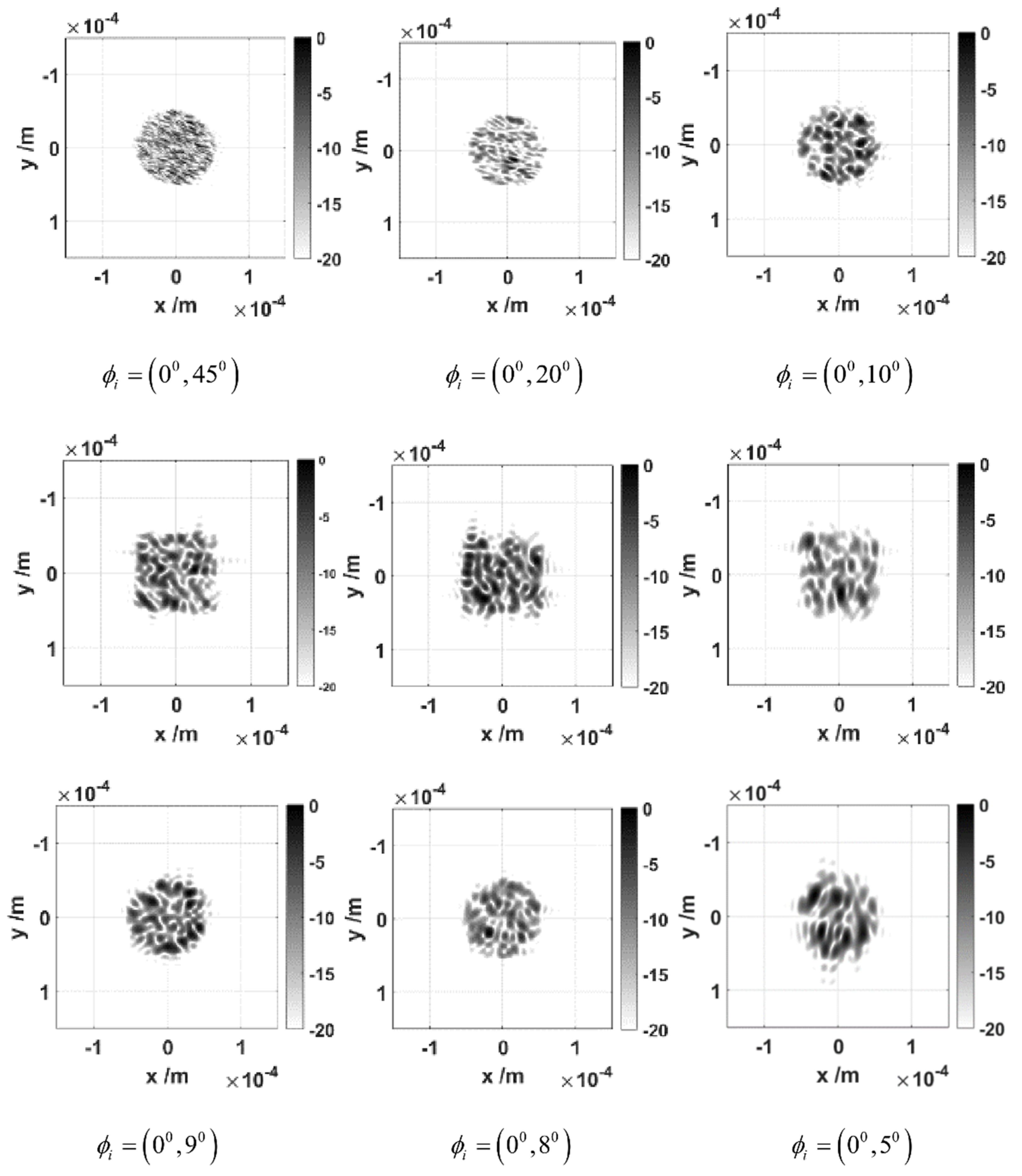
3. Rotation Angle Imaging of Rough Plane and Targets

ISAL imaging of a rough square plate and a rough circular plate was simulated. The circular plate and square plate model parameters were as follows: the surface material was aluminum, the central frequency of the incident wave was 193.46 THz, and the corresponding wavelength was 1.55 μm. The complex refractive index of aluminum at this wavelength was 1.5785 + 15.685i, and the relative dielectric constant was (–242.68, 49.5) [25]. VV polarization was adopted, the frequency band width was 30 THz, the frequency sampling point was 16, and the unit interval of the rotation angle was 0.1°. The root mean square height was 0.25λ, the correlation length was λ, and the observation angle was 30°. The ISAL imaging results of the rough square plate and the rough disk under different rotation angle ranges were observed. The simulation scale of the rough square plate was 64λ × 64λ; the simulation scale of the rough circular plate was 32λ × 32λ.
As shown in Figure 2, through analysis of the ISAL imaging results of the rough square plate and the rough circular plate with different rotation angles, with a reduction in the rotation angle range, the basic shape of the rough square plate and the rough circ-lar plate did not change; however, the surface granularity of the rough square plate and the rough circular plate was reduced. The imaging effect was better with a rotation angle of about 10°. When the rotation angle was smaller, the noise was greater, and the image quality was poor. Therefore, we speculated that the rough target should be around 10° to present a clear and complete ISAL image.
ISAL imaging of a simulated rough cone was performed. The height of the cone was 1.2 cm, and the radius was 0.24 cm. The surface material was aluminum, the center frequency of the incident wave was 1.9346 × 10¹⁴ Hz, and the corresponding wavelength was 1.55 μm. The complex refractive index of aluminum at this wavelength was 1.5785 + 15.685i, and the relative dielectric constant was (−242.68, 49.5); the VV pole was used. The frequency bandwidth was 0.3 THz, the sampling point of the frequency was 16, and the unit angle interval of the rotation angle was 0.05°. The root mean square height was 0.3λ, the correlation length was λ, and the observation angle was 30°. The ISAL imaging results of cones under different rotation angle ranges were observed.
Through analysis of the imaging results of the rough cone ISAL with different rotation angles, the results of the rough target (cone) and the rough flat plate were basically the same. Among them, the rough cone has a better imaging effect at around 10°, and the basic target shape could be reflected. At the same time, due to the symmetry, we chose to image around the cone tip attachment at 10° (the azimuth angle of the cone tip is 180°), and there is no strong scattering phenomenon of only the cone surface, as shown in Figure 3. Therefore, for the rough target, we selected a small rotation angle centered on the symmetry axis according to the symmetry, and a clear and complete ISAL image of the rough target could be achieved.
On the basis of the ISAL imaging of rough square plate, rough circular plate, and rough cone, under the same conditions, the ISAL imaging time of the rough square plate, rough circular plate, and rough cone was observed under different rotation azimuth angles.
The comparison results are shown in Table 1, which proves that, under the same simulation conditions, as the rotation azimuth angle decreases, the amount of information of the scattered echo decreases, and the time for ISAL imaging decreases as well. Although the imaging time of the rough cone ISAL images at small angles was shortened to less than 30 s, there was still a gap in real-time imaging. Due to the high operating frequency of the laser and large number of surface elements of the rough target, the amount of calculation was significant, and the time could not be shortened to achieve real-time imaging, which is a shortcoming of this method. However, this method significantly improves the computational efficiency on the premise of recognizing the shape of a target and provides a theoretical basis for real-time ISAL imaging of rough targets.

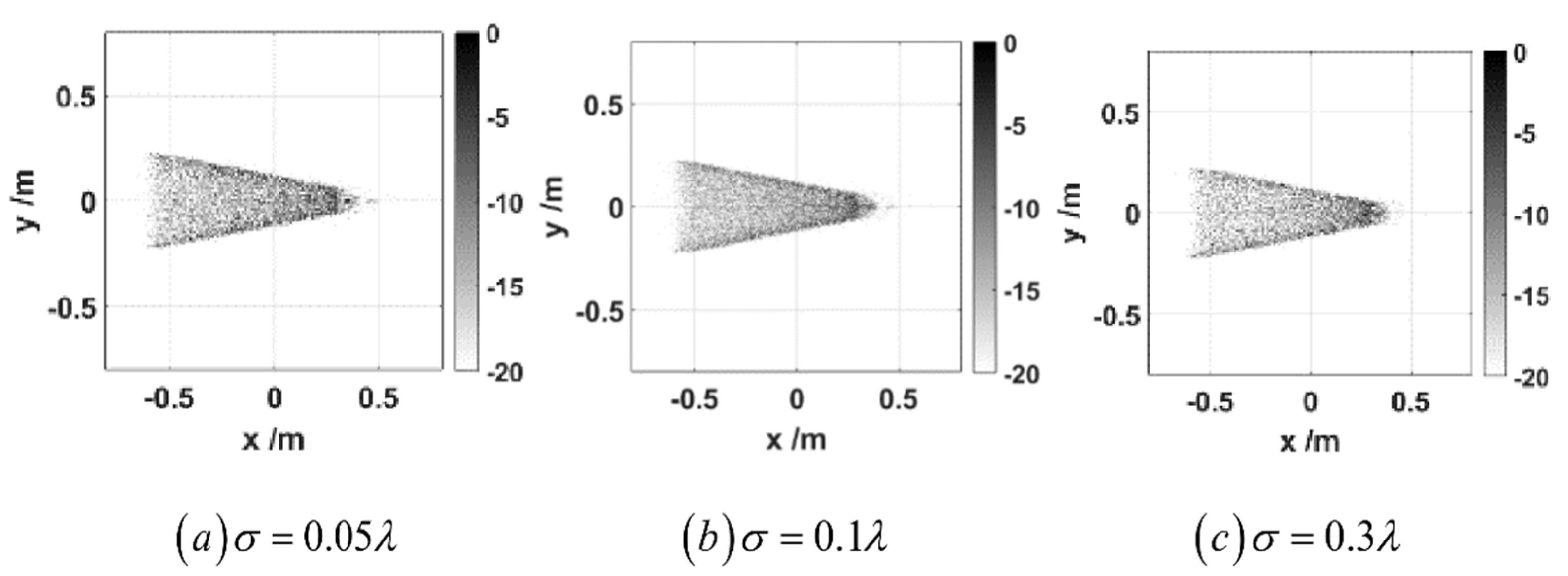
4. ISAL Image of Blunt-Nosed Cones and Double Cones under a Small Rotation Angle

ISAL imaging of blunt-nosed cones with different roughnesses was simulated. The simulation scale of blunt-nosed cones was: height of the blunt-nosed cone was 1.1 m; the radius was 22 cm and 5.5 cm, respectively; the surface material was aluminum; the center frequency of the incident wave was   1.9346 × 10 14   Hz ; and the corresponding wavelength was   55   μ m . At this wavelength, the complex refractive index of aluminum was 1.5785 + 15.658 i , the relative permittivity was 242.68 ,   49.5 , and VV polarization was used. The frequency bandwidth was 3 × 10 9   Hz , the sampling point of the frequency was 16, the range of the rotation angle was 175 0 , 185 0 , the unit angle interval of the rotation angle was 0.00008 0 , and the number of sampling points of the rotation angle was 125,000. The incident angle was 30°, and the correlation length was 1.55 μm.
The ISAL imaging in Figure 4 can clearly distinguish the shape of the blunt-nosed cone, which proves that ISAL imaging can clearly distinguish the shape of the rough blunt-nosed cone at a small rotation angle (10°). When the root mean square height was increased and the surface of the blunt-nosed cone was rougher, the scattering components mainly came from incoherent scattering, and the imaging effect of the blunt-nosed cone was more uniform.
ISAL imaging of double cones with different roughnesses and rotation angles was simulated, and the simulation scale of the double cone was: the height of the double cone was 1.34 m, the radius of the bottom surface of the double cone was 0.27 m, the surface material was aluminum, the center frequency of the incident wave was 1.9346 × 10¹⁴ Hz, and the corresponding wavelength was 1.55 μm. At this wavelength, the complex refractive index of aluminum was 1.5785 + 15.658i, the relative permittivity was (−242.68, 49.5), and VV polarization was used. The frequency bandwidth was 3 × 10⁹ Hz, the sampling point of the frequency was 16, the range of the rotation angle was (175°, 185°) and (265°, 275°), the unit angle interval of the rotation angle was 0.00008°, and the number of sampling points of the rotation angle was 75,000. The incident angle was 30°, and the correlation length was 1.55 μm.
The ISAL imaging in Figure 5 clearly shows the shape of the double cone, which proves that ISAL imaging can clearly distinguish the rough double cone at different rotation angle ranges (under different symmetry axes) at a small rotation angle (10°). This is also different from the ISAL imaging of the blunt-nosed cones. For any rough target, the selected angle range can be different depending on the symmetry axis, but a clear ISAL image with a small rotation angle can be achieved. As the root mean square height decreases, the surface of the double cone becomes smoother, and the scattering distribution mainly comes from coherent scattering, concentrated at the edge of the double cone, so the edge of the double cone becomes brighter.

5. Conclusions

For inverse synthetic aperture LiDAR imaging, full-angle imaging is impossible considering actual situations. Through theoretical analysis and simulation calculation results, it was found that rotating a small angle can also achieve ISAL imaging of rough targets while simultaneously improving imaging efficiency, as well as providing a basis for target rotation imaging. This paper is based on the two-dimensional Fourier transform for calculating the Kirchhoff approximation of the scattering echo method; the scattered echo of the rough plate and the rough target are obtained, respectively; then, the inverse synthetic aperture LiDAR (ISAL) imaging of different rough targets is obtained.
This paper verifies the feasibility of ISAL imaging of rough targets under small rotation angles from theoretical and simulation analyses. First, the influence of different rotation angles on the ISAL imaging results of rough flat plates (square and round plates) was explored. As the rotation angle becomes smaller, the granularity of the rough flat surface decreases, but the basic shape of the rough flat plate can still be clearly seen. The best effect is around a 10° rotation angle (small angle). When the rotation angle is reduced, the noise is greater, and the image quality is poor. Therefore, we speculate that the rough target should be around 10° to show a clear and complete ISAL image. Then, the simulation verifies that the rough target (cone) can present a clear and complete ISAL image at a small angle (10°). Due to symmetry, the rough target should select a small rotation angle centered on the symmetry axis for imaging so that only part of the ISAL image of the target will not appear. Then, the small rotation angle is analyzed under different roughnesses for different target (blunt-nosed cones and double cone ISAL) imaging; when the root mean square height is increased, the rough target (blunt-nosed cones and double cone) surface becomes rough, and the scattering component mainly comes from incoherent scattering, so the rough target (blunt-nosed cones and double cone) imaging effect is more uniform. When the root mean square height is decreased, the surface of the rough target (blunt-nosed cones and double cones) becomes smoother, the scattering distribution mainly comes from coherent scattering, and it focuses on the edge of the rough target (blunt-nosed cones and double cones), so the edge of the rough target (blunt-nosed cones and double cones) is brighter.

Author Contributions

Conceptualization and methodology, J.X.; formal analysis, T.Q.; methodology, Z.W.; software, Y.C.; validation, Y.L. and K.Y.; formal analysis, G.Z. All authors have read and agreed to the published version of the manuscript.

Funding

This research was supported by the National Natural Science Foundation of China (62071359) and the Shaanxi Province Science Foundation for Youths (grant no. 2020JQ-329).

Data Availability Statement

Not applicable.

Conflicts of Interest

The authors declare no conflict of interest.

References

  1. Hang, R.U.A.N.; Wu, Y.H.; Xin, J.I.A.; Wei, Y.E. Inverse synthetic aperture lidar imaging algorithm for spin targets. Acta Photonica Sin. 2013, 42, 1238–1243. [Google Scholar] [CrossRef]
  2. Han, Z.; Wang, C.; Zheng, W. Research progress of synthetic aperture lidar imaging error compensation. Fly. Missile 2019, 5, 84–89. [Google Scholar]
  3. Wang, Q.; Pepin, M.; Wright, A.; Dunkel, R.; Atwood, T.; Santhanam, B.; Gerstle, W.; Doerry, A.W.; Hayat, M.M. Reduction of vibration-induced artifacts in synthetic aperture radar imagery. IEEE Trans. Geosci. Remote Sens. 2014, 52, 3063–3073. [Google Scholar] [CrossRef] [Green Version]
  4. Wang, Q.; Pepin, M.; Beach, R.J.; Dunkel, R.; Atwood, T.; Santhanam, B.; Gerstle, W.; Doerry, A.W.; Hayat, M.M. SAR-Based Vibration Estimation Using the Discrete Fractional Fourier Transform. IEEE Trans. Geosci. Remote Sens. 2012, 50, 4145–4156. [Google Scholar] [CrossRef] [Green Version]
  5. Zhang, Y.; Sun, J.; Lei, P.; Hong, W. SAR-based paired echo focusing and suppression of vibrating targets. IEEE Trans. Geosci. Remote Sens. 2014, 52, 7593–7605. [Google Scholar] [CrossRef]
  6. Wu, J. Research on synthetic aperture lidar imaging. J. Radars 2012, 1, 353–360. [Google Scholar] [CrossRef]
  7. Liang, G.; Mengdao, X.; Xiaodong, Z.; Yu, T. Inverse synthetic aperture lidar imaging of indoor measured data. Infrared Laser Eng. 2011, 40, 637–642. [Google Scholar]
  8. Liu, L.; Zhou, Y.; Zhi, Y.; Sun, J.; Wu, Y.; Luan, Z.; Yan, A.; Wang, L.; Dai, E.; Lu, W. Large-aperture synthetic aperture laser imaging radar demonstration prototype and its laboratory verification. Acta Opt. 2011, 31, 1–5. [Google Scholar]
  9. Wlqn, R. Maximum entropy regularization in inverse synthetic aperture radar imagery. IEEE Trans. Signal. Process. 1992, 40, 969–973. [Google Scholar]
  10. Ozdemir, C. Inverse Synthetic Aperture Radar Imaging with MATLAB Algorithms; Wiley: New York, NY, USA, 2012. [Google Scholar]
  11. Victor, C.; Chen, M.M. Inverse Synthetic Aperture Radar Imaging: Principle, Algorithm, and Applications; SciTech USA: Reston, VA, USA, 2014. [Google Scholar]
  12. Wang, Y.; Wang, Z.; Zhao, B.; Xu, L. Compensation for High-Frequency Vibration of Platform in SAR Imaging Based on Adaptive Chirplet Decomposition. IEEE Geosci. Remote Sens. Lett. 2016, 13, 792–795. [Google Scholar] [CrossRef]
  13. Ya-Kun, L.; Wu, Y.H.; Xue, J.S.; Wang, H.Y. Inverse synthetic aperture lidar imaging algorithm for maneuvering targets. Acta Photonica Sin. 2018, 47, 68–78. [Google Scholar]
  14. Shengjie, L.; Hanchu, F.; Kai, W.; Yudong, Z. Inverse synthetic aperture lidar joint compensation imaging algorithm based on Nelder-Mead simplex method. Acta Opt. 2018, 38, 0711002. [Google Scholar] [CrossRef]
  15. Kang, M.S.; Kim, K.T. Compressive Sensing based SAR Imaging and Autofocus using Improved Tikhonov Regularization. IEEE Sens. J. 2019, 19, 5529–5540. [Google Scholar] [CrossRef]
  16. Chen, H.; Hu, H.; Xu, W. High-sensitivity receiving technology of space-based inverse synthetic aperture lidar. Shanghai Aerosp. 2019, 36, 6. [Google Scholar]
  17. Zeng, C.; Han, Y.; Liu, B.; Sun, P.; Li, X.; Chen, P. Sparse imaging of airborne inverse synthetic aperture lidar micro-moving targets. Opt. Lasers Eng. 2021, 140, 106547. [Google Scholar] [CrossRef]
  18. Jian, L.; Kunpeng, W.; Kai, J.; Chen, X.; Hanchu, F.; Kai, W. Inverse synthetic aperture lidar motion-compensated imaging algorithm for maneuvering targets. J. Opt. 2021, 41, 10. [Google Scholar]
  19. Yang, S.Y.; Chi, L.; He, J. An inverse synthetic aperture lidar imaging algorithm. Laser Infrared 2010, 40, 904–909. [Google Scholar] [CrossRef]
  20. Yin, H.; Guo, L.; Li, Y.; Han, L.; Xing, M.; Zeng, X. Varying Amplitude Vibration Phase Suppression Algorithm in ISAL Imaging. Remote Sens. 2022, 14, 1122. [Google Scholar] [CrossRef]
  21. Urabi. Microwave Remote Sensing; Science Press: Beijing, China, 1988. [Google Scholar]
  22. Xue, J.; Cao, Y.; Wu, Z.; Li, Y.; Zhang, G.; Yang, K.; Gao, R. Simulating the Scattering Echo and Inverse Synthetic Aperture Lidar Imaging of Rough Targets. Ann. Der Phys. 2022, 534, 2100491. [Google Scholar] [CrossRef]
  23. Ulaby, F.T.; Moore, R.K.; Fung, A.K. Book-Review—Microwave Remote Sensing—Active and Passive. Space Sci. Rev. 1983, 35, 295. [Google Scholar]
  24. Tsang, L.; Kong, J.A.; Ding, K.H. Scattering of Electromagnetic Waves: Theories and Applications||Fundamentals of Random Scattering; John Wiley & Sons: Hoboken, NJ, USA, 2000. [Google Scholar]
  25. RefractiveIndex.INFO Website: © 2008–2020 Mikhail Polyanskiy. (Refractive Index Database) Website: 20082020 Mikhail Polyanskiy. Available online: https://refractiveindex.info (accessed on 9 July 2021).
Figure 1. Target coordinate system and surface element coordinate system of a rough cone model.
Remotesensing 14 02694 g001
Figure 2. Effect of rotation angle on ISAL image of rough square plate and rough circular plate.
Remotesensing 14 02694 g002aRemotesensing 14 02694 g002b
Figure 3. The effect of rotation angle on rough cone ISAL imaging.
Remotesensing 14 02694 g003
Figure 4. The effect of different root mean square heights on ISAL imaging of blunt-nosed cones.
Remotesensing 14 02694 g004aRemotesensing 14 02694 g004b
Figure 5. The effect of different root mean square heights and rotation angles on biconical ISAL imaging.
Remotesensing 14 02694 g005aRemotesensing 14 02694 g005b
Table 1. Comparison of ISAL imaging times for rough square plate, rough circular plate, and rough cone at different rotation angles.
Rotation Angle Range (0) 0 0 , 360 0 0 0 , 180 0 0 0 , 90 0 0 0 , 45 0 0 0 , 20 0 0 0 , 10 0
Classification
of Rough Target
Computation Time (s)
Calculation time for rough square plate (s)82.89140.12821.21410.1694.1801.896
Calculation time for rough circular plate (s)83.03841.50220.89710.5824.3051.954
Calculation time for rough cone (s)1254.488604.422299.206144.27460.25129.762
Publisher’s Note: MDPI stays neutral with regard to jurisdictional claims in published maps and institutional affiliations.

