
Analysis and Mitigation of Crosstalk Effect on Coastal GNSS-R Code-Level Altimetry Using L5 Signals from QZSS GEO


Abstract
:
1. Introduction
2. Methods
2.1. Code Delay Altimetry
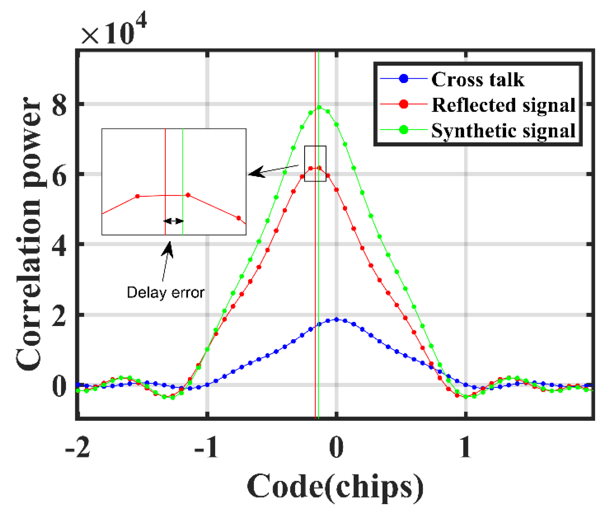
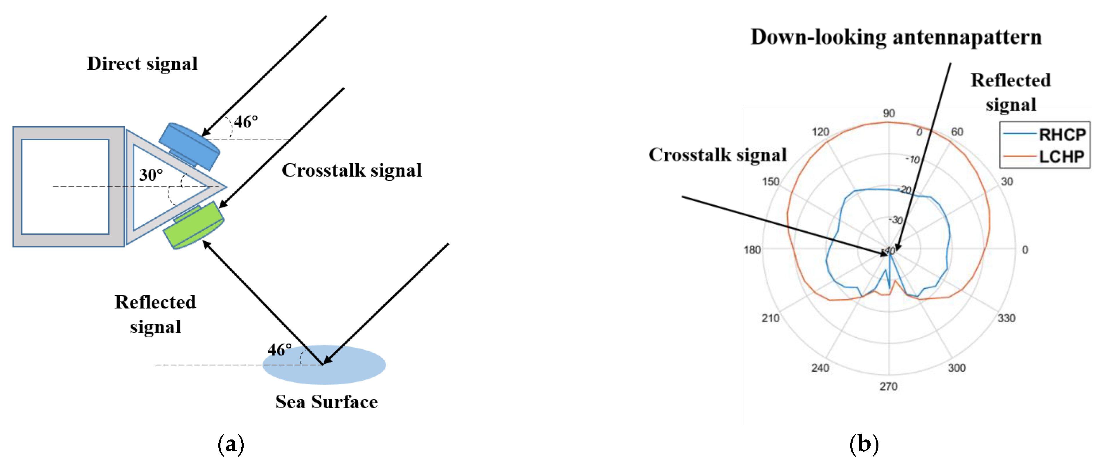
2.2. Signal Crosstalk
3. Results
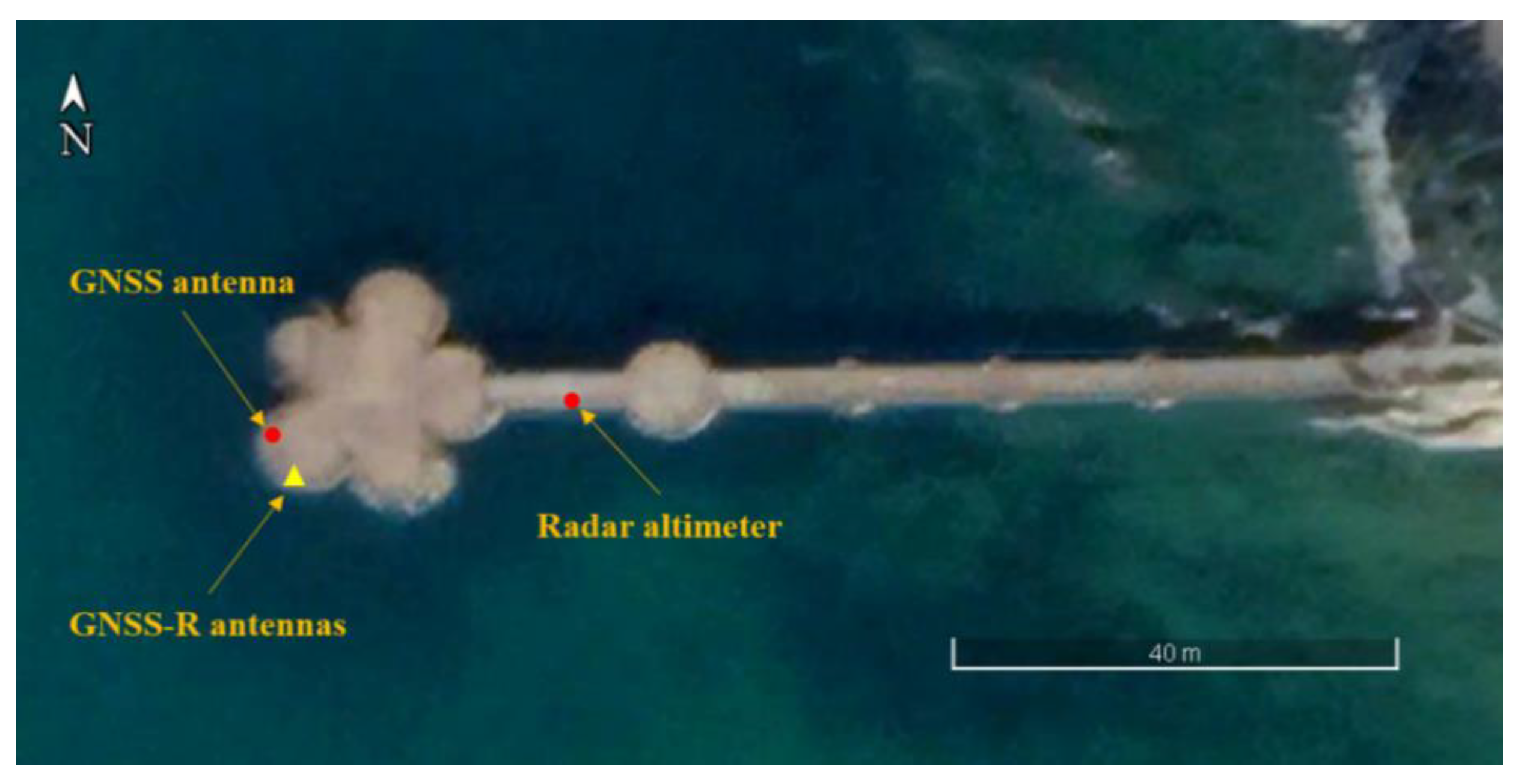
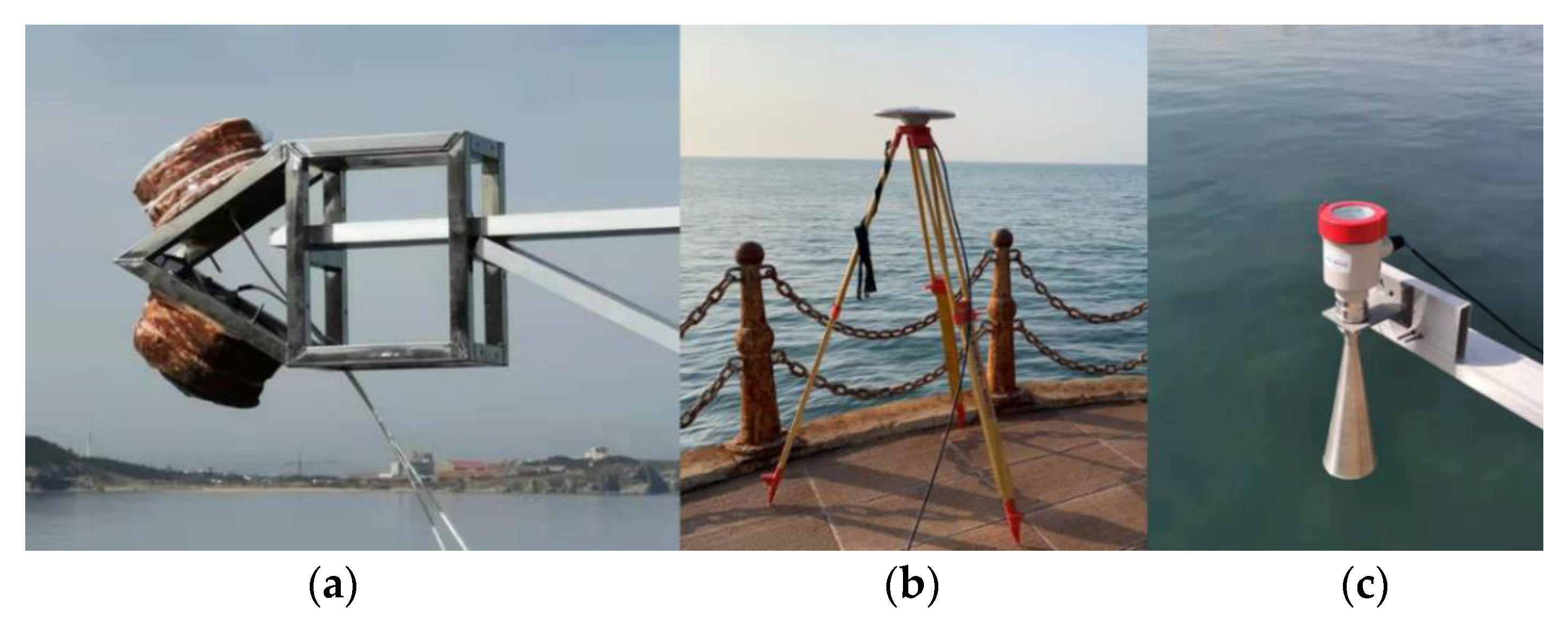
3.1. Experiment
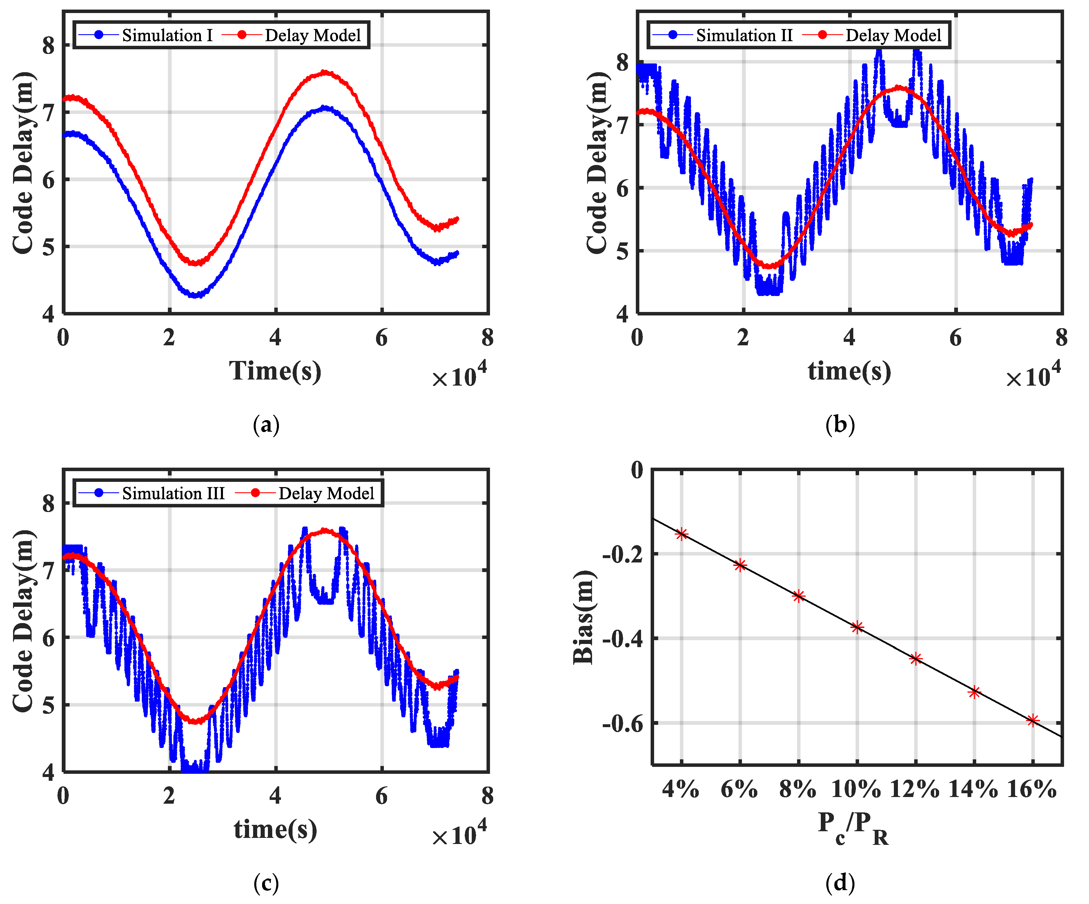
3.2. Crosstalk Effect Simulation

3.3. Crosstalk Effect in the Experiment
3.4. Crosstalk Effect Mitigation
4. Discussion
5. Conclusions
Author Contributions
Funding
Institutional Review Board Statement
Informed Consent Statement
Data Availability Statement
Acknowledgments
Conflicts of Interest
References
- Melet, A.; Meyssignac, B.; Almar, R.; Le Cozannet, G. Under-estimated wave contribution to coastal sea-level rise. Nat. Clim. Chang. 2018, 8, 234–239. [Google Scholar] [CrossRef]
- Liu, Y.; Kerkering, H.; Weisberg, R.H. Introduction to Coastal Ocean Observing Systems. In Coastal Ocean Observing Systems; Elsevier Inc.: Amsterdam, The Netherlands, 2015; pp. 1–10. ISBN 9780128020616. [Google Scholar]
- Cazenave, A.; Cozannet, G. Le Sea level rise and its coastal impacts. Earth’s Future 2014, 2, 15–34. [Google Scholar] [CrossRef]
- Martin-Neira, M. A passive reflectometry and interferometry system (PARIS): Application to ocean altimetry. ESA J. 1993, 17, 331–355. [Google Scholar]
- Löfgren, J.S.; Haas, R.; Scherneck, H.G. Sea level time series and ocean tide analysis from multipath signals at five GPS sites in different parts of the world. J. Geodyn. 2014, 80, 66–80. [Google Scholar] [CrossRef] [Green Version]
- Wang, N.; Xu, T.; Gao, F.; Xu, G. Sea level estimation based on GNSS dual-frequency carrier phase linear combinations and SNR. Remote Sens. 2018, 10, 470. [Google Scholar] [CrossRef] [Green Version]
- Wang, X.; He, X.; Zhang, Q. Evaluation and combination of quad-constellation multi-GNSS multipath reflectometry applied to sea level retrieval. Remote Sens. Environ. 2019, 231, 111229. [Google Scholar] [CrossRef]
- Santamaría-Gómez, A.; Watson, C.; Gravelle, M.; King, M.; Wöppelmann, G. Levelling co-located GNSS and tide gauge stations using GNSS reflectometry. J. Geod. 2015, 89, 241–258. [Google Scholar] [CrossRef]
- Larson, K.M.; Ray, R.D.; Williams, S.D.P. A 10-year comparison of water levels measured with a geodetic GPS receiver versus a conventional tide gauge. J. Atmos. Ocean. Technol. 2017, 34, 295–307. [Google Scholar] [CrossRef] [Green Version]
- Larson, K.M.; Löfgren, J.S.; Haas, R. Coastal sea level measurements using a single geodetic GPS receiver. Adv. Space Res. 2013, 51, 1301–1310. [Google Scholar] [CrossRef] [Green Version]
- Wu, J.; Chen, Y.; Gao, F.; Guo, P.; Wang, X.; Niu, X.; Wu, M.; Fu, N. Sea Surface Height Estimation by Ground-Based BDS GEO Satellite Reflectometry. IEEE J. Sel. Top. Appl. Earth Obs. Remote Sens. 2020, 13, 5550–5559. [Google Scholar] [CrossRef]
- Martín-Neira, M.; Caparrini, M.; Font-Rossello, J.; Lannelongue, S.; Serra Vallmitjana, C. The PARIS Concept: An Experimental Demonstration of Sea Surface Altimetry Using GPS Reflected Signals. IEEE Trans. Geosci. Remote Sens. 2001, 39, 142–150. [Google Scholar] [CrossRef] [Green Version]
- Lowe, S.T.; Zuffada, C.; Chao, Y.; Kroger, P.; Young, L.E.; Labrecque, J.L. 5-cm-precision aircraft ocean altimetry using GPS reflections. Geophys. Res. Lett. 2002, 29, 13-1–13-4. [Google Scholar] [CrossRef] [Green Version]
- Li, W.; Cardellach, E.; Fabra, F.; Ribo, S.; Rius, A. Assessment of Spaceborne GNSS-R Ocean Altimetry Performance Using CYGNSS Mission Raw Data. IEEE Trans. Geosci. Remote Sens. 2020, 58, 238–250. [Google Scholar] [CrossRef]
- Gao, F.; Xu, T.; Wang, N.; He, Y.; Luo, X. A shipborne experiment using a dual-antenna reflectometry system for GPS/BDS code delay measurements. J. Geod. 2020, 94, 88. [Google Scholar] [CrossRef]
- Rius, A.; Fabra, F.; Ribo, S.; Arco, J.C.; Oliveras, S.; Cardellach, E.; Camps, A.; Nogues-Correig, O.; Kainulainen, J.; Rohue, E.; et al. PARIS Interferometric Technique proof of concept: Sea surface altimetry measurements. In Proceedings of the 2012 IEEE International Geoscience and Remote Sensing Symposium, Munich, Germany, 22–27 July 2012; pp. 7067–7070. [Google Scholar] [CrossRef]
- Cardellach, E.; Li, W.; Rius, A.; Semmling, M.; Wickert, J.; Zus, F.; Ruf, C.S.; Buontempo, C. First Precise Spaceborne Sea Surface Altimetry with GNSS Reflected Signals. IEEE J. Sel. Top. Appl. Earth Obs. Remote Sens. 2020, 13, 102–112. [Google Scholar] [CrossRef]
- Pascual, D.; Park, H.; Onrubia, R.; Arroyo, A.A.; Querol, J.; Camps, A. Crosstalk Statistics and Impact in Interferometric GNSS-R. IEEE J. Sel. Top. Appl. Earth Obs. Remote Sens. 2016, 9, 4621–4630. [Google Scholar] [CrossRef] [Green Version]
- Alonso-Arroyo, A.; Querol, J.; Lopez-Martinez, C.; Zavorotny, V.U.; Park, H.; Pascual, D.; Onrubia, R.; Camps, A. SNR and standard deviation of cGNSS-R and iGNSS-R scatterometric measurements. Sensors 2017, 17, 183. [Google Scholar] [CrossRef] [PubMed] [Green Version]
- Lubeigt, C.; Ortega, L.; Vilà-Valls, J.; Lestarquit, L.; Chaumette, E. On the impact and mitigation of signal crosstalk in ground-based and low altitude airborne GNSS-R. Remote Sens. 2021, 13, 1085. [Google Scholar] [CrossRef]
- Onrubia, R.; Pascual, D.; Park, H.; Camps, A.; Rüdiger, C.; Walker, J.P.; Monerris, A. Satellite cross-talk impact analysis in airborne interferometric global navigation satellite system-reflectometry with the microwave interferometric reflectometer. Remote Sens. 2019, 11, 1120. [Google Scholar] [CrossRef] [Green Version]
- Gao, F.; Xu, T.; Meng, X.; Wang, N.; He, Y.; Ning, B. A Coastal Experiment for GNSS-R Code-Level Altimetry Using BDS-3 New Civil Signals. Remote Sens. 2021, 13, 1378. [Google Scholar] [CrossRef]
- Kucwaj, J.C.; Stienne, G.; Reboul, S.; Choquel, J.B.; Benjelloun, M. Accurate Pseudorange Estimation by Means of Code and Phase Delay Integration: Application to GNSS-R Altimetry. IEEE J. Sel. Top. Appl. Earth Obs. Remote Sens. 2016, 9, 4854–4864. [Google Scholar] [CrossRef]
- He, Y.; Gao, F.; Xu, T.; Meng, X.; Wang, N. Coastal Altimetry Using Interferometric Phase from GEO Satellite in Quasi-Zenith Satellite System. IEEE Geosci. Remote Sens. Lett. 2021, 1–5. [Google Scholar] [CrossRef]
- Yang, Y.; Mao, Y.; Sun, B. Basic performance and future developments of BeiDou global navigation satellite system. Satell. Navig. 2020, 1, 1. [Google Scholar] [CrossRef] [Green Version]
- Gao, F.; Xu, T.; Wang, N.; Jiang, C.; Du, Y.; Nie, W.; Xu, G. Spatiotemporal evaluation of GNSS-R based on future fully operational global multi-GNSS and eight-LEO constellations. Remote Sens. 2018, 10, 67. [Google Scholar] [CrossRef] [Green Version]
- Wang, K.; Chen, P.; Zaminpardaz, S.; Teunissen, P.J.G. Precise regional L5 positioning with IRNSS and QZSS: Stand-alone and combined. GPS Solut. 2019, 23, 10. [Google Scholar] [CrossRef] [Green Version]
- Nadarajah, N.; Khodabandeh, A.; Teunissen, P.J.G. Assessing the IRNSS L5-signal in combination with GPS, Galileo, and QZSS L5/E5a-signals for positioning and navigation. GPS Solut. 2016, 20, 289–297. [Google Scholar] [CrossRef]
- Cabinet Office. Quasi-Zenith Satellite System Performance Standard (PS-QZSS-001); Cabinet Office: Tokyo, Japan, 2018; Volume 33. [Google Scholar]
- Suzuki, T.; Kubo, N. GNSS-SDRLIB: An open-source and real-time GNSS software defined radio library. In Proceedings of the 27th International Technical Meeting of the Satellite Division of the Institute of Navigation (ION GNSS 2014), Tampa, FL, USA, 8–12 September 2014; Volume 2, pp. 1364–1375. [Google Scholar]
- Zavorotny, V.U.; Voronovich, A.G. Scattering of GPS signals from the ocean with wind remote sensing application. IEEE Trans. Geosci. Remote Sens. 2000, 38, 951–964. [Google Scholar] [CrossRef] [Green Version]
- Zavorotny, V.U.; Gleason, S.; Cardellach, E.; Camps, A. Tutorial on remote sensing using GNSS bistatic radar of opportunity. IEEE Geosci. Remote Sens. Mag. 2014, 2, 8–45. [Google Scholar] [CrossRef] [Green Version]
- Liu, W.; Beckheinrich, J.; Semmling, M.; Ramatschi, M.; Vey, S.; Wickert, J.; Hobiger, T.; Haas, R. Coastal Sea-Level Measurements Based on GNSS-R Phase Altimetry: A Case Study at the Onsala Space Observatory, Sweden. IEEE Trans. Geosci. Remote Sens. 2017, 55, 5625–5636. [Google Scholar] [CrossRef]
- Yu, K.; Li, Y.; Chang, X. Snow Depth Estimation Based on Combination of Pseudorange and Carrier Phase of GNSS Dual-Frequency Signals. IEEE Trans. Geosci. Remote Sens. 2019, 57, 1817–1828. [Google Scholar] [CrossRef]
- Yu, K.; Ban, W.; Zhang, X.; Yu, X. Snow depth estimation based on multipath phase combination of GPS triple-frequency signals. IEEE Trans. Geosci. Remote Sens. 2015, 53, 5100–5109. [Google Scholar] [CrossRef]
- Nievinski, F.G.; Larson, K.M. Forward modeling of GPS multipath for near-surface reflectometry and positioning applications. GPS Solut. 2014, 18, 309–322. [Google Scholar] [CrossRef]
- Huang, N.E.; Shen, Z.; Long, S.R.; Wu, M.C.; Snin, H.H.; Zheng, Q.; Yen, N.C.; Tung, C.C.; Liu, H.H. The empirical mode decomposition and the Hubert spectrum for nonlinear and non-stationary time series analysis. Proc. R. Soc. A Math. Phys. Eng. Sci. 1998, 454, 903–995. [Google Scholar] [CrossRef]
- Beckheinrich, J.; Hirrle, A.; Schön, S.; Beyerle, G.; Semmling, M.; Wickert, J. Water level monitoring of the Mekong Delta using GNSS reflectometry technique. In Proceedings of the 2014 IEEE Geoscience and Remote Sensing Symposium, Quebec City, QC, Canada, 13–18 July 2014; pp. 3798–3801. [Google Scholar]
- Zhang, S.; Liu, K.; Liu, Q.; Zhang, C.; Zhang, Q.; Nan, Y. Tide variation monitoring based improved GNSS-MR by empirical mode decomposition. Adv. Space Res. 2019, 63, 3333–3345. [Google Scholar] [CrossRef]
- Axelrad, P.; Larson, K.; Jones, B. Use of the correct satellite repeat period to characterize and reduce site-specific multipath errors. In Proceedings of the 18th International Technical Meeting of the Satellite Division of The Institute of Navigation (ION GNSS 2005), Long Beach, CA, USA, 13–16 September 2005; pp. 2638–2648. [Google Scholar]


| Methods | Std (cm) | Mean (cm) | RMSE (cm) |
|---|---|---|---|
| Code delay | 435.0 | −36.2 | 436 |
| Mean filter (1 min) | 30.1 | −35.2 | 46.3 |
| Mean filter(5 min) | 24.6 | −35.5 | 43.2 |
| EMD | 9.8 | −36.0 | 37.2 |
| Mean filter (1 min) (Bias removed) | 30.2 | −1.4 | 30.1 |
| Mean filter (5 min) (Bias removed) | 24.5 | −1.6 | 24.5 |
| EMD(Bias removed) | 9.3 | −1.8 | 9.5 |
Publisher’s Note: MDPI stays neutral with regard to jurisdictional claims in published maps and institutional affiliations. |
© 2021 by the authors. Licensee MDPI, Basel, Switzerland. This article is an open access article distributed under the terms and conditions of the Creative Commons Attribution (CC BY) license (https://creativecommons.org/licenses/by/4.0/).
Share and Cite
He, Y.; Xu, T.; Gao, F.; Wang, N.; Meng, X.; Ning, B. Analysis and Mitigation of Crosstalk Effect on Coastal GNSS-R Code-Level Altimetry Using L5 Signals from QZSS GEO. Remote Sens. 2021, 13, 4553. https://doi.org/10.3390/rs13224553
He Y, Xu T, Gao F, Wang N, Meng X, Ning B. Analysis and Mitigation of Crosstalk Effect on Coastal GNSS-R Code-Level Altimetry Using L5 Signals from QZSS GEO. Remote Sensing. 2021; 13(22):4553. https://doi.org/10.3390/rs13224553
Chicago/Turabian StyleHe, Yunqiao, Tianhe Xu, Fan Gao, Nazi Wang, Xinyue Meng, and Baojiao Ning. 2021. "Analysis and Mitigation of Crosstalk Effect on Coastal GNSS-R Code-Level Altimetry Using L5 Signals from QZSS GEO" Remote Sensing 13, no. 22: 4553. https://doi.org/10.3390/rs13224553
APA StyleHe, Y., Xu, T., Gao, F., Wang, N., Meng, X., & Ning, B. (2021). Analysis and Mitigation of Crosstalk Effect on Coastal GNSS-R Code-Level Altimetry Using L5 Signals from QZSS GEO. Remote Sensing, 13(22), 4553. https://doi.org/10.3390/rs13224553