Article

Toward a Standardized Encoding of Remote Sensing Geo-Positioning Sensor Models

1
Department of Earth System Science, Tsinghua University, Beijing 100084, China
2
Standardisation Department, Institut National de l’Information Géographique et Forestière (IGN), 94165 Saint Mandé, France
3
Center for Spatial Information Science and Systems, George Mason University, Fairfax, VA 20030, USA
*
Authors to whom correspondence should be addressed.
Remote Sens. 2020, 12(9), 1530; https://doi.org/10.3390/rs12091530
Submission received: 23 March 2020 / Revised: 6 May 2020 / Accepted: 6 May 2020 / Published: 11 May 2020
(This article belongs to the Section Remote Sensing Image Processing)

Abstract

:
Geolocation information is an important feature of remote sensing image data that is captured through a variety of passive or active observation sensors, such as push-broom electro-optical sensor, synthetic aperture radar (SAR), light detection and ranging (LIDAR) and sound navigation and ranging (SONAR). As a fundamental processing step to locate an image, geo-positioning is used to determine the ground coordinates of an object from image coordinates. A variety of sensor models have been created to describe geo-positioning process. In particular, Open Geospatial Consortium (OGC) has defined the Sensor Model Language (SensorML) specification in its Sensor Web Enablement (SWE) initiative to describe sensors including the geo-positioning process. It has been realized using syntax from the extensible markup language (XML). Besides, two standards defined by the International Organization for Standardization (ISO), ISO 19130-1 and ISO 19130-2, introduced a physical sensor model, a true replacement model, and a correspondence model for the geo-positioning process. However, a standardized encoding for geo-positioning sensor models is still missing for the remote sensing community. Thus, the interoperability of remote sensing data between application systems cannot be ensured. In this paper, a standardized encoding of remote sensing geo-positioning sensor models is introduced. It is semantically based on ISO 19130-1 and ISO 19130-2, and syntactically based on OGC SensorML. It defines a cross mapping of the sensor models defined in ISO 19130-1 and ISO 19130-2 to the SensorML, and then proposes a detailed encoding method to finalize the XML schema (an XML schema here is the structure to define an XML document), which will become a profile of OGC SensorML. It seamlessly unifies the sensor models defined in ISO 19130-1, ISO 19130-2, and OGC SensorML. By enabling a standardized description of sensor models used to produce remote sensing data, this standard is very promising in promoting data interoperability, mobility, and integration in the remote sensing domain.

Graphical Abstract

1. Introduction

Remote sensing has been widely used to monitor Earth’s surface environment and its changes over time that are associated with reflectance and other surface properties of Earth. One of the key characteristics of remote sensing data is that it conveys ground location information, which is retrieved through geo-positioning processes [1].
According to the World Meteorological Organization (WMO) [2], approximately 950 types of remote sensors (including both Earth observation instruments and solar/space environment monitors) have been deployed on more than 700 satellites up to 2019. Because of the diversity of sensor types, data from different producers may contain different parametric information, lack parameters required to describe the sensor, or lack ancillary information necessary for geo-positioning and analyzing the data. A more standard way to describe sensors and platforms can enable intelligent discovery of the right sensor at the right time and location with the right quality, which also improves sensor interoperation [3]. Figure 1 presents an overview of the UML packages defined in two important sensor model related standards: OGC SensorML and ISO 19130-1/19130-2.

1.1. Sensor Models for Geo-Positioning Process and Related International Standards

A geo-positioning process is a type of location model to geo-register or co-register observations from a sensor (particularly remote sensors) [4]. It determines the relationship between the image coordinates and its geo-position along with other auxiliary information (the performance and quality of measurement characteristics, an explicit description of the process, and physical characteristics). The geo-positioning process is part of a sensor model [1]. Among these processes, the geo-positioning process serves as one of the most fundamental and indispensable links to locate an image. It can help provide a coherent framework for data processing.
To confront the above-mentioned issues, two major international standards organizations are currently making efforts to devise standards for geo-positioning sensor models, namely ISO/TC 211 (the International Organization for Standardization/Technical Committee 211) which is about standardization in the field of digital geographic information [5] and OGC (the Open Geospatial Consortium) which provides geospatial location information and services [6]. Both OGC and ISO standards are international standards. However, OGC standards are developed by concerned parties interested in the standard while ISO standards are developed by experts contributed by and approved by the member nations. OGC is an official external liaison organization of ISO TC 211 [7].
As a work item of the ISO/TC 211 and the ISO 19100 series, ISO 19130 is a standard series that specifies the geolocation information that an imagery data provider shall supply for users to estimate the Earth location of image data using a physical sensor model (PSM, the mathematical representation of the physics and geometry of the image sensing system [1]), a true replacement model (TRM, produced using a PSM whose formulae directly describing the relationship between image coordinates and Earth coordinates [1]), or a correspondence model (CM, using image information and ground control points only for georeferencing [1]). The ISO 19130 series has published two standards: ISO 19130-1 and ISO 19130-2. The first part (ISO 19130-1) defines sensor models for passive electro-optical visible/infrared (IR) sensors (namely frame, pushbroom, and whiskbroom sensors) and for an active sensing system [Synthetic Aperture Radar (SAR)], and metadata for ground control points (GCPs). The second part of the standard (ISO 19130-2) [8] further defines sensor models for SAR, InSAR, light detection and ranging (lidar), and sound navigation and ranging (sonar), along with the metadata needed for the aerial triangulation of airborne and spaceborne images. ISO 19130-1 and ISO 19130-2 rigorously define the physical and geometric information of a sensor and the functions (a function here is a clearly defined expression that can receive inputs and produce outputs) and parameters for describing a PSM, TRM, and CM, along with GCPs. They work together to determine the geographic position of images from sensors.
The other standard organization, OGC, not only fosters and supports a global conversation to create free and publicly available geospatial standards, but collaborates with other standard development organizations including ISO/TC 211 [9]. OGC defines interfaces and encodings for sensor devices and data through Sensor Web Enablement (SWE) [10] to enable sharing sensor data over the Web. Tremendous amounts of sensor data around the world are generated from the World-Wide Sensor Web [11,12]. For example, Durbha [13] developed a standards-based approach to remotely configure sensors deployed in marine observation platforms through the SWE framework.
Sensor Model Language 2.0 (SensorML; here, SensorML represents SensorML 2.0.) [4] is a very important standard in SWE. It provides a well-defined and robust way of describing the process of measurement and observation, along with the associated processing components. SensorML uses the process concept to describe components including sensors, sensor systems, observations and measurement. A process receives an input through algorithm and sets parameter values, and generates outputs [4]. Geo-positioning plays an important role in SensorML as a process. The aims of SensorML include one clause that it supports the geolocation of observed values.
SensorML has been widely adopted and implemented in the remote sensing society [14,15,16]. Some researchers used SensorML to strengthen the connection between sensors. For example, Chen constructs a geoprocessing e-Science workflow model for sensor observations in the form of observation processes based on SensorML [17]. Some researchers built their sensor systems or sensor webs based on SensorML. For example, Poland launched an air quality monitoring network in Nowy Sacz using SensorML and Observations & Measurements (O&M) to describe the sensor [18]. Sorribas [19] used a SensorML profile and O&M profile to express research vessels and fixed stations to enable the discovery and exchange of marine observations and improve the descriptions of complex instrumentation and data structures. AFIS (The Advanced Fire Information System) in South Africa [12] used SensorML to describe their satellite sensor models in a sensor web application for regional vegetation fire detection. SensorML is also used to improve interoperability of unattended ground sensors from different manufacturers [20]. Besides, lots of SensorML profiles are developed and bring more semantics to SensorML. The Starfish Fungus Language (StarFL) is a profile to further constrain the use and expressiveness of SensorML to improve interoperability [21].

1.2. Implementable Sensor Model for Geo-Positioning

Although both SensorML and ISO 19130 series standards describe sensor models for geo-positioning, many differences between them have been observed (see Table 1). ISO 19130-1 and ISO 19130-2 present detailed characteristics of passive observation and active observation sensor models directly, and they only provide unified modeling language (UML) descriptions along with the data dictionaries. It is highly expected to have an implementable schema to ensure interoperable encoding results. The SensorML specification defines a comprehensive and concrete conceptual model along with encoding methods using the extensible mark language (XML) Schema, but it is a relatively soft-typing (which takes advantages of both static and dynamic typing where typing means defining the data type). The SensorML data model aims at covering almost all types of sensors. Therefore, it is designed to be general-purpose, which makes it difficult to be directly applied to rigorous sensor geo-positioning models. Moreover, SensorML does not have a specific metadata description and definition of the geo-positioning process. Reconceptualization, redefinition, or some extension of SensorML are needed to support the encodings of geo-positioning sensor models.
To bridge this gap, a SensorML profile for the imagery sensor geo-positioning process is put forward in this paper as a semantic mediation between ISO 19130-1, ISO 19130-2, and OGC SensorML standards to enable a standardized encoding of geo-positioning sensor models. This effort helps to ensure a truly interoperable description of a variety of remote sensing geo-positioning sensor models for the remote sensing community. It will benefit various parties, including academia, business, industries, governments, and consumers.

1.3. Goals

This paper describes a solution to bridge the two aforementioned standards. From OGC side, the result will become a profile of SensorML and from ISO/TC 211 side, it will form into a technical specification of ISO (named as ISO 19130-3). Specifically, it has the following goals:
  • Defining a SensorML profile within the geo-positioning scope;
  • Implementing ISO 19130-1 and ISO 19130-2 based on SensorML syntactic;
  • Further restricting SensorML elements based on ISO sensor model semantics;
  • Giving examples on how to implement the encoding;
  • Improving sensors’ interoperability in terms of the geo-positioning process.
This profile requires underlying alignment between OGC and ISO terminology and semantics for image geo-positioning. Normally, ISO/TC 211 has the ability to automatically interpret UML models into XML schemas. This paper, instead of introducing an XML schema just based on the ISO 19130 UML models, leverages OGC SensorML by first introducing a semantic mapping from the ISO sensor model elements to OGC SensorML, and then defining a SensorML profile to fully support encoding of the imagery sensor models for geo-positioning process for remote sensors.

2. Materials and Methods

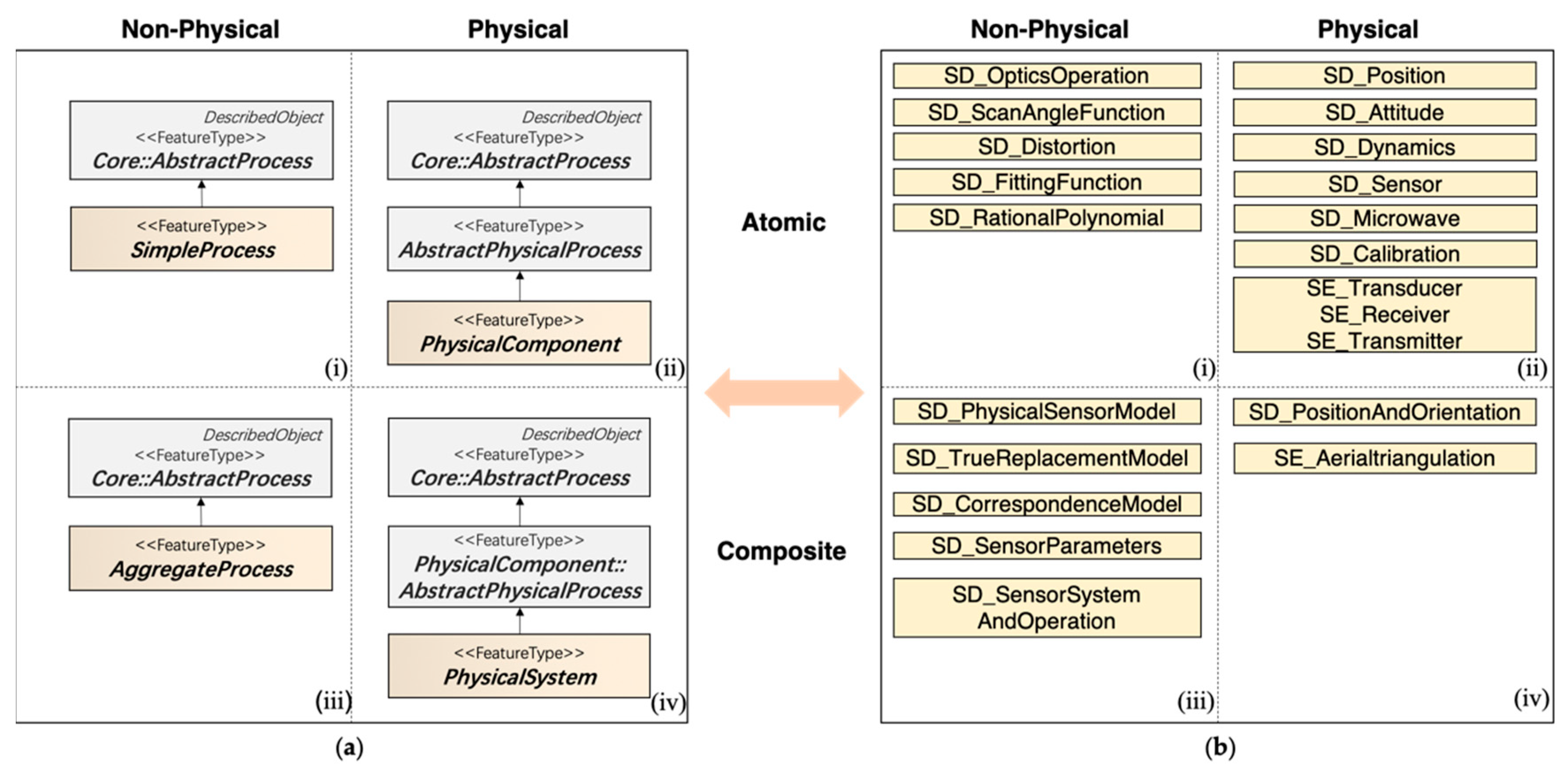
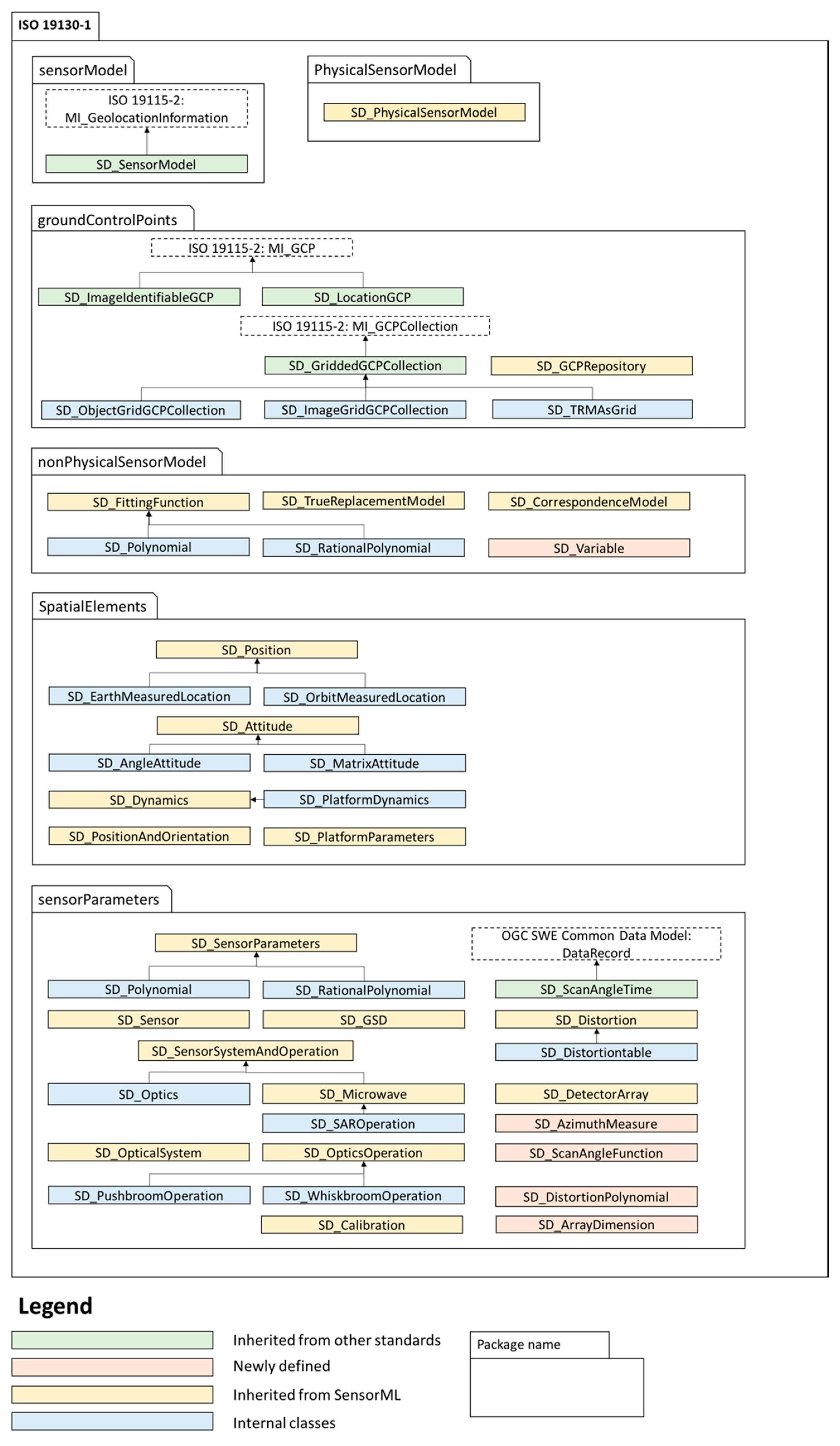
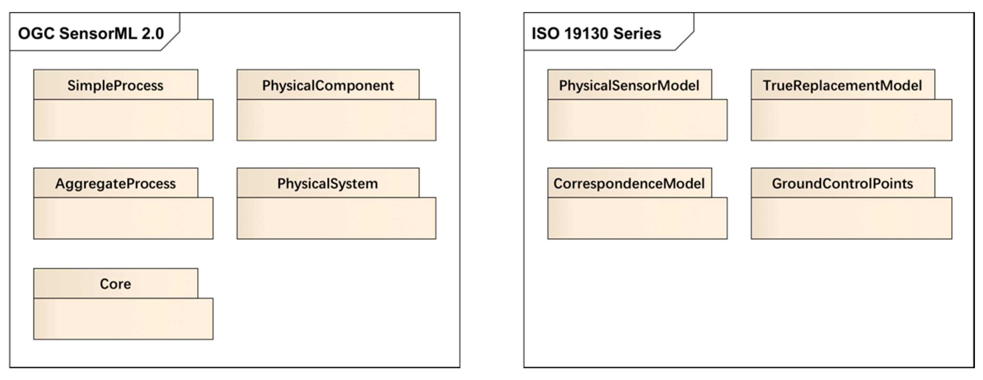
2.1. Analysis of Sensor Models and the Two Standards

As mentioned in the Introduction, SensorML and ISO 19130-1 and ISO 19130-2 are built for different purposes, thus resulting in different specifications (Figure 1).
In ISO 19130-1 and ISO 19130-2, sensor models are classified as geolocating models including PSM, TRM, and georeferencing models including CM according to their various mathematical principles in different applicable scenarios (Table 2). Some common elements (GCPs, calibration data, and code lists) are declared to support these models. The selection of sensor models is determined by sensor types (namely, frame sensor, pushbroom sensor, whiskbroom sensor, SAR, InSAR, lidar, sonar) and by mounting platforms such as airborne or spaceborne. A PSM needs description of classes for describing metadata, model approaches, quality information, sensor parameters, location, and orientation. A TRM needs description of fitting functions, model approaches, and quality information. A CM needs a description of GCPs for geo-positioning along with fitting functions.
All components in SensorML are modeled as processes: physical processes (e.g., sensors, detectors, and systems) and non-physical processes (e.g., observations, measurement, and mathematical operations or functions). A process takes inputs and produces outputs through well-defined methods and parameters. All these basic elements can therefore be interconnected to form aggregate processes (like sensor workflows, chains, and networks).
The root class of SensorML is DescribedObject, which functions as the basis for most classes. DescribedObject defines a specific set of metadata (including language, security constraints, legal constraints, identification information etc.,) for all process classes in SensorML. AbstractProcess is a derived class from DescribedObject along with additional properties of typeOf, configuration, featuresOfInterest, inputs, outputs, parameters, and modes. The four derived classes (SimpleProcess, PhysicalComponent, PhysicalSystem, AggregateProcess) list relatively comprehensive and extendible properties to describe a sensor and related processes. However, the flexibility of SensorML cannot ensure a clear and rigorous definition for a geo-positioning process. Further, it cannot specify the minimum requirements and other constraints for elements of a sensor model.
Although SensorML does not rigorously specify any semantic model for geo-positioning, it enables users to define sensor models using SensorML’s processes model. Botts [22] gives an example of how to describe a frame sensor model using SensorML 1.0. The encoding implementation of this example frame sensor model is shown in Figure 2. The full XML code of this example can be found in Annex B of OGC 08-071 document [22].
Figure 2 shows that the information needed for a frame sensor model includes the value of inputs, outputs, and parameters. The name of each property might vary from case to case. For example, the distortion information in this case is defined by parameters of affine distortion coefficients, radial distortion coefficients, and decentering coefficients. In other cases, distortion information may be a distortion table or a distortion polynomial. This kind of difference reduces interoperability between different sensor systems. Furthermore, SensorML does not give instructions on how to align with geo-positioning models, which may cause confusion for users.
As indicated in ISO 19130-1 and ISO 19130-2, every element has an applicable semantic meaning. Compared with SensorML, the geolocation information for a sensor model is constrained to specific data types or formats, relatively narrow value ranges, strict dependencies, or the number of occurrence. In ISO 19130-1, for instance, the SD_Dynamics (all classes defined in ISO 19130-1 have a prefix “SD”) and its derived classes provide the motion information of a body. All dynamic-related attributes are put under these classes. Because of SensorML’s high flexibility, SD_Dynamics may be encoded as a ParameterList (an element from SensorML, composed of a group of anyData value) or a SimpleProcess (an indivisible process). Users might face with multiple choices to encode SD_Dynamics. The related properties like attitude, velocity, acceleration, yaw, and heading will be in various forms as well. Therefore, the description of SD_Dynamics will differ from user to user, which is contrary to the aim of improving interoperability. Thus, an extension of SensorML classes to rigorously define data semantics and constraint for ISO sensor model elements is necessary. It avoids ambiguous definitions and provides users with clearer instructions when they encode geo-positioning models for sensors.

2.2. Design Principles

In order to map these sensor geo-positioning models in ISO 19130-1 and ISO 19130-2 to SensorML elements, the following principles are designed.
Principle 1.
For ISO sensor model elements that can perfectly match the context and content of SensorML classes, they can be directly implemented using the existing correspondence SensorML classes (Figure 3).
Principle 2.
ISO sensor model elements that share a similar context but differ in properties with SensorML classes will inherit the shared properties from SensorML classes and form into subclasses along with their unique properties. The inherited properties must meet other constraints, such as occurrence times or data type (Figure 4).
Principle 3.
For ISO sensor model elements that neither share a similar meaning nor the properties with SensorML classes, they cannot find a mapping to SensorML. Therefore, new classes are introduced to SensorML to meet these new requirements (Figure 5). For example, the SD_AzimuthMeasure is a class to describe the measurement of azimuth properties. SensorML does not have a similar element to azimuth information. Therefore, a new class is defined in ISO 19130-3 to fill this gap.
Referring to the aforementioned three principles, all classes of ISO 19130 series can be mapped, extended from SensorML or newly defined.

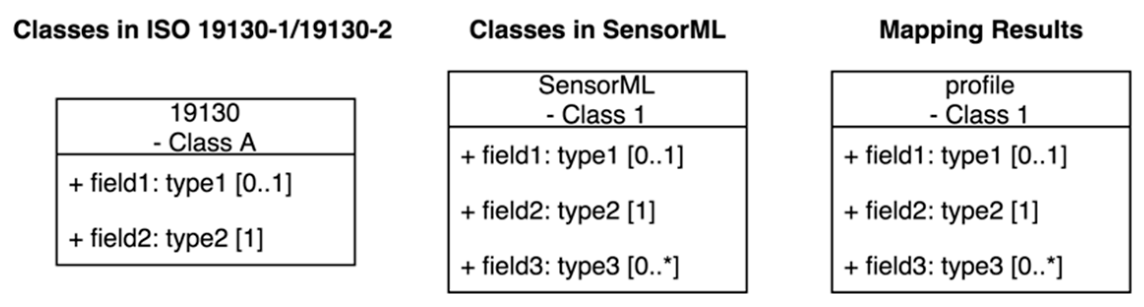
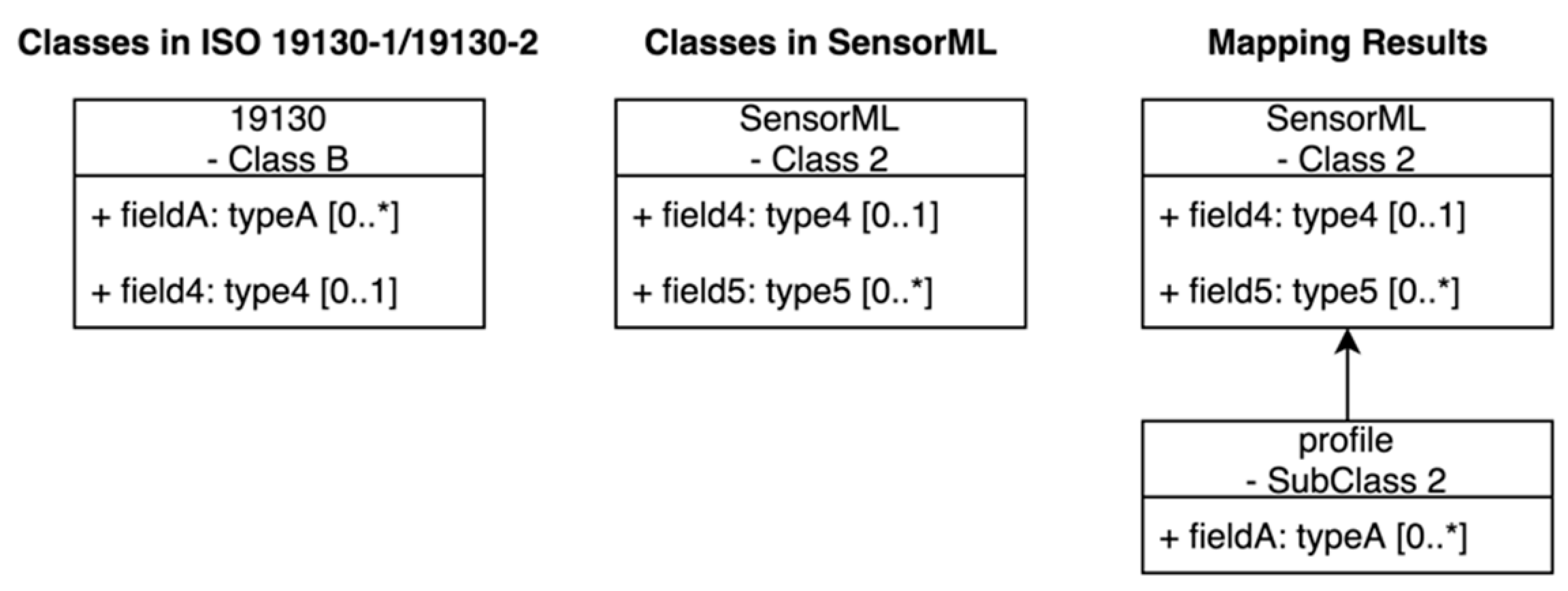
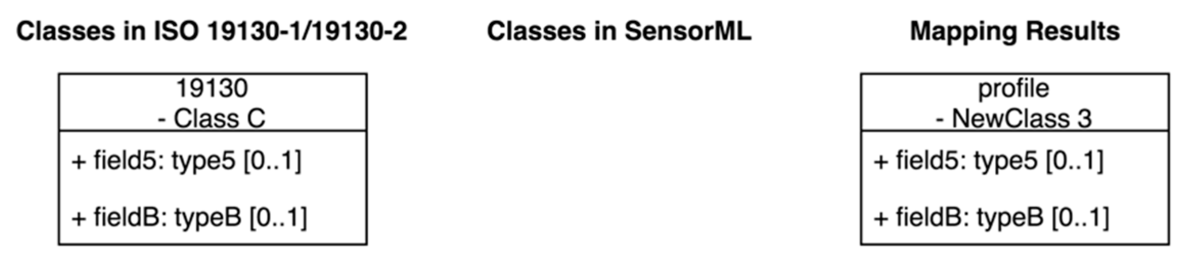
2.3. Semantic-Level Mapping

The three principles instruct how to rewrite a class from syntactic side. They do not tell us how to map classes from semantic side. An understanding of SensorML classes is important for the mapping. Table 3 lists all main classes of SensorML and their definitions. Main classes mean they are root or near root classes to derive other classes. Except for the Core class, which is a group of abstract classes serving as the root of the other five classes, the other five main classes are not abstract and can be used directly to describe these ISO sensor models.
The SimpleProcess, PhysicalComponent, PhysicalSystem, and AggregateProcess describe a process from dimensions that whether it is physical or non-physical, and atomic or composite (atomic or composite means indivisible or not). The PhysicalComponent and PhysicalSystem are both physical processes with real devices, while SimpleProcess and AggregateProcess (as well as configurableProcess) consist of one or more well-defined functions. In terms of atomic or composite side, the SimpleProcess and PhysicalComponent are indivisible processes, while AggregateProcess and PhysicalSystem are composites of several indivisible or composite processes. By classifying these classes, we are able to map corresponding ISO 19130-1 and ISO 19130-2 concepts and classes to SensorML.
Taking mapping SD_Sensor (from ISO 19130-1) to SensorML as an example, it can be mapped to the PhysicalComponent in SensorML.
Semantically, SD_Sensor describes a physical sensor’s information. The PhysicalComponent in SensorML is similar with SD_Sensor. The PhysicalComponent class represents real devices with spatio-temporal information. Besides, they not only share semantical similarity, but also some property similarities.
It defines calibration, mode, and operationalBand properties. The concept of PhysicalComponent is consistent with SD_Sensor, but properties of PhysicalComponent cannot perfectly match those of SD_Sensor (Principle 3). Therefore, a new class, sml19130:SD_Sensor is defined under the namespace sml19130 as a subclass of sml: PhysicalComponent. Among three properties of SD_Sensor, mode has a similar meaning as the modes property inherited from sml: PhysicalComponent. The operationalBand specifies the wavelengths information, inheriting the parameters property. The calibration matches the method property in SensorML, but its datatype (SD_Calibration) is a semantically tied process that needs further definition. Therefore, extended from PhysicalComponent, sml19130:SD_Sensor has the following schema design (found Figure 6).

2.4. Mapping Examples of ISO 19130 Three Main Sensor Models

The ISO 19130 three sensor models (PSM, TRM, CM) are derived from the root class SD_SensorModel. It provides sensor descriptions and geo-positioning model information as a subclass of MI_GeolocationInformation defined in ISO 19115-1 [23].
Three sensor models consist of different inputs and functions, which determine their related SensorML processes (Table 2).
The PSM, as the most precise model based on accurate physical data and GCP information, consists of two component classes: SD_SensorParameters and MI_GCPCollection (if ground point details are provided) or SD_GCPRepository (if ground point collection repository URL is provided). This comprises an aggregated class and essentially a non-physical process because of its mathematical representation.
The TRM is an alternative model based on PSMs when PSM requirements cannot be met or users do not want to bother with a PSM model. It has the same properties as PSMs of ground-to-image and image-to-ground functions, complete and rigorous error propagation, and adjustability. To construct a TRM, a series of processes like coordinate normalization, direct linear transform, grid interpolation, rigorous error propagation, and adjustability are involved [1]. Any of these components can be simple processes or aggregate processes. Therefore, a TRM is an aggregate process due to its aforementioned component processes.
The CM is a less precise model compared with PSMs and TRMs since it does not consider sensor systematic errors. Basically, the CM takes GCPs as inputs and completes the geo-positioning process by two groups of fitting functions. One is for three-dimensional-to-two-dimensional (3D-to-2D) models and the other is for 2D-to-2D models (similar to “registration”). Fitting functions of CMs are one or more polynomials (simple processes). Thus, CM is also an aggregate process.

3. Results

3.1. Mapping Results

In the preceding section, a general design principle for mapping between ISO 19130 and SensorML components and some examples are given. These principles guide the schema design of ISO 19130-3. The main classes of SensorML (Table 3) fall into four categories, namely physical, non-physical, atomic, and composite (See Figure 7a). A physical class usually has physical location representation, while a non-physical one does not. Based on the design principles proposed in Section 2.2., some classes of ISO 19130-1 and ISO 19130-2 fit into this four-category diagram. Figure 7 gives an overview of how these classes correlate with SensorML.
Apart from the classes shown in Figure 7, some ISO 19130 classes cannot match the SensorML concepts. Their definitions and properties are beyond SensorML’s scope, but are aligned with other international standards. For example, SD_GriddedGCPCollection, a class from ISO 19130-1 to describe a collection of gridded ground control points [1], is derived from ISO 19115-2 [24].

3.2. Overview of the Result

The mapping results form into a new schema. Figure 8 and Figure 9 illustrate the resulting proposed specification of ISO 19130-3. They also show how schemas are organized and defined. It is a profile of SensorML named as ISO 19130-3 under ISO 19130-1 and ISO 19130-2 semantics. Classes with similar functions and same prefix are put together in one package (a package is a group of semantically related elements [25]). The general SD_SensorModel class describing the basic sensor model is in the sensorModel package. The physicalSensorModel (PSM) and nonPhysicalSensorModel (including TRM and CM) are put in two separated packages. The groundControlPoints is a package containing GCP-related classes. The two most informative packages are spatialElements and sensorParameters. The sensorParameters is a group of parameters to define or set for a component or system. It consists of sensor parameters, distortion, detector array, sensor, sensor operations, microwave, calibration, transducer, receiver, and transmitter. The elements in spatialElements package describe spatial information, including position, attitude, dynamics, orientation, and aerial triangulation information. In Figure 8 and Figure 9, all classes in yellow are inherited from SensorML classes and classes in blue are their child classes. Classes in light orange are newly defined because of their unique properties or definitions. Finally, classes in light green are imported and extended from other standards, such as ISO 19115 Geographic Information — Metadata — Part 2: Extensions for Acquisition and Processing [24] and OGC SWE Common Data Model Encoding Standard [26].

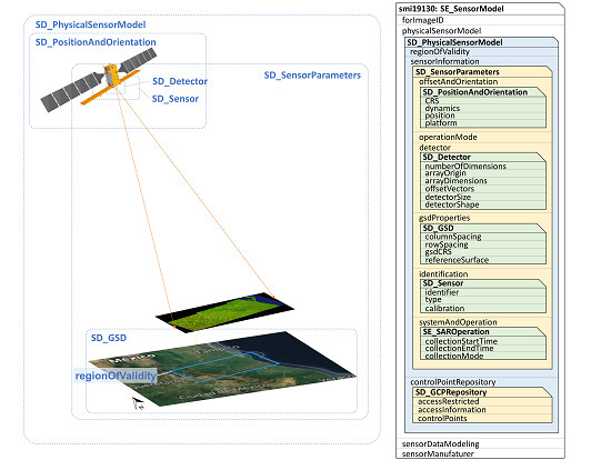
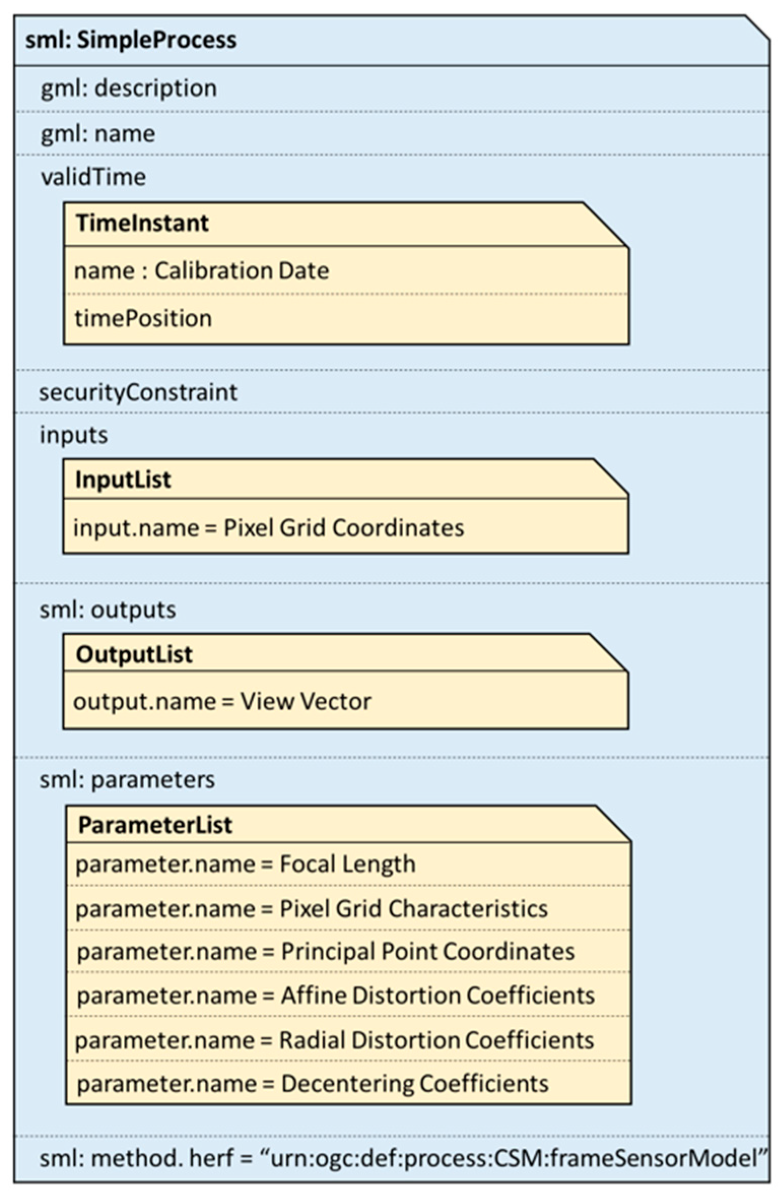
3.3. A Sensor Model Encoding Example

To directly show how to implement the schemas on an actual remote-sensing image for a geo-positioning process, a level-1 image (downloaded from Copernicus Sentinel data 2019, processed by ESA.) from Sentinel-1 satellite is given as an example [27]. The example image was acquired on 30 July, 2019 of path 5, frame 64 (Figure 10, path and frame denote the image position in Sentinel-1’s reference system).
Sentinel-1 comprises a constellation of two polar-orbiting satellites. Each satellite carries a single C-band SAR radar instrument that supports operation in dual polarization (HH+HV, VV+VH). The acquisition modes of Sentinel-1 include stripmap (SM), interferometric wide swath (IW), extra-wide swath (EW), and wave mode (WV). Because of the three acquisition modes and two polarization methods, every level-1 image product consists of six component images. The example image is one of level-1 six images. It is from Sentinel-1B satellite on IW mode and VH polarization method. Besides, the level-1 image has been geographically calibrated [28], which is suitable to illustrate the geo-positioning metadata.
Because this image was taken by a SAR sensor, the SE_SensorModel defined for active sensors in ISO 19130-2 is more suitable to describe the SAR geo-positioning information. The full code of the image’s sensor model metadata is given in the GitHub repository: https://github.com/THU-EarthInformationScienceLab/ISO-19130-3.
All of three sensor models, PSM, TRM, and CM, can describe its geo-positioning process. This paper only provides the PSM implementation example. More examples will be updated.
In general, it is necessary for a PSM to have sensor parameters and ground control points information. Sensor parameters include parameters of identification, offset and orientation, operational mode, detector information, ground sample distance properties, system and operation. Figure 11 gives the structure of these classes. The left-side image illustrates the main components to describe a sensor model and the right-side image shows the corresponding class structure and properties.
Table 4, Table 5, Table 6, Table 7, Table 8 and Table 9, using the proposed new schema from Section 3.2, we list the data type and value of every element, which are illustrated here to show how to implement the PSM of this image based on the result in Section 3.2.
According to the above paragraphs, SE_SensorModel is the root element of this instance, which is described in detail in Table 4. Table 5, Table 6, Table 7, Table 8 and Table 9, instances of physicalSensorModel, sensor Information, offsetAndOrientation, systemAndOrientation, and detector are given respectively. Their relationships are given in Figure 11. Every table corresponds to an xml instance file which can be found in the GitHub repository. The first column of each table lists all elements to describe this instance. The second column is the data type of the element and the last column provides an example value. Some of the values are from the real case while some are set manually to make it easier to understand (denoted within the bracket).
We name the instance of SE_SensorModel as S1_SensorModel (Table 4). Since SE_SensorModel is derived from MI_GeolocationInformation, it also inherits the properties. In this case, it is the ID property. However, the other three properties, physicalSensorModel, sensorDataModeling, and sensorManufacturer, are the newly defined properties of SE_SensorModel. The sensorDataModeling is a codelist of sensor data modeling methods, such as absolute value, basic sequential modeling, and collection plane. The sensor manufacturer is the manufacturer of this sensor.
The physicalSensorModel is a basic element of SE_SensorModel, which is composed of a set of properties (See Table 5).
In Table 5, regionOfValidity, sensorInformation, and controlPointRepository are defined for a physical sensor model, where regionOfValidity and sensorInformation are compulsory. The regionOfValidity property defines the geographical boundary of this image. The example image is rectangular, so three corner coordinates are enough to map image coverage. The sensorInformation contains most of the important parameters to describe the geo-positioning process of this image. The data type of sensorInformation is SD_SensorInformation which is further introduced in Table 6. Another element, controlPointRepository, is an URL linking to a group of ground control points to check and refine physicalSensorModel by correcting the geographic location of the image. The value of URL is given in accessInformation property.
The type of sensorInformation is SD_SensorParameters, which is an extension class from sml: physicalComponent (Table 6). It includes the sensor’s offset and orientation information (offsetAndOrientation), ground sampling distance properties (gsdProperties), identification (identification), detector (detector), operational mode (operationalMode), and the sensor’s operation information (systemAndOperation). The offsetAndOrientation provides detailed information of offset and orientation relative to the object on which the sensor is mounted. The operationalModes is implemented as sml: modes inherited from the base class (sml: physicalComponent).
The identification includes information about calibration, mode, and operationalBand properties of a sensor or, furthermore, information of an instrument. The systemAndOperation contains specific operational information of the sensor. In addition to collection start and end time, it must indicate whether the sensor is passive or active. The example image was taken by Sentinel-1 is a SAR sensor. Therefore, a SE_SAROperation class was chosen.
The operationalMode property is similar to the modes concept in SensorML. In this case, the operationalMode property shares the modes property from SensorML and is implemented by a string type. Here, the value is assigned to “Interferometric wide swath.”
Table 7, Table 8, and Table 9 describe the detail of offsetAndOrientation, systemAndOperation, and detector properties respectively.
The SD_PositionAndOrientation class is used to describe the offsetAndOrientation property. The offset is a vector indicating displacement between the origin of two coordinate systems and is a kind of value to restrict image geolocation, which is similar to the concept of the configuration property inherited from SensorML. Thus, it inherits the configuration property from SensorML directly.

4. Discussion

In this paper, a standardized encoding of remote sensing geo-positioning sensor models is put forward. It facilitates the integration of sensor model-related standards independently defined by OGC and ISO.
However, there are still lots of potential challenges for this standard. First, although the crosswalk between ISO sensor model and SensorML follows three principles in Section 2, some mapping results are not the best solution. Classes derived from SensorML do not have restrictions on the appearance of optional properties defined in SensorML. Therefore, inheriting those optional properties in the instance of this schema is technically valid but not logically correct. When following this standard to encode the sensor models, users are suggested to strictly follow the schema proposed in this standard to avoid ambiguity. Second, more efforts are needed to promote the applications of this standard and the resultant schema. In the remote sensing community, geo-positioning information is provided in various forms. Often it is included in the calibration files. In some cases, providers do not distribute a specific file to support the geo-positioning process, in which case users need to find information by themselves. Active adoption and application of this standard is critical to ensure a standardized description of the sensor models, and to promote the interoperability of a variety of remote sensing processing systems. Third, we believe it is now possible to include geo-positioning-related information in the imagery metadata by giving an encoding method of ISO 19130 sensor models. For example, ISO 19115-2, another standard related to geo-positioning process with a published encoding schema, has been implemented in some imagery metadata. Imagery with geo-positioning metadata on the web could be easily harnessed. Finally, both OGC and ISO/TC 211 review and if necessary revise their respect standards and technical specifications periodically. For example, when a new type of sensor is developed or commonly used, it may require the development or alteration of existing standards including this one. Comprehensive revision of this standard may be necessary when there are changes in related standards.

5. Conclusions

This paper presented a standardized encoding of remote sensing geo-positioning sensor models. It is semantically based on ISO 19130-1 and ISO 19130-2, and syntactically based on OGC SensorML. On the one hand, ISO 19130-1 and ISO 19130-2 define UML models of a variety of sensor models that are widely used for remote sensing data, but this series of standard lacks a concrete encoding specification. The UML models cannot guarantee a consistent encoding of sensor models defined in ISO 19130-1 and ISO 19130-2. On the other hand, OGC SensorML defines the sensor model including geo-location information but in a soft-typing way. It does not indicate the type of sensor, the specific geo-positioning process nor the auxiliary components.
This study proposed three principles toward a cross-mapping of the sensor models defined in ISO 19130-1 and ISO 19130-2 to SensorML, and then provided a detailed encoding standard to finalize the schema. Based on the process-oriented encoding mechanism of SensorML, PSMs, TRMs, and CMSs from ISO 19130-1 and ISO 19130-2 are clearly defined using the process concept consisting of their corresponding inputs, functions, parameters, and outputs, as well as other necessary elements (e.g., GCP information for the check or the refinement sensor models). Other related elements are defined as different process-based classes according to their non-physical or physical, atomic, or composite characteristics.
This encoding of remote sensing geo-positioning sensor models is actually a profile of OGC SensorML. It seamlessly unifies the sensor models defined in ISO 19130-1, ISO 19130-2, and OGC SensorML. It has been reviewed by international experts from member countries of ISO TC/211. It is expected to be fully endorsed and approved as the ISO 19130-3 standard.
By enabling a standardized description of sensor models used to produce remote sensing data, the resulting standard will promote data mobility, interoperability, and integration in the remote sensing domain, especially from the following three aspects. First of all, the geo-positioning process is important for data production in ground segment. However, most of them are independently designed and lack reusable models for geo-positioning. This proposed sensor model encoding standard is expected to fill this gap. Second, in emergency response situations, it is critical important to promptly and precisely align diverse image data acquired by different sensor systems. This standardized geo-positioning description helps facilitate data integration in this pre-processing step. Last but not the least, in the sensor web context, it is necessary to accurately set or obtain the geometric features of various sensors and platforms. The encoding method proposed in this paper helps avoid developing different adaptations and private protocols for each sensor.

Author Contributions

This paper is conceptualized by Y.B. and L.D.; M.J. conducted the main experiment and prepared the original manuscript; Y.B., E.D., and L.D. reviewed the manuscript. All authors have read and agreed to the published version of the manuscript.

Funding

M.J. and Y.B. were funded by the National Key Research and Development Program of China (No. 2016YFF0202705, PI: Jiankun Guo). L.D. was funded by USGS/FGDC (No. G15AC00508, PI: Liping Di).

Acknowledgments

This work received great support from Jianya Gong from Wuhan university, Ruomei Liu and Jiankun Guo from the National Geomatics Center of China, Douglas O’Brien from Canada, and Wolfgang Kresse from Germany on the planning and execution of ISO 19130-3 project. As convenors of ISO TC/211 WG6, Douglas O’Brien and Graham Wilkes provided important help on the design of the project scope, review of the technical specification document, and collaboration with other ISO working groups. Evert Bleys from XMG, and Knut Jetlund from HMMG provided valuable help on understanding UML models, organizing and validating the resulting schema. The anonymous reviewers and editors are much appreciated for their very comprehensive and constructive comments.

Conflicts of Interest

The authors declare no conflict of interest.

References

  1. ISO/TC 19130-1:2018. Geographic Information—Imagery Sensor Models for Geopositioning: Part 1: Fundamentals; ISO: Geneva, Switzerland, 2018. [Google Scholar]
  2. OSCAR—Observing Systems Capability Analysis and Review Tool. Available online: http://www.wmo-sat.info/oscar/satellites (accessed on 29 October 2019).
  3. Di, L.; Moe, K.L.; Yu, G.J. Metadata requirements analysis for the emerging sensor web. Int. J. Digit. Earth 2009, 2, 3–17. [Google Scholar] [CrossRef]
  4. Open Geospatial Consortium. OpenGIS® Sensor Model Language (SensorML) Implementation Specification, Version 1.0.0; Open Geospatial Consortium: Wayland, MA, USA, 2007. [Google Scholar]
  5. ISO. ISO/TC 211 Geographic Information/ Geomatics Homepage. Available online: https://committee.iso.org/home/tc211 (accessed on 29 October 2019).
  6. OGC. The Open Geospatial Consortium Homepage. Available online: http://www.ogc.org/ (accessed on 1 November 2019).
  7. Di, L. The development of remote-sensing related standards at FGDC, OGC, and ISO TC 211. In Proceedings of the IEEE International Geoscience and Remote Sensing Symposium—IGARSS, Toulouse, France, 21–25 July 2003; p. 643647. [Google Scholar]
  8. ISO/TC 211, 19130-2:2014. Geographic Information—Imagery Sensor Models for Geopositioning—Part 2: SAR, inSAR, lidar and sonar; ISO: Geneva, Switzerland, 2014. [Google Scholar]
  9. Bermudez, L. New frontiers on open standards for geo-spatial science. Geo-Spat. Inf. Sci. 2017, 20, 126–133. [Google Scholar] [CrossRef]
  10. Botts, M.; Percivall, G.; Reed, C.; Davidson, J. OGC® sensor web enablement: Overview and high level architecture. In Proceedings of the International conference on GeoSensor Networks, Baltimore, MD, USA, 17–20 September 2007; pp. 175–190. [Google Scholar]
  11. Liang, S.H.; Croitoru, A.; Tao, C.V. A distributed geospatial infrastructure for Sensor Web. Comput. Geosci. 2005, 31, 221–231. [Google Scholar] [CrossRef]
  12. Terhorst, A.; Moodley, D.; Simonis, I.; Frost, P.; McFerren, G.; Roos, S.; van den Bergh, F. Using the sensor Web to detect and monitor the spread of vegetation fires in Southern Africa. In Lecture Notes in Computer Science; Springer: Berlin/Heidelberg, Germany, 2008; pp. 239–251. [Google Scholar]
  13. Durbha, S.S.; King, R.L.; Amanchi, S.K.; Bheemireddy, S.; Younan, N.H. Standards-based middleware and tools for coastal sensor web applications. IEEE J. Sel. Top. Appl. Earth Obs. Remote Sens. 2010, 3, 451–466. [Google Scholar] [CrossRef]
  14. Open Sensor Hub. Available online: https://opensensorhub.org/ (accessed on 27 November 2019).
  15. Li, Z.; Yang, C.P.; Wu, H.; Li, W.; Miao, L. An optimized framework for seamlessly integrating OGC Web Services to support geospatial sciences. Int. J. Geogr. Inf. Sci. 2011, 25, 595–613. [Google Scholar] [CrossRef]
  16. Hu, C.; Chen, N.; Wang, C. Remote sensing satellite sensor information retrieval and visualization based on SensorML. In Proceedings of the 2011 IEEE International Geoscience and Remote Sensing Symposium, Vancouver, BC, Canada, 24–29 July 2011; pp. 3425–3428. [Google Scholar]
  17. Chen, N.; Hu, C.; Chen, Y.; Wang, C.; Gong, J. Using SensorML to construct a geoprocessing e-Science workflow model under a sensor web environment. Comput. Geosci. 2012, 47, 119–129. [Google Scholar] [CrossRef]
  18. Rogulski, M.; Dziadak, B. Application of SensorML in the Description of the Prototype Air Monitoring Network. In Proceedings of the GISTAM, Porto, Portugal, 27–28 April 2017; p. 307314. [Google Scholar]
  19. Sorribas, J.; Olive, J.; Diviacco, P.; Bermudez, L. Representing oceanographic vessels by means of sensor web enablement standards. In Proceedings of the First ACM SIGSPATIAL Workshop on Sensor Web Enablement, Redondo Beach, CA, USA, 7–9 November 2012; pp. 1–8. [Google Scholar]
  20. Chambers, J.; Fairgrieve, S. Interoperability of unattended ground sensors with an open architecture controller using SensorML. In Ground/Air Multi-Sensor Interoperability, Integration, and Networking for Persistent ISR; International Society for Optics and Photonics: Washington, DC, USA, 2010; p. 76940O. [Google Scholar]
  21. Malewski, C.; Simonis, I.; Terhorst, A.; Bröring, A. StarFL–a modularised metadata language for sensor descriptions. Int. J. Digit. Earth 2014, 7, 450–469. [Google Scholar] [CrossRef]
  22. Open Geospatial Consortium. OGC® SWE Common Data Model Encoding Standard; Open Geospatial Consortium: Wayland, MA, USA, 2011. [Google Scholar]
  23. Open Geospatial Consortium. OWS 5 Engineering Report: Supporting Georeferenceable Imagery; Open Geospatial Consortium: Wayland, MA, USA, 2008. [Google Scholar]
  24. ISO TC/211. Geographic Information—Metadata—Part 1: Fundamentals; ISO: Geneva, Switzerland, 2014. [Google Scholar]
  25. ISO TC/211 19115-2. Geographic Information—Metadata—Part 2: Extensions for Acquisition and Processing; ISO: Geneva, Switzerland, 2019. [Google Scholar]
  26. UML Package Diagrams Notation. Available online: https://www.uml-diagrams.org/package-diagrams.html (accessed on 26 April 2020).
  27. Torres, R.; Snoeij, P.; Geudtner, D.; Bibby, D.; Davidson, M.; Attema, E.; Potin, P.; Rommen, B.; Floury, N.; Brown, M. GMES Sentinel-1 mission. Remote Sens. Environ. 2012, 120, 9–24. [Google Scholar] [CrossRef]
  28. Hajduch, G.; Bourbigot, M.; Johnsen, H.; Piantanida, R.; Poullaouec, J. Sentinel-1 Product Specification. S1-RS-MDA-52-7441. 27 February 2020.
Figure 1. An overview of the UML packages defined in two important sensor model related standards.
Remotesensing 12 01530 g001
Figure 2. The structure of a simple process example implemented by SensorML to describe a frame sensor.
Remotesensing 12 01530 g002
Figure 3. The mapping result when an ISO 19130-1 or ISO 19130-2 sensor model component matches a SensorML class.
Remotesensing 12 01530 g003
Figure 4. The mapping result when a SensorML class cannot meet the semantic and constraint requirements of an ISO 19130-1 or ISO 19130-2 sensor model component.
Remotesensing 12 01530 g004
Figure 5. The mapping result when SensorML does not have any similar class with ISO 19130-1 and ISO 19130-2 sensor model components.
Remotesensing 12 01530 g005
Figure 6. An example XML Schema of SD_Sensor under namespace sml19130.
Remotesensing 12 01530 g006
Figure 7. Mapping ISO 19130-1 and ISO 19130-2 classes to SensorML by four-category classes (i. non-physical/atomic, ii. physical/atomic, iii. non-physical/composite, and iv. physical/composite). (a) SensorML classes in four categories. (b) The corresponding ISO 19130-1 and ISO 19130-2 classes in four categories.
Remotesensing 12 01530 g007
Figure 8. Resulting specification structure overview of ISO 19130-1.
Remotesensing 12 01530 g008
Figure 9. Resulting specification structure overview of ISO 19130-2.
Remotesensing 12 01530 g009
Figure 10. The location of the example image near Poza Rica in Mexico.
Remotesensing 12 01530 g010
Figure 11. The components of the SE_SensorModel instance in a real scenario (left) and the corresponding schema elements in a structured form (right).
Remotesensing 12 01530 g011
Table 1. Comparison between OGC SensorML and ISO 19130-1/19130-2.
SensorMLISO 19130-1 and ISO 19130-2
OrganizationsOGCISO
Focus“To provide a framework for defining processes and processing components associated with the measurement and post-measurement transformation of observations.” [4]“To define the metadata to be distributed with the image to enable user determination of geographic position from the observations.” [1]
Aims“Providing descriptions of sensors and sensor systems for inventory management …; Supporting the geolocation of observed values; …” [4]“Providing sensor description to rigorously construct a Physical Sensor Model; providing a True Replacement Model; providing a Correspondence Model; providing a set of ground control points.” [1]
Formmodel descriptions; UML packages; XML Schemamodel descriptions; UML packages
Main classes1Core (Abstract Process); SimpleProcess; PhysicalComponent; PhysicalSystem; AggregateProcessSD_PhysicalSensorModel; SD_TrueReplacementModel; SD_CorrespondenceModel
DependenciesSWE Common Data Model 2.0;
ISO 19115:2006 Metadata;
ISO 19103:2005 Conceptual Schema Language; ISO 19109 Rules for Application Schema; ISO 19108:2006 Temporal Schema; ISO 19136 Geography Markup Language (GML)
ISO 19103:2015 Conceptual Schema Language; ISO 19107 Spatial Schema; ISO 19108 Temporal Schema; ISO 19111:2019 Referencing by Coordinates; ISO 19115-1:2014 Metadata Part 1; ISO 19115-2:2009 Metadata Part 2; ISO 19123 Schema for Coverage Geometry and Functions; ISO 19157:2013 Data Quality
1 A class specifies a set of values for representing the metadata elements with a class name.
Table 2. Three geo-positioning models defined in the ISO 19130 series.
ModelDefinitionInformation ProvidedAccuracy
Physical Sensor Model, PSMUsing the mathematical representation of the physics and geometry of the image sensing systemAccurate data about position, attitude, and dynamics of the sensor during imaging;
ground control information
Precise
True Replacement Model, TRMUsing functions whose coefficients are based on a PSM including calculation of errorsA set of formulae and GCPsAlmost as precise as PSMs
Correspondence Model, CMA georeferencing processImage information and GCPsLess accurate
Table 3. SensorML main classes.
Class NameDefinitionDependency
CoreAn abstract class presents all major classes on a basis of process model OGC SWE Common Data 2.0
ISO 19115:2019
ISO 19136
SimpleProcessAn indivisible processThe Core class in OGC SensorML 2.0
PhysicalComponentReal processing devices whose spatio-temporal position is importantThe Core class in OGC SensorML 2.0
PhysicalSystemAn aggregate process made of one or more components and whose location in the real world is known and of importanceThe PhysicalComponent class in OGC SensorML 2.0
AggregateProcessComposite process consisting of interconnected sub-processesThe Core class in OGC SensorML 2.0
ConfigurableProcessA process can be defined and published specifying allowed values for parameters, modes that can be selected, and options that can be enabled or disabled.The Core class in OGC SensorML 2.0
Table 4. The SE_SensorModel instance of the given image 1 (S1_SensorModel).
The Elements to Define an SE_SensorModelTypeValue
ID (M) 2Msr 3: AbstractMI_GeolocationInformation
Identifier.Term.label
forImageID
msr: AbstractMI_GeolocationInformation
.Identifier.Term.Value
s1b-iw1-slc-vh-20190730t004009-20190730t004023-017356-020a31-001 4
physicalSensorModelSD_PhysicalSensorModelInstance: S1_PhysicalSensorModel (Table 5)
sensorDataModelingSE_SensorDataModelingTypenotApplicable
sensorManufacturersensorManufacturerEADS Astrium GmbH of Germany
1 The table provides the original element in ISO 19130-1 or ISO 19130-2, the mapping result and their actual values according to the image’s metadata. 2 If the property is mandatory, a “(M)” will be indicated here. 3 If the element is under the different namespace from the root element, it will be indicated here.4 The value here reflects the real value of the example. However, if a value is shown within the bracket, it is a manual-set value, which is not provided with the example image product. All the above notes from 1 to 4 are applicable to Table 4, Table 5, Table 6, Table 7, Table 8 and Table 9.
Table 5. The physicalSensorModel instance of the given image (S1_PhysicalSensorModel).
The Elements to Define An SD_PhysicalSensorModelTypeValue
regionOfValidity (M)cis: CV_GridPoint.gridCoord.coordValues−9.938113301744562 × 101, 2.032876894515828 × 101;
−9.876913429911600 × 101, 2.132332113055814 × 101;
−9.880698112293788 × 101, 2.131655145344838 × 101.
sensorInformation (M)SD_SensorParameters (an extension class from sml: Physicalcomponent)Instance: S1_SensorParameters (Table 6)
controlPoint-
Repository
SD_GCPRepository.accessRestricted.Booleantrue
SD_GCPRepository.accessInformation.CI_Contact.onlineResource.CI_OnlineResource.linkage.CharacterStringhttps://sentinel.esa.int/web/sentinel/technical-guides/sentinel-3-synergy/level-1/shift-estimation-at-ground-control-points
Table 6. The sensorInformation instance of the given image (S1_SensorParameters).
The Elements to Define An SD_PhysicalSensorModelTypeValue
offsetAndOrientation (M)SD_PositionAndOrientationInstance: S1_PositionAndOrientation (Table 7)
gsdPropertiesgsdProperties.columnSpacing2.330
gsdProperties.rowSpacing14.007
gsdProperties.gsdCRS
.referenceSystemIdentifier
.MD_Identifier.code.CharacterString
(Reference System)
gsdProperties.referenceSurface<ground/>
identification (M)identification.calibration
.validTime.Timeperiod
.begin.TimeInstant.timePosition
2019-07-30T00:40:07.493268
identification.calibration
.validTime.Timeperiod
.end.TimeInstant.timePosition
2019-07-30T00:40:26.493268
identification.calibration
.calibrationAgency.party
.CI_Organisation.name.CharacterString
ESA
detectorsml: components.ComponentList.component
.PhysicalComponent.extension
S1_DetectorArray (Table 9)
operationalModesml: modes.AbstractModes.extension
.Characterstring
IW, Interferometric Wide Swath
systemAndOperation (M)sml: components.ComponentList.component
.PhysicalComponent.extension
S1_SAROperation (Table 8)
Table 7. The offsetAndOrientation instance of the given image (S1_PositionAndOrientation).
Element in ISO 19130 Element in the InstanceValue
offsetsml: configuration.AbstractSettings.extension
.Vector.coordinate
(offset vector)
CRS (M)sml: localReferenceFrame
dynamics (M)dynamics.validTime
.TimeInstant.timePosition
2019-07-30T00:39:04.622291
dynamics.attitude_matrix
.matrixElements
<r1c1>-0.1356302</r1c1>
<r1c2>-0.1530864</r1c2>
<r1c3>-0.9788611</r1c3>
<r2c1>0.9297066</r2c1>
<r2c2>-0.3611262</r2c2>
<r2c3>-0.0723420</r2c3>
<r3c1>-0.3424179</r3c1>
<r3c2>-0.9198654</r3c2>
<r3c3>0.1913051</r3c3>
dynamics.velocity.valueList−1.152671849000000 × 10³
2.301805695000000 × 10³
7.148484713000000 × 10³
dynamics.angularAcceleration1.590368784000000 × 100
positionposition_earth.timeOfMeasurement2019-07-30T03:19:28
position_earth.navigationalConfidence
.DQ_AbsoluteExternalPositionalAccuracy
(result)
position_earth.position(000)
Table 8. The systemAndOperation instance of the given image (S1_SAROperation).
Element in
ISO 19130
Element in the InstanceValue
grpPosition (M)sml: configuration.AbstractSettings.extension
.position.Point.description
geolocationGridPointList count = ”126”
sml: configuration.AbstractSettings.extension
.position.Point.name
(grpPosition)
sml: configuration.AbstractSettings.extension
.position.Point.coordinates
−9.938113301744562 × 101
2.032876894515828 × 101;
−9.933794692601427 × 101
−2.033676575195040 × 101
collectionStartTime (M)SD_SensorSystemAndOperation.collectionStartTime2019-07-30T00:40:09.308324
collectionEndTimeSD_SensorSystemAndOperation.collectionEndTime2019-07-30T00:40:23.399163
orientation (M)orientation<right/>
collectionMode (M)collectionMode.scan001
Table 9. The detector instance of the given image (S1_DetectorArray).
Element in ISO 19130 Sensor ModelElement in the InstanceValue
numberOfDimensions (M)sml: characteristics.CharacteristicList
.characteristic.quantity.value
(2)
detectorSize (M)sml: characteristics.CharacteristicList
.characteristic.Quantity
12 meter
arrayOrigin (M)sml: configuration.AbstractSettings
.extension.position.Point.coordinates
(−6.268154000450000 × 10⁶ −1.556287232414000 × 10⁶)
offsetVector (M)sml: configuration.AbstractSettings
.extension.Vector.coordinate
(Offset vector list)
arrayDimensions (M)arrayDimensions.DataRecord.name(row = 11383, column = 25171)
arrayDimensions.DataRecord.size(size-1, size-2)
detectorShape (M)detectorShape(<square/>)

