1. Introduction
Copernicus [
1] is the European system for monitoring the Earth. It includes earth observation satellites, notably the Sentinel series developed by ESA [
2], ground-based measurements and data processing to provide users with reliable and up-to-date information delivered through a set of Copernicus Services related to environmental and security issues. The Copernicus Marine Environmental Monitoring Service (CMEMS, [
3]) provides critical marine information in near-real time to the various levels of the user community. Copernicus satellite missions are designed to serve CMEMS by providing systematic measurements of the Earth’s oceans to monitor and understand large-scale global dynamics as well as providing data for coastal and inland water applications including eutrophication monitoring, sediment transport and environmental impact assessments [
4].
The Committee for Earth Observation Satellites (CEOS) defines calibration as “the process of quantitatively defining a system’s responses to known, controlled signal inputs”. Validation, on the other hand, is “the process of assessing, by independent means, the quality [uncertainty] of the data products derived from those system outputs” [
5,
6]. Validation is a core component of a satellite mission (and should be planned for accordingly), starting at the moment satellite instrument data begin to flow until the end of the mission. Without adequate validation, the geophysical retrieval methods, algorithms, and geophysical parameters derived from satellite measurements cannot be used with confidence because meaningful uncertainty estimates cannot be provided to users.
The societal benefits of Ocean Colour Radiometry (OCR) are well-articulated [
7,
8,
9,
10] and include management of the marine ecosystem and the role of the ocean ecosystem in climate change, aquaculture, fisheries, coastal zone water quality, and the mapping and monitoring of harmful algal blooms. Consequently, Copernicus has developed two relevant satellite families (Sentinel-2 and Sentinel-3) that carry two complementary payload instruments that can measure ocean colour to support the CMEMS service. These are the Multi Spectral Instrument or MSI [
11]; and the Ocean and Land Colour Instrument or OLCI [
12]. Once in orbit, the uncertainty characteristics of (a) the satellite instruments established during pre-launch laboratory calibration and characterisation activities and (b) the end-to-end geophysical measurement retrieval process, can only be assessed via independent calibration and validation activities. Ground reference measurements are therefore essential to the Sentinel-2 MSI and Sentinel-3 OLCI OCR but were not adequately covered in the operational Copernicus system plan.
Within this context, the European Space Agency (ESA) has funded a series of Fiducial Reference Measurements (FRM) projects [
13] targeting the validation of satellite data products of the atmosphere, land, and ocean, and setting the framework, standards, and protocols for future satellite validation efforts. Fiducial reference measurements, as originally defined by [
14,
15], are a suite of independent ground measurements that provide the maximum return on investment for a satellite mission by delivering to users the required confidence in data products. This is in the form of independent validation results and satellite measurement uncertainty estimation, over the entire end-to-end duration of a satellite mission. The FRM must: have documented traceability to SI units (via an unbroken chain of calibrations and comparisons); be independent from the satellite retrieval process; be accompanied by a complete estimate of uncertainty, including contributions from all FRM instruments and all data acquisition and processing steps; follow well-defined protocols/community-wide management practices and; be openly available for independent scrutiny.
Following the recommendations from the International Ocean Colour Coordinating Group’s white paper on in situ ocean colour radiometry [
16], and in support of the CEOS ocean colour virtual constellation [
9], the main aim of FRM4SOC [
17] was therefore to establish and maintain SI traceable ground-based fiducial reference measurements for ocean colour with the relevant protocols and uncertainty budgets for an ongoing international reference measurement system supporting the validation of satellite ocean colour. This paper details how the FRM4SOC project achieved this and showcases the most important results, including the community consensus-driven scientific road map for the future of satellite ocean colour validation based on fiducial reference measurements.
The paper is structured according to the sections listed below, which follow the project’s organisation. SI-traceability and uncertainty budgets are essential for FRM and a focus on these was maintained throughout (see
Figure 1).
Section 1 is this introduction section, with the following sections being numbered in order starting with
Section 2:
FRM and the future of system vicarious calibration of satellite OCR.
Measurement requirements and protocols when operating FRM OCR for satellite validation
Review of the most common ocean colour radiometers used for satellite validation.
Comparisons of irradiance and radiance reference sources used in the calibration of ocean colour radiometry.
Laboratory and controlled outdoor comparisons to verify the performance of ocean colour radiometers used for satellite validation.
Field intercomparison experiments to verify the performance of ocean colour radiometers used for satellite validation.
End-to-end uncertainty.
2. FRM and the Future of System Vicarious Calibration of Satellite OCR
Post launch system vicarious calibration (SVC) using highly precise and accurate ground radiometric measurements is an essential step in the process of achieving sufficient satellite ocean colour product quality to meet the needs of Copernicus [
1] and the Global Climate Observing System (GCOS, [
18]). At present there is only one fully operational dedicated ocean colour SVC facility run by NASA and NOAA off the coast of Hawaii, USA (MOBY, [
19,
20]); and only one other site in the world (BOUSSOLE, [
21]), which, although it has reached the requirements and high standard of data quality expected for SVC purposes, is at pre-operational status due to a lack of long-term investment.
From an operational perspective, it is crucial that SVC is implemented as early as possible in an ocean colour satellite mission’s lifetime as it is the key to public product release (ideally SVC infrastructure should be operational before launch to ensure continuity of long-term data records in a multi-mission perspective). Past experience has demonstrated that approximately two high quality matchups per month are produced by a permanent mooring for the purpose of SVC [
22]. At this rate, several years can pass before consolidated vicarious gains can be derived from a single infrastructure. In an operational context, it is, therefore, crucial to increase the number of operational SVC systems to reduce this delay. Furthermore, the EC, ESA and EUMETSAT have put a significant amount of investment into the Sentinel series of satellites and the OLCI and MSI sensors to provide ocean colour products. Value for money from this investment, in terms of good quality ocean colour data and products, is potentially at serious risk if the European SVC infrastructure is not upgraded and supported in the long term.
With the above in mind, between the 21st and 23rd of February 2017, the FRM4SOC project organised an international workshop at ESA entitled “Options for future European satellite OCR vicarious adjustment infrastructure for the Sentinel-3 OLCI and Sentinel-2 MSI series” [
22]. The primary objective of this workshop was to evaluate the options and approaches for the long-term vicarious calibration of the Sentinel-3 OLCI and Sentinel-2 MSI series of satellite sensors. This evaluation was performed with the support and active participation of the world’s experts in ocean colour SVC and ocean colour radiometry fields. Presentations were given covering all major aspects of ocean colour SVC globally; and open debates were held to discuss lessons learned, to analyse strengths and weaknesses of the different approaches, and to review the cost and requirements to implement, operate, and maintain SVC infrastructure, in order to clearly establish Copernicus’ needs in the short and long term. Drawing from the current status of ocean colour SVC the workshop concluded with a consensus for the development of Copernicus’ capacity. The key recommendations of this consensus can be summarised as follows:
Copernicus does not directly support either MOBY or BOUSSOLE. The risk of losing one or both and their associated expertise, and therefore losing the capacity to deliver robust EO products, must be taken into consideration. Supposing that the US MOBY infrastructure is secured in the long term, Copernicus should consider maintaining two operational SVC sites, resulting in a minimum of three sites globally. This will ensure system redundancy and robustness of ocean colour SVC as recommended by the Committee on Earth Observation Satellites (CEOS). Maintaining two sites in Europe will also: secure the existing expertise, knowledge and knowhow in Europe; develop new expertise; and stimulate technical, scientific and industrial innovation. From a risk mitigation perspective, it is also essential that Copernicus maintain control over its vicarious calibration capacity to ensure Sentinel-2 and Sentinel-3 product quality for the next two decades.
For the development of these two proposed Copernicus operational SVC sites, it is clear that building upon existing systems and expertise (namely BOUSSOLE and MOBY) would be most cost effective. Consequently, the final community recommendation for SVC development within the framework of Copernicus was: to maintain BOUSSOLE in the long term and upgrade it to full operational status for SVC purposes and also support the development and long-term operation of a second new European infrastructure in a suitable location to ensure the required Copernicus operational system for SVC including operational redundancy.
As was implemented for MOBY, and now for BOUSSOLE, for any SVC infrastructure a good metrological foundation with ‘hands-on’ involvement of National Metrological Institutes (NMIs) at all stages of development and operation is a key component. This fiducial reference measurement (FRM) ethos ensures SI traceability, full uncertainty characterisation and the best possible accuracy and precision for the SVC measurements and process.
In situ radiometry for SVC should be of high spectral resolution, exceptionally high quality, and of an SI-traceable FRM nature, with a full uncertainty budget and regular SI-traceable calibration [
23].
For the second European SVC infrastructure, the results of studies to date [
24,
25] clearly point to a site located in the Eastern Mediterranean Sea, near the island of Crete, as the best candidate in European waters, although other options (for example in non-European waters) were not excluded at this stage.
A MOBY-Net system [
26], which includes the transportable modular optical system developed by NASA and the MOBY team, was recommended for the new site. It offers a technologically proven system within a realistic timeframe for Copernicus’ needs and its use reinforces collaboration of world-class experts and centres of excellence. However, it was also recommended that, in parallel, steps should be taken within the framework of Copernicus to develop a European solution for the mid and long-term.
3. Measurement Requirements and Protocols When Operating FRM OCR for Satellite Validation
One of the key achievements of the FRM4SOC project has been to review the state of the art of protocols for the measurement of downwelling irradiance [
27] and water-leaving radiance [
28]. This builds on heritage from the NASA Ocean Optics protocols series [
29], recently updated in [
30], but: (a) broadens the scope from oceanic waters [
31] to all waters where satellite data products are used, including coastal and inland waters [
32]; (b) takes account of the many protocol refinements since 2004, including input from the MERIS optical measurement protocols [
33]; (c) focuses particularly on the estimation of uncertainties from the data acquisition and processing steps, as required in the FRM context.
3.1. Measurement Requirements
As regards the measurement requirements for satellite OCR validation in the FRM context, it is necessary to:
Measure in situ the water-leaving radiance and downwelling irradiance in order to derive water-leaving radiance reflectance (or a similar product such as normalised water-leaving radiance), the essential parameter used for comparison with corresponding satellite data products.
For above-water measurement systems, to distribute and archive the intermediate measurements of downwelling irradiance and upwelling radiance from water and sky radiance and the effective Fresnel reflectance used in processing.
For underwater measurement systems, to distribute and archive the upwelling radiance just beneath the water surface and the diffuse attenuation coefficient used for extrapolation of upwelling radiance to the surface or complete information on the extrapolation method if the vertical profile is not assumed to be exponential.
Collect mandatory ancillary data for geographical position (preferably according to the WGS84 datum) and altitude of the air-water interface and UTC date and time (expressed as start, centre and finish times of the measurement).
Collect, where possible, highly desirable ancillary data, including total water depth, significant wave height, wind speed and direction, surface atmospheric pressure, water salinity and temperature, air temperature, cloud cover and type (e.g., according to World Meteorological codes 27000 and 0508), and photographs of water state (showing water colour, waves and any floating material), sky conditions (full sky, using fish-eye lens) and the radiometers themselves (showing any fouling or possible obstructions).
Estimate the uncertainty of each measurement based on documented methodology and taking account of all possible sources of uncertainty.
Provide traceability of the measurement to the SI system of units, using published data acquisition and processing protocols.
Provide quality control and associated measurement and processing flags along with the measurements themselves.
Facilitate full traceability of data processing, e.g., by open publication of data processing software.
Ensure that data is archived for long-term curation in an open access data repository.
Many of these requirements are described in the CEOS/IOCCG White Paper [
16], to which the reader is referred for more detail. A detailed description of auxiliary optical and biogeochemical parameters can be found in [
29], and further considerations on relevant metadata can be found in [
34].
3.2. FRM4SOC Review of Data Acquisition and Processing Protocols
There have been several major developments over the period 2004-2017 since the last revision of the NASA Ocean Optics protocols [
29] that helped shape the FRM4SOC protocols, including:
A maturing of methods for above water radiometry (although significant diversity still exists particularly for the skyglint correction).
A growing consensus that downwelling irradiance should be measured above water, even for protocols that derive water-leaving radiance from the vertical extrapolation of underwater measurements. This allows significant simplification and restructuring with respect to the NASA Ocean Optics protocols by splitting the FRM4SOC protocols reviews into two papers, one dealing with downwelling irradiance and one dealing with water-leaving radiance.
A move away from supervised measurements, typified by individual seaborne cruises, to unsupervised measurements (e.g., BOUSSOLE [
21], MOBY [
19,
20], AERONET-OC [
35] and potential future drifting systems) because of obvious advantages in terms of measurements/year and the economies of scale for automated acquisition and processing.
A growing availability of high spatial resolution satellite data for inland and coastal water applications and the need for validation of such data. Conceptually there are no fundamental differences between the application of protocols for oceanic or inland waters, although different circumstances may occur more frequently in the latter that will impact the choice and/or performance of protocols, e.g., bottom reflectance, very high vertical attenuation, very shallow water, optical impacts of surrounding trees/buildings/terrain, fetch limited surface gravity wave field, etc.
Reinforcement of the need for measurements to be accompanied by a full uncertainty budget with traceability to SI standards, introduction of the terminology of Fiducial Reference Measurements [
13,
14,
15] and the detailed set of recommendations of the IOCCG/CEOS INSITU-OCR White Paper [
16]. The FRM4SOC protocols in fact focus on describing elements that should be considered in an uncertainty budget rather than prescribing exactly how measurements should be made.
The essential methods described in the FRM4SOC protocols for measuring downwelling irradiance (three generic methods—see
Figure 2) and water-leaving radiance (four generic methods—see
Figure 3) can be considered to have reached a reasonable degree of maturity in that they have existed for at least 10-15 years in some form. However, it is clear that there are many incremental improvements still occurring and still possible because of improved understanding/modelling of optical processes and new instruments and measuring platforms.
The FRM4SOC protocols review papers for downwelling irradiance [
27] and for water-leaving radiance [
28] discuss in detail the different measurement approaches and the sources of uncertainty that need to be considered and provide guidelines on best practice for making these measurements.
3.3. Recommendations from FRM4SOC Protocols Review
In addition to the guidelines provided by the protocols themselves, there are some key recommendations from them for teams participating in satellite ocean colour validation activities that need to be considered when attempting to achieve FRM status for their measurements:
Furthermore, it is recommended to ESA and other space agencies to:
Facilitate discussion and adoption of best practice and uncertainty estimation by sponsoring intercomparison exercises with appropriate funding for post-measurement analysis of results.
In the medium term encourage and stimulate the adoption of FRM requirements and in the long term, when sufficient progress and consensus is achieved, use only FRM for the routine validation of satellite ocean colour data.
Finally, it is recommended to the IOCCG:
To adopt a terminology that reflects the generic nature of aquatic optical processes: “air-water interface” instead of “sea surface”, “water colour/reflectance” instead of “ocean colour”, “aquatic/water optics protocols” instead of “ocean optics protocols”, etc.
4. Review of the Most Common FRM OC Radiometers Used for Satellite OCR Validation
As mentioned in the previous section on protocols, the type of instrument used and its calibration are also major components of a validation measurement uncertainty budget. Therefore, the FRM4SOC project has undertaken a review of the most common ocean colour radiometers used for the purpose of taking validation measurements. The main objectives in carrying out this review were to:
Document the different designs and performance of Ocean Colour Radiometers (OCR) commonly used for satellite OCR validation including a review of their known characterisation and identify significant issues to address.
Highlight the technical strengths/weaknesses of each system.
Build on available material and include a dedicated section on instrument characterisation and identify issues that must be addressed for each OCR system.
Conclude with a justified set of actions to ensure that each OCR used for satellite validation attains FRM status.
The review therefore focused on the radiometers used for in situ measurement and, in particular, on establishing traceable documentation on their characterisation, including factors such as immersion factor, cosine response, linearity, stray light/out of band response, spectral response, temperature sensitivity, dark currents, radiometric noise and polarisation sensitivity. It also contains some information on radiometric calibration and wavelength calibration of the instruments, although calibration aspects were dealt with in more detail in other parts of the FRM4SOC project and this paper (see
Section 5 and
Section 6).
The list of the radiometers reviewed can be seen in
Table 1. The full report, which gives further details of the characteristics of each of the instruments listed, is publicly available from the project website [
36].
To our knowledge, this report is the first attempt that has been made to compile information on all commonly used OCR to the level of detail that is required to construct a full uncertainty budget for instrument-specific aspects. This level of detail far surpasses the information that is generally made publicly available, e.g., on manufacturer websites, and should in any case be available for individual instrument units and not just for an instrument family. In many cases, sufficient information is just not available. In some cases, radiometer manufacturers have performed characterisation tests, but the information is not publicly available and/or is considered confidential, which is contrary to FRM requirements. It is not the intention, and in fact would be neither feasible nor ethically acceptable, to recommend a “best” OCR nor, a fortiori, a “best value for money” OCR. It is for the OCR users, as customers, to make such decisions. However, it is hoped that the FRM4SOC survey and report will help understand what information is or is not currently available for preparation of an FRM uncertainty budget, so that these users will be able to make informed purchase decisions and request the relevant information on radiometer characterisation from their suppliers. Similarly, this process should reward the efforts of the most conscientious instrument manufacturers, who perform careful characterisation tests and provide this information to their customers and to the scientific public and space agencies that use data from these instruments for satellite validation purposes.
To ensure the reliability of measurement results, i.e., traceability to the units of SI with the associated uncertainty evaluation, the review recommended to instrument manufacturers:
To characterise new types of instruments in well-equipped optics laboratories under stable reference conditions as well as under varied conditions similar to in-field measurements.
To provide further public information on instrument performance and characterisation where necessary to fill gaps in present knowledge.
The review recommended to instrument users:
To order regularly the radiometric calibration of instruments in well-equipped calibration labs, collect and carefully analyse the results.
To request, as customers, detailed performance information from the instrument manufacturers.
To verify specifications of instrument performance by performing independent tests. For scientists with access to a well-equipped optics laboratory these tests could be quite detailed, e.g., measurement of cosine response of irradiance sensors, measurement of thermal sensitivity, measurement of stray light/out of band response, etc., although it is fully recognised that such tests may be very time-consuming and will generally require specific funding. For scientists without access to a well-equipped optics laboratory it is still possible to verify certain aspects of instrument performance, e.g., by intercomparison of measurements made by different instruments pointing at a uniform target such as a cloudless sky or by participation in multi-partner intercomparison activities (such as the activities of the laboratory and field comparison experiments of the FRM4SOC project detailed in
Section 6 and
Section 7 of this paper).
The review recommended to ESA and other space agencies or entities, including Copernicus Services, requiring Fiducial Reference Measurements for satellite validation, to fund and encourage:
Preparation of a guide document setting minimum requirements for the most important properties of OCR instruments (like temporal stability, linearity, thermal stability, angular response, stray light/out of band response, etc.).
Activities to test radiometers from all manufacturers according to a standardised methodology.
Further development of OCR instruments, including a requirement that such developments provide FRM-compatible information on radiometer characterisation.
5. Comparisons of Irradiance and Radiance Reference Sources Used in the Calibration of Ocean Colour Radiometry
From the International Vocabulary of Metrology (VIM, [
37]), metrological traceability is the property of a measurement result whereby the result can be related to a reference through a documented unbroken chain of calibrations, each contributing to the measurement uncertainty. For FRM4SOC optical radiometry this traceability is to SI where the primary standard/reference is provided by the NPL cryogenic radiometer [
38]. The traceability chain for OCR for satellite validation can be seen in
Figure 4.
What is not evident from this diagram is that the calibrated irradiance and radiance sources are usually the first part of the chain that is distributed outside an NMI such as NPL. Therefore, these sources provide the foundation of testing the performance of any international network of calibration laboratories and satellite validation.
The main objectives of this initial phase of FRM4SOC were therefore to design and document protocols and procedures and implement a laboratory-based (round-robin) comparison experiment to verify the performance of reference irradiance and radiance sources (i.e., lamps, plaques, etc.) used to maintain the calibration of FRM OCR radiometers traceable to SI. The protocols used to implement both the irradiance and radiance source comparisons are publicly available from the project website [
39,
40].
5.1. Irradiance Reference Source Comparisons
These international comparisons took place at the National Physical Laboratory (NPL) of the UK between the 3rd and 7th of April 2017. The main aim was to verify the performance of reference irradiance sources that are used in the calibration of ocean colour radiometers. Participants were from the following organisations and countries: NPL, UK (pilot); Tartu Observatory, Estonia; Laboratoire d’Océanographie de Villefranche-sur-Mer (LOV), France; Satlantic, Canada; Commonwealth Scientific and Industrial Research Organisation (CSIRO), Australia; Natural Environment Research Council (NERC) Field Spectroscopy Facility, UK; and the National Oceanic and Atmospheric Administration (NOAA), USA. All participants were required to bring or send three (minimum of two) FEL lamps that are used as reference irradiance sources in their calibration laboratories. It was mandatory that each of the participant’s lamps had an SI traceable certificate from its last calibration and information about burn time since that calibration (less than 50 h).
At NPL the Spectral Radiance and Irradiance Primary Scales (SRIPS, [
39,
41,
42]) facility is used to transfer the scale from the NPL primary reference standard for spectral emission, a high-temperature blackbody, to lamp and integrating sphere sources. These sources are then used as secondary spectral radiance and irradiance standards further down the chain. For the FRM4SOC irradiance comparison each participant lamp was measured against such an NPL secondary standard lamp obtaining irradiance values under the carefully controlled conditions of the SRIPS and Reference Spectroradiometer System (RefSpec) facilities at NPL.
The results of these SI-traceable comparisons, as represented in
Figure 5, show a comparison of irradiance sources used for OCR calibration. To achieve these results a somewhat more complex analysis than a simple difference to the NPL scale was required. The results of the comparison were expressed in terms of the difference between the spectral irradiance values measured by each participant and the mean spectral irradiance values measured by all participants. Since the participants all measured different lamps (i.e., their own lamps), the required differences between them were determined via measurements at NPL of all lamps. The mean ratio between the participants’ measurements and those made at NPL was calculated and results for each lamp were then expressed relative to this mean ratio, so showing the degree to which the individual measurements agree with one another. This was necessary for a couple of important reasons: (1) the participants had various different SI-traceability routes for their lamps, i.e., several different NMIs providing their calibration; and (2) a few of the lamps were recently calibrated at NPL, which with a simple difference to the NPL scale would have shown them performing almost perfectly and thus giving a misleading and biased comparison.
All participants’ lamps are traceable to SI, and so the results show how the lamps compare with this realisation of the SI irradiance scale, i.e., the mean of all. The comparison shows that they agree among each other to within ±1 to 1.5%. Also included is the difference between the mean of all and the NPL spectral irradiance scale, which shows an agreement for the entire set of lamps to within 1% across all wavelengths. Uncertainties were calculated for each lamp’s ratio (not shown) and these generally ranged from 1.6%–1.7% in the UV wavelengths down to 0.9% in the NIR.
These comparisons should not be misinterpreted to mean that there is anything wrong with any of the lamps at particular wavelength ranges. The trend of any single lamp will be due to a combination of factors that may include, for example, the trends of all the other lamps and whether any of them are suffering from the effects of ageing since their last calibration. The likely reason for lamps following the same trend is probably related to whether calibration for more than one has been transferred from the same primary lamp. Again, there is nothing wrong with doing this and this does not indicate anything wrong with the calibration reference lamp. These results are in fact comparable to differences seen between different NMI realisations of the irradiance scale [
41,
42].
5.2. International Transfer Radiometer Round Robin for Radiance Reference Source Comparison
The radiance round robin comparison took place between June 2017 and May 2018. Its main aim was to verify the performance of radiance sources used to calibrate ocean colour radiometers. The comparison was conducted by NPL as pilot through the round-robin circulation of two ocean colour transfer radiometers. The transfer radiometers used were 7-band multispectral Satlantic ocean colour radiometers (OCR-200) on loan to the pilot from the Joint Research Centre (JRC) of the European Commission. Satlantic had customised these two particular instruments for JRC in terms of their angular characteristics to provide a narrower (~3°) field of view than standard. Initial characterisation measurements to confirm this FOV were carried out by NPL in air, and found to be 2.5° ± 0.3° at FWHM, with a close to Gaussian profile.
The most commonly used radiance source for ocean colour radiometer calibration was used for these comparisons, i.e., an FEL lamp and reflectance panel combination. The FEL lamps were by design the same ones included in the irradiance comparison (see previous section).
The two ocean colour transfer radiometers were sent to each participant according to the schedule shown in
Figure 6 in order for them to take at least two sets of radiance measurements of their in-house radiance source (lamp-panel combination) according to NPL protocols that accompanied the transfer radiometers [
40].
The transfer radiometers were checked by NPL before and after each round of measurements by the participants. The round robin measurements were directly traceable to the NPL primary reference standards, using well-characterised facilities, and were supported by full uncertainty budgets. This direct link to SI not only provided a stringent test of the reliability of the various traceability routes used by the participants, but also allowed the uncertainties associated with the comparison to be evaluated. As in the irradiance comparison, use of the calibration certificates of each participant’s lamp and panel was also essential because they are a critical part of the SI traceability and uncertainty evaluation of each participant’s radiance measurements.
Each participant was requested to evaluate uncertainties associated with their radiance source operating in their own laboratory for these measurements. This included all the additional uncertainty components related to the alignment of the lamp, panel and radiometer, distance measurements, and other relevant laboratory specific factors such as power supply stability and accuracy. The pilot had discussed all these aspects with participants and trained them in order to facilitate the correct compiling and reporting back of this uncertainty budget evaluation using pre-agreed templates.
The comparison measurand was the calibration factor determined for the transfer radiometer using each participant’s own spectral radiance reference (i.e., a lamp-panel combination in a 0°: 45° arrangement with the lamp set at a known distance from the panel). For each participant a separate calibration factor was determined for each of the seven specified wavebands of the transfer radiometers and each waveband was treated independently for the purposes of this analysis. It was recognised that participants may be using different types of reflectance panels to the 46 cm (18 inch) Spectralon panel used by NPL. Thus, it was essential that participants supplied the pilot with the technical details and history of the artefacts along with SI-traceable calibration certificates, the uncertainty evaluation according to the pre-defined and agreed format, see [
40], and as much additional information on their laboratory conditions as possible, in order to aid the pilot in carrying out this comparison.
An example of the results from one of the two transfer radiometers of the comparison are presented in
Figure 7 in terms of differences between each participant’s measurements and the mean value of all of them. The other radiometer showed similar results and in general, they all agree within ±4%, a slightly higher difference than expected. The majority of the results forms a group located at around the 0% line and below on the y-axis values. A second group of 4 entries is located at the level of +3% difference from the mean comparison value. The majority of participants exhibited a range of differences across the channels of within 1% to 2.5%, with the notable exception of one of the participants blue (412 nm) channel measurements.
Additional investigation showed that the reason for these differences and groupings may be caused by a combination of the size of source effect and instrument effective FOV that affected the results of the smaller group. If these effects could be corrected for, or the measurements repeated with different settings, an agreement within 2.5% might be expected. Furthermore, each participant’s uncertainty budget for the radiance measurements gave values of between 1.8% to 2.0% for low uncertainty participants, 2.1% to 2.4% for medium uncertainty participants and 2.5% to 3.1% for high uncertainty participants. Full details can be found in [
43].
6. Comparisons to Verify the Performance of Ocean Colour Radiometers Used for Satellite Validation
The main aim of these comparisons was to link the ocean colour field measurements to the radiometers’ SI-traceable calibrations and verify whether different instruments measuring the same light source in the lab, or the same patch of water or sky outdoors, will provide consistent results within the expected uncertainty limits. As an outcome, methodologies used by participants for the measurements and data handling were also critically reviewed.
The laboratory and outdoor comparisons took place at Tartu Observatory (TO) in Estonia and at a lake nearby (Lake Kääriku) between the 8th and 13th of May 2017 with the calibration of all participants’ radiometers taking place just prior to this between the 2nd and 7th of May 2017. This was an international event with participants and their radiometers taking part from several different organisations and countries: TO (Tõravere, Estonia) as pilot; Alfred-Wegener-Institut (AWI, Bremerhaven, Germany); Royal Belgian Institute of Natural Sciences (RBINS, Brussels, Belgium); National Research Council of Italy (CNR, Rome, Italy); University of Algarve (CIMA, Faro, Portugal); University of Victoria (UVIC, Victoria, BC, Canada); Sea Bird Scientific (Halifax, NS, Canada); Plymouth Marine Laboratory (PML, Plymouth, UK); Helmholtz-Zentrum Geesthacht (HZG, Geesthacht, Germany); University of Tartu (UT, Tartu, Estonia); Cimel Electronique S.A.S. (Paris, France).
The comparison exercise therefore consisted of three sub-tasks: an SI-traceable radiometric calibration of participating radiometers just before the intercomparison; a laboratory intercomparison of the measurement of stable lamp sources in a controlled environment; and an outdoor intercomparison of the measurement of natural radiation sources at a lake. Altogether, 44 radiometric sensors from 11 institutions were involved: 16 TriOS RAMSES, 2 Satlantic OCR-3000, 4 Satlantic HyperOCR, 4 WaterInsight WISP-3, 1 Cimel SeaPRISM and 1 Spectral Evolution SR-3500 radiance sensors, and 10 TriOS RAMSES, 1 Satlantic OCR-3000, 2 Satlantic HyperOCR, 2 WaterInsight WISP-3, and 1 Spectral Evolution SR-3500 irradiance sensors.
6.1. Laboratory SI-Traceable Radiometric Calibrations
Before the comparisons could take place the first task was the SI-traceable absolute radiometric calibration of the 44 participating radiometers. The calibrations were performed in the optical radiometry laboratory of Tartu Observatory (TO), Estonia. Calibration measurements were performed at the room temperature of 21.5 °C ± 1.5 °C in an EN ISO 14644 Class 8 equivalent cleanroom environment.
NPL provided two Gigahertz-Optik BN9101-2 FEL-type irradiance calibration standard lamps for the calibrations and comparison exercise. The lamps were calibrated by NPL and had not been used since the last calibration. Differences in responsivity, in the range of 340 nm to 980 nm, were less than ±0.5%. The drift of the irradiance values (at 500 nm) measured during the calibration campaign was ~0.1%, which is close to the detection limit of the filter radiometer. In certificates issued for the radiometers from these calibrations, the arithmetic mean of the responsivity measured by the two lamps was used. Radiance calibration was performed using the same lamps and a Sphere Optics calibrated white reflectance panel. Normal incidence for the illumination and 45° from normal for viewing were used. The panel had been previously calibrated in the same illumination and viewing conditions by NPL.
Additionally, a large number of the sensors involved in the comparisons were recalibrated at TO a year later for the FRM4SOC field intercomparison on the Acqua Alta Oceanographic Tower (AAOT) in the Gulf of Venice (see below) allowing the evaluation of the stability of the sensors. Most of these sensors (>80%) changed less than ±1% during this year.
6.2. Laboratory Intercomparison of Measurements
The main set of laboratory comparisons took the form of carefully controlled measurements of irradiance and radiance using stable lamp sources. These were a seasoned but uncalibrated FEL lamp for irradiance and a Bentham ULS-300 integrating sphere with internal illumination as a stable radiance source. Minimum sets of 30 measurements were taken by each radiometer with overall results seen in the graphs below. Consensus values were calculated as the median [
37] of all presented comparison values. Reference values were applicable only for the indoor irradiance measurements, when the measurand used for this exercise was, during the comparison, also measured with a precision filter radiometer serving as a reference.
Despite different sensor types, as the radiation sources used for indoor comparison were spectrally very similar to calibration sources, agreement between sensors was reasonably close for radiance and for irradiance sensors (see
Figure 8 and
Figure 9). No outliers were present, after correction of data by participants and unified data handling (especially harmonisation of spectral interpolation) by the pilot.
Relative uncertainty budget tables for irradiance and radiance, based on the spread of individual sensors measuring the same source during the indoor comparisons were also produced. Effects of different characteristics of the radiometers, such as temperature dependency, stray light, non-linearity, cosine responsivity and field of view, on the calibration and measurement uncertainty are discussed in detail in [
44,
45]. In summary though, from the indoor experiment, when conditions were similar to calibration conditions, a high effectiveness of the SI-traceable radiometric calibration has been demonstrated, and a large group of different types of radiometers operated by different scientists achieved a reasonably close consistency giving low standard deviations between radiance (27 in total) or irradiance (15 in total) results (
s < 1%). This was, however, only achieved after some unification of measurement and data processing, e.g., alignment of sensors, structuring of collected data, and application of unified wavelength bands, a spectral interpolation method and non-linearity corrections. Nevertheless, variability between sensors may be insufficient for complete quantification of uncertainties in the measurements. For example, standard deviation of nonlinearity estimates versus the mean effect demonstrated that differences are not able to reveal the full size of systematic errors common for all the instruments. Therefore, all radiometers should be individually tested for all significant systematic effects that may affect the results, as this is the only way to get a full estimate of the effects degrading traceability to the SI scale.
6.3. Outdoor Intercomparison of Measurements
The outdoor comparisons were conducted as a direct intercomparison of the downwelling irradiance
Ed, the downwelling sky radiance
Ld, and the total upwelling water radiance
Lu from a diving platform on the end of the 50 m pier at the southern shore of Lake Kääriku in Estonia, as shown in
Figure 10. The physical and optical characteristics of the part of the lake measured were characteristically eutrophic, well known to the pilot, and are detailed in [
44,
46].
The outdoor measurements were performed in 5-min casts. Between the pilot announced beginning and end times of casts, all participants recorded the radiance and irradiance data at their usual fieldwork data acquisition rate. Thirty casts were recorded in total, but only seven of them were included in the intercomparisons. The selection of casts was based on the time series of the 550 nm spectral band. The pilot received the 550 nm time series data for 16 radiance and 10 irradiance sensors. Only the casts with the most stable signal and least missing data were selected for further analysis. All the selected casts were measured on May 12 2017—the second day of the outdoor experiment—due to adverse environmental conditions on the first programmed day, forcing the comparisons to be limited to
Ed,
Ld, and
Lu, rather than also including the remote sensing reflectance
Rrs and the water-leaving radiance
Lw derived from simultaneously measured
Ed,
Ld, and
Lu. Consensus values of irradiance and radiance were assigned as the median of the valid casts (C) for each of the conditions measured (
Figure 11).
The measurement results for the field casts are presented in
Figure 12 and
Figure 13 as the deviation from the above consensus values as this was considered the most appropriate way to show differences between the radiometers.
Relative uncertainty budget tables for the downwelling irradiance and water leaving radiance were also produced, based on the spread of individual sensors measuring the same target during the outdoor comparison [
44,
46]. Investigations to try to explain the marked differences between radiometers and types of radiometer shown in
Figure 12 and
Figure 13 and these uncertainty tables were also undertaken within the framework of these comparisons and the FRM4SOC project.
For irradiance, the difference in cosine response was the main source of differences between different sensor groups revealed during the field experiment. Variability between irradiance sensors was about five times larger than that observed during the indoor laboratory exercise. This large variability between sensors during the outdoor exercise cannot be explained simply by the poor stability of sensors, as a stability check in lab conditions a year later has shown smaller changes than during the outdoor measurements some days after calibration. Variability cannot be fully explained by factors such as temperature, nonlinearity, and stray light either, as one could expect a smaller difference between radiance and irradiance sensors in this case. Most likely, the different behaviours of RAMSES and HyperOCR sensors are largely due to a different construction of input optics of these sensors and imperfect cosine response [
47]. This hypothesis was supported by the angular response characterisation of 5 RAMSES irradiance sensors and comparing the integral cosine error values to the deviations from the consensus value in the outdoor experiment [
46].
For radiance, the angular response (different fields of view) and spatial non-uniformity of the targets provides the main difference between different sensor groups. In the case of a spatially heterogeneous target (sky with scattered clouds, water at an oblique viewing angle) the large differences of FOV of different sensors will likely cause significant discrepancies between sensors. The variability between radiance sensors was about two times larger than during the indoor exercise. This can be partly explained by the larger effects of factors like temperature, stray light and nonlinearity that were not corrected for during the field experiment. For example, dependence of the calibration coefficients on temperature can cause significant deviation from the SI-traceable result. For a maximum temperature difference of about 20 °C between calibration and later measurements (typically between 0 °C and 40 °C) a responsivity change of more than 10% may be possible [
48,
49]. This feeds back to the calibration procedure, which may be improved if its conditions are designed to cover situations possible during the use of an instrument in the field. For example, if it is known that the radiometer has a linear response with temperature [
49], the responsivity of the radiometer can be evaluated when calibration is performed at three different temperatures covering the possible range of temperature variations during its later use in the field.
The different behaviours of RAMSES and HyperOCR sensor groups were also clearly revealed during the comparisons. For the RAMSES group, the variability of radiance sensors during indoor and outdoor exercises was very similar and the HyperOCR and WISP-3 sensors mainly caused the larger variability for the outdoor measurements. For irradiance measurements, the deviation of HyperOCR sensors from the consensus value of the group was very small, and the group of RAMSES sensors was the main cause of an increase in variability.
The spread of irradiance and radiance results from the comparison, with differences between the sensors due to their calibration state before the experiment, is summarised in
Figure 14. All standard deviations of laboratory measurements were smaller than 1%. Standard deviations of the field results are substantially higher (1%–5%), but still much smaller than the variability due to the calibration state of the sensors before the experiment (5%–10%), i.e., the calibration that each participant would have used if the radiometers were not freshly calibrated just before the start of the intercomparison exercise. It must be noted, however, that some instruments had not been used for fieldwork in recent years and their calibration coefficients were several years old.
In the frame of the outdoor experiment when conditions for calibration and in the field are very different from each other, the variability between freshly calibrated individual sensors did increase substantially. This demonstrated a limitation of typical OC field measurements, even for sensors having recent SI-traceable radiometric calibration. Including laboratory intercomparison in the comparison of OCR sensors has clearly shown that a further reduction of the uncertainty of radiometric calibration of sensors will not improve the agreement between field results significantly. More relevant for achieving better SI-traceability and lower uncertainties in field measurements are improved specifications of radiometers, additional characterisation of individual sensors accounting for specific field conditions, and unified data handling.
The indoor experiment demonstrated the effectiveness of performing the radiometric calibration at the same laboratory just before intercomparison measurements [
45,
46] in obtaining consistent results. However, besides regular calibration, a sufficient individual characterisation of radiometers by testing them for all significant systematic effects is suggested from these comparisons as the best way to enable reduction of biases in outdoor intercomparisons. This should lead to a smaller variability between measurements from different instruments in the field, and a more realistic and complete quantification of uncertainties in measurement. To help in the interpretation of the results and in future outdoor intercomparison campaigns, the following further suggestions were proposed:
The instruments’ internal (photodetector) temperatures should be logged whenever possible;
During the responsivity calibration, different ambient temperatures should be used;
Acquisition of the data for all instruments should start synchronously within ±1 s and sampling intervals should be the same, to make it possible to compare the individual spectra instead of temporal averages;
Characterisation of the angular response of the radiance radiometers is important, especially in the case of variable sky conditions;
Irradiance measurements under clear sky conditions covering a large span of solar zenith angles are necessary to assess the uncertainties caused by irradiance entrance optics (cosine response);
Intercomparisons should be done in varying water optical property conditions;
The calibration history for each participating radiometer is vital in order to detect possible instrument misbehaviour and remove outliers;
It is highly recommended to use a well-characterised reference instrument;
An aligned photo or video camera should be used to continuously record the measurement scene during outdoor experiments;
The data processing algorithms should be well defined and agreed between the participants.
7. Field Intercomparison Experiments to Verify the Performance of Ocean Colour Radiometers Used for Satellite Validation
The overall objective of these field intercomparison experiments was to design and document protocols and procedures and implement field comparisons of FRM OCR radiometers, as well as build a database of OCR field radiometer performance knowledge over several years.
7.1. The Atlantic Meridional Transect (AMT) Cruise Field Intercomparison Experiment
Plymouth Marine Laboratory (PML), in collaboration with the National Oceanography Centre (NOC) Southampton, has operated the AMT since 1995 [
50]. The cruise is conducted between the UK and the sparsely sampled South Atlantic during the annual passage from October to November of a NERC ship (RRS James Clark Ross, RRS James Cook or RRS Discovery). The transect covers several ocean provinces where key physical and biogeochemical variables such as chlorophyll, primary production, nutrients, temperature, salinity and oxygen are measured. The stations sampled are principally in the North and South Atlantic Gyres, but also the productive waters of the Celtic Sea, Patagonian Shelf and Equatorial upwelling zone are visited, which therefore offered a wide range of variability in which to conduct field intercomparisons for FRM4SOC.
The results from the AMT cruises have enabled the intercomparison of simultaneous measurements of water leaving radiance and reflectance. The differences observed between these measurements form a key component of estimating errors and uncertainties resulting from environmental variability, as well as instrument deployment methodology, instrument specifications and calibration.
The main AMT comparison for FRM4SOC was conducted from 23rd September to 4th November 2017 from Southampton, UK to South Georgia and the Falkland Islands on AMT-27, to compare along track measurements of Lw and Rrs(λ) between PML and Tartu Observatory (TO) radiometers. Measurements were carried out in various solar zenith angle, water and weather conditions. The ambient temperature varied from 1 °C to 28 °C. Altogether, data was collected from ~30 stations.
The AMT-27 cruise data consists of synchronised measurements of water leaving reflectance with two sets of hyperspectral radiometers both consisting of three radiometers in order to measure the upwelling radiance
Lu(
λ), downwelling radiance from the sky
Ld(
λ), and downwelling solar irradiance
Ed(
λ). The PML set consisted of three Satlantic HyperSAS sensors and the TO set of three TriOS RAMSES sensors. All radiance and irradiance sensors were SI-traceably calibrated at the Tartu Observatory before and after the campaign. All of these sensors were involved a year before in the laboratory calibration intercomparison campaign (
Section 6.1) and demonstrated differences less than ±1% both for radiance and irradiance results during indoor measurements (
Section 6.2). However, during the outdoor exercise, the PML irradiance sensors showed up to 6% higher values in the blue part of the spectrum, and the PML radiance sensors showed up to approximately 10% higher values in the red and IR parts of the spectrum when compared to the respective TO sensors.
The radiance sensors
Ld(
λ) and
Lu(
λ) were mounted side by side on a common steel frame positioned at the front of the ship using 40° zenith and nadir viewing angles, respectively. The downwelling irradiance sensors were mounted on another steel frame positioned on the mast at the front of the ship, to avoid any ship shadows. Positioning of sensors ensured nearly identical measurement conditions for both 3-sensor radiometric systems (see
Figure 15).
The intercomparison allowed the analysis of the variability of responsivity between different types of freshly calibrated sensors with respect to the environmental and illumination conditions. As an example, the difference in the results of downwelling irradiance between PML and TO, as a function of ambient temperature and solar zenith angle, are shown in
Figure 16.
With regard to ambient temperature, radiometric calibration of the sensors was performed in lab conditions at 21 °C and no temperature correction factors were applied for the field results. Responsivity change for both sensors was larger (and unknown) compared to the change of the signal ratio shown. The differences varied from approximately –5 to +5% in the temperature range of 1 to 30 °C. However, the sensors recorded similar irradiance values around 21 °C which corresponds to the calibration temperature. This result clearly shows the need for characterisation of field radiometers for thermal effects.
For solar zenith angle, the variation is in agreement with known or expected errors of the cosine collectors of compared sensors, evaluated to be within ±2% [
45,
46]. The stray light correction effect is negligible and shown in
Figure 16 for reference only.
The comparison of HyperSAS and RAMSES measured water-leaving reflectance after applying stray light correction showed a very high agreement over all wavelengths. The systematic biases were negligible (see
Figure 17).
The comparison between the OLCI-derived and in situ water-leaving reflectance, either by RAMSES (
Figure 18A) or HYPERSAS (
Figure 18B), showed a very good correlation in the blue to green wavelengths. For these wavelengths, the correlation with OLCI-derived water-leaving reflectance was even better after applying the NIR similarity correction [
51,
52] (
Figure 19).
The above summary analysis shows that by comparing results to ancillary instrument data during the cruise (with regards to environmental conditions), the sources of any differences can begin to be established. From these results, recommendations can be made to adjust processing methodology (e.g., applying appropriate filtering thresholds), future instrument deployment methodology, and calibration processes. Furthermore, these comparisons contribute to the Type B estimates in an uncertainty budget [
53]. A complete comparison analysis, including uncertainties, is being published using data collected during AMT-27 but nevertheless these initial results are promising, especially given the large differences in environmental conditions experienced during the AMT cruise.
7.2. The Acqua Alta Oceanographic Tower (AAOT) Field Intercomparison Experiment
The main aim of the AAOT intercomparison was to assess differences in radiometric quantities determined using a range of above-water and in-water radiometric systems (including both different instruments and processing protocols). Specifically, we evaluated the differences among:
Hyperspectral sensors (five above-water TriOS-RAMSES, two Seabird-HyperSAS, one Pan-and-Tilt System with TriOS-RAMSES sensors - PANTHYR, one in-water TriOS-RAMSES system) and multispectral sensors (one in-water Biospherical-C-OPS).
In-water and above-water measurement systems.
The field intercomparison was conducted at the Acqua Alta Oceanographic Tower (AAOT) which is located in the Gulf of Venice, Italy, in the northern Adriatic Sea at 45.31°N, 12.50°E during July 2018. The AAOT is a purpose-built steel tower with a platform containing an instrument house to facilitate the measurement of ocean properties under exceptionably stable conditions (
Figure 20). In total nine institutes participated in the international intercomparison: University of Algarve (UAlg, Faro, Portugal); Tartu Observatory, University of Tartu (UTar, Tartu, Estonia); Helmholtz-Zentrum Geesthacht (HZG, Geesthacht, Germany); Alfred Wegener Institute (AWI, Bremerhaven, Germany); Royal Belgian Institute of Natural Sciences (RBINS, Brussels, Belgium); Plymouth Marine Laboratory (PML, Plymouth, United Kingdom); University of Victoria (UVic, Victoria, BC, Canada); Flanders Marine Institute (VLIZ, Ostend, Belgium); Laboratoire d’Oceanographique de Villefranche-sur-Mer (LOV, Villefranche-sur-Mer, France). This enabled the comparison of ten measurement systems comprising 29 radiometers.
To rule out any differences arising from absolute radiometric calibration, all of the sensors used during the campaign were calibrated at the University of Tartu (UT), under the same conditions, within ~1 month of the campaign. Measurements were then performed at the AAOT under near ideal conditions, on the same deployment platform and frame, under clear sky conditions, relatively low sun zenith angles and moderately low sea state.
All above-water radiometers except the PANTHYR system were located on the same purpose-built frames. The radiance sensors were located on the deployment platform on level 3 on a 6 m pole that situated them above the solar panels on level 4 (
Figure 20). The frame was fabricated from aluminium to position the sensors side by side at 12.3 m from the sea surface (
Figure 21A). All
Lsky and
Lt sensors were installed on this frame with identical viewing zenith angles and the deployment frame was adjusted for each measurement sequence to reduce sun glint. The radiance mast was positioned at the same level as the SeaPRISM AERONET-OC system (
Figure 21B,C). For irradiance measurements, a telescopic (Fireco) mast was used on level 4 to minimise interference from the tower super-structure and other overhead equipment (
Figure 21E,F). The mast and sensors were installed in the eastern corner of the platform at a height of 18.9 m above the sea surface (
Figure 21E). The in-water deployment of a TRIOS profiler was carried out using an extendable boom from level 4 of the tower, whereas the C-OPS in water system was deployed from the CNR Research Vessel
Litus.
Measurements were made from the 13th to 17th July 2018. All above water measurements were conducted every 20 min from 08:00 to 13:00 GMT over a discrete measurement period of 5 min (known as casts). In water C-OPS were also coordinated to these times and in water TRIOS measurements were made directly after the above water casts. Only casts with wind speeds < 5 m s−1 and clear skies (no cloud) were accepted. Using these criteria, 35 casts were valid from the campaign. Each institute used their standard processing to compute downwelling irradiance (Ed), sky radiance (Lsky), radiance from the water surface (Lt) and remote sensing reflectance (Rrs). Mean, median and standard deviation values of these parameters over each 5-min cast were submitted. These were compared to the weighted mean of above-water systems that were submitted by the ‘blind’ submission date, and subsequently used as a reference.
For downwelling irradiance (
Ed), there was generally good agreement between sensors with differences of <6% for most of the sensors over the spectral range 400 nm–665 nm. One sensor exhibited a systematic bias, of up to 11%, due to poor cosine response. For
Lsky, the spectrally averaged difference between optical systems was <2.5% and for
Lt the difference was <3.5%. For
Rrs, the differences between above-water TriOS RAMSES were <3.5% and <2.5% at 443 and 560 nm, respectively, and were <7.5% for some systems at 665 nm. Seabird HyperSAS sensors were on average within 3.5% at 443 nm, 1% at 560 nm, and 3% at 665 nm. The differences between the weighted mean of the above-water and in-water systems was <16.5% across visible bands (
Figure 22).
These results give an indication of the importance and need for similar regular comparisons in the future highlighting errors in or differences between sensor systems and methods and helping characterise possible uncertainties. A more detailed analysis can be found in [
54].
7.3. The FRM4SOC Field Intercomparison Database of OCR
During the course of the project PML designed and built a database for FRM4SOC. Essentially this is a PostgreSQL database with a GIS web portal interface. It provides a web interface to remotely sensed, modelled and in situ data. Its functionality includes the ability to carry out simple analysis and plotting, as well as at all stages of analysis the ability to download data for local processing if preferred.
Figure 23 shows the overall design.
The portal uses the Open Geospatial Consortium (OGC) Web Map Service for displaying imagery data and the OGC Web Feature Service (WFS) and Sensor Observation Service (SOS) interface standards for interacting with in situ data. The analysis and plotting capabilities include: time series; latitude or longitude Hovmöller plots; scatter/regression; compositing; animations; and match-ups from CSV files. Data from the AMT cruises and the AAOT experiment have been included along with the calibration and traceability information for the OCR radiometers that were used throughout the FRM4SOC intercomparisons.
8. End-to-End Uncertainty
Having an uncertainty estimate for a measurement is crucial for objectively and numerically gauging how much trust we can place in that measurement. Furthermore, an uncertainty estimate or budget for a field OCR measurement should be constructed and calculated from uncertainty estimates from an unbroken chain of calibrations back to a primary reference standard (preferably SI), in order for this measurement to be considered as an FRM. This concept of end-to-end uncertainty for FRM4SOC meant using NMI agreed protocols to conduct a derivation and specification of uncertainty budgets for FRM OCR field measurements used for satellite OCR validation that had been collected as part of FRM4SOC.
NPL therefore developed a methodology that was based on the guide to the expression of uncertainty in measurement (GUM) [
53]. This was based on the Monte Carlo method of uncertainty evaluation GUM supplement [
55] and calculated this uncertainty budget for three TriOS RAMSES instruments, one ACC-VIS measuring irradiance and two ARC-VIS measuring radiance, supplied by the University of Tartu [
56].
These radiometers were used throughout FRM4SOC, i.e., they were calibrated, characterised and used as part of the laboratory intercomparison measurements, the controlled outdoor intercomparison measurements and the FRM4SOC field intercomparison experiment at the Acqua Alta Oceanographic Tower (AAOT) in the Gulf of Venice (see previous sections). It is these AAOT measurements that were used as the example where uncertainty is propagated from the preceding FRM4SOC calibrations and characterisations. Two sets of observations of irradiance and radiance were used from the AAOT, one from 13th July 2018 between 11:00 and 11:04 (‘cast 1’) and another from 14th July 2018 between 11:40 and 11:44 local time (‘cast 2’). At these times, downwelling irradiance, downwelling radiance and upwelling radiance were all measured simultaneously. Measurements were performed at the AAOT under near ideal conditions, on the same deployment platform and frame (see previous section), under clear sky conditions, sun zenith angles of approximately 24° and moderately low sea state with wind speed of 3.1 m s−1 and 0.5 m s−1 for each cast, respectively. The average chlorophyll content was Chl = 0.77 mg m−3 and absorption of the coloured dissolved organic matter was CDOM (442 nm) = 0.12 m−1.
A Monte Carlo approach was chosen for this uncertainty propagation because the analytical method can become difficult to apply on complex functions with many correlated input parameters where the calculation of sensitivity coefficients is not straightforward. Monte Carlo Methods (MCM) for uncertainty estimation are recognised, accepted and summarised in the GUM supplement [
55]. MCM is a numerical method that requires a distinct probability distribution function (PDF) for each of the input components; if input components are correlated then the joint PDF and the measurement equation are required. The MCM will then run a large number of numerical calculations of the measurement equation and with each iteration will use a random choice of each of the inputs from the available range defined by the relevant PDF. The large number of output values calculated using different input values at each iteration, provides the uncertainty of the output value with its PDF.
The true value of a measurement can never be exactly known; only an estimate can be made which is as good as the instrument and method used. Therefore, an error (bias) will always exist between the measured and best estimate value.
Figure 24 and
Figure 25 illustrate the error (bias) contributions for the measurement equations for downwelling irradiance and water-leaving radiance respectively. These diagrams were first designed in the Horizon 2020 FIDUCEO project [
57] to show the sources of uncertainty from their origin through to the measurement equation. The outer labels describe the effects that cause the corresponding uncertainty.
To propagate uncertainty for the measurands of interest for FRM4SOC (Ed and Lw) the following Monte Carlo approach was applied:
Measurement functions were defined based on the uncertainty tree diagrams that include all inputs defined as quantities that can have an influence on the measurand.
All inputs had their standard uncertainty identified in terms of magnitude (value) and PDF shape.
The measurement equations were run a large number of times (104 in this case).
The correlation between some input quantities (for example, the absolute radiometric calibration coefficients of the different instruments) was handled by treating them as systematic contributions, thus the draws from that distribution are not randomised.
The final uncertainty value is derived from the resultant PDF.
All uncertainties are reported with a k = 1 coverage factor.
Specifically, two scenarios were investigated in which the known biases are corrected (the ideal case), and the known biases are not corrected but treated as an uncertainty contributor (the non-ideal case). In addition, we present how the non-ideal case shows an under-estimation of measurement uncertainty because the biases are not corrected and the errors, due to a lack of that correction, are not accounted for. The required data for this activity included downwelling irradiance, downwelling radiance and upwelling radiance as well as all correction factors, the Fresnel reflectance of the water surface, and the fraction of diffuse to direct radiation at the time of measurement.
The resultant outputs of the uncertainty analysis are therefore for the ideal and non-ideal cases, as well as a corrected case where an extra correction is applied to show the true resultant uncertainty when not corrected. The MCM for downwelling irradiance and water-leaving radiance was run over two casts and results in
Table 2 and
Table 3 are presented for the seven OLCI bands of interest (400, 442.5, 490, 560, 665, 778.8, 865 nm). It should be noted that environmental uncertainty is not included, and this may be the major limiting factor since it is likely to be larger than the absolute calibration uncertainty. An evaluation of how to correctly estimate environmental uncertainty for a range of conditions is yet to be completed.
This part of FRM4SOC therefore demonstrated how to conduct an end-to-end uncertainty analysis for in situ radiometers of ocean colour measurements. The results of the three scenarios (ideal, non-ideal and corrected non-ideal) in
Table 2 and
Table 3 highlight the importance and benefits of carrying out instrument characterisations before campaigns and performing instrument corrections in addition to absolute radiometric calibration. It is recommended that the sources of uncertainty that are likely to dominate over the absolute calibration uncertainty (or other more dominant uncertainty contributors which cannot be corrected for) should be characterised before campaigns so that these can be corrected for. This will produce results with reduced uncertainties as demonstrated in the ideal scenario (
Table 2 and
Table 3). The most likely parameters that will need prior characterisations are stray light, cosine response, temperature and non-linearity corrections. Full details can be found in [
56] and following these guidelines will support compliance with the FRM requirements of in situ ocean colour measurements for use in satellite product validation.
9. Conclusions and the Road Map for the FRM-Based Future of Satellite Ocean Colour Validation and Vicarious Calibration
The work and results of FRM4SOC highlighted in this paper is already having a significant impact on the earth observation and ocean colour community. In particular, FRM4SOC played a prominent role in the two previous Sentinel-3 validation team meetings at EUMETSAT [
58,
59], and the FRM4SOC international workshop report [
22] on ocean colour system vicarious calibration (OC-SVC) is being used as one of the main requirements reference documents for the future of Copernicus OC-SVC infrastructure. The project has also inspired a sibling in the form of the amt4sentinelfrm project run by the Plymouth Marine Laboratory of the UK specifically for following FRM principles in the measurements taken on the yearly Atlantic Meridional Transect cruises [
50,
60].
Even though the FRM4SOC developed measurement protocols and uncertainty budgets have been thoroughly tested in several laboratory and in-field comparison exercises, and the space agencies are beginning to demand FRM for satellite product validation, there remains considerable effort required before FRM in ocean colour has gained widespread adoption within the ocean colour validation community. Considering that this continued effort is in support of ensuring high quality and accuracy Copernicus satellite mission data, in particular Sentinel-2 MSI and Sentinel-3 OLCI ocean colour products, and contributes directly to the work of ESA and EUMETSAT to ensure that these instruments are validated in orbit, FRM4SOC produced a scientific road map for the FRM-based future of satellite ocean colour validation and vicarious calibration [
61]. Therefore, along with the main project conclusions in the form of recommendations, this paper concludes with the main associated FRM4SOC scientific road map recommended actions (
Figure 26).
Author Contributions
Conceptualisation, A.C.B, R.V., C.D., C.L., K.R., G.T., T.C.; methodology, A.C.B., R.V., C.D., K.A., A.B., J.K., C.L., K.R., G.T., V.V.; writing—original draft preparation, ACB; writing—review and editing, A.C.B., R.V., C.D., K.A., A.B., J.K., K.R., G.T., V.V.; visualisation, A.C.B., R.V., K.A., A.B., K.R., G.T., J.K., V.V.; project administration, R.V., C.D., T.C. All authors have read and agreed to the published version of the manuscript.
Funding
This research was funded by the European Space Agency project Fiducial Reference Measurements for Satellite Ocean Colour (FRM4SOC), contract No. 4000117454/16/I-Sbo.”
Acknowledgments
Input and comments from numerous scientists and experts are gratefully acknowledged. The FRM4SOC team, G. Zibordi, D. Antoine, all participants of the project events, and manufacturers of the ocean colour radiometers are kindly thanked for the valuable support and contribution to the project outcomes and this paper.
Conflicts of Interest
The authors declare no conflict of interest.
References
- Copernicus. Europe’s Eyes on Earth. Available online: http://www.copernicus.eu (accessed on 13 January 2020).
- ESA Sentinel Online. Available online: http://sentinel.esa.int (accessed on 13 January 2020).
- Copernicus Marine Environment Monitoring Service (CMEMS). Available online: http://marine.copernicus.eu (accessed on 13 January 2020).
- Vanhellemont, Q.; Ruddick, K. Landsat-8 as a Precursor to Sentinel-2: Observations of Human Impacts in Coastal Waters. In Proceedings of the Sentinel-2 for Science Workshop, Frascati, Italy, 20–23 May 2014. ESA Special Publication SP-726. [Google Scholar]
- CEOS Working Group on Calibration and Validation (WGCV). Available online: http://www.ceos.org/wgcv (accessed on 13 January 2020).
- CEOS Cal/Val Portal. Available online: http://calvalportal.ceos.org (accessed on 13 January 2020).
- Platt, T.; Hoepffner, N.; Stuart, V.; Brown, C. (Eds.) Why Ocean Colour? The Societal Benefits of Ocean-Colour Technology, Reports of the International Ocean-Colour Coordinating Group, No. 7. IOCCG: Dartmouth, Canada, 2008. Available online: https://ioccg.org/wp-content/uploads/2015/10/ioccg-report-07.pdf (accessed on 13 January 2020).
- IOCCG Brochure, “Why Ocean Colour? The Societal Benefits of Ocean-Colour Radiometry”. Available online: http://www.ioccg.org/reports/WOC_brochure.pdf (accessed on 13 January 2020).
- CEOS Virtual Constellations: Ocean Colour Radiometry. Available online: http://ceos.org/ourwork/virtual-constellations/ocr/ (accessed on 13 January 2020).
- The International Ocean Colour Coordinating Group (IOCCG). Available online: http://www.ioccg.org/ (accessed on 13 January 2020).
- Drusch, M.; Bello, U.D.; Carlier, S.; Colin, O.; Fernandez, V.; Gascon, F.; Hoersch, B.; Isola, C.; Laberinti, P.; Martimort, P.; et al. Sentinel-2: ESA’s Optical High-Resolution Mission for GMES Operational Services. Remote Sens. Environ. 2012, 120, 25–36. [Google Scholar] [CrossRef]
- Donlon, C.; Berruti, B.; Buongiorno, A.; Ferreira, M.H.; Féménias, P.; Frerick, J.; Goryl, P.; Klein, U.; Laur, H.; Mavrocordatos, C.; et al. The Global Monitoring for Environment and Security (GMES) Sentinel-3 mission. Remote Sens. Environ. 2012, 120, 37–57. [Google Scholar] [CrossRef]
- ESA Fiducial Reference Measurements: FRM. Available online: https://earth.esa.int/web/sppa/activities/frm (accessed on 13 January 2020).
- Donlon, C.J.; Wimmer, W.; Robinson, I.; Fisher, G.; Ferlet, M.; Nightingale, T.; Bras, B. A Second-Generation Blackbody System for the Calibration and Verification of Seagoing Infrared Radiometers. J. Atmos. Ocean. Technol. 2014, 31, 1104–1127. [Google Scholar] [CrossRef]
- Donlon, C.; Goryl, P. Fiducial Reference Measurements (FRM) for Sentinel-3. In Proceedings of the Sentinel-3 Validation Team (S3VT) Meeting, ESA/ESRIN, Frascati, Italy, 26–29 November 2013. [Google Scholar]
- IOCCG, International Network for Sensor Inter-Comparison and Uncertainty assessment for Ocean Color Radiometry (INSITU-OCR). Available online: http://www.ioccg.org/groups/INSITU-OCR_White-Paper.pdf (accessed on 13 January 2020).
- FRM4SOC–Fiducial Reference Measurements for Satellite Ocean Colour. Available online: https://frm4soc.org (accessed on 13 January 2020).
- Global Climate Observing System (GCOS). Available online: https://gcos.wmo.int/en/home (accessed on 13 January 2020).
- Clark, D.K.; Gordon, H.R.; Voss, K.J.; Ge, Y.; Broenkow, W.; Trees, C.C. Validation of atmospheric corrections over oceans. J. Geophs. Res. 1997, 102, 17209–17217. [Google Scholar] [CrossRef]
- Clark, D.K.; Yarbrough, M.A.; Feinholz, M.; Flora, S.; Broenkow, W.; Kim, Y.S.; Johnson, B.C.; Brown, S.W.; Yuen, M.; Mueller, J. MOBY, A Radiometric Buoy for Performance Monitoring and Vicarious Calibration of Satellite Ocean Color Sensors: Measurement and Data Analysis Protocols. In Ocean Optics Protocols for Satellite Ocean Color Sensor Validation, Revision 4; Mueller, J.L., Fargion, G.S., McClain, C.R., Eds.; NASA Goddard Space Flight Center: Greenbelt MD, USA, 2003; Volume 6, pp. 3–34.
- Antoine, D.A.; Guevel, P.; Deste, J.-F.; Becu, G.; Louis, F.; Scott, A.J.; Bardey, P. The “BOUSSOLE” Buoy-A New Transparent to Swell Taut Mooring Dedicated to Marine Optics: Design, Tests, and Performance at Sea. J. Atmos. Ocean. Technol. 2008, 25, 968–989. [Google Scholar] [CrossRef]
- Lerebourg, C.; Deliverable, D. FRM4SOC D-240, Proceedings of WKP-1 (PROC-1). Report of the International Workshop, 2017. Available online: https://frm4soc.org/wp-content/uploads/filebase/FRM4SOC-WKP1-D240-Workshop_Report_PROC-1_v1.1_signedESA.pdf (accessed on 13 January 2020).
- Zibordi, G.; Mélin, F.; Voss, K.; Johnson, B.C.; Franz, B.A.; Kwiatkowska, E.; Huot, J.P.; Wang, M.; Antoine, D. System vicarious calibration for ocean color climate change applications: Requirements for in situ data. Remote Sens. Environ. 2014, 159, 361–369. [Google Scholar] [CrossRef]
- Zibordi, G.; Mélin, F. An evaluation of marine regions relevant for ocean color system vicarious calibration. Remote Sens. Environ. 2017, 190, 122–136. [Google Scholar] [CrossRef]
- Zibordi, G.; Mélin, F.; Talone, M. JRC Technical Report EU 28433 EN: System Vicarious Calibration for Copernicus Ocean Colour Missions: Requirements and Recommendations for a European Site; European Union Publications Office: Rue Mercier, Luxembourg, 2017. [Google Scholar]
- Voss, K.; Johnson, B.C.; Yarbrough, M.; Flora, S.; Feinholz, M.; Houlihan, T.; Peters, D.; Gleason, A. Overview and status of MOBY-Net concept. International Ocean Colour Symposium, Lisbon, Portugal, May 2017. Available online: https://iocs.ioccg.org/wp-content/uploads/2017/05/mon-1445-bo3-voss.pdf (accessed on 29 January 2020).
- Ruddick, K.G.; Voss, K.; Banks, A.C.; Boss, E.; Castagna, A.; Frouin, R.; Hieronymi, M.; Jamet, C.; Johnson, B.C.; Kuusk, J.; et al. A Review of Protocols for Fiducial Reference Measurements of Downwelling Irradiance for the Validation of Satellite Remote Sensing Data over Water. Remote Sens. 2019, 11, 1742. [Google Scholar] [CrossRef]
- Ruddick, K.G.; Voss, K.; Boss, E.; Castagna, A.; Frouin, R.; Gilerson, A.; Hieronymi, M.; Johnson, B.C.; Kuusk, J.; Lee, Z.; et al. A Review of Protocols for Fiducial Reference Measurements of Water-Leaving Radiance for Validation of Satellite Remote-Sensing Data over Water. Remote Sens. 2019, 11, 2198. [Google Scholar] [CrossRef]
- Mueller, J.L.; Fargion, G.S.; McClain, C.R. (Eds.) Ocean Optics Protocols for Satellite Ocean Color Sensor Validation, Revision 5; NASA Goddard Space Flight Center: Greenbelt, MD, USA, 2004.
- Zibordi, G.; Voss, K.J.; Johnson, B.C.; Mueller, J.L. Protocols for Satellite Ocean Colour Data Validation: In Situ Optical Radiometry (v3.0) in IOCCG Ocean Optics and Biogeochemistry Protocols for Satellite Ocean Colour Sensor Validation, Volume 3.0; IOCCG: Dartmouth, NS, Canada, 2019. [Google Scholar] [CrossRef]
- McClain, C.R.; Cleave, M.L.; Feldman, G.C.; Gregg, W.W.; Hooker, S.B.; Kuring, N. Science Quality SeaWiFS Data for Global Biosphere Research. Sea Technol. 1998, 9, 10–16. [Google Scholar]
- Mouw, C.B.; Greb, S.; Aurin, D.; DiGiacomo, P.M.; Lee, Z.; Twardowski, M.; Binding, C.; Hu, C.; Ma, R.; Moore, T.; et al. Aquatic Color Radiometry Remote Sensing of Coastal and Inland Waters: Challenges and Recommendations for Future Satellite Missions. Remote Sens. Environ. 2015, 160, 15–30. [Google Scholar] [CrossRef]
- MERIS Optical Measurement Protocols Part A: In-situ Water Reflectance Measurements, CO-SCI-ARG-TN-008 Issue 2.0, August 2011 ESA/ARGANS. Available online: http://mermaid.acri.fr/dataproto/CO-SCI-ARG-TN-0008_MERIS_Optical_Measurement_Protocols_Issue2_Aug2011.pdf (accessed on 14 January 2020).
- Barker, K.; Mazeran, C.; Lerebourg, C.; Bouvet, M.; Antoine, D.; Ondrusek, M.; Zibordi, G.; Lavender, S. MERMAID: The MEris MAtchup In-Situ Database. In Proceedings of the 2nd MERIS/(A)ATSR User Workshop, ESA ESRIN, Frascati, Italy, 22–26 September 2008. [Google Scholar]
- Zibordi, G.; Holben, B.; Slutsker, I.; Giles, D.; D’Alimonte, D.; Mélin, F.; Berthon, J.-F.; Vandemark, D.; Feng, H.; Schuster, G.; et al. AERONET-OC: A Network for the Validation of Ocean Color Primary Products. J. Atmos. Ocean. Technol. 2009, 26, 1634–1651. [Google Scholar] [CrossRef]
- Ruddick, K.G.; Banks, A.C.; Donlon, C.; Kuusk, J.; Tilstone, G.H.; Vabson, V.; Vendt, R. ‘FRM4SOC D-70: Technical Report TR-2, A Review of Commonly Used Fiducial Reference Measurement (FRM) Ocean Colour Radiometers (OCR) used for Satellite Validation’, 2018. Available online: https://frm4soc.org/wp-content/uploads/filebase/FRM4SOC-TR2_TO_signedESA.pdf (accessed on 14 January 2020).
- Joint Committee for Guides in Metrology (JCGM). JCGM 200:2012 (JCGM 200:2008 with Minor Corrections): International Vocabulary of Metrology–Basic and General Concepts and Associated Terms, VIM 3rd ed. Bureau International des Poids et Mesures (BIPM): Paris, France, 2012. Available online: https://www.bipm.org/utils/common/documents/jcgm/JCGM_200_2012.pdf (accessed on 14 January 2020).
- Martin, J.E.; Fox, N.P.; Key, P.J. A Cryogenic Radiometer for Absolute Radiometric Measurements. Metrologia 2005, 21. [Google Scholar] [CrossRef]
- Banks, A.C.; Bialek, A.; Servantes, W.; Goodman, T.; Woolliams, E.R.; Fox, N.P. FRM4SOC D-8Oa, Protocols and Procedures to Verify the Performance of Reference Irradiance Sources used by Fiducial Reference Measurement Ocean Colour Radiometers for Satellite Validation (TR-3a), 2017. Available online: https://frm4soc.org/wp-content/uploads/filebase/D80a_LCE1_TR3a_NPL_signedTO.pdf (accessed on 14 January 2020).
- Banks, A.C.; Goodman, T.; Greenwell, C.; Bialek, A.; Scott, B.H.G.; Woolliams, E.R.; Fox, N.P. FRM4SOC D-80b: Protocols and Procedures to Verify the Performance of Reference Radiance Sources used by Fiducial Reference Measurement Ocean Colour Radiometers for Satellite Validation (TR-3b), 2017. Available online: https://frm4soc.org/wp-content/uploads/filebase/D80b_LCE1_TR3b_NPL_signedTO.pdf (accessed on 14 January 2020).
- Wooliams, E.R.; Fox, N.P.; Cox, M.G.; Harris, P.M.; Harrison, N.J. Final report on CCPR K1-a: Spectral irradiance from 250 nm to 2500 nm. Metrologia 2006, 43. Technical Supplement. Full report. Available online: https://www.bipm.org/utils/common/pdf/final_reports/PR/K1/CCPR-K1.a.pdf (accessed on 14 January 2020). [CrossRef]
- Goodman, T.; Servantes, W.; Woolliams, E.; Sperfeld, P.; Simionescu, M.; Blattner, P.; Källberg, S.; Khlevnoy, B.; Dekker, P. Final report on the EURAMET.PR-K1.a-2009 comparison of spectral irradiance 250 nm—2500 nm. Metrologia 2015, 52, Technical Supplement; Full report. Available online: https://www.bipm.org/utils/common/pdf/final_reports/PR/K1/EURAMET-PR-K1.a-Final-Report.pdf (accessed on 14 January 2020).
- Bialek, A.; Goodman, T.; Woolliams, E.; Brachmann, J.F.S.; Schwarzmaier, T.; Kuusk, J.; Ansko, I.; Vabson, V.; Lau, I.C.; MacLellan, C.; et al. Results from Verification of Reference Irradiance and Radiance Sources Laboratory Calibration Experiment Campaign. Remote Sens. 2020, in press. [Google Scholar]
- Kuusk, J.; Vabson, V.; Ansko, I.; Vendt, R.; Alikas, K. FRM4SOC D-170: Results from the First FRM4SOC Field Ocean Colour Radiometer Verification Round Robin Campaign (TR-6), 2018. Available online: https://frm4soc.org/wp-content/uploads/filebase/FRM4SOC-D-170-TR-6-TO_signed.pdf (accessed on 15 January 2020).
- Vabson, V.; Kuusk, J.; Ansko, I.; Vendt, R.; Alikas, K.; Ruddick, K.; Ansper, A.; Bresciani, M.; Burmester, H.; Costa, M.; et al. Laboratory Intercomparison of Radiometers Used for Satellite Validation in the 400–900 nm Range. Remote Sens. 2019, 11, 1101. [Google Scholar] [CrossRef]
- Vabson, V.; Kuusk, J.; Ansko, I.; Vendt, R.; Alikas, K.; Ruddick, K.; Ansper, A.; Bresciani, M.; Burmester, H.; Costa, M.; et al. Field Intercomparison of Radiometers Used for Satellite Validation in the 400–900 nm Range. Remote Sens. 2019, 11, 1129. [Google Scholar] [CrossRef]
- Mekaoui, S.; Zibordi, G. Cosine error for a class of hyperspectral irradiance sensors. Metrologia 2013, 50, 187. [Google Scholar] [CrossRef]
- Antoine, D.; Schroeder, T.; Slivko, M.; Klonowski, W.; Doblin, M.; Lovell, J.; Boadle, D.; Baker, B.; Botha, E.; Robinson, C.; et al. IMOS Radiometry Task Team, Final Report, 2017. Available online: http://imos.org.au/fileadmin/user_upload/shared/IMOS%20General/documents/Task_Teams/IMOS-RTT-final-report-submission-30June2017.pdf (accessed on 15 January 2020).
- Zibordi, G.; Talone, M.; Jankowski, L. Response to Temperature of a Class of In Situ Hyperspectral Radiometers. J. Atmos. Ocean. Technol. 2017, 34, 1795–1805. [Google Scholar] [CrossRef]
- Atlantic Meridional Transect. Available online: https://www.amt-uk.org (accessed on 15 January 2020).
- Ruddick, K.; De Cauwer, V.; Park, Y.; Moore, G. Seaborne measurements of near infrared water-leaving reflectance: The similarity spectrum for turbid waters. Limnol. Oceanogr. 2006, 51, 1167–1179. [Google Scholar] [CrossRef]
- Ruddick, V.; De Cauwer, V.; Van Mol, B. Use of the near infrared similarity reflectance spectrum for the quality control of remote sensing data. Remote Sens. Coastal Ocean. Environ. 2005, 5885, 588501. [Google Scholar]
- Joint Committee for Guides in Metrology (JCGM). JCGM 100:2008, GUM 1995 with Minor Corrections, Evaluation of Measurement Data-Guide to the Expression of Uncertainty in Measurement; Bureau International des Poids et Mesures (BIPM): Paris, France, 2008. [Google Scholar]
- Tilstone, G.; Dall’Olmo, G.; Hieronymi, M.; Ruddick, K.; Beck, M.; Ligi, M.; Costa, M.; D’Alimonte, D.; Vellucci, V.; Vansteenwegen, D.; et al. Field Intercomparison of Radiometer Measurements for Ocean Colour Validation. Remote Sensing 2020. in prass. [Google Scholar]
- Joint Committee for Guides in Metrology (JCGM). JCGM 101:2008. Evaluation of Measurement Data-Supplement 1 to the “Guide to the Expression of Uncertainty in Measurement”-Propagation of Distributions Using a Monte Carlo Method; Bureau International des Poids et Mesures (BIPM): Paris, France, 2008. [Google Scholar]
- Białek, A.; Douglas, S.; Kuusk, J.; Ansko, I.; Vabson, V.; Vendt, R.; Casal, T. Example of Monte Carlo Method Uncertainty Evaluation for Above-Water Ocean Colour Radiometry. Remote Sens. 2020, 12, 780. [Google Scholar] [CrossRef]
- FIDUCEO FIDelity and Uncertainty in Climate data Records from Earth Observations. Available online: http://www.fiduceo.eu (accessed on 15 January 2020).
- Kwiatkowska, E.; Nieke, J. Ocean Colour Subgroup Conclusions and Recommendations. In Proceedings of the 4th Sentinel 3 Validation Team (S3VT) Meeting, EUMETSAT, Darmstadt, Germany, 13–15 March 2018. [Google Scholar]
- Kwiatkowska, E.; Nieke, J. Ocean Colour Subgroup Conclusions and Recommendations. In Proceedings of the 5th Sentinel 3 Validation Team (S3VT) Meeting, EUMETSAT, Darmstadt, Germany, 7–9 May 2019. [Google Scholar]
- amt4sentinelfrm: Validating Copernicus Sentinel data products using Fiducial Reference Measurements. Available online: https://amt4sentinelfrm.org/Home (accessed on 15 January 2020).
- Vendt, R.; Banks, A.C.; Bialek, A.; Casal, T.; Donlon, C.; Fox, N.; Kuusk, J.; Lerebourg, C.; Ruddick, K.; Tilstone, G.; et al. FRM4SOC D-280: FRM4SOC Scientific and Operational Roadmap. Available online: https://frm4soc.org/wp-content/uploads/filebase/D-280-FRM4SOC-SOR_-signed_UT_ESA.pdf (accessed on 16 January 2020).
© 2020 by the authors. Licensee MDPI, Basel, Switzerland. This article is an open access article distributed under the terms and conditions of the Creative Commons Attribution (CC BY) license (http://creativecommons.org/licenses/by/4.0/).

 ,
, 


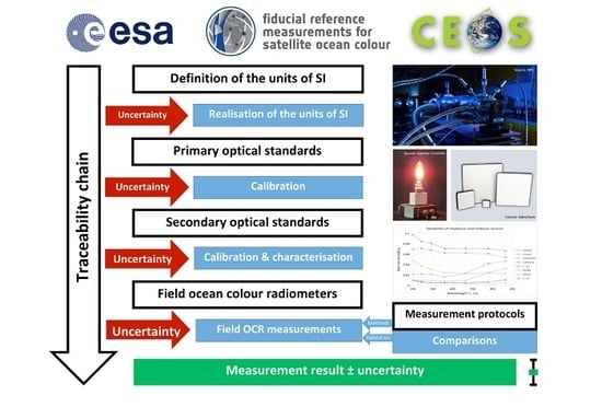


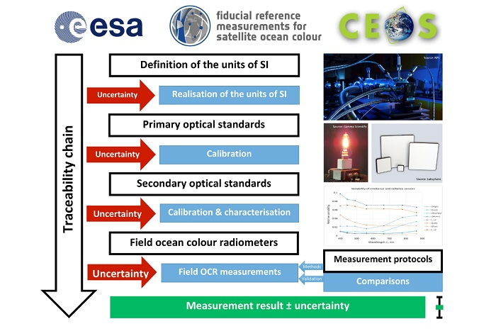
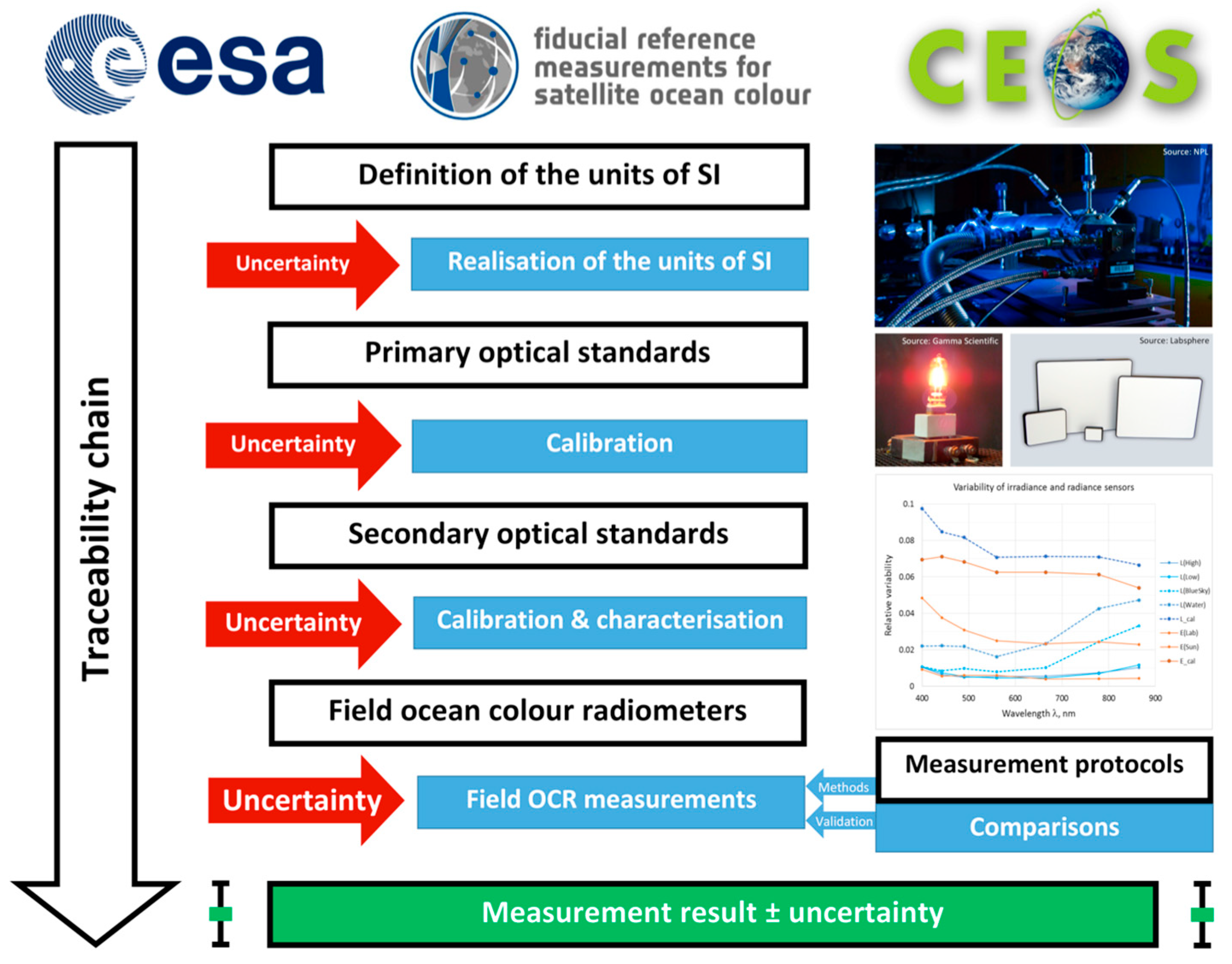
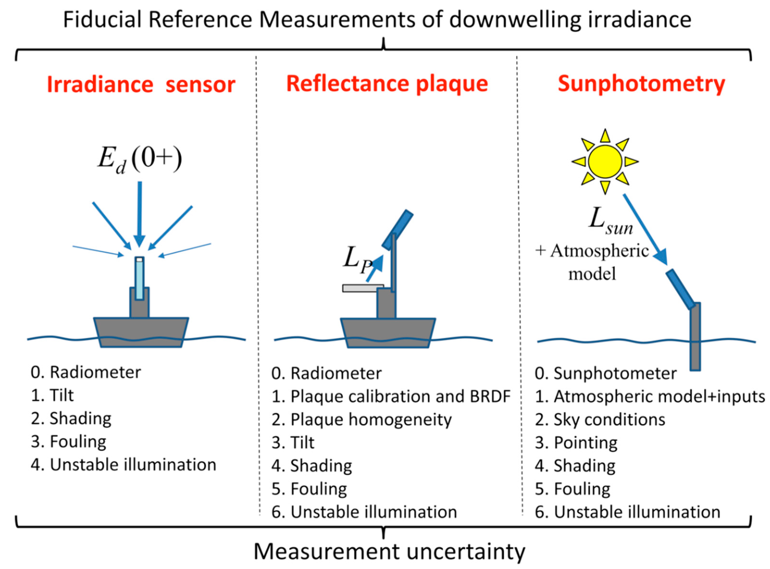
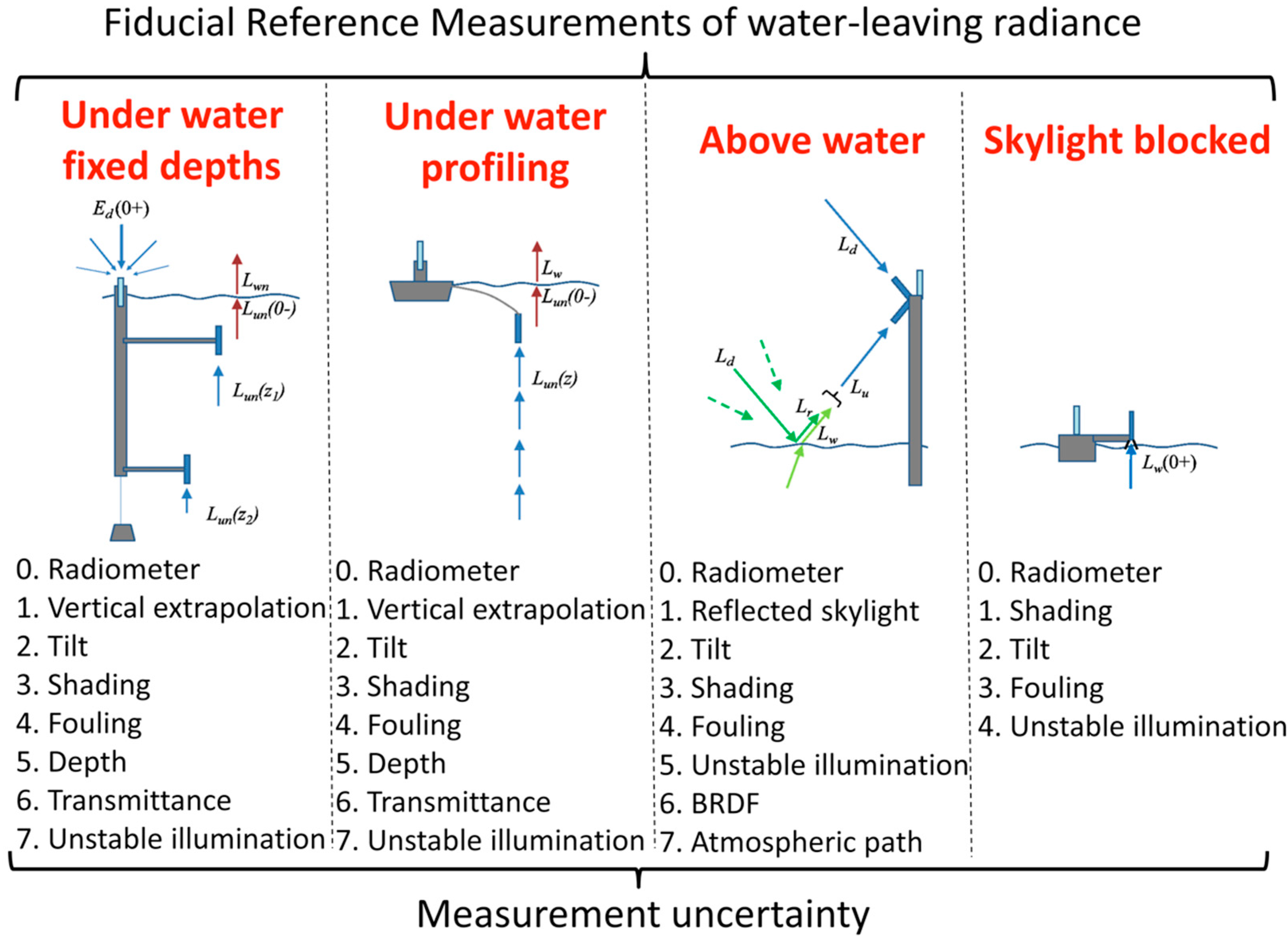
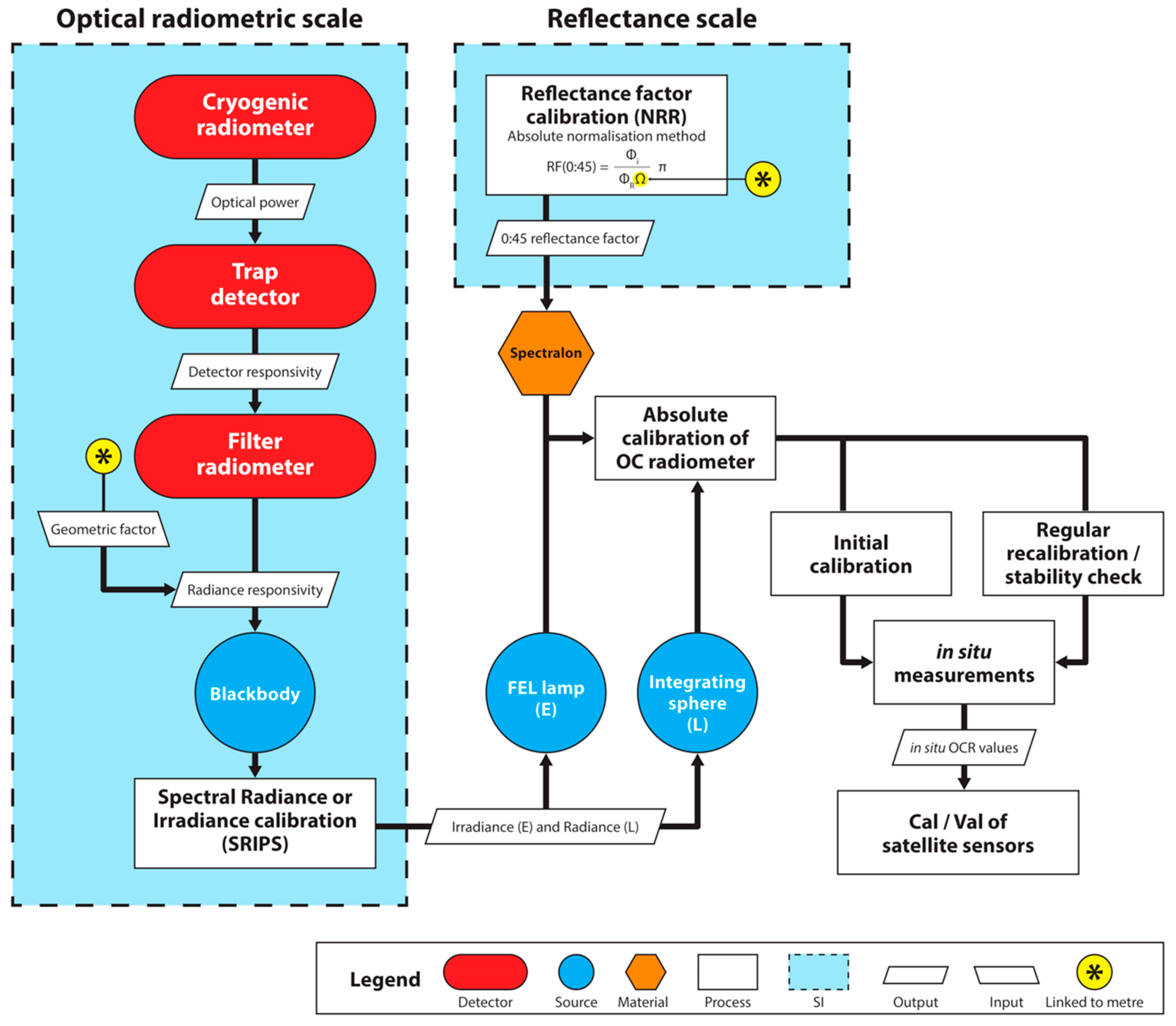
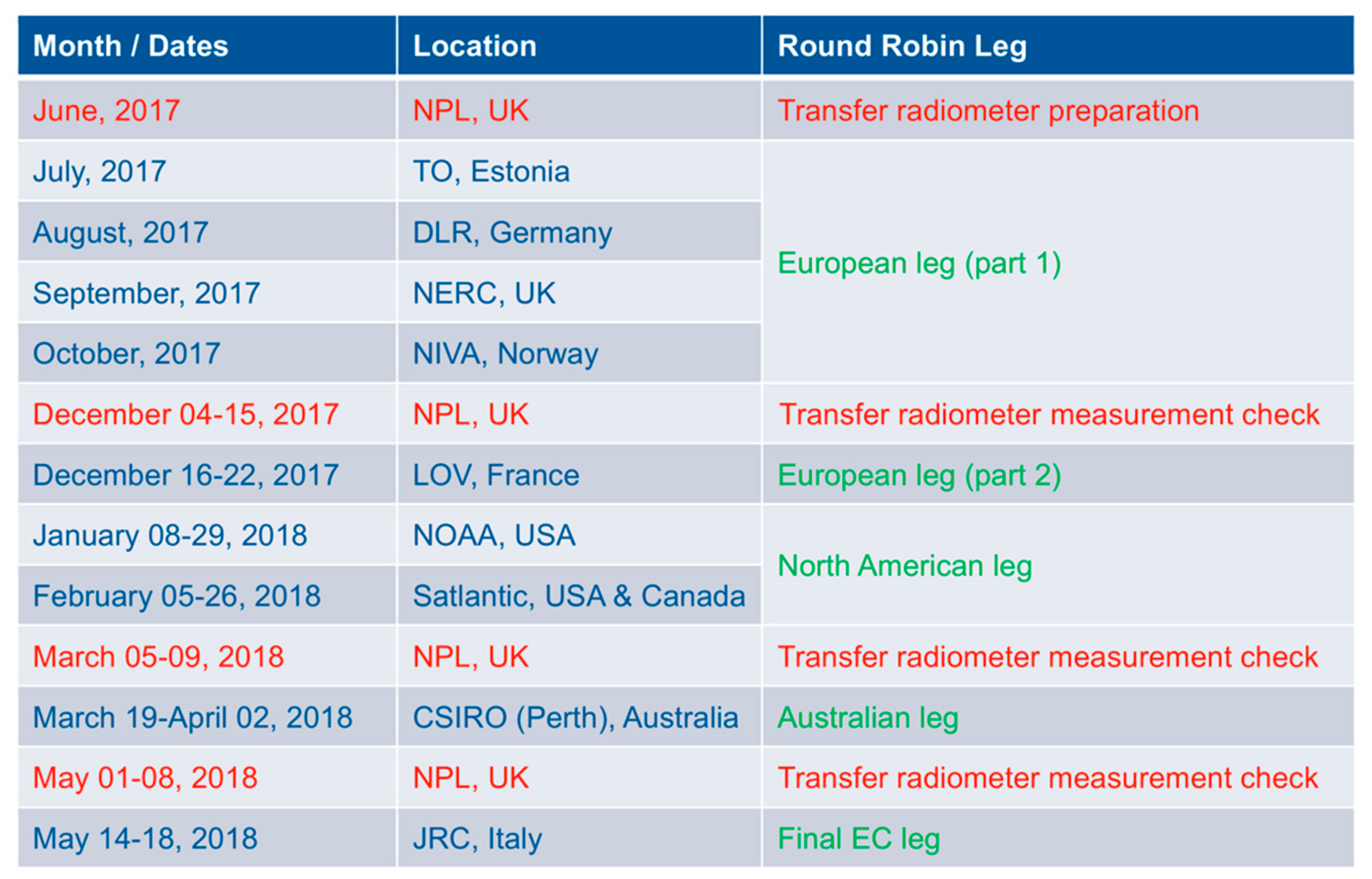
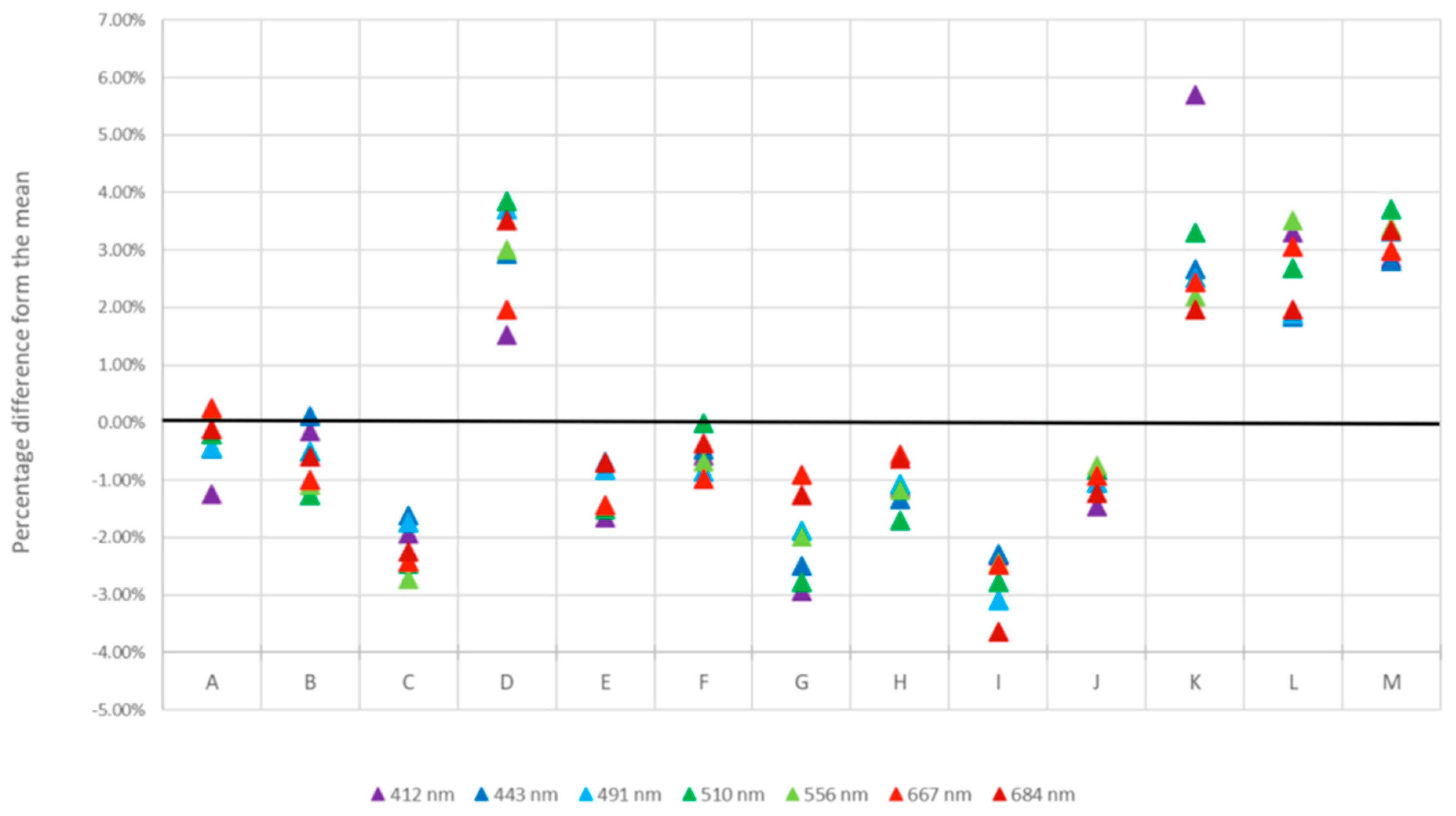
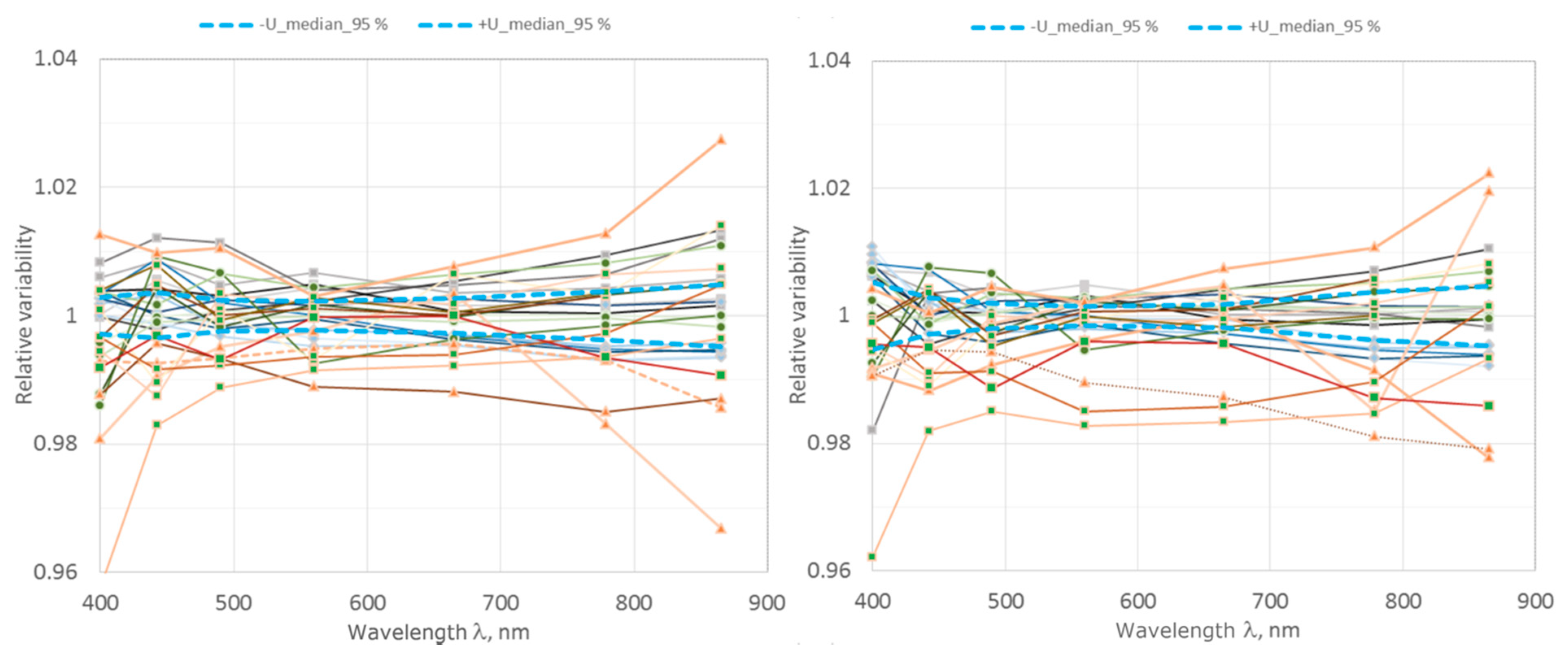
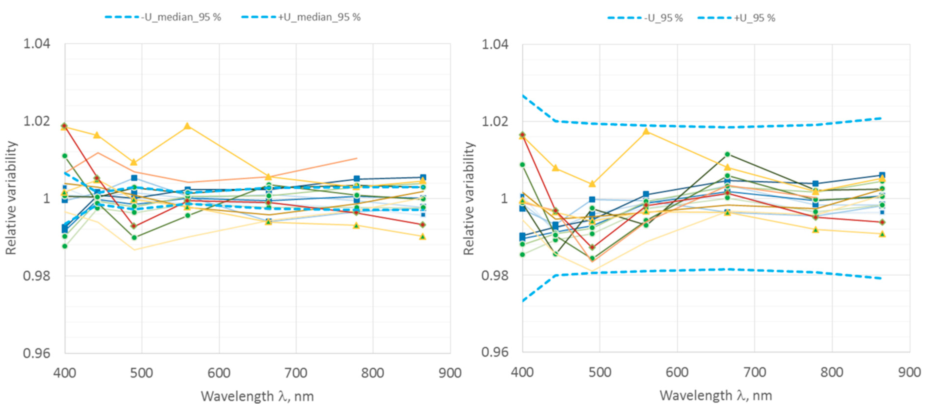
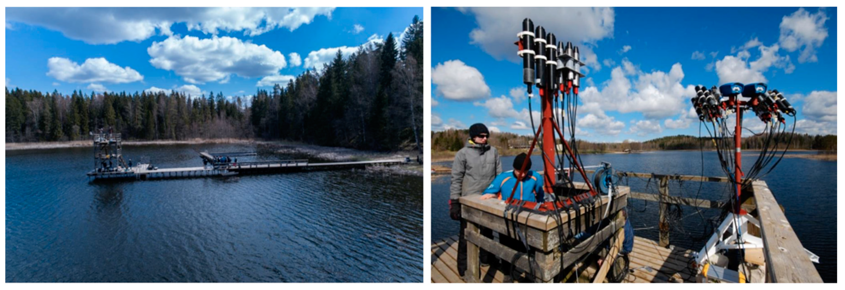
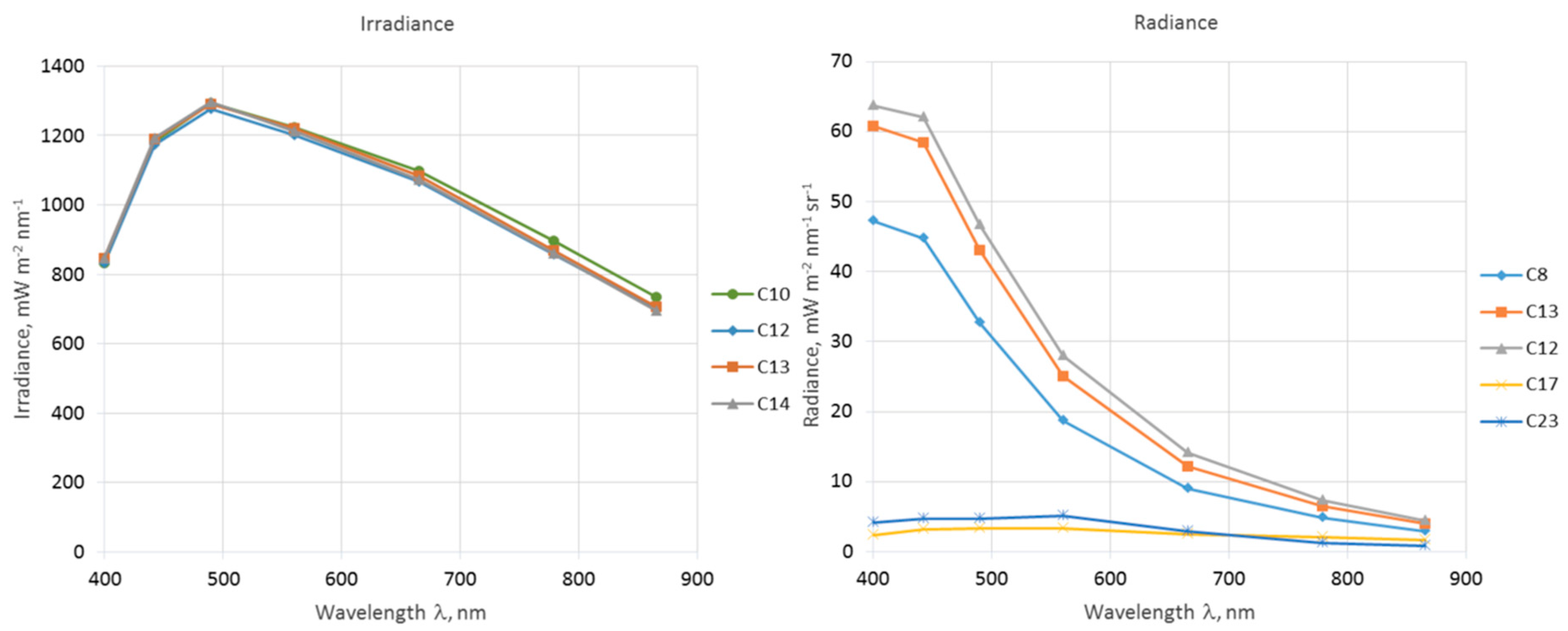
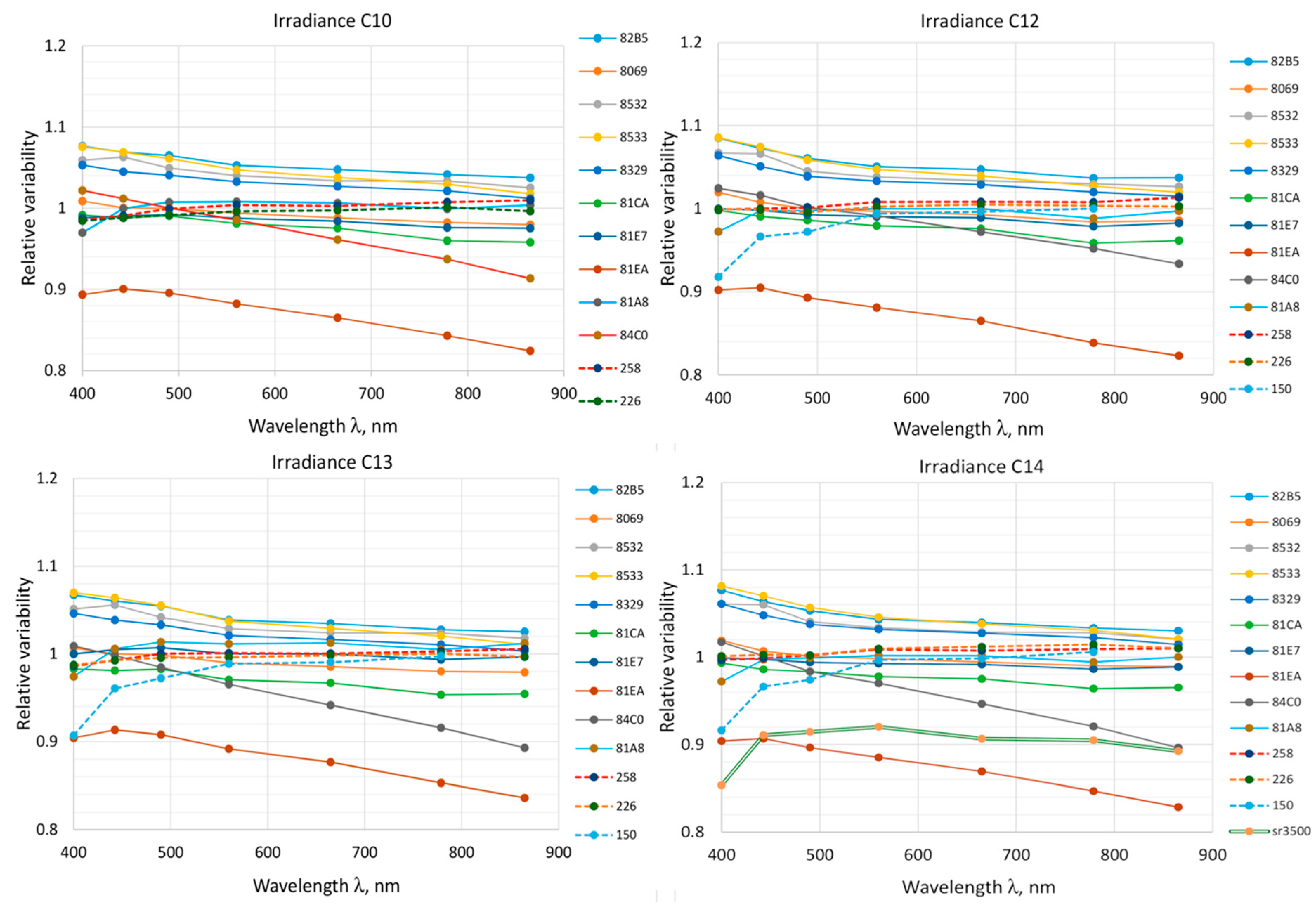
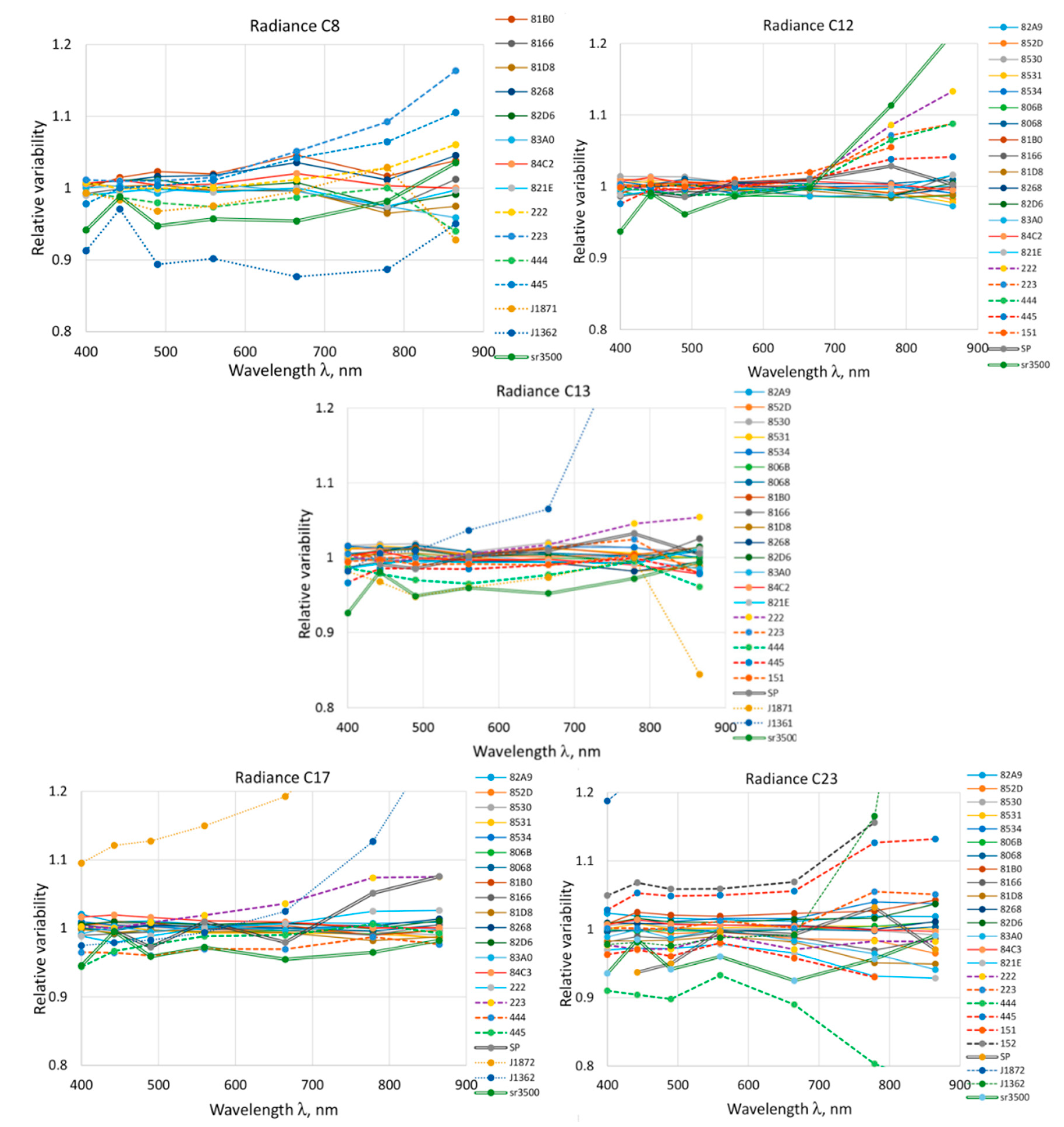
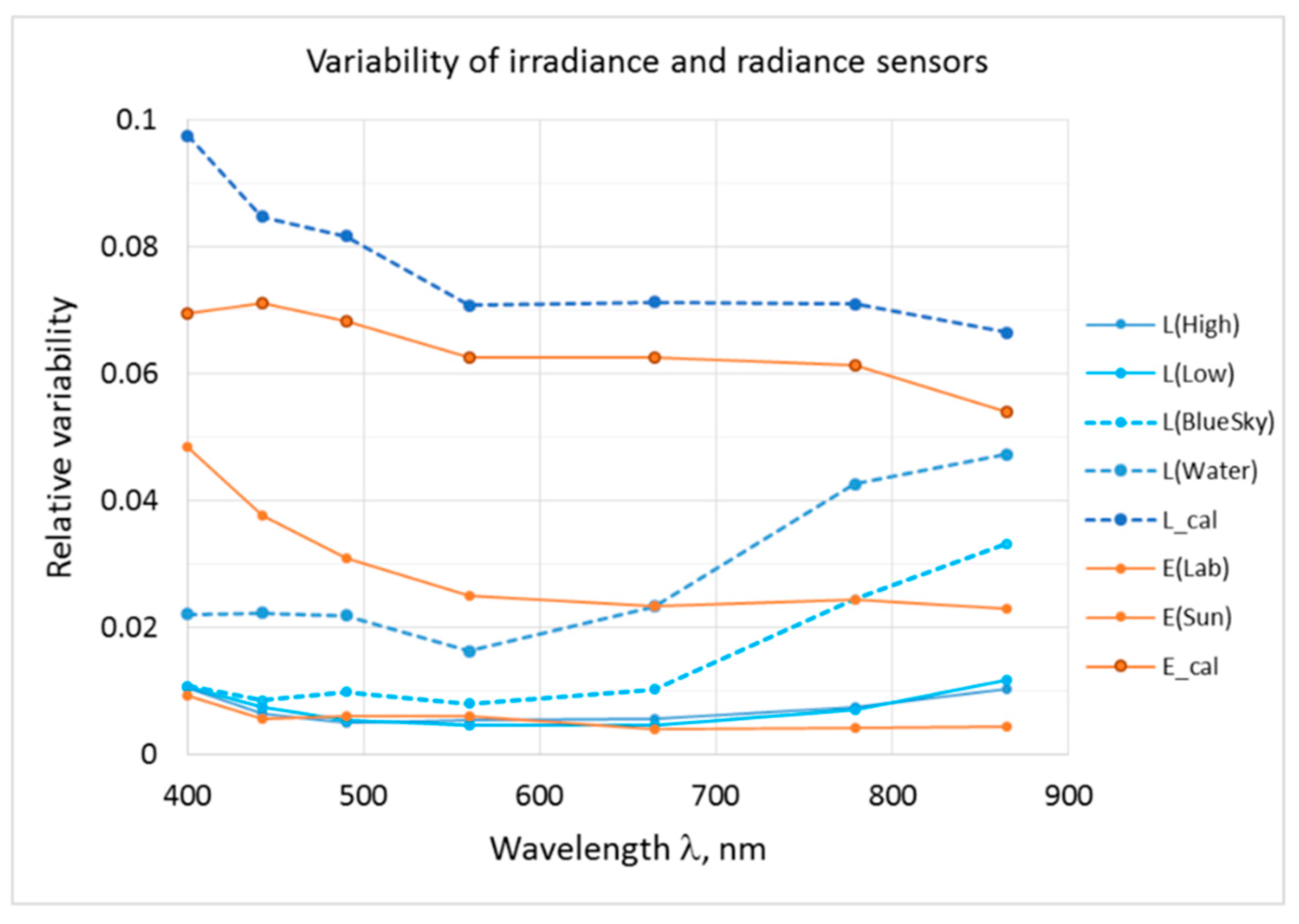
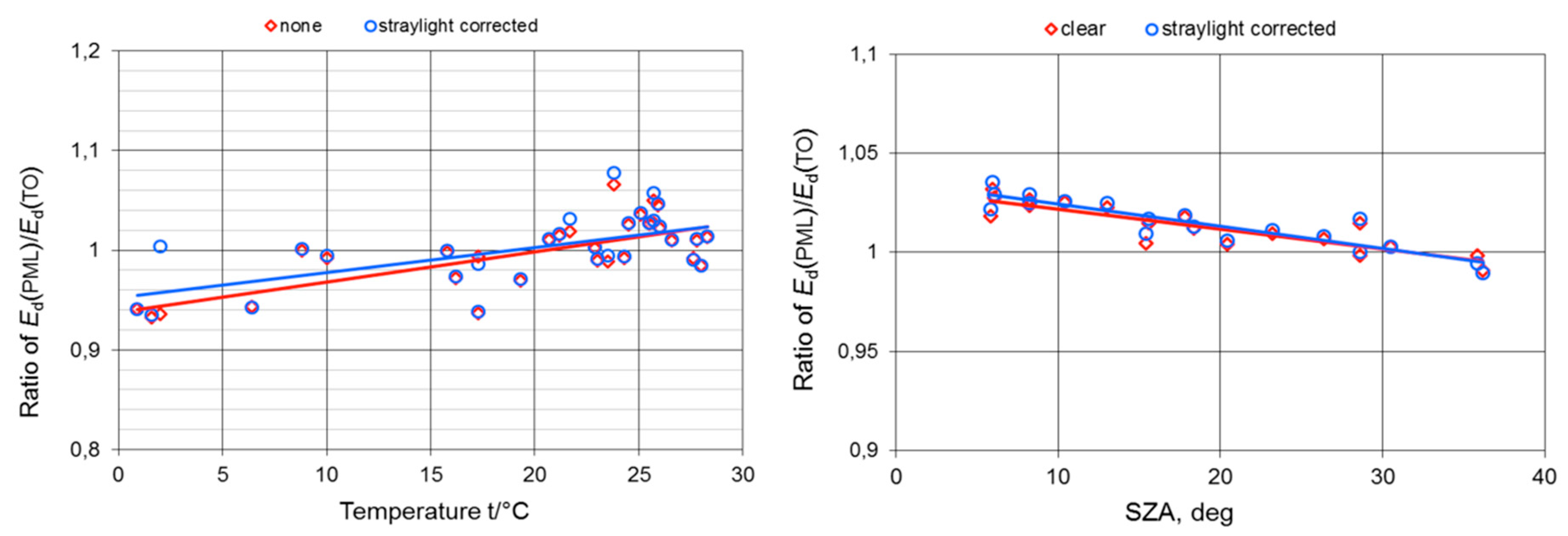
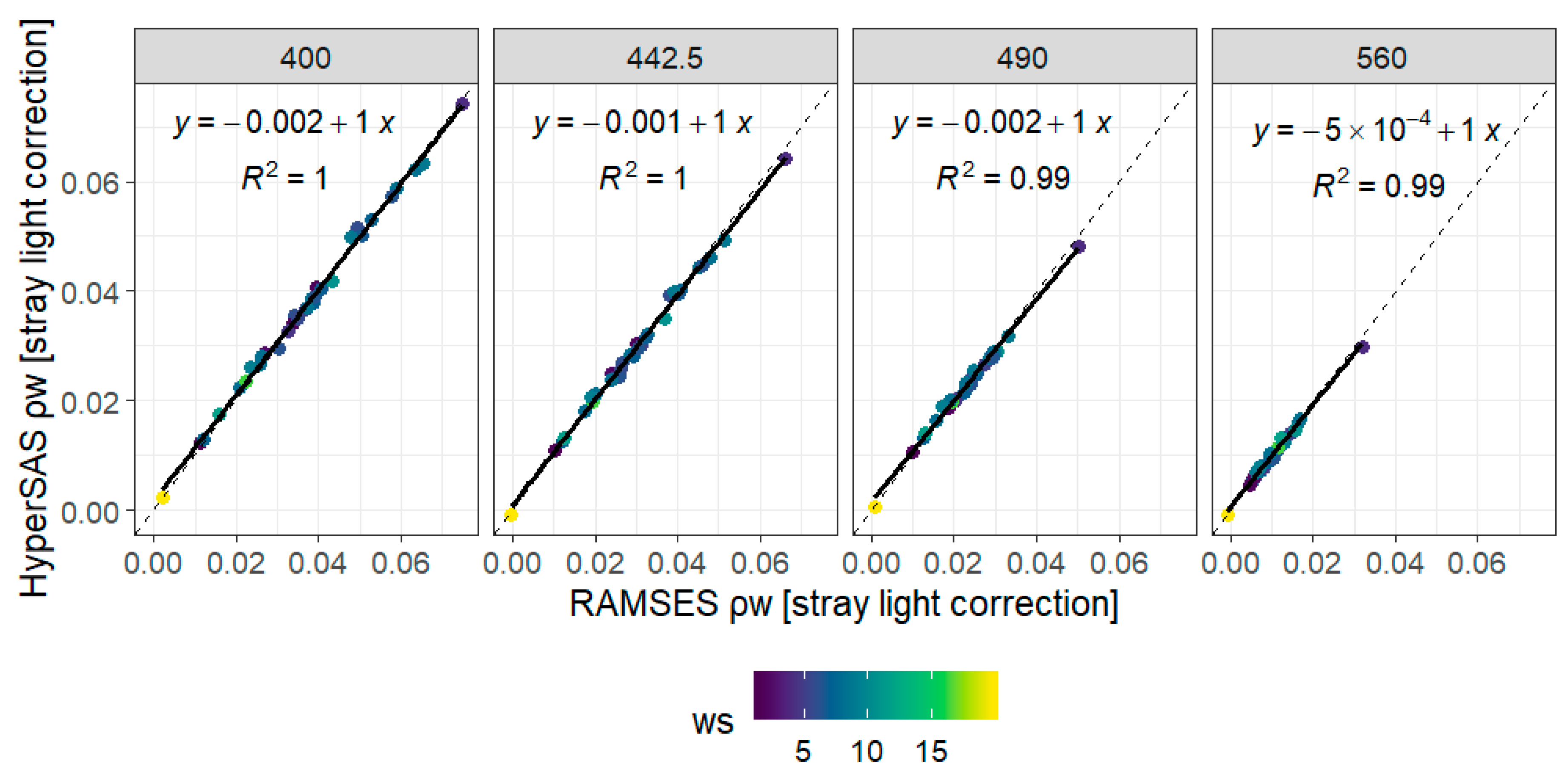
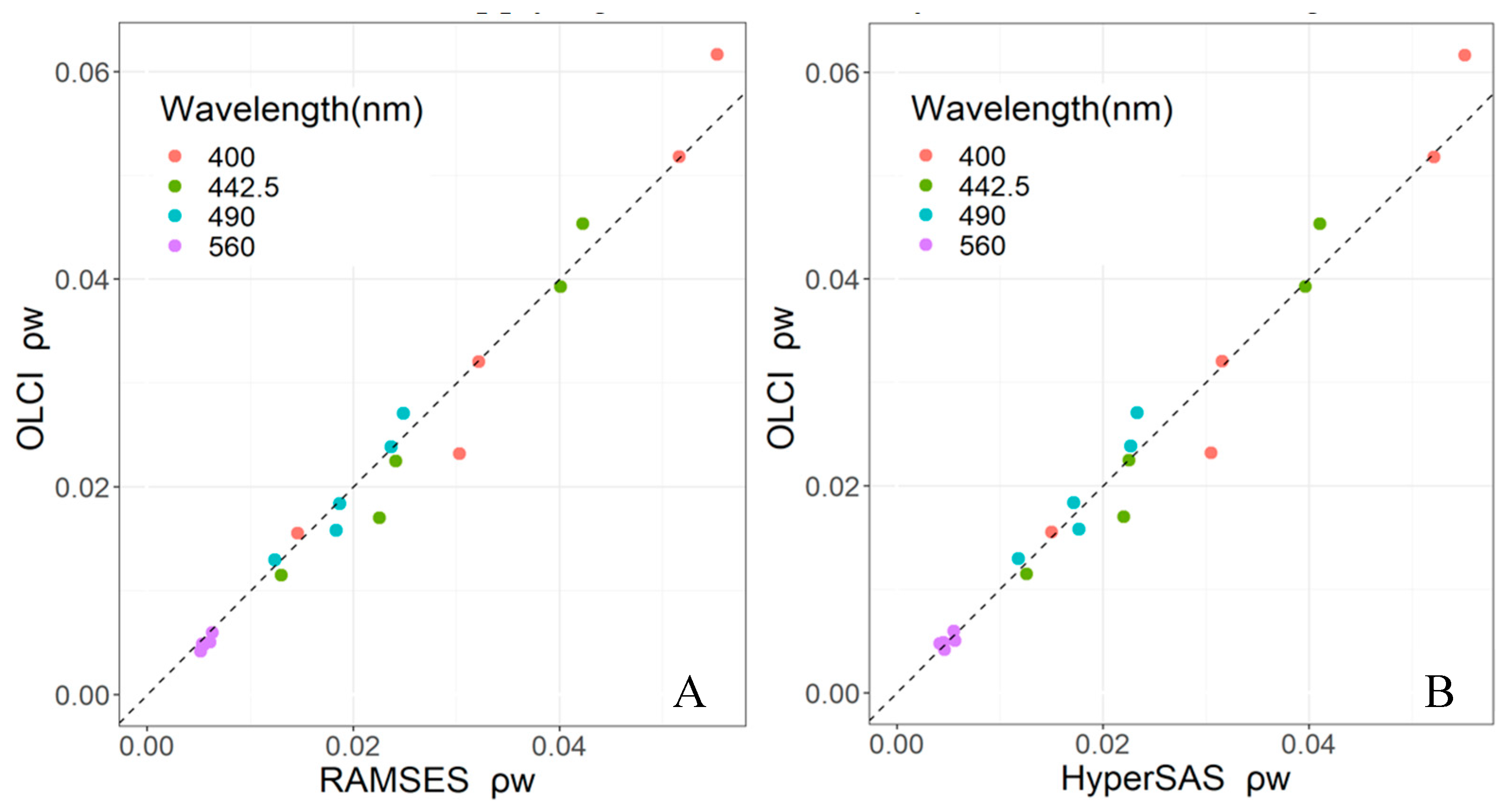
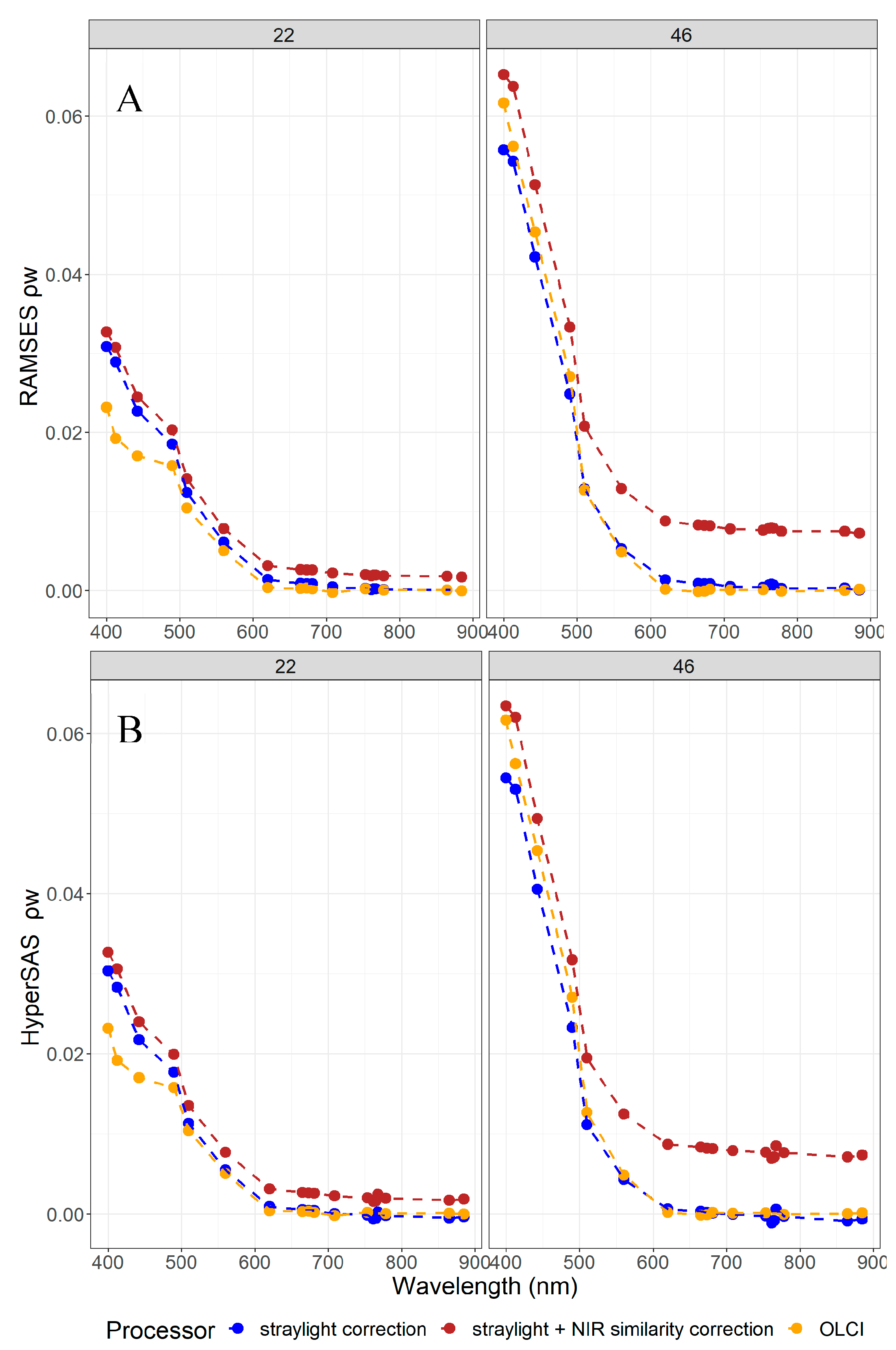
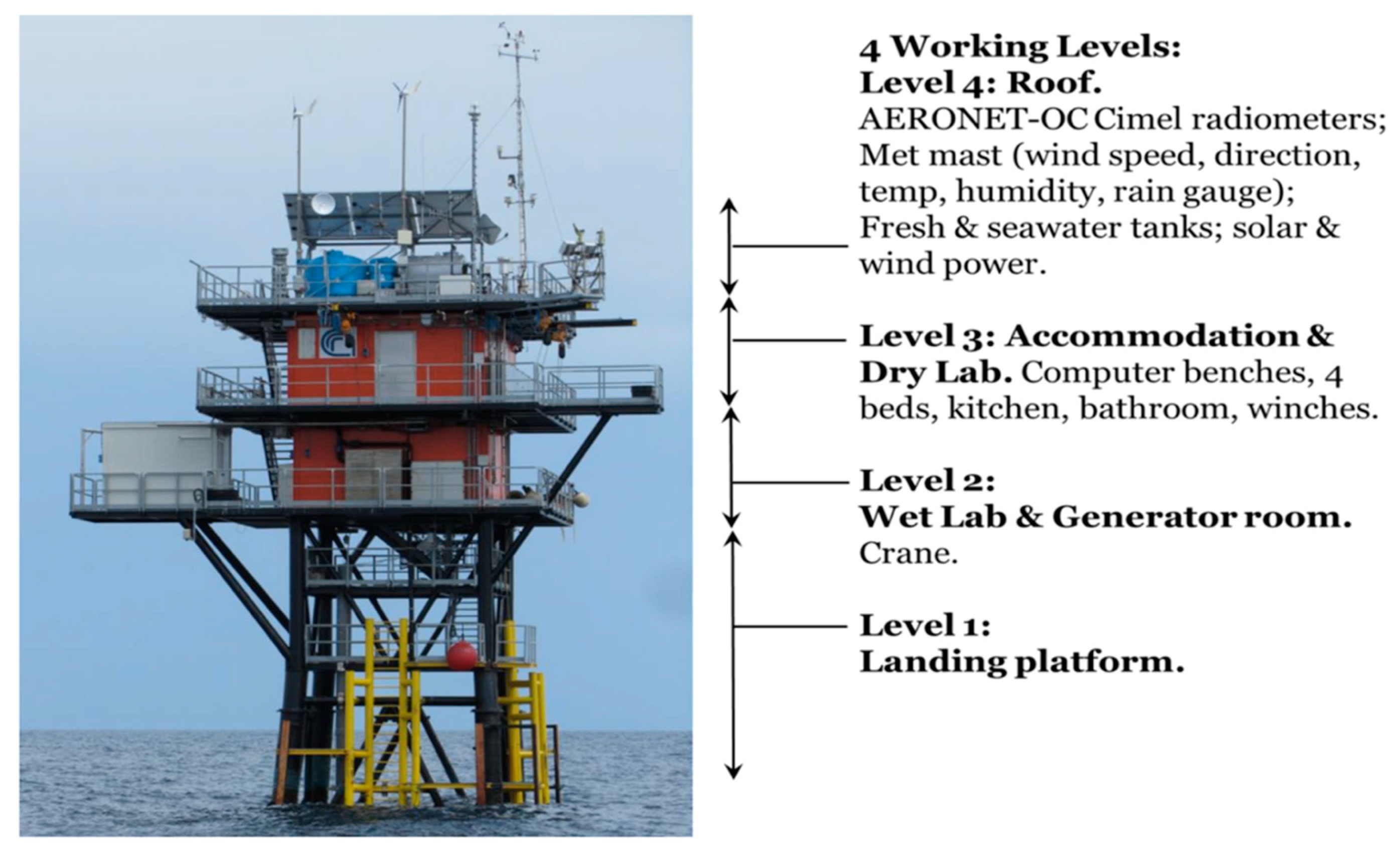
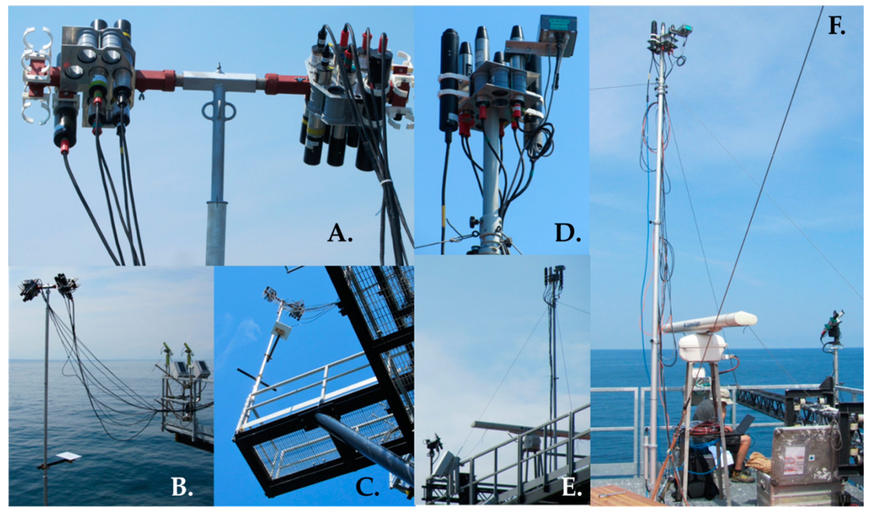
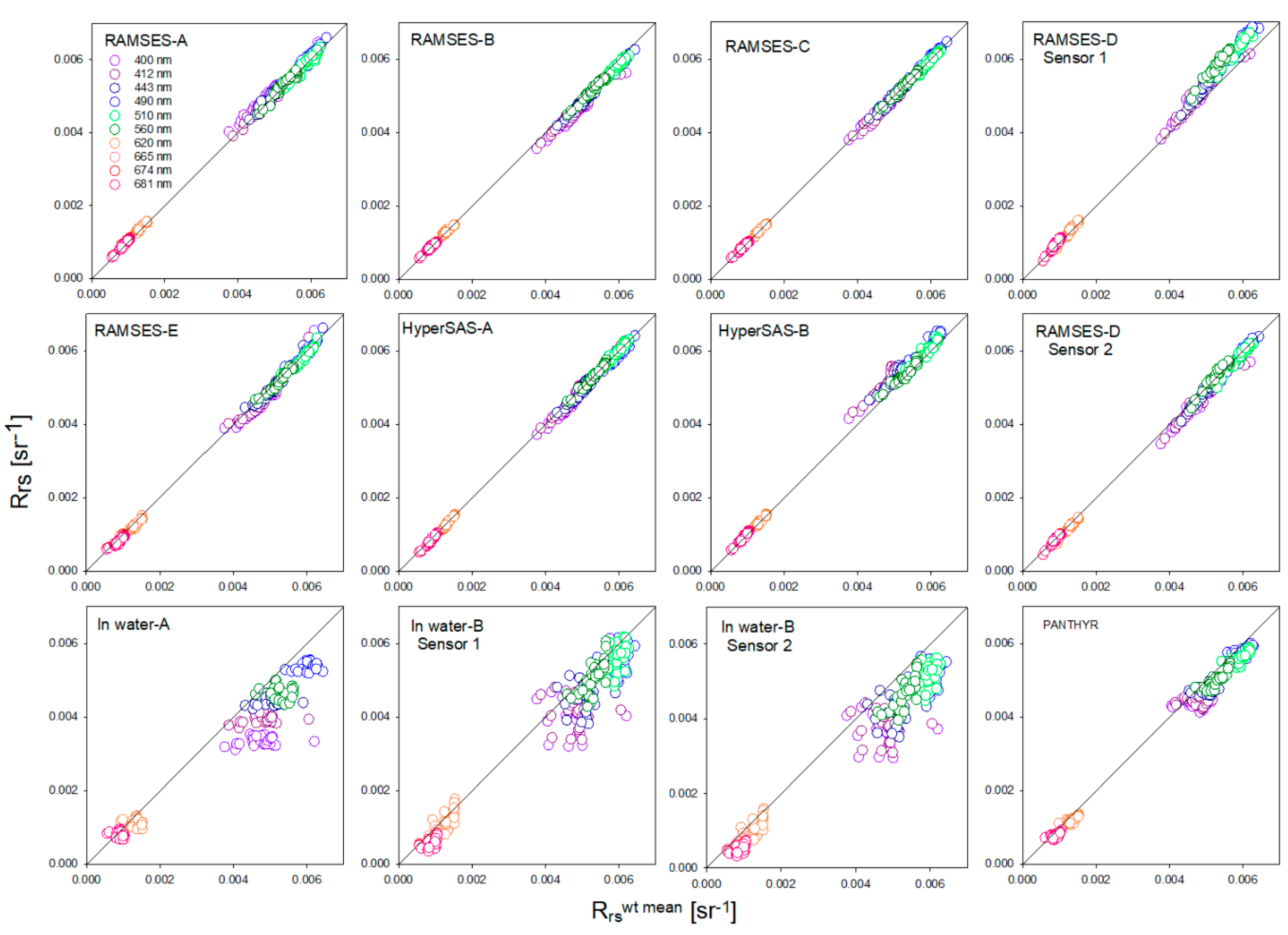
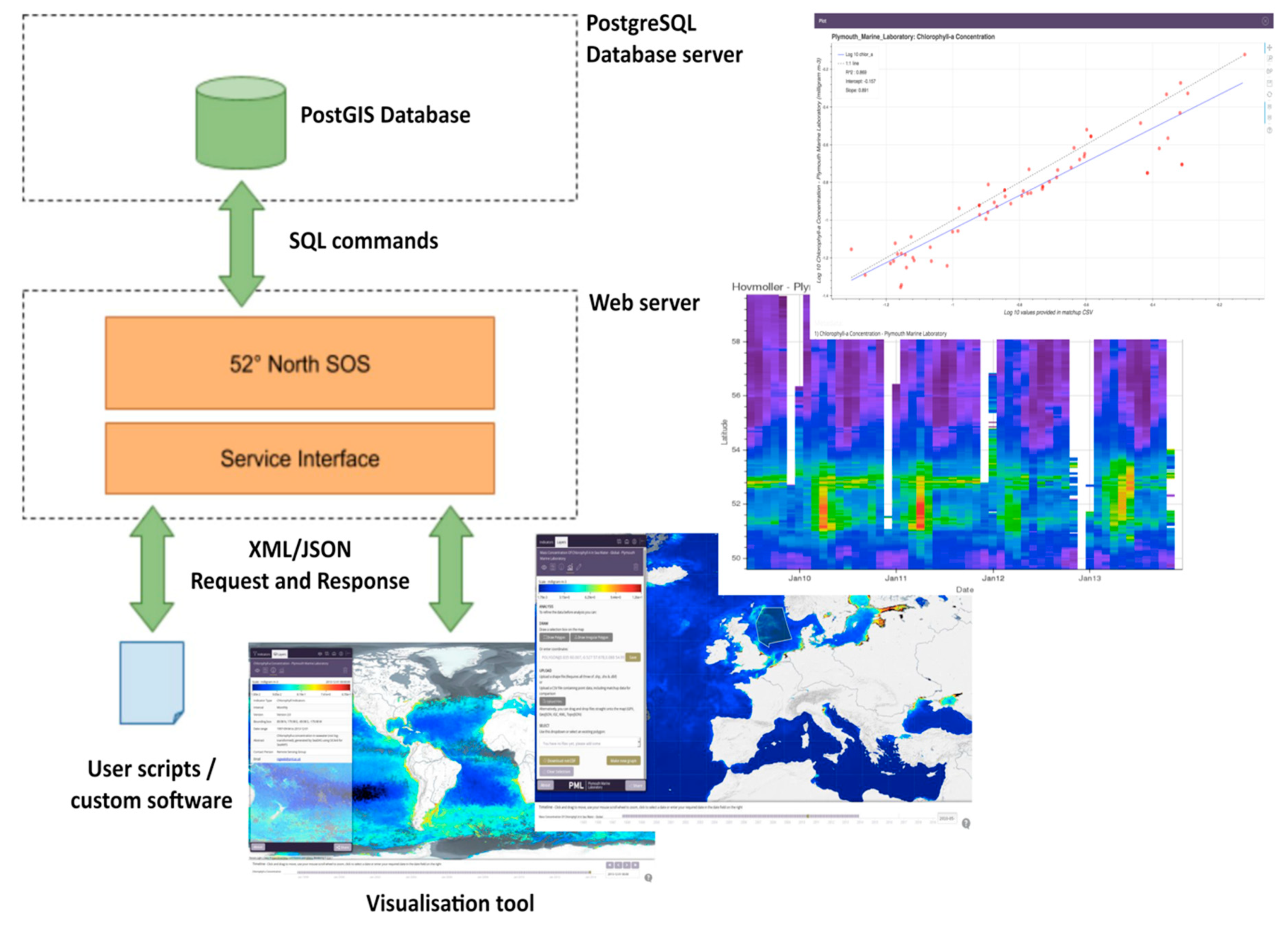
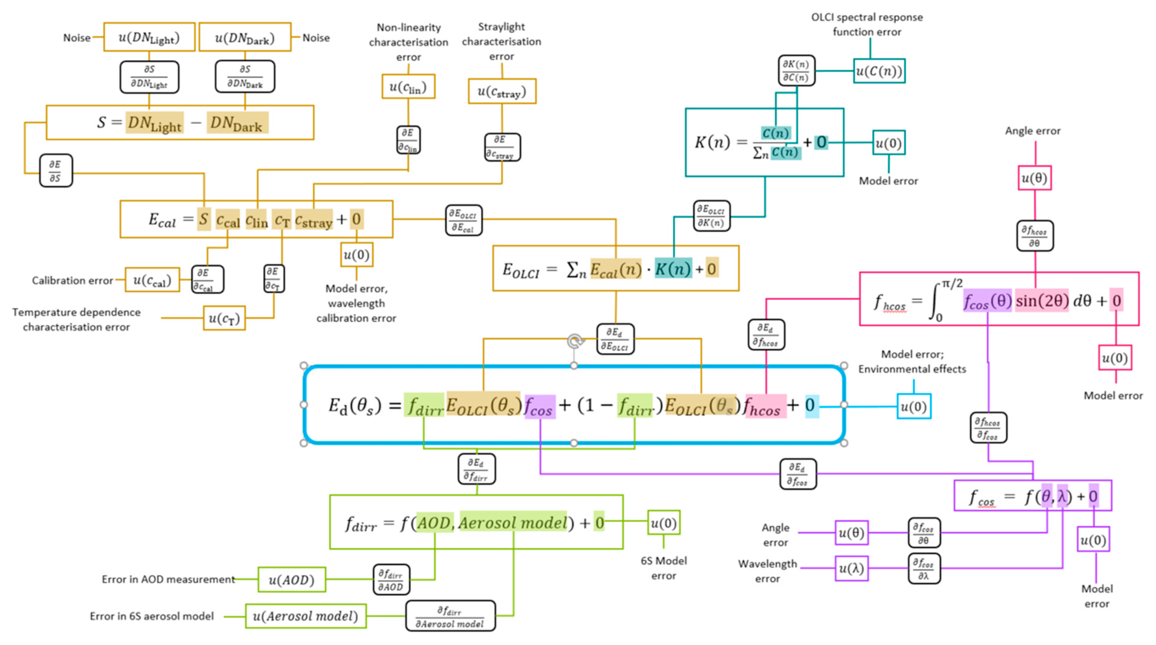
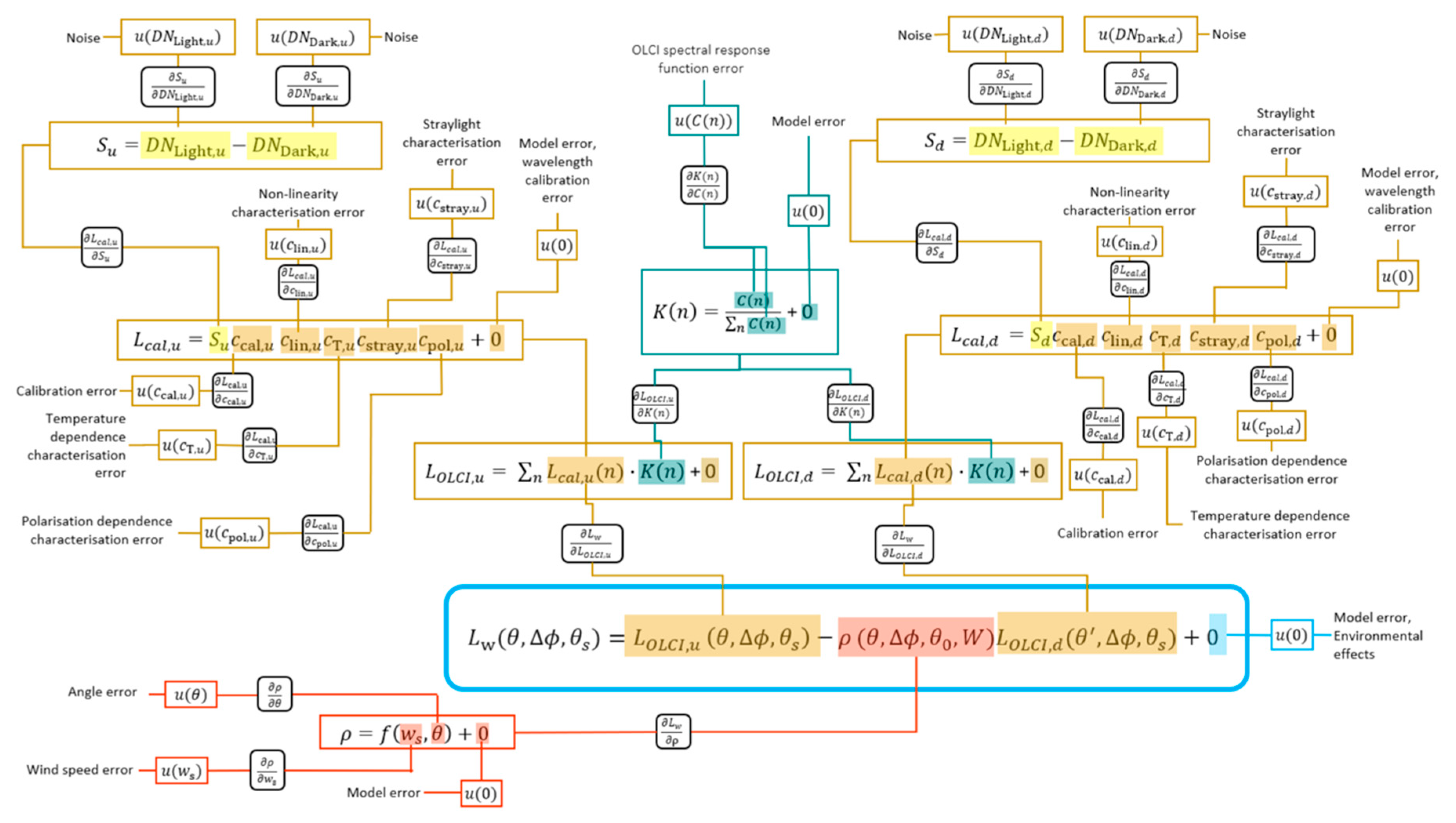
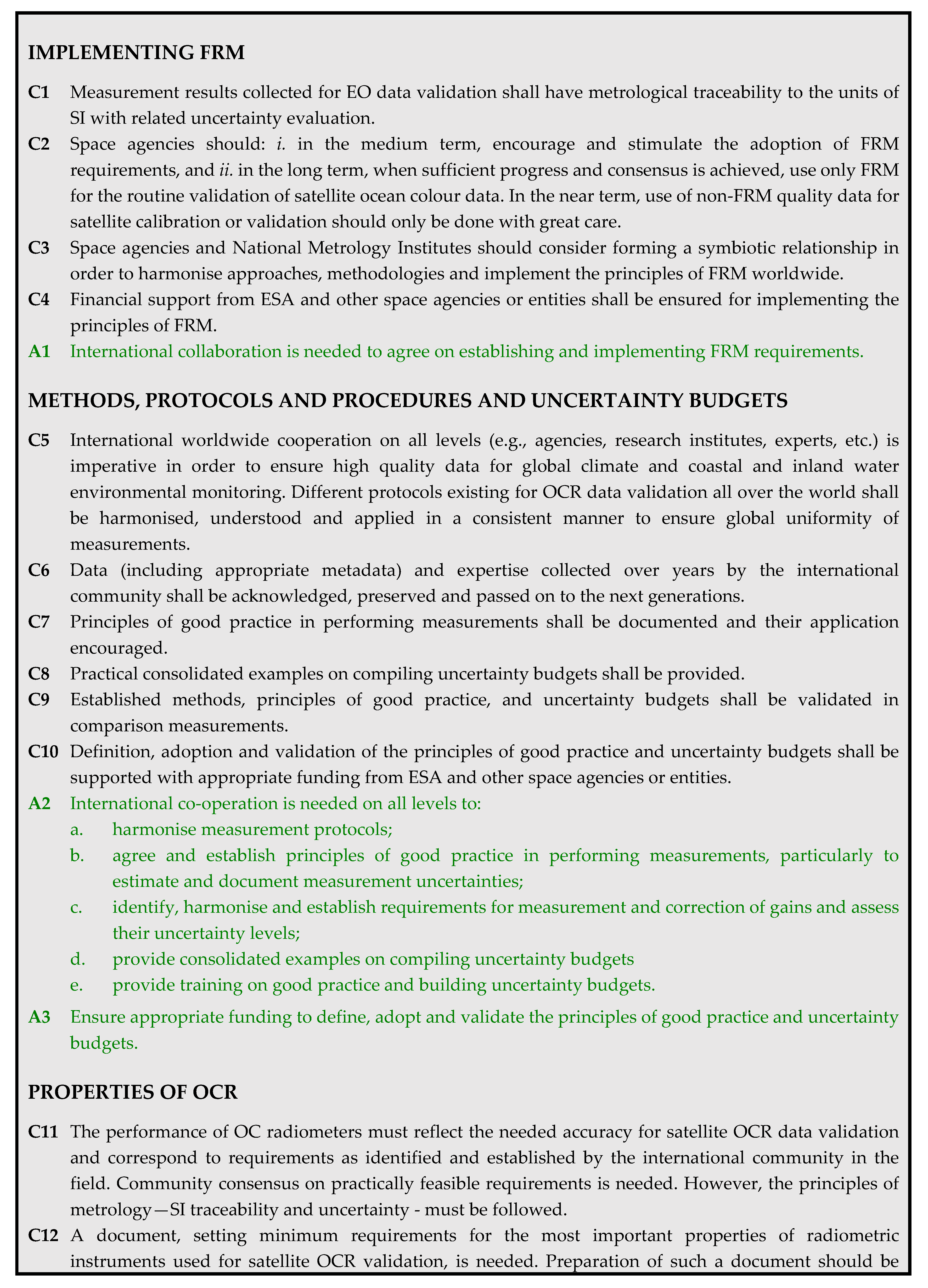
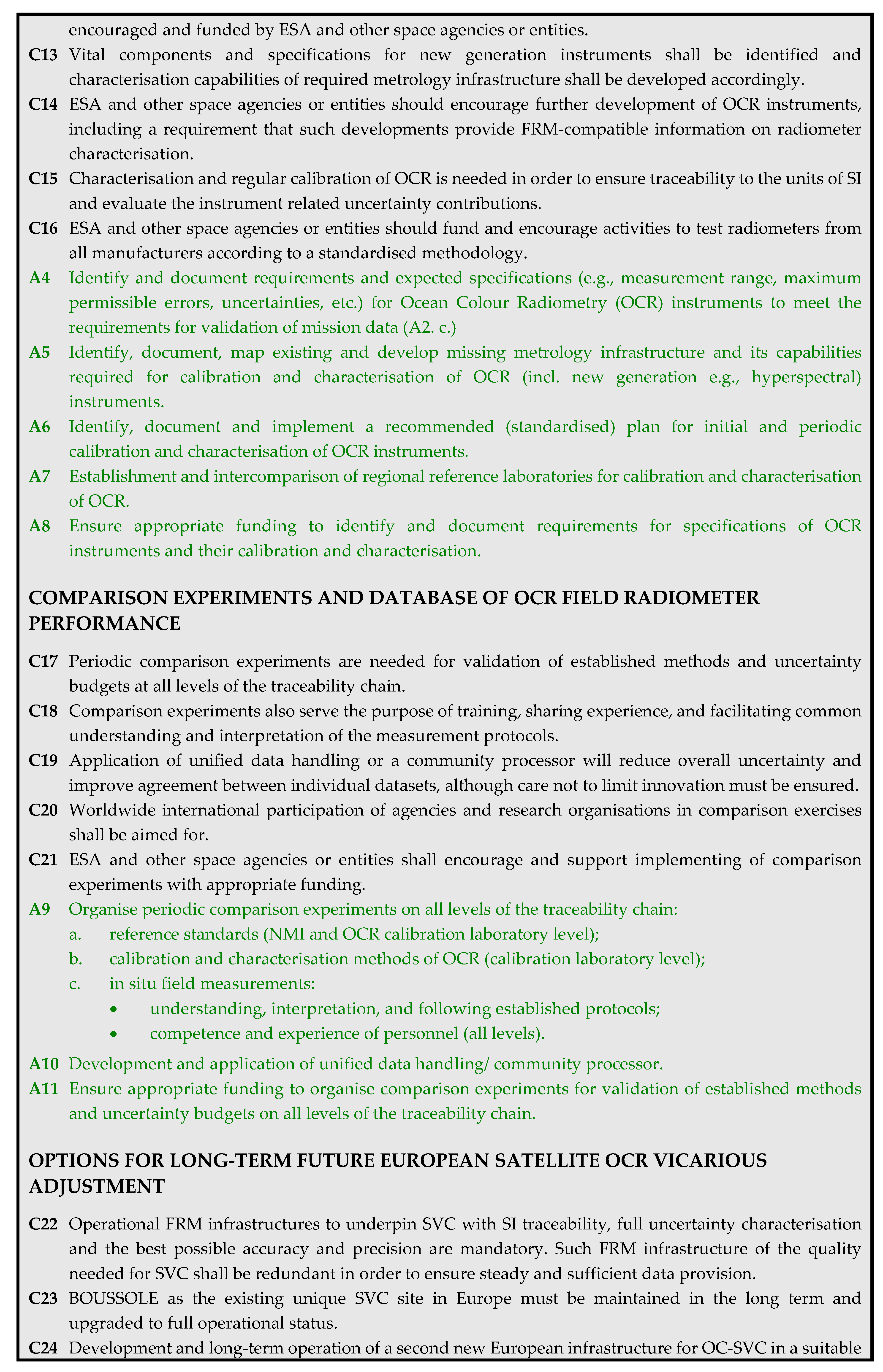
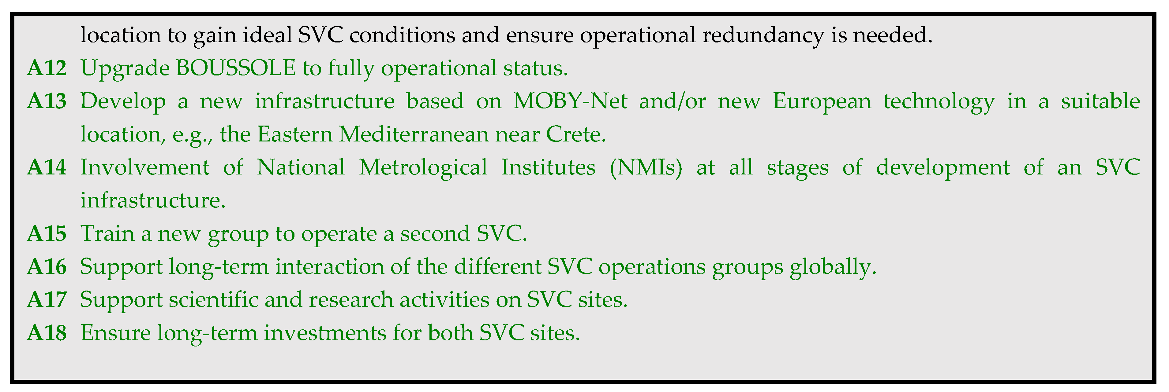