Abstract
The spaceborne mission TanDEM-X successfully acquired and processed a global Digital Elevation Model (DEM) from interferometric bistatic SAR data at X band. The product has been delivered in 2016 and is characterized by an unprecedented vertical accuracy. It is provided at 12 m, 30 m, and 90 m sampling and can be accessed by the scientific community via a standard announcement of opportunity process and the submission of a scientific proposal. The 90 m version is freely available for scientific purposes. The DEM is unedited, which means that it is the pure result of the interferometric SAR processing and subsequent mosaicking. Residual gaps, resulting, e.g., from unprocessable data, are still present and water surfaces appear noisy. This paper reports on the algorithms developed at DLR’s Microwaves and Radar Institute for a fully automatic editing of the global TanDEM-X DEM comprising gap filling and water editing. The result is a new global gap-free DEM product at 30 m sampling, which can be used for a large variety of scientific applications. It also serves as a reference for processing the upcoming TanDEM-X Change DEM layer.
1. Introduction
Digital Elevation Models (DEMs) are of fundamental importance for a large variety of scientific and commercial applications. Precise and up-to-date information about the Earth’s topography is required in many geoscience areas, such as geology, forestry, glaciology, oceanography, and hydrology. As an example, the availability of a reliable DEM represents a precious input for the assessment of hydrogeological risk or the estimation of damages in case of natural hazards, such as flooding events [1,2]. Currently, plenty of local DEM products are available at various spatial resolutions and vertical accuracy levels. They can be generated using different sensors, such as, e.g., airborne laser scanners (LiDAR) or optical stereographic imaging platforms. Good quality DEMs are commonly available over populated areas and developed countries, while for more remote regions only lower quality, large-scale/global products exist. Before the year 2000, global DEM products were generated by mosaicking data from different sources into a common grid, resulting in in-homogeneous quality. In 2000, the Shuttle Radar Topography Mission (SRTM) was launched [3]. It allowed for the acquisition of single-pass interferometric synthetic aperture radar (InSAR) data, covering about 80% of the landmasses for latitudes between 56 south and north. In 2003, the first nearly global DEM derived from SRTM data was published. It is characterized by a posting of 90 m and linear relative vertical accuracy of 10 meters (LE90). Several different edited versions have been generated from the original elevation data throughout the years, including gap filling with external references and water flattening. Since that milestone, other global/nearly-global DEM products have been generated from single sensors. For example, the Advanced Spaceborne Thermal Emission and Reflection Radiometer (ASTER, [4]) global DEM covers latitudes from south to north, with a pixel spacing of 30 m and horizontal and vertical accuracy of 20 m and 30 m, respectively, at 95% confidence level. The first version was released in 2009 and the third and latest one in 2019 [5]. Another global elevation model with better accuracy is the Advanced Land Observing Satellite (ALOS) DEM, derived from the Prism sensor data between 2016 and 2019 [6]. The posting is 5 m for the state of Japan and 30 m elsewhere. It was partially delivered in different versions with a typical accuracy below 10 m. Recently, the original SRTM data have been reprocessed and mosaicked to the NASADEM product [7], which has been officially released in February 2020. The result shows a significant improvement in terms of quality and coverage with respect to the previous SRTM DEM versions [8].
The global TanDEM-X DEM has been generated from bistatic X-band radar data, acquired between 2010 and 2015 by the two German twin SAR satellites TerraSAR-X and TanDEM-X [9]. It is currently the global single-sensor DEM product with the highest data coverage, including 99.89% of all the landmasses [10]. Such a DEM is the pure result of the interferometric processing and subsequent mosaicking of overlapping acquisitions. It has an independent ground resolution of 12 m and has been released in three different postings of 0.4, 1, and 3 arcsec, approximately corresponding to 12, 30, and 90 m, respectively. Moreover, it is specified with an unprecedented relative height accuracy for a global DEM product, which is under 2 m over flat areas at a 90% confidence level. Remarkably, the actual performance is far better than the specification, showing that 50% of the delivered geocells (extending by latitude/longitude) are characterized by a relative height accuracy under 1 m [10,11]. No further editing process has been applied, which means that water bodies appear noisy and residual gaps, caused, e.g., by missing data or geometric distortions, have not been filled. An example is presented in Figure 1. Up to now, a global edited version of the TanDEM-X DEM is only available for commercial customers of Airbus Defence & Space [12]. Limited to polar regions, a dedicated editing has been implemented in the framework of the PolarDEM project [13].
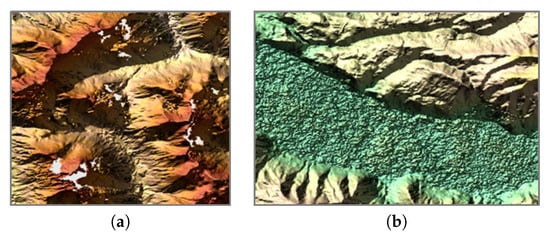
Figure 1.
(a) Example of gaps still present in the global TanDEM-X Digital Elevation Model (DEM) over high-relief terrain (white) due to geometric distortions in the original data (shadow and layover), (b) example of an unedited noisy water body.
The urgent need for an easily accessible edited version of the TanDEM-X global DEM for both scientific and data processing tasks, has boosted the development of a fast and wholly automatized editing procedure for filling gaps and flattening water surfaces.
In this paper, we describe in detail the editing algorithm, which is going to be applied to all landmasses except Antarctica. The latter has been excluded from the current version, given the availability of the PolarDEM. The fully automatic editing of the TanDEM-X DEM is performed at 30 m resolution in order to limit the computational load.
The paper is structured as follows. Section 2 describes all the developed algorithms for generating the TanDEM-X water-body layer (Section 2.1), classifying the different gaps before the edition (Section 2.2), filling gaps through diverse interpolation approaches (Section 2.3), flattening water surfaces (Section 2.4), and generating the final editing mask (Section 2.5). Section 3 presents exemplary edited DEM areas and discusses the final performance. Finally, the conclusions are drawn in Section 4.
2. Method
The DEM editing takes care of two main aspects: filling voids (0.11% of the landmasses) and flattening water surfaces. For this purpose, a dedicated framework has been designed in order to organize and optimize the processing steps. The high-level flow-chart of the automatic editing is depicted in Figure 2.
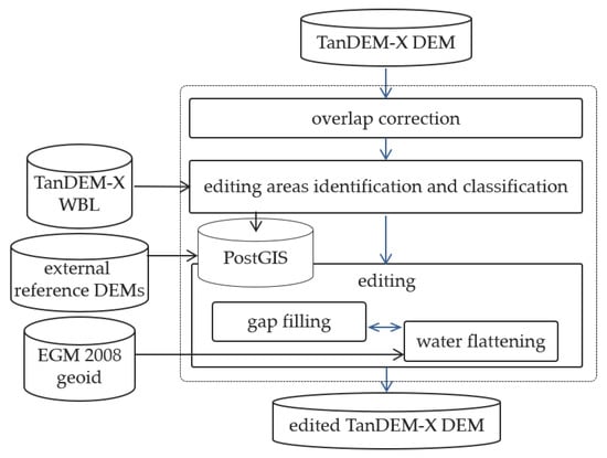
Figure 2.
High-level flow chart of the developed automatic framework for DEM editing.
Adjacent TanDEM-X DEM geocells are characterized by a single overlapping pixel, which is consistent most of the times. Nevertheless, in rare cases, overlapping pixels from two different geocells show height offsets, resulting from differences in the operational mosaic procedure. Therefore, the very first step of the entire processing chain is to equal such pixels by simply substituting them with their mean value.
Then, the areas to be edited are identified and properly classified in a subsequent step as detailed in Section 2.2. Here, the use of an external reference water mask is required. An important aspect to be taken into account is that such a map should be as timely consistent as possible with the considered DEM data, given the high variability of water surfaces in time. Unfortunately, the global water mask layer (WAM) [14] associated with the TanDEM-X DEM product is of insufficient quality to be used for editing purposes. In particular, geometric distortions are too often underestimated and misclassified as water bodies over high-relief terrain, and the use of this information would result in a wrong editing. For this reason, we developed an independent global water-body layer (WBL) from the same input data set of nominal TanDEM-X acquisitions, starting from the work introduced in [15], and utilizing a multi-looked quicklook version of the original full-resolution images, in order to speed up the processing time. More details on the TanDEM-X WBL are presented in Section 2.1 and an exhaustive description of the product will be included in a further publication.
After the classification of different types of gaps and water bodies, the true editing process begins, as detailed in Section 2.3 and Section 2.4. It consists of two independent modules that communicate with each other through a GIS database and can operate in parallel. Moreover, each module can also edit geocells in parallel, while areas identified to be edited within a single geocell are approached sequentially. Finally, an editing mask is generated pixel-wise, indicating whether the pixel has or has not been edited. In case the editing was applied, the editing mask carries information about which algorithm was applied, which external reference was used, and so on. More details on the editing mask are described in Section 2.5.
2.1. The TanDEM-X WBL
Water bodies typically appear as dark areas within the interferometric coherence, since the bistatic signal decorrelates almost completely. This aspect makes the coherence a reliable indicator of the presence of water on the ground. Therefore, for the generation of the TanDEM-X WBL, we rely on the coherence as sole input feature for performing the classification. In particular, for each input scene (covering an area of about 30 km × 50 km), we first compute the two-dimensional gradient of the coherence and then apply a Scharr transformation in order to highlight the gradient edges [16]. At this point, we apply the well-established watershed algorithm to the edge image to perform the segmentation [17]. The latter is a non-parametric contour detection method, which, starting from user-defined markers, treats pixels values as a local topography. It then floods basins starting from the markers, until basins attributed to different markers meet on watershed lines. Such markers, also called seeds, are here set by taking values of the interferometric coherence close to the theoretical bias. The output is a set of closed contour lines which delineates the borders between regions with different characteristics. The contoured regions where the water seeds were initially placed are finally identified as water bodies.
A critical aspect of this approach when applied to InSAR images, is the presence of geometric distortions, such as shadow and layover, caused by the side-looking nature of SAR acquisitions. In these cases, the coherence is strongly degraded, leading to possible misclassifications in the detection of water surfaces. This is one of the major issues of the WAM layer [18]. In order to overcome such a limitation, we improved the detection of these regions, by computing a more reliable shadow/layover mask, with respect to the one available in the TanDEM-X global product. The latter is obtained by back-projecting an external edited reference DEM (in this case SRTM) into SAR coordinates and then computing the illumination angles from the acquisition geometry [15]. Pixels identified as either shadow or layover are flagged as invalid and no further used. An example of single-scene water detection is presented in Figure 3, which shows, from top-left, the corresponding image of the interferometric coherence, the shadow and layover mask, the classified WBL image using the watershed algorithm, the TanDEM-X WAM, and the corresponding optical image from Google Earth. The accuracy improvement over mountainous areas of the WBL, with respect to the WAM, is clearly visible. Where the WAM misclassifies most of the shadow/layover regions as water (blue), they are correctly identified in the WBL.
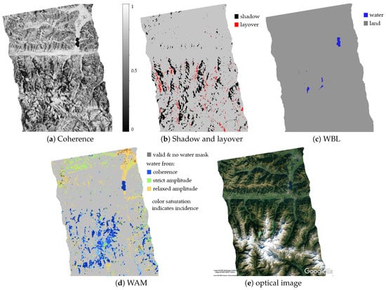
Figure 3.
Generation of the TanDEM-X water-body layer (WBL). (a) Coherence, (b) shadow and layover, (c) classified WBL, (d) water mask layer (WAM) layer (e) optical image from Google Earth.
Overlapping classified images are then mosaicked together by computing a weighted average, where quality weights are assigned depending on the reliability of the water detection. For example, acquisitions affected by heavy-rain clouds receive a reduced weight. On the other hand, acquisitions characterized by small orthogonal baselines are less affected by volume decorrelation with respect to acquisitions with larger baselines, and they receive an increased quality weight, since the probability of confusing water with decorrelated vegetation is lower.
An additional critical aspect which is carefully considered in the generation of the WBL is the presence of frozen water surfaces. The latter are characterized by high levels of coherence in TanDEM-X data. This phenomenon particularly affects data takes acquired during winter time over high-altitude mountainous areas or regions close to the Arctic circle, such as northern Canada or Siberia. This leads to a possible misclassification of water bodies, which has been mitigated by considering the following two aspects. On the one hand, frozen water is detected in each single TanDEM-X image, acquired in such regions during winter time, by thresholding high coherence levels and then considering them as additional water surface. On the other hand, during the mosaicking of overlapping acquisitions, data takes acquired during winter time are given a lower priority with respect to summer ones (i.e., if a summer acquisition is available, it will be considered more reliable). This combined approach significantly improves the final performance of the WBL over such critical areas. In any case, the reader should also be aware that frozen water bodies are an extremely critical aspect for water detection in the WBL product, but might not be as critical for the editing of the TanDEM-X DEM. This is due to the fact that the WBL we generated is derived from exactly the same input data set of the global TanDEM-X DEM. This is the ideal case, since we have the best possible consistency between the two products. This means, e.g., that an undetected frozen lake in the WBL will not necessary correspond to a noisy area in the TanDEM-X DEM. On the contrary, it will very likely correspond to a smooth, flat surface in the latter.
2.2. Identification and Classification of Editing Areas
For each input geocell, the editing areas identification and classification process consists in first segmenting and then classifying gaps and water bodies into one of the following six classes, in order to edit the areas with the appropriate algorithm:
- Solid Big: extended void area caused by missing acquisitions,
- Water: water identified through the reference WBL and small gaps with high probability of being part of the detected adjacent water body,
- Water side: gap neighboring a water body,
- Disperse: small gap located in the vicinity of other gaps of the same kind,
- Small: small isolated gaps,
- Tiny: isolated tiny gaps (maximum 4 pixels).
An exemplary geocell, where almost all classes are present, is shown in Figure 4. It corresponds to the N52W125 geocell, located in the west coast of Canada, east from Vancouver. It is a mountainous region stamped by inlets. Here, the missing acquisition tagged as solid big is clearly visible and an example of disperse gaps is also easily recognizable in the orange rectangle. The green rectangle shows a detail of an area classified as water. One can note that, at the border of the two extended water bodies, there are 3 isolated voids (red pixels). They are considered to be water with high probability and are therefore flagged as water for the automatic edition. Water side and small gaps are also well recognizable in the displayed image. Finally, tiny gaps are also present, even though it is not possible to recognize them at this image scale.
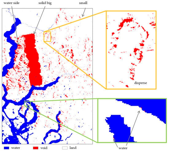
Figure 4.
Segmented void water image and associated classification tags as detailed in Section 2.2.
Moreover, gaps located in the vicinity (∼1.5 km) of the geocell border are tagged as such and, in case the gap continues in the neighbor geocell, it is merged with its neighboring counterpart, allowing for a smooth filling. The resulting merged geocells are then considered as a single one within the gap filling module.
In addition to gaps classification, also water bodies need to be classified, as different flattening algorithms are applied to oceans, lakes, and rivers. The classification approach described here focuses on the shape of the water body itself and is generalized in order to be applied at global scale. A dedicated algorithm has been designed to meet the specific characteristics of the TanDEM-X DEM and WBL. In particular, the WBL, as described in Section 2.1, is generated from TanDEM-X quicklook data with a ground resolution of about 50 m at the equator. This means that only rivers with a river bed wider than a resolution cell, i.e., 50 m, can be properly detected. Rivers characterized by a width close to the WBL resolution are mostly split into fragmented small pieces along the flow direction. In addition, also forests located nearby rivers are sometimes misclassified as water, given the low value of coherence caused by volume decorrelation. All these challenges, therefore, need to be considered.
The first and easiest water-body class to be detected is ocean. Most oceans cover at least one complete rim of the geocell. Hence, in such cases, the probability that the water body is an ocean is high and the water body is therefore flagged accordingly. There are only a few lakes in the world which are much larger than 100 km and stretch along a complete rim, like Lake Victoria in Africa, the Great Lakes in North America, and the Caspian Sea in western Asia. For smaller ocean areas covering only a corner of the geocell, the absence of a diagonally located neighboring geocell indicates ocean water. Again, only the few lakes mentioned before are so large that a diagonally located neighboring tile is not present. After detection, a region growing algorithm is used to extent the area of the ocean parts to the full ocean water body in the geocell.
The separation between rivers and lakes is far more challenging. Dedicated rules are defined to determine the probability for the water body to be a river. They include, e.g., the ratio between water area and the maximal extension of the water body or the ratio between its different extensions in latitude and longitude (or diagonal) direction. These rules are only applied when the area of the river/lake water body is larger than 100 pixels, which equals an area of about 100 m × 900 m at the equator for the 30 m resolution version of the TanDEM-X DEM considered here. Small torrents in mountainous areas are in general not detected by the WBL, as they have a river bed narrower than 50 m. Nevertheless, for larger rivers the gradient of the river bed is generally lower than 1 m/km. Hence, even if these small river pieces are classified as lakes, the water surface height is still precise enough for an effective surface flattening. On the other hand, also small lakes could be misclassified as rivers. This means the flattening procedure takes more time and leads to variations in the order of one meter in the flattened water surface. However, the variations are small and do not affect the processing of DEMs like the ChangeDEM layer. Finally, if a water body is detected neither as ocean nor as river, it is then simply classified as lake. An exemplary classification result is shown in Figure 5. The ocean is depicted in petrol, while lakes are marked in light blue, and rivers in cyan.
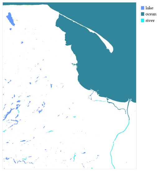
Figure 5.
Example of the classification around Gdansk, Poland with the ocean Baltic Sea in petrol, the lakes, e.g., of the Pomeranian Lakeland in blue and the river Vistula in cyan.
After the identification and classification of gaps and water bodies has been completed, the real editing procedure begins. The gap filling module starts with the edition of gaps crossing the border between two or more geocells, while the water flattening module starts by editing water bodies where no gap is present. Afterwards, the gap filling module edits the water side voids, enabling the detection of a precise shoreline. Once the shorelines are available, the water flattening module can finally process the remaining water surfaces within the geocell. All other segmented areas are processed afterwards.
2.3. Gap Filling
The gap filling module automatically manages the choice of the most appropriate editing method for void areas. Two different approaches are considered in order to interpolate missing data, as resumed in Figure 6:
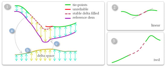
Figure 6.
Gap filling approaches: (1) interpolation where external reference DEM is available using a co-registered external reference DEM (purple) trough the following steps: (a) valid delta map (turquoise), (b) gap interpolation on the delta space (yellow), and its low-pass (orange) (c) is finally added to the reference to get the filled value (bordeaux). DEM reliable pixels are depicted in green. (2) and (3) are interpolation without an external reference (2) small isolated gaps: linear, (3) others: inverse distance weighted interpolation.
- If an external reference DEM is available for the considered region, all different types of gaps are filled by ingesting the reference into the missing areas. In this case, we implemented a stable method based on the delta surface fill interpolation [19]. The principle is that the considered area is composed by the bounding box of the gap to be filled, plus an adequate margin to anchor the reference to the input DEM (see Figure 6(1a)). In the following two subsections, we detail which kind of external reference DEMs are used together with their prioritization (Section 2.3.1), and we provide a more extended description of what we call the stable delta surface fill method (Section 2.3.2).
2.3.1. External Reference DEM Data
For the use of external reference DEMs, we rely on a large variety of data, acquired using different sensors (e.g., LiDAR, radar, and optical). All reference DEMs are indexed in a PostGIS database, and the selection process is completely automatized. For each gap and a surrounding margin, which is described in the next subsection, the module searches for all available references within the database and sets a priority level depending on the height accuracy of the product and on the type of sensor. Typically, local airborne LiDAR DEMs are characterized by very good performance in terms of accuracy and ground resolution. Moreover, the delivered products are almost gap-free, since airborne campaigns can be easily scheduled in order avoid surveys during thick cloud coverage. This makes them the privileged source of external reference data, in particular over mountainous regions. Here, SAR-derived DEMs typically suffer from severe geometric distortions, caused by the side-looking acquisition geometry, which degrade their vertical accuracy and often lead to invalid values (e.g., over shadow-affected areas) [10,20,21]. Differently, optical stereographic DEMs often present remaining gaps caused by the presence of persistent cloud coverage during data acquisition [22,23]. Unfortunately, high-quality LiDAR DEMs are not globally available. In particular, remote regions in developing countries are only seldom acquired, and we have therefore to rely on other global references to fill TanDEM-X DEM gaps over such areas. Specifically, we utilize the following products, which are here listed in decreasing priority order. If the highest priority reference is not available or presents invalid values, the sequence is spanned until the best valid reference is found, and then used for the stable delta surface interpolation. Starting from the highest priority, we have (1) Local LiDAR DEMs (e.g., [24,25]), (2) SRTM DEM (reprocessed data included in NASADEM [26]), (3) ALOS DEM only from Prism sensor [27], (4) NASADEM without GDEM, (5) ALOS DEM without GDEM, (6) NASADEM, (7) ALOS DEM. Moreover, all utilized reference DEMs are open source and therefore not subjected to any restriction of use.
Furthermore, the reader should also be aware that the external reference data could have been acquired during different time periods with respect to the TanDEM-X DEM. This aspect has got several implications when utilizing the edited DEM for multi-temporal applications, such as, e.g., DEM differencing for glaciers mass balance or mining activities monitoring. This is why additional information about the external reference DEM, which is used to fill gaps, is directly provided to the user through an additional layer, as explained later on in Section 2.5.
2.3.2. Stable Delta Surface Interpolation
The delta surface fill method replaces a DEM gap with an appropriate reference source, which is adjusted to the input DEM values found at the void interface [19]. Specifically, the delta surface is defined as the difference between the DEM to be edited and the resampled external reference on the same grid and vertical datum, computed over a larger area with respect to the considered gap. This methodology was first applied for editing the SRTM DEM and soon became a state-of-the-art method for DEM editing. It shows good performance when applied to moderate-relief terrain, while, over mountains or rough surfaces, its accuracy typically decreases, since the adjustment to the border pixels becomes more difficult.
The method used in this work for editing the TanDEM-X DEM is schematized in Figure 6(1a) and includes two main improvements with respect to the original delta surface interpolation, which aim at improving its robustness and stability. In particular, the external reference DEM is now anchored to the TanDEM-X DEM over specific tie-points only, selected by discarding unreliable pixels. The latter are, e.g., pixels strongly affected by geometric distortions or by low coherence. In Figure 6(1a), tie-points are shown in green, while the union of all unreliable pixels (in red) form what we call the unreliable mask.
Pixels belonging to such a mask are treated as if they were voids, and are shown in yellow.
Such a mask is derived in an articulated process, by considering shadow and layover effects, the height error maps or accuracy values of both the TanDEM-X DEM and the reference DEM, and thresholding of the height difference for identifying spikes. Additionally, we apply a morphological closure filter in order to avoid the presence of isolated tie-points surrounded by unreliable ones. Moreover, detected water bodies in the WBL, which might fall within tie-points research area, are also considered as voids, but not filled afterwards. After computing the interpolation over the gap in the delta space, we apply a low-pass filter in order to retrieve the overall tilt function (Figure 6(1b), and to reduce the impact of residual outliers. Such a tilt is finally added to the external reference.
Moreover, two different DEM products might not be perfectly aligned on the same geolocation grid. This issue is due, e.g., to different resolution, geocoding accuracy, and acquisition geometry. Such effects are particularly visible over mountainous regions, resulting, e.g., in a mismatched location of ridges and summits. If, on the one hand, in the presence of a solid big gap, the external reference DEM has to be inserted in the void area without any possibility to check for remaining misalignments, on the other hand, in the presence of small or disperse gaps and reliable surrounding pixels, residual non-rigid shifts can be estimated and adequately compensated [28,29], by applying a fine co-registration between the two data sets, prior to the interpolation process.
Practically, all the above-mentioned operations are applied within an editing area, which comprises the bounding box of the gap, i.e., a squared box touching the edges of the gap, plus a margin of N pixels.
In summary, the stable delta surface interpolation can be applied to edit in an automated process and can be described by the following steps, where the steps in bold identify the new improvements with respect to the standard delta surface fill method:
- Define the editing area, which includes the gap and its bounding box plus a margin of pixels.
- Select the best available DEM reference.
- Resample the fill surface to match the output DEM posting.
- Derive the unreliable mask.
- Compute non-rigid shifts on the reference, in order to compensate for residual misalignments.
- Create the delta surface.
- Populate the center of large voids in the delta surface with a mean value.
- Interpolate across the voids in the delta surface.
- Smooth the delta surface with a low pass
- Combine the interpolated delta with the filling source within the original voids.
For editing the TanDEM-X DEM at 30 m resolution, we choose in order to obtain a margin to the bounding box of about 1.5 km. This value has been chosen after performing a series of empirical analysis on the final quality of the interpolation.
An example of the stable delta surface interpolation is shown in Figure 7. The considered region is located in northwestern Italy and extends by about km. It is characterized by the presence of high-relief terrain and its topographic heights span from 840 m to 2517 m. All considered DEMs are depicted in the the first row. In particular, starting from the right-hand side, the reference DEM derived from LiDAR data (a) [24], the TanDEM-X DEM before editing (b), an edited version computed using the standard delta fill procedure (c), and the output of the fully automatic TanDEM-X DEM editing (d), using the stable delta surface interpolation, are presented. In the second and third rows of Figure 7, the delta space and the used masks, respectively, are shown. From the delta space, we note that there is a large occurrence of unreliable pixels in the vicinity of the gap (visible int the unreliable mask (i)). The tie-points (j) are the opposite of the sum of the unreliable mask and the voids.
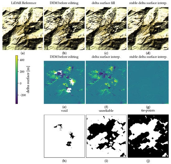
Figure 7.
Example of the stable delta surface interpolation. (a) LiDAR reference DEM, (b) TanDEM-X DEM before editing, (c) TanDEM-X DEM after delta surface interpolation, and (d) after stable delta surface interpolation. (e) delta surface with respect to the LiDAR for the unedited TanDEM-X DEM, (f) delta surface for the delta surface interpolation, (g) delta surface for the stable delta surface interpolation, (h) input TanDEM-X voids (black), (i) unreliable pixels (black), and (j) tie-points (black).
In order to have fully automatic processing, some issues need to be addressed. Operationally, we impose that the area, which has to include the tie-points, extends by 0.5 km2 from the gap borders, which corresponds to 500 pixels. There are some rare cases where not enough reliable tie-points are found within such an area. In these cases, we increase the margin for the bounding box to pixels. By doing so, the searching area is generally large enough, in order to have sufficient tie-points for smooth interpolation. In even fewer cases the gap could be in a tiny island, and an increase of the searching area for tie-points is meaningless. In these cases, a reference DEM is directly used to replace the missing TanDEM-X data.
Additionally, over snow- and ice-covered regions, as well as forested areas, one has to deal with a certain amount of penetration of the radar wave into the volume target on ground (i.e., the snow pack or the vegetation canopy). The latter depends on the radar sensor parameters, i.e., frequency, incidence angle, and perpendicular baseline, and on the target’s conditions, such as snow microstructure or forest density [30,31,32]. In this case, the mosaicked TanDEM-X global DEM represents the location of the radar mean phase center, averaged over multiple coverages, which were acquired at different times and with different geometries. The latter is typically located close to or under the surface layer. Regarding now the external reference DEMs used for editing it, the same considerations apply to other radar DEMs, such as SRTM. Optical DEMs represent the height of the surface, while LiDAR DEMs represent the height of the ground over vegetated areas and of the surface layer over snow- and ice-covered regions. Let us now consider the example of editing an extended void over a glacier. Here, the external reference is anchored to the TanDEM-X DEM through the stable delta surface interpolation. If the void does not extend outside the glacier borders, the external reference will be anchored to TanDEM-X DEM values retrieved over snow-covered areas. In this case, the interpolated height will therefore be consistent with the average height of the mean radar phase center, as retrieved from the original TanDEM-X DEM mosaic, and will therefore reside under the surface. On the contrary, if the void comprises an entire glacier, the external reference DEM will be anchored to nearby tie-points and the glacier surface will be completely substituted by the external reference, which, in case, e.g., of a LiDAR DEM will be an approximate of the surface height. In addition, in this case, the information on the kind of used external reference is of paramount importance when utilizing the edited TanDEM-X DEM for scientific applications.
2.3.3. Delta Reference Quality Check
After the application of the gap filling module, and in particular of the stable delta surface interpolation, we include in the processing chain a further automatic step to monitor the quality of the voids interpolation process. The most relevant information for performance analysis can be extracted from the delta space itself. Therefore, for each editing area, we group together pixels corresponding to four different regions before and after the gap-filling process. In particular, these regions are identified through the following masks:
- tie-points,
- unreliable pixels before editing,
- unreliable pixels after editing,
- filled voids.
For each masked region, we then compute and store the corresponding histogram and the root mean square error (RMSE) between the TanDEM-X DEM and the external reference DEM in the delta space.
As an example, Figure 8a shows the quality check results for all the unreliable pixels in the editing areas, i.e., located in the vicinity of each void, for the entire region of Australia. The horizontal and vertical axis of the scatter-plot show the RSME before and after editing, respectively. The green line represents the linear fitting of all samples, while the gray line shows the identity function. Clearly, almost all samples are below the latter, demonstrating how, after editing, the resulting DEM is in better agreement with the reference one. Figure 8b shows the histogram over every editing area in the geocell S39E175, situated in New Zealand. In this example, the height differences between the external reference DEM and the TanDEM-X DEM over tie-points (green) are concentrated around 0 m and 20 m, while for the unreliable pixels are widely distributed (orange). After the editing process, their spread is comparable with the tie-points (yellow). Moreover, the filled voids (red) show an even smaller dispersion around 0 m than the edited unreliable pixels.
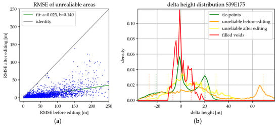
Figure 8.
(a) RMSE quality check example over Australia: for each edition area the RMSE is calculated before editing and after editing, (b) normalized histogram quality check example over geocell S39E175 in New Zealand.
2.4. Water Flattening
The complete flow-chart describing the water flattening approach is shown in Figure 9. The process starts with the classification of water bodies into ocean water, lakes, and rivers, as already explained in Section 2.2. For oceans, a rather simple referencing to the geoid heights is performed. For lakes, the predominant shoreline height is determined and considered as reference for the lake surface height. It is then overlaid by the geoid undulation, in order to accurately represent the water level. Differently, in case a river is considered, it is necessary to model each river pixel separately, in order to follow its slightly descending slope, from the source to the mouth. Therefore, only shoreline pixels close to the actual pixel are taken into account to determine its local height.
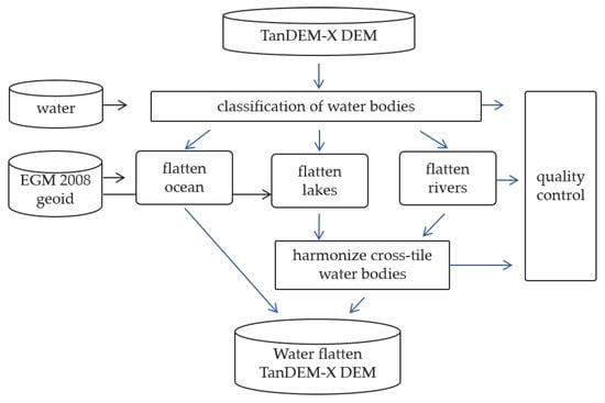
Figure 9.
Water body editing workflow.
Moreover, when considering lakes and rivers, it is finally important to harmonize the water bodies which cross DEM geocells borders, in order ensure a continuous surface along neighboring geocells. Flattening and harmonization are performed sequentially, in order to efficiently parallelize the algorithms. After each step, a specific quality control can be performed, in order to verify the successful generation of the edited geocells. In the following subsections, the above-mentioned procedures are detailed.
2.4.1. Ocean Flattening
Ocean flattening is performed by simply applying the geoid heights to the detected ocean water surfaces. The most important input for the ocean flattening is a map containing the geoid heights of the Earth with reference to WGS84. The TanDEM-X DEM is provided in WGS84 datum, which eases the application of the geoid undulations [33]. For this procedure, as reference geoid map, we utilize the realization of the Earth Gravitational Model 2008 is used with the EGM2008 data in a resolution of 1 min × 1 min [34,35], which corresponds to a pixel size of about 1.9 km at the equator. We then apply a bi-linear interpolation in order to match the output DEM resolution of 30 m, and finally substitute the input noisy/void ocean surface with the corresponding interpolated height. By correctly utilizing the EGM2008 geoid heights, ocean water areas at the border between neighboring geocells already appear at the same level. Hence, no additional step is needed to adjust the water level height at cross-geocell borders.
A quality control is then performed by extracting the shoreline pixels. If these pixels deviate by more than 10 meters from the ocean water level this could indicate an error in the application of the EGM2008 map and is marked in the quality control map. On the other hand, also phase unwrapping errors especially at mountainous coast lines can lead to high deviations. The algorithm runs automatically, and such information is stored for visual inspection and performance analysis purposes.
2.4.2. Lake Flattening
For flattening a lake water body, it is necessary to first determine the predominant shoreline height. Figure 10a shows an exemplary schematic distribution of height pixels around a lake. The pixels in green are shoreline pixels next to the water body (in blue) with a height close to the water surface height. Especially for lakes in mountainous areas, the presence of rocks, cliffs, or very steep terrain slopes may lead to heights in neighboring pixels which differ by several tens of meters with respect to the water surface. These are identified by the orange and brown pixels. In addition, due to shadow or layover effects, there may be pixels carrying a very noisy height information, i.e., showing a high variability among neighboring ones (in gray). In this case, the height of pixels can change by several tens of meters or even lay below the water surface. Taking the height of these pixels as the lake surface height, would prevent water from running out of the lake when applying hydro-logical models. However, it would also result in the presence of artifacts at the shoreline, which are not present in the real environment.
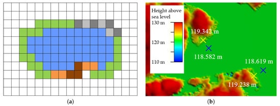
Figure 10.
(a) Shoreline determination for estimating the predominant shoreline height. Blue are lake pixels, green represents the shoreline close to the lake height, orange and brown pixels mountains or cliffs and gray noisy height. (b) Example showing the performance of the lake flattening procedure over Lake Gairdner, Australia. Blue crosses indicate the height of the water body and the yellow crosses the height of dry, unedited land areas, close to the water.
After an empirical analysis considering different lakes, we observed that pixels close to the water level (green pixels in Figure 10a) are generally the ones which best approximate the predominant shoreline, and are thus the lowest value of it is considered as the reference height for flattening the lake surface. A histogram of the occurrences of all shoreline height values is determined as shown in Figure 11. From the histogram, the reference height is the height where the occurrence value in the histogram drops to one fourth of the peak occurrence (towards lower height values). This reference height plus the the geoid undulation is finally applied to precisely flatten each individual lake pixel. A quality control parameters is again computed and stored for performance analysis purposes, by exploiting the statistics of the shoreline pixels. In this case, the standard deviation of the shoreline pixels is considered. If this value exceeds the limit of 10 m, a warning is raised and the lake is marked in the corresponding quality control map.
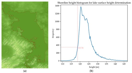
Figure 11.
Lake Gairdner, Australia. (a) DEM and shoreline in red. (b) Histogram of the height of the shoreline pixels.
An example for the verification of the lake flattening procedure is given in Figure 10b. It shows the water-flattened DEM of Lake Gairdner in Australia. This lake is only partly flooded and offers the possibility to compare the water height with dry lake areas nearby. The crosses in the image show measurement points, the blue ones are positioned within the lake, while the yellow ones are close to the shoreline on land. The dry land areas are less than one meter higher than the lake height, confirming the high precision of the described approach.
2.4.3. River Flattening
River flattening is the most computing intensive flattening step. Rivers are generally characterized by a certain downslope gradient, which is rather low for wide rivers, but potentially steeper for medium-sized rivers in mountainous areas. Therefore, rivers need to be locally flattened for each pixel, separately. This principle is shown in Figure 12a, where the pixel in dark blue represents the one to be flattened. In order to do so, the two nearest opposite shorelines are first determined (red-framed pixels). These shoreline pixels generally represent the shores perpendicular to the flow direction of the river. Hence, they are characterized by a slightly higher elevation with respect to the individual river pixel height. Several pixels around these two initial ones contouring the river bed as well as the ones in the second row are considered in order to increase the robustness of the estimation, as shown by the yellow striped boxes in Figure 12a. Indeed, this two-row-pixel shoreline helps reducing the influence of embankments along the river, which often bias the height estimation and would lead to overestimated river heights. Then the 30th percentile from the distribution of this set of pixels is calculated and is utilized as reference stable shoreline height. Finally, from this stable shoreline height value we subtract 1.5 m and use the result as reference value for flattening the considered river pixel.
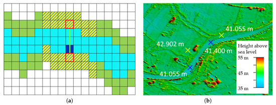
Figure 12.
(a) Basic principle for the determination of the river bed height. Light blue is the river mask, dark blue pixel which height is being estimated, yellow striped are the pixels in which heights are considered. (b) Exemplary result of the river editing procedure by the river Elbe, Germany. The blue crosses indicate the water heights, while the yellow ones indicate the heights over land.
Figure 12b shows the river Elbe in Germany as an example for river flattening. The height of the river surface indicated by the blue crosses coincides very well with the surrounding land heights, indicated by the yellow crosses, and are representative for the good performance of the river editing procedure. A final quality control for river editing is done by calculating the variation of neighboring river pixels. If the standard deviation is larger than 20 m, the pixels are indicated in the quality control plots and can be further analyzed.
2.4.4. Cross-Geocell Harmonization
Finally, a cross-geocell harmonization is performed. Water bodies spreading over two or more DEM tiles need to be harmonized to ensure a common height at geocell borders, i.e., to avoid jumps in a lake or a river. For lakes, the same procedure described in Section 2.4.2 is applied for the concerned geocells in order to find the common predominant shoreline height. For rivers, only the pixels close to the tile border are considered. Here, the same procedure as for river flattening is applied, i.e., by considering the shoreline pixels from neighboring geocells closest to the considered water pixel.
This harmonization procedure is performed after the flattening of all tiles of the considered region is completed. In that way, the flattening can be performed in parallel in a random sequence over all different identified water bodies. Afterwards, also the harmonization can be performed in parallel but block-wise, for blocks covering for example ten geocells in latitude and longitude directions.
The harmonization quality control involves a check to see if the lakes and rivers to be harmonized show differences in the height levels of more than 10 m, e.g., due to a small pieces with low shoreline statistics in one geocell. If this is the case, the lakes are marked in the quality control map. It is also checked if all large lakes and rivers on the border have a counterpart in the neighboring geocell, as it is very unlikely that a lake or river ends at a tile border.
Finally, at the end of all the water flattening procedure for a single geocell, a quality control summary table is saved. Here, all relevant findings for the water flattening of each DEM tile are summarized and can be checked for performance analysis purposes.
2.5. Editing Mask
The editing mask is a 16-bits geocoded layer that is generated for each edited TanDEM-X DEM geocell. Each pixel contains information on the application of an editing procedure, as well as on the specific algorithm, which is coded in different bits. A summary of the bits coding and meaning is shown in Table 1. The first two bits (0 and 1) are used to identify edited pixels and categorize them into either land or water. In case of water, four bits (from 2 to 5) are then assigned for the identification of the water body coupled to a flattening approach, while, in case of land, six bits (from 6 to 11) are associated to the different methods for filling gaps and report on the used external reference DEMs as well. Finally, one last bit identifies pixels at the border of a geocell which have been homogenized with their counterparts in the overlapping neighbor geocell.
3. Results and Performance
The full automatic algorithm has been applied and locally tested on different geocells, randomly selected around the globe. After rigorous testing, the operational global editing has already started. Up to date, completely processed are Europe, Australia, and New Zealand. A series of editing examples at local as well as operational large scale are presented in Section 3.1. Whereas, in Section 3.2, quality check parameters for the gap filling areas at continental scale are assessed and the computing performance is summarized.
3.1. Results
Figure 13 exhibits a selection of 3 sites in Europe: from top-to-bottom, (i) the Swiss Alps around lake Maggiore, (ii) the German/Austrian Alps around Königssee, and (iii) Karpathos island, Greece. From left-to-right, each column shows (a) the unedited TanDEM-X DEMs, (b) the corresponding edited TanDEM-X DEMs, and (c) a simplified version of the editing mask. The legend of the editing mask can be found at the bottom of the figure. The first considered region (i), close to lake Maggiore, presents a big solid gap, while the second one (ii), located around Königsee, shows large areas of unreliable heights in the unedited DEM version. Overall, the big solid gap in (i) covers an area of about 427 km2 (orange) with an unreliable surrounding area of about 157 km2 (light orange).
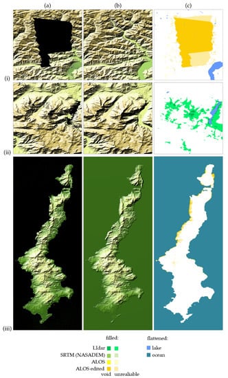
Figure 13.
Example of 3 local edited areas: (i) the Swiss Alps around lake Maggiore, (ii) the German/Austrian Alps around Königssee, (iii) Karpathos island, Greece. From left-to-right, each column shows: (a) the unedited TanDEM-X DEMs, (b) the corresponding edited TanDEM-X DEMs, (c) the editing mask.
High-relief terrain regions, such as the Alps, are often affected by significant geometric distortions, given the side-looking nature of SAR. Thus, the derived topographic heights are often noisy or even completely corrupted. This is a frequent situation in TanDEM-X in presence, e.g., of a single or very few acquisitions used in the final mosaicking process. In particular, considering now the first region (i), this effect is visible in the vicinity of the big solid gap, resulting in a high density of small/medium-size voids. Note that the big solid gap is caused by the lack of acquisitions with sufficient quality to be used for mosaicking. All these gaps are then filled using different external reference DEMs, as described by the figure’s legend. Moreover, the water surface of the lake Maggiore is properly flattened as well. From a visual inspection, the corresponding edited DEM (column (b)) shows no significant residual artifacts. Finally, the RMSE for the unreliable heights surrounding big solid gap is reduced from 52.9 m to 11.8 m in the edited version, whereas the tie-points present a RMSE of 17.3 m, and the filled voids of 10.3 m.
In the second example (ii), located by the Königsee, Germany, we can observe that the unreliable areas surrounding the single gaps are much larger than the gaps themselves. Indeed, the gap areas extend by 3.2 km2, while the derived surrounding unreliable areas are over 10 times bigger, achieving 33.6 km2. The RMSE of the main unreliable area before editing was 194.8 m, which, after editing, is improved to 17.8 m, similar to the tie-points RMSE of 17.1 m. The editing result of this particular site firmly confirms the goodness of the automatized procedure to select the reliable tie-points.
The third example (iii) depicts the island of Karpathos, Greece. It is characterized by the presence of large disperse gaps, mainly concentrated along the coasts, and by the need for flattening the surrounding water surface of the Mediterranean Sea. Here, the unreliable area (14.4 km2) is twice as big as the gap (7.8 km2). We can appreciate that, after editing, the water edges appear very smooth and the shoreline is consistent with the southeastern part of the island. The unreliable pixels, concentrated on the right-hand side of the island, presented an RMSE before editing of about 51 m, which is reduced after editing to only 8.3 m.
The edited regions of New Zealand, Australia, and Europe present different amounts of editing areas. Table 2 resumes the identification of the areas that have been edited. We can notice that the total filled unreliable areas surrounding a gap present an overall extension larger than the gaps themselves, where the total gaps area represents 35% of the filled pixels. Regarding the amount of rivers, whose height estimation and flattening is very time consuming, they are less than 0.35% of the total inland water bodies. To date, a total of over 2 million fragments, covering an area of 332.330 km2, have been edited.

Table 2.
Editing summary operational.
3.2. Large-Scale Performance
The performance of the operationally edited large-scale zones can be assessed in the delta surface space. The delta surface histograms ‘tie-points’, ‘unreliable pixels after editing’, and ‘filled voids’ are aggregated together, in order to obtain a single distribution for the edited area, i.e., at a local scale. Subsequently, these distributions can be also aggregated for each geocell and, furthermore, all geocells in each continent to retrieve a quality parameter at national/continental scale. Figure 14a presents the normalized aggregated histograms for the operationally edited zones of Europe, Australia, and New Zealand. Moreover, for each zone, the corresponding 5th and 95th percentiles are highlighted on the horizontal axis with dashed, colored lines. We can observe that Australia, which also presents the smallest void area in the unedited version and, proportionally, the largest unreliable area, shows the smallest aggregated delta surface for edited areas within the central 90% range, varying from −8.7 m up to 6 m. Regarding New Zealand and Europe, the same range varies from −19.9 m to 16.2 m and from −18.2 m to 18.4 m, respectively. Moreover, in Figure 14b,c, we consider the edited geocells over Europe and display the histogram and a two-dimensional map of the RMSE value per geocell, respectively. One can note that most geocells have an RMSE value between 0 m and 17 m. The regions that exceed this RMSE value are mainly located in the Alps and Norway, regions characterized by the presence of high-relief terrain.
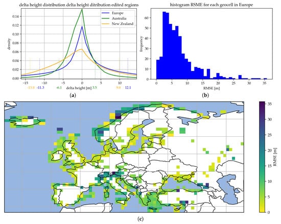
Figure 14.
(a) Delta height density for all the edited regions vertical dotted lines show the 5th and 95th percentiles. (b) Histogram delta height RMSE for all edited regions in Europe grouped by geocell. (c) Distribution delta height RMSE for all edited regions in Europe.
Finally, in order to comment on the overall computational performance, we can consider New Zealand as exemplary case, which comprises 66 geocells to be edited. Two different processing servers were used for editing: for gap filling and identification of editing areas we utilized a Intel(R) Xeon(R) CPU E5-2698 v4 (20 cores), 512 GB RAM (local SSD storage), while for water flattening a Intel(R) Xeon(R) Gold 6130 CPU (16 cores), 756 GB RAM. The identification of editing areas took about 20 minutes, to identify different gaps and merge 24 pairs of geocells. A total of 1128.6 km, distributed over 1314 gaps needed to be filled. The gap filling procedure took around 1 hour when processing with 10 cores in parallel. The water flattening algorithm was completed within less than 3.5 h, by exploiting 10 cores in parallel, while the harmonization lasted less than one hour using one single core only. Overall, a total of 34 rivers, covering an area of 24.82 km2, and 17,190 lakes, covering an area of 3435.46 km2, were flattened. The total amount of ocean pixel surrounding the land in the considered geocells is about 478 millions.
4. Conclusions
In this paper, we presented the algorithms developed at the German Aerospace Center (DLR) Microwaves and Radar Institute for a fast, fully automatic editing of the global TanDEM-X DEM, which comprises gap filling and water flattening. First of all, gaps and noisy water bodies are identified and properly classified on a geocell basis. Individual filling techniques are then applied depending on the type of gap. In particular, if an external reference DEM is available, we utilize the stable delta interpolation procedure, otherwise a linear or inverse distance weighted interpolation of neighboring pixels is applied. Moreover, a new water-body layer (WBL) has been derived and used as input for discarding voids and as a masking reference for the implemented water flattening approach. Water flattening consists of three different flattening procedures for ocean, lakes, and rivers, respectively. A harmonization takes care of flat lakes and rivers even along the borders of neighboring geocells. Finally, the main editing information is saved into the editing mask, which is associated to the output product. The algorithms are managed by a higher-level framework and run completely automatized without need for any external operator. The performance analysis and quality check demonstrate the good quality and consistency achieved by the delivered product.
The newly edited TanDEM-X DEM version is generated at 30 m resolution to limit the computational load. Nevertheless, all algorithms can also be applied at the nominal full resolution of 12 m without any particular issue. The operational global processing of this newly edited TanDEM-X DEM version is currently on-going and is foreseen to be completed at the beginning of 2021. The partial product has already started to be used as reference DEM for the processing of the upcoming TanDEM-X Change DEM layer [36,37].
Author Contributions
Conceptualization, C.G., M.B., J.-L.B.-B., and P.R.; methodology, C.G., M.B., J.-L.B.-B., and P.R.; software, C.G., M.B., and J.-L.B.-B.; validation, C.G., M.B., and J.-L.B.-B.; investigation, C.G., M.B., and J.-L.B.-B.; data curation, C.G., M.B., and J.-L.B.-B.; writing—original draft preparation, C.G., M.B., and P.R.; writing—review and editing, C.G., M.B., J.-L.B.-B., P.R., and M.Z.; supervision, P.R. and M.Z. All authors have read and agreed to the published version of the manuscript.
Funding
This research received no external funding.
Conflicts of Interest
The authors declare no conflict of interest.
References
- Hawker, L.; Rougier, J.; Neal, J.; Bates, P.; Archer, L.; Yamazaki, D. Implications of Simulating Global Digital Elevation Models for Flood Inundation Studies. Water Resour. Res. 2018. [Google Scholar] [CrossRef]
- Archer, L.; Neal, J.; Bates, P.; House, J. Comparing TanDEM-X Data with Frequently-Used DEMs for Flood Inundation Modelling. Water Resour. Res. 2018. [Google Scholar] [CrossRef]
- Farr, T.G.; Rosen, P.A.; Caro, E.; Crippen, R.; Duren, R.; Hensley, S.; Kobrick, M.; Paller, M.; Rodriguez, E.; Roth, L.; et al. The Shuttle Radar Topography Mission. Rev. Geophys. 2007, 45. [Google Scholar] [CrossRef]
- Yamaguchi, Y.; Kahle, A.B.; Tsu, H.; Kawakami, T.; Pniel, M. Overview of Advanced Spaceborne Thermal Emission and Reflection Radiometer (ASTER). IEEE Trans. Geosci. Remote Sens. 1998, 36, 1062–1071. [Google Scholar] [CrossRef]
- Abrams, M.; Crippen, R.; Fujisada, H. ASTER Global Digital Elevation Model (GDEM) and ASTER Global Water Body Dataset (ASTWBD). Remote Sens. 2020, 12, 1156. [Google Scholar] [CrossRef]
- Takaku, J.; Tadono, T. PRISM On-Orbit Geometric Calibration and DSM Performance. IEEE Trans. Geosci. Remote Sens. 2009, 47, 4060–4073. [Google Scholar] [CrossRef]
- Crippen, R.; Buckley, S.; Agram, P.; Belz, E.; Gurrola, E.; Hensley, S.; Kobrick, M.; Lavalle, M.; Martin, J.; Neumann, M.; et al. Nasadem global elevation model: Methods and progress. Int. Arch. Photogramm. Remote Sens. Spat. Inf. Sci. 2016, XLI-B4, 125–128. [Google Scholar] [CrossRef]
- Simard, M.; Neumann, M.; Buckley, S. Validation of the new SRTM digital elevation model (NASADEM) with ICESAT/GLAS over the United States. In Proceedings of the 2016 IEEE International Geoscience and Remote Sensing Symposium (IGARSS), Beijing, China, 10–15 July 2016; pp. 3227–3229. [Google Scholar] [CrossRef]
- Krieger, G.; Moreira, A.; Fiedler, H.; Hajnsek, I.; Werner, M.; Younis, M.; Zink, M. TanDEM-X: A satellite formation for high-resolution SAR interferometry. IEEE Trans. Geosci. Remote Sens. 2007, 45, 3317–3341. [Google Scholar] [CrossRef]
- Rizzoli, P.; Martone, M.; Gonzalez, C.; Wecklich, C.; Bräutigam, B.; Borla Tridon, D.; Bachmann, M.; Schulze, D.; Fritz, T.; Huber, M.; et al. Generation and Performance Assessment of the Global TanDEM-X Digital Elevation Model. ISPRS J. Photogramm. Remote Sens. 2017, 132, 119–139. [Google Scholar] [CrossRef]
- Gonzalez, C.; Rizzoli, P. Landcover-dependent assessment of the relative height accuracy in TanDEM-X DEM products. IEEE Geosci. Remote Sens. Lett. 2018, 15, 1892–1896. [Google Scholar] [CrossRef]
- WorldDEMTM. 2019. Available online: https://worlddem-database.terrasar.com/ (accessed on 2 December 2020).
- Earth Observation Center. The TanDEM-X PolarDEM Project. 2020. Available online: https://www.dlr.de/eoc/en/desktopdefault.aspx/tabid-11882/20871_read-66374 (accessed on 2 December 2020).
- Wendleder, A.; Breunig, M.; Martin, K.; Wessel, B.; Roth, A. Water body detection from TanDEM-X data: Concept and first evaluation of an accurate water indication mask. In Proceedings of the IEEE Symposium on Geoscience and Remote Sensing (IGARSS), Vancouver, BC, Canada, 4–29 July 2011. [Google Scholar]
- Valdo, P.; Sica, F.; Rizzoli, P. Improvement of TanDEM-X Water Mask by Exploiting the Acquisition Geometry. In Proceedings of the EUSAR 2018—12th European Conference on Synthetic Aperture Radar, Aachen, Germany, 4–7 June 2018. [Google Scholar]
- Jähne, B.; Scharr, H.; Körkel, S.; Jähne, B.; Haußecker, H.; Geißler, P. Principles of Filter Design. In Handbook of Computer Vision and Applications; Academic Press: Cambridge, MA, USA, 1999; Volume 2, pp. 125–151. [Google Scholar]
- Beucher, S.; Lantuejoul, C. Use of Watersheds in Contour Detection. In Proceedings of the International Workshop on Image Processing: Real-time Edge and Motion Detection/Estimation, Rennes, France, 17–21 September 1979. [Google Scholar]
- Wendleder, A.; Wessel, B.; Roth, A.; Breunig, M.; Martin, K.; Wagenbrenner, S. TanDEM-X Water Indication Mask: Generation and First Evaluation Results. IEEE J. Sel. Top. Appl. Earth Obs. Remote Sens. 2012, 6, 1–9. [Google Scholar] [CrossRef]
- Grohman, G.; Kroenung, G.; Strebeck, J. Filling SRTM Voids: The Delta Surface Fill Method. Photogramm. Eng. Remote Sens. 2006, 72, 213–216. [Google Scholar]
- Bamler, R.; Hartl, P. Synthetic aperture radar interferometry. Inverse Probl. 1998, 14, R1–R54. [Google Scholar] [CrossRef]
- Chen, X.; Sun, Q.; Hu, J. Generation of Complete SAR Geometric Distortion Maps Based on DEM and Neighbor Gradient Algorithm. Appl. Sci. 2018, 8, 2206. [Google Scholar] [CrossRef]
- Deilami, K.; Hashim, M. Very high resolution optical satellites for DEM generation: A review. Eur. J. Sci. Res. 2011, 49, 542–554. [Google Scholar]
- Wang, S.; Ren, Z.; Wu, C.; Lei, Q.; Gong, W.; Ou, Q.; Zhang, H.; Ren, G.; Li, C. DEM generation from Worldview-2 stereo imagery and vertical accuracy assessment for its application in active tectonics. Geomorphology 2019, 336, 107–118. [Google Scholar] [CrossRef]
- Digital LiDAR-Terrain Models of Austria. Available online: http://data.opendataportal.at/dataset/dtm-austria (accessed on 23 July 2019).
- Digital Elevation Model (DEM) of Australia Derived from LiDAR 5 Metre Grid. Available online: https://ecat.ga.gov.au/geonetwork/srv/eng/catalog.search#/metadata/89644 (accessed on 19 May 2020).
- NASA Jet Propulsion Laboratory. NASADEM: Creating a New NASA Digital Elevation Model and Associated Products. 2020. Available online: https://earthdata.nasa.gov/esds/competitive-programs/measures/nasadem (accessed on 18 February 2020).
- Japan Aerospace Exploration Agency (JAXA). ALOS Global Digital Surface Model “ALOS World 3D—30 m (AW3D30)”. Available online: https://www.eorc.jaxa.jp/ALOS/en/aw3d30/index.htm (accessed on 15 April 2019).
- Pennec, X.; Cachier, P.; Ayache, N. Understanding the “demon’s algorithm”: 3D non-rigid registration by gradient descent. In International Conference on Medical Image Computing and Computer-Assisted Intervention; Springer: Berlin/Heidelberg, Germany, 1999; pp. 597–605. [Google Scholar] [CrossRef]
- Lowekamp, B.C.; Chen, D.T.; Ibáñez, L.; Blezek, D. The design of SimpleITK. Front. Neuroinform. 2013, 7, 45. [Google Scholar] [CrossRef]
- Rizzoli, P.; Martone, M.; Rott, H.; Moreira, A. Characterization of Snow Facies on the Greenland Ice Sheet Observed by TanDEM-X Interferometric SAR Data. Remote Sens. 2017, 9, 315. [Google Scholar] [CrossRef]
- Martone, M.; Rizzoli, P.; Krieger, G. Volume decorrelation effects in TanDEM-X interferometric SAR data. IEEE Geosci. Remote Sens. Lett. 2016, 13, 1812–1816. [Google Scholar] [CrossRef]
- Martone, M.; Rizzoli, P.; Wecklich, C.; Gonzalez, C.; Bueso-Bello, J.L.; Valdo, P.; Schulze, D.; Zink, M.; Krieger, G.; Moreira, A. The Global Forest/Non-Forest Map from TanDEM-X Interferometric SAR Data. Remote Sens. Environ. 2018, 205, 352–373. [Google Scholar] [CrossRef]
- Wessel, B. TanDEM-X Ground Segment—DEM Products Specification Document; Technical Report TD-GS-PS-0021; German Aerospace Center (DLR): Wessling, Germany, 2019. [Google Scholar]
- Pavlis, N.K.; Holmes, S.A.; Kenyon, S.C.; Factor, J.K. The development and evaluation of the Earth Gravitational Model 2008 (EGM2008). J. Geophys. Res. Solid Earth (1978–2012) 2012, 117. [Google Scholar] [CrossRef]
- Earth Gravitational Model. 2008. Available online: http://earth-info.nga.mil/GandG/wgs84/gravitymod/egm2008/SmallEndian/Undmin1x1egm2008isw=82WGS84TideFreeSE.gz (accessed on 15 November 2020).
- Bachmann, M.; Tridon, D.B.; Martone, M.; Sica, F.; Buckreuss, S.; Zink, M. How to Update a Global DEM—Acquisition Concepts for TanDEM-X and Tandem-L. In Proceedings of the EUSAR 2018—12th European Conference on Synthetic Aperture Radar, Aachen, Germany, 4–7 June 2018. [Google Scholar]
- Lachaise, M.; Schweisshelm, B.; Fritz, T. The New Tandem-X Change Dem: Specifications And Interferometric Processing. In Proceedings of the 2020 IEEE Latin American GRSS ISPRS Remote Sensing Conference (LAGIRS), Santiago, Chile, 22–26 March 2020; pp. 646–651. [Google Scholar]
Publisher’s Note: MDPI stays neutral with regard to jurisdictional claims in published maps and institutional affiliations. |
© 2020 by the authors. Licensee MDPI, Basel, Switzerland. This article is an open access article distributed under the terms and conditions of the Creative Commons Attribution (CC BY) license (http://creativecommons.org/licenses/by/4.0/).