Article

Underwater 3D Rigid Object Tracking and 6-DOF Estimation: A Case Study of Giant Steel Pipe Scale Model Underwater Installation

1
Department of Geomatics, National Cheng Kung University, Tainan 701, Taiwan
2
Kuo Toong International Co., Ltd., Kaohsiung 81357, Taiwan
*
Author to whom correspondence should be addressed.
Remote Sens. 2020, 12(16), 2600; https://doi.org/10.3390/rs12162600
Submission received: 30 June 2020 / Revised: 23 July 2020 / Accepted: 10 August 2020 / Published: 12 August 2020
(This article belongs to the Special Issue Underwater 3D Recording & Modelling)

Abstract

:
The Zengwen desilting tunnel project installed an Elephant Trunk Steel Pipe (ETSP) at the bottom of the reservoir that is designed to connect the new bypass tunnel and reach downward to the sediment surface. Since ETSP is huge and its underwater installation is an unprecedented construction method, there are several uncertainties in its dynamic motion changes during installation. To assure construction safety, a 1:20 ETSP scale model was built to simulate the underwater installation procedure, and its six-degrees-of-freedom (6-DOF) motion parameters were monitored by offline underwater 3D rigid object tracking and photogrammetry. Three cameras were used to form a multicamera system, and several auxiliary devices—such as waterproof housing, tripods, and a waterproof LED—were adopted to protect the cameras and to obtain clear images in the underwater environment. However, since it is difficult for the divers to position the camera and ensure the camera field of view overlap, each camera can only observe the head, middle, and tail parts of ETSP, respectively, leading to a small overlap area among all images. Therefore, it is not possible to perform a traditional method via multiple images forward intersection, where the camera’s positions and orientations have to be calibrated and fixed in advance. Instead, by tracking the 3D coordinates of ETSP and obtaining the camera orientation information via space resection, we propose a multicamera coordinate transformation and adopted a single-camera relative orientation transformation to calculate the 6-DOF motion parameters. The offline procedure is to first acquire the 3D coordinates of ETSP by taking multiposition images with a precalibrated camera in the air and then use the 3D coordinates as control points to perform the space resection of the calibrated underwater cameras. Finally, we calculated the 6-DOF of ETSP by using the camera orientation information through both multi- and single-camera approaches. In this study, we show the results of camera calibration in the air and underwater environment, present the 6-DOF motion parameters of ETSP underwater installation and the reconstructed 4D animation, and compare the differences between the multi- and single-camera approaches.

Graphical Abstract

1. Introduction

The Zengwen reservoir is Taiwan’s largest and has a designed capacity of six billion m3. On average, its siltation rate has been four million m3 per year since it was built in 1973. However, the 2019 typhoon Morakot brought heavy rainfall with an accumulation of >3000 mm in five days [1], leading to numerous serious landslides in mountainous areas and bringing 90 million m3 silt into the Zengwen reservoir [2]. As depicted in Figure 1a, these huge deposits built up the reservoir sedimentation surface to elevation (EL.) 175.0 m, and covered the intake of the hydropower generator (at EL. 165.0 m) and the permanent river outlet (at EL. 155.0 m). To increase the desilting ability and extend the life of the Zengwen reservoir, the Taiwan government launched a new desilting project in 2014 and completed the construction of a new 1.2 km bypass tunnel in 2018. For details, see [3]. However, due to the water level being up to 60 m, it was not possible to construct the tunnel intake using the traditional cofferdam method. In addition, the tunnel excavation elevation could only feasibly reach EL 195.0 m, which is still 20 m higher than the sedimentation surface, thus limiting its desilting capability. To overcome the construction difficulty, the contractor proposed a novel solution of directly installing a huge Elephant Trunk Steel Pipe (ETSP) under the water to connect the tunnel and extending it downward to reach the reservoir sedimentation surface.

1.1. ETSP Underwater Installation

The ETSP is a double tube structured pipe with an inner diameter of 10 m, an outer diameter of 11.6 m, and a length of 54 m. Figure 1b,c shows the design diagram and on-site assembled ETSP. The head part is connected to the tunnel, while the tail with an antivortex steel cover is designed to reach the bottom and desilt the muddy water. According to its design, the body will float horizontally on the water surface when both nozzles are sealed with blind plates, making transport by water possible. During the underwater installation, water will be injected into the tube to adjust its attitude and make the ETSP sink to the bottom of the reservoir. As shown in Figure 1d, the ETSP underwater installation includes attitude adjustment and sinking stages.
To adjust the attitude of ETSP from floating horizontally (Figure 1d-1) to vertically (Figure 1d-2), a huge amount of water is injected into the inner tube to deduce its buoyancy. Since the tail is heavier than the head, the weight of the injected water will be unbalanced and concentrated at the tail, thus making the tail sink faster and finally rotate 90°. However, the ETSP still floats in the water as the outer tube provides buoyancy. For the purpose of sinking, several buoys with ropes are connected in series at the head and tail, and then water is injected into the outer tube to increase the density. To make the ETSP sink deeper, water is injected into the first set of buoys from the head (Figure 1d-3) to tail (Figure 1d-4) making the ETSP swing as it sinks. Then, water is continuously injected into the second set of buoys and so on until the ETSP has reached its installation location.
However, since the ETSP is huge and its underwater installation method is unprecedented, there are several uncertainties in its rotation direction, rotation rate, and displacement amount during attitude adjustment. To assure construction safety, a 1:20 ETSP scale model was used to simulate the transportation and underwater installation procedures [4], and its six-degree-of-freedom (6-DOF) motion parameters, consisting of three rotation angles and three translations, were monitored by offline underwater 3D rigid object tracking and photogrammetry. Since the size is strictly adjusted according to its original design, the actual movement can be estimated by Froude’s law of similitude [5]. In addition, a 4D animation can be reconstructed by integrating the 3D model and 6-DOF motion parameters, which can provide a comprehensive understanding of motion for on-site construction reference.

1.2. Related Work of 6-DOF Applications

Image-based 6-DOF parameters estimation mainly uses image matching or artificial marker detection, to reconstruct the relationship between scene/object and the camera, it has been widely used in navigation, robot vision, and industrial measurement applications. In navigation, the camera trajectory at different time epochs can be estimated through visual odometry [6,7]. For robot vision, the simultaneous localization and mapping (SLAM) technique can help the robot understand the relationship between environment and space both in real-time and automatically [8]. In industrial measurement applications, we can conduct 3D object tracking to monitor the motion phenomena of a rigid object [9].
Depending on the adopted number of cameras, 3D object tracking can be divided into the multi-camera approach [10] and the single-camera approach [11]. The multicamera approach adopts synchronized cameras to take images simultaneously where the images must have a certain overlap, and the camera rig information—such as the each camera’s internal orientation parameters (IOPs) and the relative orientation parameters (ROPs) among cameras—have to be well-calibrated and fixed [12]. Therefore, we can adopt multiple images’ forward intersection to calculate the rigid object’s surface coordinates, and then estimate an object’s 6-DOF motion parameters by tracking conjugate points between different epochs and performing 3D similarity coordinate transformation. One advantage of a calibrated multicamera system is direct 3D coordinate computation that can be further applied to rigid- and deformable-object motion analyses, such as 3D surface model reconstruction [13] or human body dynamic information extraction [14]. Unlike the multicamera system, the single-camera approach is limited to the analysis of rigid objects. It starts tracking the features on the surface of a rigid object and then sequentially reconstructs the camera orientations from structure-from-motion, or directly obtains them by the space resection of markers where the 3D coordinates are known as control points. Therefore, the single-camera approach can estimate the 6-DOF motion parameters by analyzing the camera orientations.
The differences between the multi- and single-camera approaches have been studied in detail and reported by [15]. They adopted a system of three synchronized video cameras [16] to monitor the velocity changes of the ship model while being hit by high-frequency waves. Since a multicamera system provides redundant measurement information, it achieves better accuracy. However, differences in the synchronization rate in a multicamera system will significantly affect the measurement reliability and it has both a higher cost and more complex system calibration than the single-camera approach.

1.3. Objectives and Challenges

ETSP attitude adjustment simulation is conducted in an underwater environment. Differences in refraction through different mediums can lead to changes in imaging geometry, such as increased focal length, image distortion, and significant chromatic aberration effects. Consequently, it is necessary to calibrate the IOPs of underwater cameras for accurate underwater photogrammetric applications [17,18]. In addition, the underwater environment means that specific extra equipment is needed to obtain reliable results, this includes housings to protect the cameras, tripods to fix them in position, and lighting sources to increase the brightness.
In this study, we used three cameras to monitor the 6-DOF motion parameters of the ETSP attitude adjustment simulation and compared the differences obtained from multi- and single-camera approaches in the underwater environment. However, due to the difficulty retrieving image feedback and that the wireless transmission is absorbed in the underwater environments, it is difficult to guide divers to position cameras and ensure their overlapping areas. We noticed that each camera could only observe the head, middle, or the tail parts of the ETSP, resulting in small overlap areas among all images for which we could not use conventional multiple-image forward intersection to perform 3D object tracking. Alternatively, we obtained the exterior orientation parameters (EOPs) of the multicamera system through space resection at each epoch, then proposed a multicamera coordinate transformation to calculate the 6-DOF parameters of ETSP. However, due to the significant attitude change of ETSP, each camera could only obtain 10–40% coverage at different sections of the ESTP’s body, so it is necessary to analyze its effects in 6-DOF parameters that were estimated through single-camera relative orientation transformation. Section 3.2 introduces the details of how these two methods are computed.
Section 2 describes the specifications of the ETSP scale model, adopted imaging equipment, experiment environment, and acquired sample images. Section 3 introduces the camera calibration in the air and underwater environment and details of how the 6-DOF parameters are computed. In Section 4, we discuss the differences in camera calibration results between in air and in water, introduce the 6-DOF motion parameters and reconstructed 4D animation of ETSP, and analyze the differences of multi- and single-camera approaches. Section 5 reports the findings and limitations of underwater object tracking.

2. ETSP Scale Model and Equipment

The ETSP scale model and coordinate system definition, the imaging equipment and auxiliary devices, the experiment environment, and the sample images of underwater attitude adjustment are introduced below.

2.1. ETSP Scale Model and Coordinate System Definition

The ETSP scale model is built based on the principle of geometrical similarity, meaning that the ratios of all dimensions for the model and prototype are equal and the density is consistent. According to Froude’s law of similitude [5], the size of the scale is the same as the scale factor λ (i.e., 20), while the scale factor of the weight and volume are λ 3 . Table 1 summarizes the details of the size of the prototype and scale model. We can see that about 67% of the ETSP will float on the water when the nozzles are sealed, and about 7% of the body can still be observed when the inner tube is full of water.
To conduct 3D object tracking, we utilized Australis© artificial coded markers [19] for autorecognition and computing 3D coordinates. In addition to the coded markers, circular bands with white dots were pasted on to the surface at equal intervals to help generate the 3D mesh model. By taking multiposition and multiangle images with a calibrated camera in the air (camera calibration will be discussed in Section 3.1), the artificial coded markers and white dots were detected automatically and their 3D coordinates were computed via bundle adjustment in Australis© software. Therefore, the 3D coordinates can be used as control points to estimate the EOPs of underwater cameras through space resection. The ETSP local coordinate system is defined on its horizontal floating status. Its origin point is the average coordinates of all surface points that can be regarded as the center of mass. The X-axis points to the head, the Y-axis is located on the horizontal plane, while the Z-axis depicts the height. Figure 2a shows the ETSP scale model and the distributions of the coded markers and circular bands with white dots while Figure 2b demonstrates the reconstructed 3D mesh model and its coordinate system definition.

2.2. Imaging Equipment and Auxiliary Devices

Figure 3 shows the imaging equipment adopted in this study, including a Sony A6000 camera that has 24 million pixels and 20 mm focal length, waterproof housing, a built-in time-lapse program, and an electrical synchronization trigger. Three cameras with waterproof housings are used and all cameras are synchronized through the trigger. The trigger is a simple device that can connect multiple cameras and send a synchronized electrical signal to take photos simultaneously. With the assistance of a built-in time-lapse program, once all cameras are connected and triggered simultaneously, all cameras will continually take images with the same time interval. Therefore, we can put each camera that is shooting in time-lapse mode into its waterproof housing and install it in the water. Meanwhile, to acquire clear images, we placed tripods in the water to fix the camera positions and included a 25,500 lumen waterproof LED to increase the brightness. Since a significant amount of the light is absorbed by the water, we set a camera imaging setting with a larger aperture (f/8), lower shutter speed (1/80 s), and higher ISO values (3200) to increase the marker detection capability.

2.3. Experiment Environment

The ETSP attitude adjustment simulation was conducted in a towing tank located in the basement of the Department of Systems and Naval Mechatronic Engineering at National Cheng Kung University. As shown in Figure 4a, the dimensions of the towing tank are: length 160 m, width 8 m, and depth 4 m. A carriage and a crane are mounted on the track of the towing tank, and the crane is used to lift the ETSP to the wall for the water injection experiment, while several bulbs are mounted on the carriage to increase the light in the indoor environment. In addition, an underwater camera calibration field is established at the wave absorbing slope. Figure 4b shows the towing tank and Figure 4c illustrates the experiment status and the relative positions between the ETSP, the three cameras labeled Cam1, Cam2, and Cam3, and the waterproof LED. Figure 4d depicts the water injection pumps with a total injection rate of 8 L/min. Since the volume of the inner tube is approximately 0.6 m3 (i.e., 600 L), the simulation process lasts about 75 min. Therefore, using a 1 s interval will exceed the maximum number of counters (i.e., 999) of the time-lapse program so we set the time interval to 25 s and each camera obtained 180 images.

2.4. Sample Images of ETSP Attitude Adjustment Simulation

Figure 5 depicts the sample images of the attitude adjustment; this depicts the initial, intermediate, and final status of the ETSP. We can see that since the tail of the ETSP sinks faster than the head, the imbalanced weight finally leads it to rotate 90°. Due to the difficulty of underwater installation, each camera only monitors the motion of the head, middle, or tail part of the body. Therefore, it is necessary to compare the differences in the 6-DOF motion parameters when only part of the rigid body can be observed and calculated from a single-camera approach. Meanwhile, the orange, green, and red dots in Cam2 show only six common artificial markers among the three cameras, which means that there are too few points and less reliable to conduct successful 3D object tracking through a traditional multiple images forward intersection method.

3. Methodology

Figure 6 shows the proposed offline 3D rigid object tracking workflow for monitoring the ETSP’s 6-DOF motion parameters. Taking into account the refraction effect for different media, camera calibration for the 3D model reconstruction and underwater object tracking is conducted in the air and underwater environments, respectively. As described in Section 2.1, the ETSP 3D model is first built and its 3D coordinates are used as control points to estimate the EOPs of the camera through space resection. Using the known camera orientation information, the ETSP 6-DOF motion parameters can be calculated through multicamera coordinate transformation and single-camera relative orientation transformation. In the end, by integrating the 3D model and 6-DOF parameters, a 4D animation is constructed to provide a comprehensive understanding of underwater installation.

3.1. Camera Calibration

Camera calibration is an important procedure to correct the lens distortion for accurate image measurement. In addition, Australis coded markers are used to conduct self-calibration bundle adjustment with additional parameters [20]. Equations (1) and (2) depict the self-calibration bundle adjustment equations, while Equations (3) and (4) show the camera’s additional parameters. ( X o ,   Y o ,   Z o ) is the camera position, m 11   are the nine elements of the camera rotation matrix, ( X ,   Y ,   Z ) is the coordinates of image measurement (x, y) in object space, and ( Δ x ,   Δ y ) is the amount of lens distortion correction. The IOPs include the focal length f, principal points ( x p ,   y p ), radial lens distortion parameters ( K 1 ,   K 2 ,   K 3 ), and decentering parameters ( P 1 ,   P 2 ), in which r is the distance to the center of image measurement (x, y). In this study, camera calibration for ETSP 3D model reconstruction and 3D object tracking is conducted in the air and underwater environments, respectively.
x x p = f m 11 ( X X o ) + m 12 ( Y Y o ) + m 13 ( Z Z o ) m 31 ( X X o ) + m 32 ( Y Y o ) + m 33 ( Z Z o ) + Δ x
y y p = f m 21 ( X X o ) + m 22 ( Y Y o ) + m 23 ( Z Z o ) m 31 ( X X o ) + m 32 ( Y Y o ) + m 33 ( Z Z o ) + Δ y
Δ x = ( x x p ) ( K 1 r 2 + K 2 r 4 + k 3 r 6 ) + P 1 ( r 2 + ( x x p ) 2 ) + 2 P 2 ( x x p ) ( y y p )
Δ y = ( y y p ) ( K 1 r 2 + K 2 r 4 + k 3 r 6 ) + P 2 ( r 2 + ( y y p ) 2 ) + 2 P 1 ( x x p ) ( y y p )
As shown in Figure 7a, we used a 2 m radius rotatable circular disk for camera calibration in the air (Rau and Yeh, 2012) in which several coded markers were fixed at different heights on the disk. By rotating the disk to different angles and taking images at a fixed point with a 45° viewing angle, we can easily acquire images and obtain a good geometry of an intersection angle of 90°. Besides, since the different heights of the coded markers can establish a height field rather than a plane surface, we can acquire better accuracy for the calibrated focal length. However, Figure 7b shows that the underwater camera calibration was carried out at the wave absorbing slope. We can see that several steel frames have been placed to eliminate the wave energy where we attached the markers to the metal frame with magnets to construct the underwater calibration field. The calibration images were taken by a diver swimming with double-block flight lines to acquire both the vertical and oblique images with a high overlap ratio and larger convergent angles. In this study, all cameras are focused at 3 m, and only Cam1 is used for 3D coordinate estimation and underwater 3D rigid object tracking. Therefore, Section 4 also discusses the calibration differences between the different environments.

3.2. Motion Parameters Computation of 6-DOF

The computation of multicamera coordinate transformation and single-camera relative orientation transformation for 6-DOF motion parameters are described in detail the following sections.

3.2.1. Multicamera Coordinate Transformation

As shown in Figure 8a, the conventional multicamera approach fixes the camera position and orientation and estimates the coordinates (XYZ) of markers (M) from a multiple-image forward intersection. With Equation (5), the translation T i and rotation matrix R i of the 6-DOF motion parameters between epoch O and i can be calculated using the 3D coordinate transformation of markers from ( X Y Z o M ) to ( X Y Z i M ). Here, X Y Z i represents a group of 3D coordinates ( X i ,   Y i ,   Z i ) of markers at epoch i, T consists of the three elements of translation ( T X ,   T Y ,   T Z ), and R is composed of three rotation angles ( O ,   P ,   K ) . At least two cameras are needed to calculate the coordinates of markers and at least two conjugate makers are required between different epochs to solve the equation; more are needed for the least-squares adjustment computation. However, since there are only a few overlapping areas between images and only a few markers are used for object tracking, we cannot use the forward intersection approach to successfully estimate the 6-DOF motion parameters.
X Y Z i M = T i + R i × X Y Z o M
Alternatively, assuming that the ETSP is stationary, we can obtain the EOPs of the camera through space resection and the motion of the ETSP from the epoch O to epoch i can be regarded as the inverse of the motion in the multicamera system from epoch i to epoch O. As shown in Figure 8b and Equation (6), the translation T i and rotation matrix R i can be computed from 3D coordinate transformation of ( X Y Z i C ) to ( X Y Z o C ), in which the coordinates from markers (M) are replaced by the coordinates of the multicamera system (C). Please note the difference in the epochs between the two methods in Equations (5) and (6). Since it is not necessary to ensure the overlap area between cameras, it is more convenient and has fewer limitations to install the camera.
In this study, the 6-DOF motion parameters from multicamera approach are computed through the least-squares adjustment, and the root mean square errors (RMSE: σ) of coordinate transformation are estimated as an internal accuracy index.

3.2.2. Single-camera Relative Orientation Transformation

The single-camera approach considers the relationship of relative motion between a rigid object and a camera. Therefore, the 6-DOF motion parameters of a rigid object can be calculated from the relative orientation transformation of the camera’s EOPs. As shown in Equation (7), the rotation matrix R i of the object is equal to the relative rotation of the camera, in which R M C a m o and R C a m i M is the rotation matrix and transpose rotation matrix of camera at epochs O and i, respectively, and M represents the coordinate system defined on the object. To calculate the relative translation, as shown in Equation (8), T i is calculated using position P C a m i M at epoch i multiplied by the rotation matrix R i and then minus the camera position P C o M at epoch O.
R i = R M C a m o × R C a m i M
T i = P C a m i M × R i P C o M
In this study, we acquired one set of 6-DOF motion parameters from multicamera coordinate transformation and obtained three sets of results from the single-camera relative orientation transformation that monitors different parts of the ETSP’s body. The differences and analyses are discussed below.

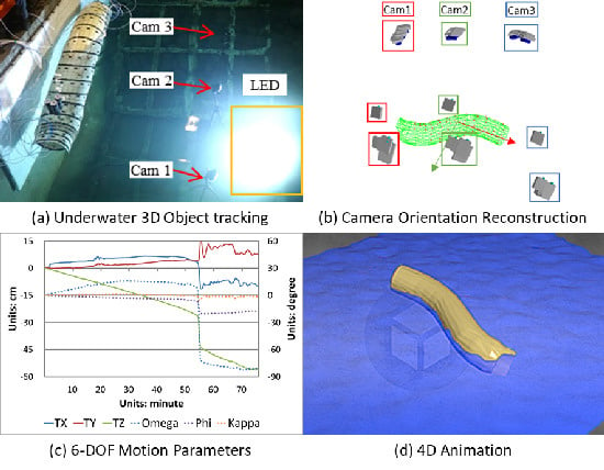
4. Results and Analysis

Here, we summarize the results of camera calibration in the different materials, present the 6-DOF motion parameters of the ETSP attitude adjustment and the reconstructed 4D animation, and compare the differences between the multi- and single-camera approaches.

4.1. Results of Camera Calibration

Cam1 is calibrated and compared in three different mediums, in air (Air), in air with waterproof housing (Housing), and underwater (UW); Table 2 summarizes the statistics for these three cases. Figure 9a,b shows the distributions of the acquired images and markers in the air and underwater camera calibration fields, respectively, and Figure 9c illustrates the lens distortion curve among three cases. Since the housing interface is very thin, we observed that the refraction of the glass only caused slight differences between the Air and Housing cases. However, there were significant differences observed in the UW case, where the radial distortion curve is inverted. This transforms the original barrel distortion effect into a notable pincushion distortion effect. Meanwhile, there is a focal length of 1.333-times difference between the Housing and UW cases, which is close to the refractive index of water (1.333) and leads to a change in the imaging geometry. In the accuracy assessment, we noted a decrease in the image measurement accuracy (sigma0) in underwater environments. This is because the diver is moving to take images with a slow shutter speed (1/60 s), and the motion blur effects influence the marker detection accuracy.

4.2. Motion Parameters and 4D Animation of ETSP

Figure 10 shows the orientation distributions of each camera at each epoch that were calculated by the space resection. We can understand that the ETSP is stationary and its motion can be treated as the camera’s relative motion, where the 6-DOF motion parameters of the ETSP are computed from multi- and single-camera approaches shown in Figure 11. These two methods clearly have a similar trend but the results obtained from the multicamera approach have more noise. The next section compares and assesses the accuracy of these two methods.
As depicted in Figure 11 and Phase (ii) in Figure 10, we can observe that the ETSP rotated 90° along the X-axis at 55 min and descended 30 cm within 2.5 min. Before and after this moment (Phases (i) and (iii) in Figure 10), the ETSP showed a stable descent during the water injection procedure. Through temporal analysis, we can calculate the motion and rotation velocity of the ETSP model where the Z-axis has a maximum motion velocity of about 140 cm/min and the X-axis has a maximum rotation velocity of about 195°/min. However, motion phenomena are difficult to understand when reading the numeric values. In contrast, by integrating the 3D model with the 6-DOF motion parameters, we can reconstruct the 4D animation to provide a comprehensive understanding of attitude adjustment. Figure 12 shows thumbnails of the 4D simulation and the results can be found at https://skfb.ly/PA9R.

4.3. Comparison of Multi- and Single-Camera Approaches

Figure 13 depicts the differences in the 6-DOF motion parameters at each epoch between multi- and single-camera approaches, where the results of the single-camera approach are acquired from Cam1. Figure 13 also depicts the internal accuracy index (σ) of the multicamera coordinate transformation where it is enlarged 30-fold so that the trends are clearly observable. Meanwhile, Table 3 summarizes the RMSEs between these two approaches and between each single-camera approach.
From Figure 13, we noticed that the largest error is located at the moment of ETSP rotation, which has a σ value of 2 mm, translations (ΔTX, ΔTY, ΔTZ) of (−1.1, −6.6, 8.6) cm, and rotation angles (ΔO, ΔP, ΔK) of (2.3, 0.1, −0.4) degrees, respectively. These effects were there because there remains a certain signal delay in multicamera synchronization, and the shutter speed (1/80 s) was too slow to capture the moment in rapid motion. Even though the multicamera approach can provide redundant information, the slight errors of coordinate transformation lead to noise in the 6-DOF motion parameters (see Figure 11a). However, although each single-camera approach can only observe a partial body of the ETSP, the RMSEs of the translation and rotation angles among each single-camera approach were very small at 0.09–0.28 cm and 0.01–0.06°, respectively, meaning that the differences in position and viewing angle and the partial observation of the rigid object would not affect the results. However, when comparing the results among each single-camera approach, we can see that Cam2 has a slight signal delay. Although the RMSEs of the single-camera approach were only 0.10–0.28 cm in translation and 0.01–0.06° in rotation angles, error propagation leads to significant increments of RMSEs in the multicamera approach in ΔTY, ΔTZ, and ΔO.
In summary, although the multicamera coordinate transformation approach has the potential to reach sub-cm accuracy in coordinate transformation, it is still restricted by the synchronization rate among cameras, which induces large errors during rapid motions. However, the single-camera approach is proven to have the flexibility for monitoring the motion of rigid objects and can be placed in any position to acquire reliable results at low cost and low computation complexity.

5. Conclusions and Discussion

This study introduces the Zengwen reservoir desilting project that aims to install a huge ETSP in the underwater environment. During its installation, a large amount of water is injected into the ETSP tube so that it floats horizontally and vertically. To assure construction safety, a scale model of the ETSP was built to simulate the underwater installation procedure and 6-DOF motion parameters were calculated using underwater object tracking through both multi- and single-camera approaches. Due to the difficulty of underwater camera installation, each camera only observed a partial body of the ETSP and conventional object tracking via the multiple-image forward intersection method was not possible. Based on the EOPs obtained from the space resection of the ETSP 3D model, we proposed an alternate multicamera coordinate transformation approach and adopted a single-camera relative orientation transformation method to calculate the 6-DOF motion parameters.
The differences analysis for the 6-DOF motion parameters shows high consistency between these two methods. The alternate multicamera approach is able to reach sub-cm accuracy and has less preparation work that needs no system calibration; however, it is still restricted by the synchronization rate where larger errors are observed when rapid motion occurs. Although only a partial body of the ETSP can be observed, comparisons with the single-camera approach prove that the results are not affected by the viewing angle, position, or coverage. This means that the installation of a single-camera is more flexible for monitoring the motion of rigid objects and has the advantages of low cost and computation complexity.

Author Contributions

J.-P.J.: Conceptualization, methodology, and writing—original draft preparation; J.-Y.R.: supervision and funding acquisition. C.-M.C.: resources and validation. All authors have read and agreed to the published version of the manuscript.

Funding

This research received no external funding.

Acknowledgments

The authors are grateful to Sheng-Chih Shen who provides the waterproof LED for underwater photogrammetry monitoring and Kircheis Liu of Novargo Technology Ltd. for providing assistance with the diving and underwater cameras installation.

Conflicts of Interest

The authors declare no conflict of interest.

References

  1. Yu, Y.C.; Jou, B.J.D.; Hsu, H.H.; Cheng, C.T.; Chen, Y.M.; Lee, T.J. Typhoon Morakot meteorological analyses. J. Chin. Inst. Eng. 2013, 37, 595–610. [Google Scholar] [CrossRef]
  2. Li, H.C.; Hsieh, L.S.; Chen, L.C.; Lin, L.Y.; Li, W.S. Disaster investigation and analysis of Typhoon Morakot. J. Chin. Inst. Eng. 2013, 37, 558–569. [Google Scholar] [CrossRef]
  3. Chang, S.H.; Chen, C.S.; Wang, T.T. Sediment Sluice Tunnel of Zengwen Reservoir and construction of section with huge underground excavation adjacent to neighboring slope. Eng. Geol. 2019, 260, 105227. [Google Scholar] [CrossRef]
  4. Jhan, J.P.; Rau, J.Y.; Chou, C. 4D animation reconstruction from multi-camera coordinates transformation ISPRS—International archives of the photogrammetry. Remote Sens. Spat. Inf. Sci. 2016, 41, 841–847. [Google Scholar]
  5. Heller, V. Scale effects in physical hydraulic engineering models. J. Hydraul. Res. 2011, 49, 293–306. [Google Scholar] [CrossRef]
  6. Nistér, D.; Naroditsky, O.; Bergen, J. Visual odometry. In Proceedings of the 2004 IEEE Computer Society Conference on Computer Vision and Pattern Recognition, Washington, DC, USA, 27 June–2 July 2004; Volume 651, pp. 652–659. [Google Scholar]
  7. Scaramuzza, D.; Fraundorfer, F. Visual odometry [tutorial]. IEEE Robot. Autom. Mag. 2011, 18, 80–92. [Google Scholar] [CrossRef]
  8. Davison, A.J.; Reid, I.; Molton, N.D.; Stasse, O. MonoSLAM: Real-Time Single Camera SLAM. IEEE Trans. Pattern Anal. Mach. Intell. 2007, 29, 1052–1067. [Google Scholar] [CrossRef] [PubMed] [Green Version]
  9. Luhmann, T. Close range photogrammetry for industrial applications. ISPRS J. Photogramm. Remote Sens. 2010, 65, 558–569. [Google Scholar] [CrossRef]
  10. Hartley, R.; Zisserman, A. Multiple View Geometry in Computer Vision; Cambridge University Press (CUP): New York, NY, USA, 2004. [Google Scholar]
  11. Lepetit, V.; Fua, P. Monocular model-based 3D tracking of rigid objects: A survey. Found. Trends® Comput. Graph. Vis. 2005, 1, 1–89. [Google Scholar] [CrossRef]
  12. Pollefeys, M.; Sinha, S.N.; Guan, L.; Franco, J.S. Multi-view calibration, synchronization, and dynamic scene reconstruction. In Multi-Camera Networks; Elsevier: Amsterdam, The Netherlands, 2009; pp. 29–75. [Google Scholar] [CrossRef]
  13. Rau, J.Y.; Yeh, P.C. A Semi-automatic image-based close range 3D modeling pipeline using a multi-camera configuration. Sensors 2012, 12, 11271–11293. [Google Scholar] [CrossRef] [PubMed] [Green Version]
  14. Poppe, R. Vision-based human motion analysis: An overview. Comput. Vis. Image Underst. 2007, 108, 4–18. [Google Scholar] [CrossRef]
  15. Nocerino, E.; Menna, F. Comparison between Single and Multi-Camera View Videogrammetry for Estimating 6DOF of a Rigid Body. SPIE Opt. Metrol. 2015, 9528, 1–14. [Google Scholar]
  16. Nocerino, E.; Menna, F.; Troisi, S. High accuracy low-cost videogrammetric system: An application to 6DOF estimation of ship models. SPIE Opt. Metrol. 2013, 8791, 87910J. [Google Scholar]
  17. Fryer, J.G.; Fraser, C.S. On the calibration of underwater cameras. Photogramm. Rec. 1986, 12, 73–85. [Google Scholar] [CrossRef]
  18. Telem, G.; Filin, S. Photogrammetric modeling of underwater environments. ISPRS J. Photogramm. Remote Sens. 2010, 65, 433–444. [Google Scholar] [CrossRef]
  19. Fraser, C.S.; Edmundson, K.L. Design and implementation of a computational processing system for off-line digital close-range photogrammetry. ISPRS J. Photogramm. Remote Sens. 2000, 55, 94–104. [Google Scholar] [CrossRef]
  20. Fraser, C.S. Digital camera self-calibration. ISPRS J. Photogramm. Remote Sens. 1997, 52, 149–159. [Google Scholar] [CrossRef]
Figure 1. The Elephant Trunk Steel Pipe (ETSP) and its underwater installation procedures. (a) Overview of the Zengwen reservoir’s sediment situation. (b) ETSP design diagram. (c) On-site assembled ETSP. (d) ETSP underwater installation procedures.
Remotesensing 12 02600 g001
Figure 2. ETSP scale model and coordinate system definition. (a) ETSP 1:20 scale model and artificial coded markers. (b) Three-dimensional (3D) mesh model and coordinate system definition.
Remotesensing 12 02600 g002
Figure 3. Imaging devices. (a) Sony A6000 with a 20 mm focal lens. (b) Waterproof housing. (c) Built-in time-lapse program. (d) Electrical synchronization trigger.
Remotesensing 12 02600 g003
Figure 4. Experiment environment of ETSP attitude adjustment. (a) Sketch of the towing tank. (b) Scene of the towing tank. (c) Set-up of the cameras and LED. (d) Water injection pumps.
Remotesensing 12 02600 g004
Figure 5. Sample images acquired at the same epochs. From left to right are images acquired by Cam1, Cam2, and Cam3, respectively. (ac) In the top row are images acquired at the first trigger time, (df) in the middle row show the intermediate state, and (gi) in the bottom row show when the ETSP has been rotated and sunk into the water. The conjugate markers between Cam1 vs. Cam2, Cam2 vs. Cam3, and all three cameras are depicted as orange, red, and green dots, respectively.
Remotesensing 12 02600 g005
Figure 6. Workflow for ETSP six-degrees-of-freedom (6-DOF) motion parameters estimation.
Remotesensing 12 02600 g006
Figure 7. Camera calibration fields: (a) Rotatable circular disk for camera calibration in the air. (b) Underwater camera calibration field established in the towing tank.
Remotesensing 12 02600 g007
Figure 8. Concept of multicamera coordinate transformation: (a) fixed multicamera system, and (b) assuming that the ETSP is stationary.
Remotesensing 12 02600 g008
Figure 9. Acquired images in the camera calibration field and the calibrated lens distortion curve. (a,b) Distributions of images and markers in the air and underwater camera calibration fields, respectively. (c) Lens distortion curves among the three cases; the solid and dashed lines represent the radial and decentering lens distortion curves, respectively.
Remotesensing 12 02600 g009
Figure 10. The orientation distributions of each camera acquired by space resection. (a) Side view. (b) Top view. (c) Perspective view.
Remotesensing 12 02600 g010
Figure 11. Six-degrees-of-freedom (6-DOF) motion parameters of ETSP attitude adjustment. (a) Results from the multicamera coordinate transformation. (bd) Results from the single-camera relative orientation transformations from Cam1, Cam2, and Cam3, respectively.
Remotesensing 12 02600 g011
Figure 12. Thumbnails of the ETSP 4D animation.
Remotesensing 12 02600 g012
Figure 13. Differences in the 6-DOF motion parameters between multi- and single-camera approaches.
Remotesensing 12 02600 g013
Table 1. Size of the ETSP prototype and scale model.
Specifications of ETSPPrototype1:20 Scale ModelScale Factor
Length (m)Curve60.003.00 λ
Horizontal54.002.70
Diameter (m)Outer11.660.58
Inner10.000.50
Weight (kg)1,576,000197 λ 3
Volume (m3)4712.39 1/1694.13 20.59/0.21
Density (g/cm3)0.33 1/0.93 20.33/0.931
1 and 2: Nozzles are sealed and not sealed, respectively.
Table 2. Camera calibration results among the three cases.
Camera Info.AirHousingUW
Focal length (mm)20.55220.58627.453
Max. radial distortion (Pixels)166.03155.93−168.33
Max. decentering distortion (Pixels)16.6713.7416.31
Sigma0 (Pixels)0.200.270.40
Focal length ratio between UW and Housing1.333
Table 3. RMSE of the 6-DOF motion parameters between different approaches.
Differences between the Multi- and Single-Camera Approaches
CasesRMSE of Translations (cm)RMSE of Rotation Angles (degrees)
ΔTXΔTYΔTZΔOΔPΔK
Cam10.15 1.11 1.28 0.35 0.03 0.05
Cam20.14 1.12 1.29 0.41 0.03 0.05
Cam30.15 1.11 1.28 0.36 0.02 0.05
Differences between Each Single-Camera Approach
CasesRMSE of Translations (cm)RMSE of Rotation Angles (degrees)
ΔTXΔTYΔTZΔOΔPΔK
Cam1 vs. Cam20.18 0.15 0.28 0.06 0.01 0.01
Cam2 vs. Cam30.18 0.16 0.26 0.05 0.01 0.01
Cam1 vs. Cam30.10 0.12 0.09 0.02 0.01 0.01

