Article

Optical Flow-Based Detection of Gas Leaks from Pipelines Using Multibeam Water Column Images

1
Acoustic Science and Technology Laboratory, Harbin Engineering University, Harbin 150001, China
2
College of Underwater Acoustic Engineering, Harbin Engineering University, Harbin 150001, China
3
Key Laboratory of Marine Information Acquisition and Security (Harbin Engineering University), Ministry of Industry and Information Technology, Harbin 150001, China
4
Institute of Sound and Vibration Research, University of Southampton, Southampton SO17 3AS, UK
*
Author to whom correspondence should be addressed.
Remote Sens. 2020, 12(1), 119; https://doi.org/10.3390/rs12010119
Submission received: 11 November 2019 / Revised: 27 December 2019 / Accepted: 30 December 2019 / Published: 1 January 2020
(This article belongs to the Special Issue Radar and Sonar Imaging and Processing)

Abstract

:
In recent years, most multibeam echo sounders (MBESs) have been able to collect water column image (WCI) data while performing seabed topography measurements, providing effective data sources for gas-leakage detection. However, there can be systematic (e.g., sidelobe interference) or natural disturbances in the images, which may introduce challenges for automatic detection of gas leaks. In this paper, we design two data-processing schemes to estimate motion velocities based on the Farneback optical flow principle according to types of WCIs, including time-angle and depth-across track images. Moreover, by combining the estimated motion velocities with the amplitudes of the image pixels, several decision thresholds are used to eliminate interferences, such as the seabed, non-gas backscatters in the water column, etc. To verify the effectiveness of the proposed method, we simulated the scenarios of pipeline leakage in a pool and the Songhua Lake, Jilin Province, China, and used a HT300 PA MBES (it was developed by Harbin Engineering University and its operating frequency is 300 kHz) to collect acoustic data in static and dynamic conditions. The results show that the proposed method can automatically detect underwater leaking gases, and both data-processing schemes have similar detection performance.

Graphical Abstract

1. Introduction

Multibeam echo sounders (MBESs) are important remote-sensing acoustical systems whose primary goal is mapping the seabed. They are also widely used to detect targets in water columns [1]. Many types of MBESs can collect water column image (WCI) data, which carry backscattering signals of scatters from the transducer to the seabed. The images can be used to detect artificial or natural structures in water columns, such as gas bubbles rising from seep sites [2,3,4,5,6,7,8] or gas pipelines [9], shipwrecks [10], fish schools [11], in addition to serving as a reference for the quality control of multibeam bathymetric data.
WCIs use the differences in acoustic characteristics, such as backscattering strength or target strength, to detect solid, liquid, or gas targets by distinguishing them from the background images. For the gas emissions discussed in this paper, their appearance in images is flare-like [12] and tends to rise from the source. In addition, the ascending gases and other scatterers may be deflected by water/sea currents [4]. Generally, these may be the result of leaks from man-made structures, such as underwater gas pipelines, or gases that were released from the seabed. Over the past two decades, research on gas emissions using image data has mainly focused on the aspects of detection (presence or absence) and positioning, as well as their quantification [2,12,13,14,15,16,17,18]. A typical method in the detection of gas emissions is to mark the suspected gas target by manually screening the image data collected by the MBES [1,5,12,16]. Therefore, it is necessary to study methods automatically detecting gas emissions and improving data processing efficiency [19].
In general, from the perspective of different input data sources, there are two ways to automatically detect leaking gases using MBES. One way is to detect targets in water columns by processing beam space data of MBES, such as the multi-detection technique proposed by Christoffersen et al. [20]. Compared to traditional multibeam seabed detection technologies (e.g., the weighted mean-time and the zero-crossing of the phase difference), multi-detection algorithms have been applied in some MBES applications and can be applied to detect seabed topography and targets suspended in water columns at the same time.
Another method is to detect targets using the WCIs as data sources. For instance, some automatic detection methods of bubble leakage via the images have been presented by Urban et al. and Zhao et al. [12,15], and were used to localize the bubble vent. However, it is often difficult to avoid the strong interference from sidelobes when the pixel intensity data in the images are used for target detection [12,21]. One solution to address this problem is to exclude WCI data outside a minimum slant range (MSR) [12], while the excluded area may contain part of the target image, if one is present. Furthermore, if a gas-detection algorithm relies only on image intensity information, without other auxiliary methods in data interpretation, it cannot confirm whether the detected targets are rising gases or if it is from other targets, such as underwater artificial structures with the same outline as gas flares. Therefore, coherent flow structures have been used as a feature of detection [22], and the motion of rising bubbles was considered [18] to detect leakage via cross-correlation of the WCIs in the depth-across orientation. This method not only discriminates the presence or absence of spilled gases, but also distinguishes them from fish, which is one of the major reasons for misdetections. However, in this method, the potential situation of false but large motion speed due to continuous frame changes of the strong backscatter pixels from the seafloor has not been considered.
The optical flow method is another motion-estimation technique. It has been validated using suspended objects (e.g., leaking gases [23] or sulfur dioxide flux) from infrared images or CCD images and has already been suggested as a promising method for detection of gas leaks moving patterns by von Deimling et al. [18]. In this paper, two types of information, amplitude and velocity, are comprehensively considered, and an automatic detection method for underwater gas leaks is designed to distinguish other strong scatterers in the water such as the seafloor. In addition, the above methods are mainly based on “depth-across track” (D-T) image, which needs the process of converting from the beam space data to the D-T image. This paper reduces the above process, and further proposes to design a more efficient parallel structure based on the beam data. In other words, we use the Farneback optical flow method to estimate the motion of underwater gas emissions. In our process, the potential interference of sidelobes on the leaking gas images is suppressed before WCI generation. Subsequently, we designed two processing schemes corresponding to the two types of images, and the intensities and velocity information of the images are combined for discrimination. Finally, we tested the effectiveness of the above two processing schemes by simulating pipeline leakage scenarios in water tanks and Songhua Lake in China.

2. Materials and Methods

2.1. Water Column Image (WCI) Generation and Sidelobe Suppression

After receiving underwater multi-channel echo signals, the MBES usually needs to perform array beamforming processing to obtain the time series of echo amplitudes at different beam angles. Then, sonar equation [24] can be used to compute the intensity of the echo signals at each beam, the backscattering strength from the seabed, or the target strength from other targets in water. In general, these echo data at all beam directions can be visually displayed in two typical WCIs [17,25]. One is that the amplitude/intensity time series are directly arranged into a two-dimensional data matrix, which is displayed as a two-dimensional image with coordinate axes corresponding to time and beam angle, referred to as a “time-angle” (T-A) image. Figure 1a is a T-A image, in which the amplitude time sequences are obtained using the discrete Fourier transformation (DFT) of the multi-channel echo signals. Moreover, the T-A image is often used as a data source for seafloor detection methods. The vertical and horizontal coordinates of this image correspond to the beam angle and the two-way travel time (TWTT) of the echo signals. In the figure, multi-channel echo data was acquired on the lake by using the HT300 PA MBES mentioned later. The emission signal of sonar is a CW pulse signal with a pulse width of 0.1 ms. The other WCI is the amplitude/intensity time series in polar coordinates, converted into two-dimensional images in Cartesian coordinates, with its horizontal and vertical coordinates corresponding to the horizontal distance and vertical depth, respectively. This is referred to as a “depth-across track” (D-T) image (as shown in Figure 1b). The complexity of the coordinate transformation is embodied in the need to consider the influence of irregular beam space [25], and thus it may be necessary to interpolate pixels without data in the beam sector of the D-T image. Moreover, it is necessary to correct the spatial position of the amplitude/intensity data in Cartesian coordinates by ray tracking when the sound velocity in water varies significantly with the depth. The coordinate system corresponding to Figure 1b is more suitable for observation with the human eye; thus, it is often displayed in the display and control software of a sonar system. In addition, from the areas within the red boxes in Figure 1a, it can be seen that echo energy from the beam, perpendicular to the seabed, leaks into the main lobe direction of all other beams, such that obvious stripe patterns appear at and outside the MSR position. Correspondingly, the straight stripe patterns appear curved in Figure 1b.
Currently, in the above WCI generation process, most MBESs must use DFT or fast Fourier transformation (FFT) techniques to achieve beamforming tasks. These techniques offer simplicity and good real-time performance; however, they have energy leakage, which can cause sidelobe interference. Thus, the echo energy from the beam in the direction perpendicular to the seabed or the strong scattering in the water column leaks into the main lobe direction of all the other beams. For bathymetric measurements, a typical effect would be to mistake the flat seabed topography for a curved seabed topography with both sides upturned. The sidelobe effect here is also called a “tunnel effect” [27]. The sidelobe effect is a strong interference source in seabed topography survey and underwater target detection. Tangible and physical targets in water columns, gaseous or not, are real structures and can produce backscatters. However, the sidelobe effect can also produce a false target image and its intensity level cannot be ignored, which can hinder the MBES to detect real targets. Therefore, it is important to acquire WCI with suppressed sidelobe effects before the target detection methods are performed [12,28].
When the sidelobes are eliminated based on MBES, object data can be mainly processed in three types: channel signals, beam output sequences, and WCIs in different stages of data processing of the MBES. Firstly, the channel signal is processed using beamforming techniques, such as the minimum variance distortionless response (MVDR) algorithm [26], to suppress the sidelobe leakage. Secondly, adaptive filters can be used to dispose beam output sequences to offset the sidelobe effect [29]. Finally, the suppression of sidelobe effects can be achieved by excluding data outside the MSR. In this work, the MVDR beamforming method is used to process the channel signal data collected by the MBES to reduce sidelobes in the WCIs. The array output of this beamforming method can be expressed as [30]:
F ( n ) = w H x ( t e )
where x ( t e ) is the array data vector; t e is discrete time of echo signal; and w is the array weight coefficient, which is defined as:
w = R x x 1 a ( θ ) a ( θ ) H R x x 1 a ( θ )
where a ( θ ) is the array manifold vector, H denotes matrix Hermitian transpose, and R x x = E [ x ( t e ) x H ( t e ) ] is the correlation matrix of the array data. Furthermore, for a spherically isotropic noise field, the directional gain of the array can be expressed by a directivity index (DI) written as [30]:
D I = 10 log | w H a ( θ ) | 2 w H R v v w
where R v v represents an isotropic noise correlation matrix whose mnth matrix element is defined as:
{ R v v } m n = sin [ ( m n ) k d ] ( m n ) k d , m , n = 1 , 2 , , M
where M is the number of array elements, d is the element spacing, and k is the wave number. Figure 1c shows a T-A image obtained by using the MVDR beamforming method with the same data as Figure 1a, and Figure 1d is the D-T image corresponding to Figure 1c. By comparing the four figures in Figure 1, it can be seen that the MVDR beamformer can successfully suppress the sidelobe leakage.

2.2. Motion Estimation of Gas Emissions Via Farneback Optical Flow

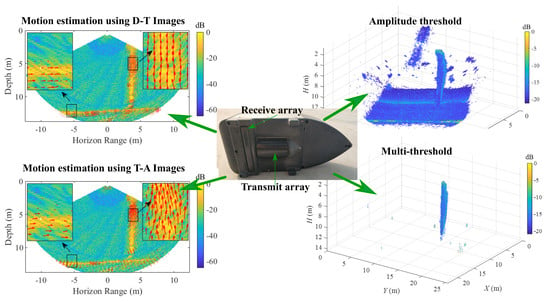
2.2.1. Motion Estimation Using D-T Images

Leaking gases exist in the form of bubble groups in the water column. They diffuse and rise to the surface. These gases result in changes in the intensity distribution in multi-frame WCIs, which can be exploited using the optical flow method to estimate the motion information of the gas emissions. The optical flow calculation [31] uses the variation and correlation of pixel values in two sequential image frames to determine the “motion” of each pixel location. As a basic condition for the application of the optical flow method, it is assumed that the pixel values in the two images satisfy d F ( x , y , t f ) / d t f = 0 , that is:
F ( x , y , t f ) = F ( x + Δ x , y + Δ y , t f + Δ t f )
The generation and extinction of the bubble group, their distribution, and changes in size as they rise will cause rapid changes in the image, which does not occur in sonar images of fixed-shape objects. Therefore, to satisfy the above assumptions, the time interval between frames cannot be too long. Thus, in this paper, when the experimental data is collected in pool and lake, the frame rates of images are 20 Hz and 16 Hz, respectively. Motion information of leaking gasses has been estimated using the Farneback optical flow method, which is a classical dense optical flow estimation algorithm for target motion using images, and its basic principle and implementation are described in detail in [31]. The main idea of this method is to approximate the neighborhood near each pixel of an image as a quadratic polynomial, and to estimate the displacement field of the two frames using a polynomial expansion. Specifically, the neighborhood of each pixel of two images ( F 1 ,   F 2 ) at different times can be approximated as:
{ F 1 ( z ) = z T A 1 z + b 1 T z + c 1 F 2 ( z ) = z T A 2 z + b 2 T z + c 2
where z is coordinate vector of image pixel, parameter A is a symmetric matrix, b is a vector and c is a scalar. It is assumed that F 2 is equal to F 1 with a global displacement d , that is,
F 2 ( z ) = F 1 ( z d )
By using Equation (6) to expand the two functions at both ends of Equation (7) and making the coefficients of the items equal, the global displacement can be obtained. From a visual point of view, an image whose horizontal and vertical axes are represented by the distance is more conducive to directly show the shape of the target. This is also the reason why D-T images are commonly shown in the display and control software of the sonar system rather than T-A images. When the displacement is estimated from two D-T images and divided by the time interval between the two frames, the velocity of each pixel can be obtained. Scheme A of Figure 2 describes a processing flow from beamforming processes of multi-channel echo data to estimate velocity fields and detect targets. The multi-channel echo data are converted into beam space data or a T-A image through the beamforming processing, and then the D-T image can be produced using a coordinate transformation and interpolation.
Some of the methods (e.g., [1,12,17]) to detect gas leaks based on MBESs only used the amplitude/intensity information of D-T images in Scheme A. However, if the detection is only based on amplitude/intensity, it cannot automatically distinguish between strong scatterers such as gas leaks and the seafloor. The motion of rising bubbles was considered [18] to detect leakage via cross-correlation; however, the potential situation of false but large motion speed due to continuous frame changes of the strong backscatter pixels from the seafloor has not been considered. In this paper, two types of information, intensities and velocity vectors, are comprehensively considered, and an automatic detection method for underwater gas leaks is designed to distinguish other strong scatterers in the water such as the seafloor (see Section 2.2.3). Specifically, the D-T images are processed using Farneback optical flow to obtain the velocity vector field.
Furthermore, in Scheme A, all feature information originates from the D-T images; thus, a process of converting from the beam space data to the D-T image is required. For a sonar system with automatic online detection requirements, the serial structure brings with it large hardware costs and affects real-time computing efficiency. For this reason, this paper further proposes the design of a more efficient parallel structure based on beam data. This new structure will affect velocity vector estimation; thus, it is necessary to further derive a corresponding conversion calculation method.

2.2.2. Motion Estimation Using T-A Images

Scheme A in Figure 2 is mainly a serial structure in which stringent requirements are often imposed on the real-time processing capability of the sonar hardware platform. This paper thus proposes Scheme B to directly estimate the motion information of the leaking gases using the T-A image, thereby reducing the processing steps from multi-channel data acquisition to target detection based on velocity. Moreover, the velocity field estimation can be processed in parallel with the D-T image and bathymetric estimation algorithms, instead of relying on serial processes as is done in Scheme A. In Scheme B, the Farneback optical flow method is used to process two frames of the T-A image to obtain relative displacement ( t 0 , θ 0 ) in the direction of echo time and beam angle axis. When the displacement is divided by the time interval, the velocity vector ( u t , v θ ) in the coordinate system with time/orientation as the coordinate axis can be obtained. During the hydrographic surveying, with the fluctuation of the vessel, the sonar array will produce changes in orientation, such as roll and pitch, which will bias the estimated target motion displacement. Fortunately, modern multibeam sonar products usually have roll- and pitch-compensation capabilities, and even medium and deep water MBES can compensate for the heading information, thus avoiding the above-mentioned errors.
The velocity vector ( u t , v θ ) estimated from the T-A images can be used to complete the task of leaking gas detection. There is often a requirement to display velocity information in conjunction with the D-T image. In such cases, it is necessary to convert ( u t , v θ ) into a motion velocity vector ( u x , v y ) with horizontal and vertical displacement per unit time, that is, velocity, as coordinates. Under the T-A image with time-beam angle as the coordinate system, the coordinate transformation of ( t 0 , θ 0 ) can be expressed linearly as:
( t θ ) = ( t θ ) + ( t 0 θ 0 )
Then, the displacement ( x 0 , y 0 ) of the point in the Cartesian coordinate system can be expressed as:
( x 0 y 0 ) = ( c ( t + t 0 ) sin ( θ + θ 0 ) c t sin ( θ ) 2 c ( t + t 0 ) cos ( θ + θ 0 ) c t cos ( θ ) 2 )
where c is the speed of sound at the specified depth of the pixel. Then, ( u x , v y ) can be obtained by the division of ( x 0 , y 0 ) and time interval.

2.2.3. Detection of Gas Emissions

When using the MBES to detect gas emissions, the possible interference sources include sidelobe effects, backscatter contributions from non-gas targets in water (e.g., volume reverberation, seabed reverberation), and background ambient noise, among others [15]. An amplitude threshold can be used to suppress the interference of volume reverberation with low energy contributions. This threshold can be set to a dynamic value varying with the frames, or to a fixed value. The following threshold can be used:
| P ( i , j ) P r e f | > k σ
where P ( i , j ) is the value of each pixel in the WCI, k is the adjustable weight factor, and the values P r e f and σ are the median and standard deviation of all pixel values of the image, respectively. If the pixel in the frame satisfies Equation (10), then it is judged to belong to a part of a leaking gas image; otherwise, the pixel value is eliminated.
For a strong backscattering and relatively static target, the same decision criterion as in Equation (10) can be used, but the data involved in the calculation is replaced by the magnitude of the velocity estimated, that is, V = u x 2 + v y 2 . Furthermore, with regard to the relatively flat seabed topography, when a survey vessel is sailing, the image of the area corresponding to the seabed in WCIs of the adjacent pings will show the partial changes of the energy distribution in the horizontal direction, which is mainly due to the statistical fluctuation of the seabed echo energy caused by the fluctuation of the micro-topography. This phenomenon may also bring about large velocities corresponding to the seabed portion of the velocity field, and most of the velocity direction should be similar to the seabed terrain. In consideration of the above situation, a directional threshold is further set to exclude the target image in the horizontal direction or close to it, in the estimated velocity field. Specifically, in this paper, the threshold on the velocity direction relative to the horizontal is set at 40 degrees. The rising gases may be deflected by currents [4], and thus the range of the velocity direction threshold should be adjusted according to the direction of the ocean current in the sea test. In addition, schools of fish are also common underwater moving targets. Through this direction threshold, some fish school images shown in the horizontal direction can be eliminated.

3. Results

3.1. Pool Experiment

3.1.1. Experimental Design and Equipment

In this study, a scene of leaking gases from a pipeline was simulated in a pool, and the acoustic data was collected by an HT300 PA MBES developed by Harbin Engineering University, China. As shown in Figure 3, the MBES is mainly composed of an underwater subsystem (i.e., the sonar head), an interface unit, and a computer. The underwater subsystem is responsible for the emission, reception, and real-time processing of the underwater acoustic signal. The interface unit is used for real-time information collection of the auxiliary equipment and network data exchange, and the HTCS 3.4 display and control software of this MBES can be operated on a computer. The sonar system emits an acoustic wave with a frequency of 300 kHz, a CW pulse signal with a pulse width of 0.1 ms, and a ping rate of 20 Hz. In addition, its beam width is 2.5° × 1.5° and max swath width is 126°.
The distribution of the bubble size and number of bubbles changes continuously during their rising process because they are affected by factors such as water depth, nozzle size, pressure in the pipeline, flow rate, ocean current, and so on. Also, the backscattering strength (or sound attenuation) of the bubbles is closely related to the signal frequency, bubble size, and the number of bubbles [32,33,34,35]. For a nozzle, its size decides the sizes of bubbles. For example, the radius of the detached bubble could be expressed as a non-monotonic function of the nozzle diameter [36], and the radius showed an increasing trend during the change of the nozzle diameter (0.1 mm–2 mm). For a single bubble, the different sizes correspond to different resonance frequencies, and the backscattering strength reaches a peak at this frequency [35]. The relationship between the scattering cross-section σ and a bubble of a radius a can be expressed as [37]:
σ ( a ) = 4 π a 2 [ ( f 0 f ) 2 1 ] 2 + ( k a ) 2
where f 0 is resonance frequency of the bubble and k is the wave number. This model was applied in [37] to analyze the relationship between backscattering strength and bubble radius at 40 kHz, 180 kHz and 300 kHz. In actual applications, MBESs operate at frequencies from 12 kHz to 400 kHz [3,37], and they have been applied in researching the detection of gas leaks and other targets in water. In general, in shallow water (<200 m), MBESs with a frequency range of 200–400 kHz are usually used for marine surveys, and MBESs with these frequencies are also suitable for the deployment of the unmanned underwater vehicles due to their size. Because the purpose of this paper is to detect underwater pipeline leaks in offshore waters (usually less than 200 m in depth), and comprehensive consideration of factors such as maximum sounding capability, resolution of the multibeam sonar, and frequency response characteristics of the target of interest, this type of MBESs was finally used for experimental research.
During the experiment, the sonar head of the MBES is fixed at 0.5 m below the water surface with a tilt angle of α = 30 ° , as shown in Figure 4. The maximum coverage angle of this MBES is from −63 degrees to +63 degrees and the depth of the pool is shallow; thus, in order to enable the sonar to accurately study the process wherein the bubbles rise to the surface, it is installed vertically with a 30-degree tilt. The leaking gases are generated by an air compressor and released through a long rubber tube, which is connected to the nozzle at the bottom of the pool (5 m depth). Figure 5 is a video capture of the gas leaking scenario during the experiment.

3.1.2. Optical Flow Calculation of the Water Column Images (WCIs) Containing Leaking Gases

Figure 6a,b are D-T images taken via the conventional beamformer (CBF) and the MVDR beamformer, respectively, and both matrix data are normalized and displayed in decibels. The fixed nozzle diameter is ϕ = 0.6   mm ; the output intensity and the output flow rate of the air compressor are 0.1 MPa and 6.3 L/min, respectively; and the sonar head is stationary. In Figure 6a, fan-shaped bright strings are formed at the MSR, and their brightness is close to the intensity level of gas emissions. In this experiment, the gassy release area is designed outside the MSR and its purpose is to consider whether the detection of the gas emissions is still valid when they occur in an area that have significant interference from sidelobe contamination. Figure 6b shows that the image at the MSR (i.e., the region where the sidelobe effect energy is the largest) was well-suppressed. There also is sidelobe leakage outside of the MSR, but the energy level is usually lower than that of the leaking gases.
Using Figure 6b and its adjacent frame images, the motion field distribution of the obtained image region is an implementation of the Farneback optical flow algorithm in MATLAB with Scheme A. In Figure 7a, the estimated velocity field is displayed in conjunction with the WCI of Figure 6b. The direction of the arrow in the figure is indicated as the direction of velocity, and the length of the arrow is the magnitude of the velocity. Since an estimated velocity value can be obtained for each pixel of the D-T image, to avoid a large number of arrows being too dense to observe, the velocity matrix here is subjected to equal interval sampling processing to display. The image of the small frame on the left side in Figure 7a is the enlarged result of the image in the red frame in the gas release zone. Figure 7b shows the estimation results of the leaking gas motion obtained by processing the same data using Scheme B, and the parameters used by the Farneback algorithm are the same as those in Figure 7a. The estimated velocity is converted to the form of ( u x , v y ) for display. Then, Figure 8 shows a set of WCIs and motion field estimation results after changing the experimental conditions, where the nozzle is replaced by one with a diameter of 1.2 mm, the output intensity of pressure is set to 0.5 MPa, and the output flow rate is 51 L/min.
It can be seen from Figure 7 and Figure 8 that the velocity field trends estimated by the two processing schemes are roughly similar, but the calculated velocity field matrices have different distributions in the D-T image. The velocity field data calculated by Scheme A and the individual pixels of the D-T image are sometimes in one-to-one correspondence to their spatial position. However, since the velocity field matrix calculated using Scheme B is equally spaced when using the coordinate system with the beam angle and the TWTT as the coordinate axes, the velocity field data near the sonar head is dense, but gradually becomes sparse as the distance increases. In addition, the velocity field of the region containing gas can be visually different from those of other regions. The direction of the velocity in the region containing gas is mostly in the quasi-vertical direction. Since the sonar head is stationary, the ensonified area on the bottom of the pool has not changed. Under this condition, the energy of the individual pixels corresponding to the bottom area in different ping images changes very little; thus, the estimated velocities in this area will be very small, which can be excluded by considering the magnitude of the velocity.
To quantitatively analyze the consistency of the estimated velocities of the two schemes, a square with a side of 5 cm is selected as an observation area to calculate magnitudes of the velocity at different times in this region. The center point coordinate of the observation area is (5.65 m, 3 m). Figure 9 shows the variation of the average of all the estimated velocities in the observation area, along with the sample time. The horizontal axis is the sample time or the image frame number, and the longitudinal axis is the average of the magnitudes of the velocities. For each pixel, the corresponding magnitude of the velocity can be calculated by V = u x 2 + v y 2 . The curves plotted in Figure 9a,b respectively correspond to the results of the two settings of the nozzle sizes and the output intensities of the pressure conditions, while the data processing is identical. It can be seen from the two figures that the estimated velocity values of the two frames are relatively similar in general, but there are also a small number of different cases. This may be because the number and spatial distribution of velocities estimated by the two frames in the observation area are different. When the difference in velocity values in this area is large, the two statistical averages will show a large deviation. However, this difference does not change the nature of the relatively high-speed movement of the gas emissions from the pipelines, and thus it will not affect the subsequent detection of gas emissions. For leaking gases from undersea pipelines, the velocities of bubbles in water columns were composed of two parts [38]. One is the free rising velocity of the gas bubbles, and the other is the initial velocity when they were ejected at the nozzle. Considering these contributions, the authors of [38] used Doppler shifts of ultrasonic scanning to estimate the leaking gases simulated in the laboratory; the estimated velocity is 3.2–9.7 m/s, which is similar to the results of Figure 9. The echo intensities at different flow rates are further measured and are shown in Figure 10. In the two data acquisitions, the nozzle diameter is always 0.6 mm; the flow rates of the air compressor are 21 L/min and 6.3 L/min, respectively; and the multibeam sonar is set with the same parameters, including the transmit power, fixed gain, and time varying gain. As shown in Figure 10, the large flow rate corresponds to stronger echo intensity as a whole, which is similar to the results found in [37]. This phenomenon implies that there is a certain correlation between the flow rate and the backscattering signal. Compared with results in [39,40], the derived rise velocities in Figure 9 appear on the lower scale. This may be due to the limited output pressure capability of the used air compressor and the absence of currents, which affects the intensity and direction of the motion velocities.

3.1.3. Detection of Gas Emissions

Due to the WCIs and velocity field distributions in the pool experiment, the thresholds of the image amplitudes and velocity values were set according to Equation (10) to detect gas emissions. The weight coefficient of the amplitude threshold is 1, and the weight coefficient of the velocity intensity threshold is 1. By further eliminating the data below the thresholds in Figure 7 and Figure 8, the results can be seen in Figure 11 and Figure 12, respectively. The velocity field data used in Figure 11a, Figure 12a was estimated using Scheme A, while the velocity field data in Figure 11b and Figure 12b were estimated using Scheme B. As can be seen in Figure 11 and Figure 12, the image amplitude and velocity intensity threshold could be used to exclude images with small velocities but strong backscattering.

3.2. Lake Experiment

3.2.1. Experimental Scenario

To quantitatively analyze the estimated velocities of the two schemes under the same conditions, the above-mentioned pool experiment is a static measurement where the relative position of the measuring platform and the gas-releasing device is constant. A dynamic experiment is further designed here to measure the simulated gas emissions from a pipeline using an MBES mounted on a survey vessel. The experimental site is in Songhua Lake, Jilin Province, China, and the MBES and air compressor used in the experiment are the same as in the pool experiment. During the experiment, one end of the rubber tube connecting the nozzles is fixed on a triangular holder seated at a flat bottom of water depth of about 13 m, while the other end is extended from the bottom to a barge on the coast and connected to the air compressor. The fixed nozzle aperture is ϕ = 1   mm and the output intensity of pressure is P o u t = 0.68   MPa . When the survey ship is traveling, the MBES collects the underwater target echo at a ping rate of 16 Hz.

3.2.2. Detection of Gas Emissions

The WCIs in Figure 13 are obtained when the survey ship travels above the leaking gases, and the velocity field distributions of Figure 13a,b are obtained using Schemes A and B, respectively. From the partial enlargement of the two figures, the corresponding velocity field of the regions containing gas is mainly on the upward trend, and the high magnitudes of velocity are also found in the seabed area. However, as analyzed in Section 2.2.3, the velocity field directions in the seabed area are mostly similar to the seabed terrain tendency. Correspondingly, the velocity direction threshold is set to 40 degrees. For instance, the data in Figure 13a are judged only by the amplitude threshold to obtain the detection result as shown in Figure 14a, and the detection result after additional estimation of the magnitude of the velocity and direction threshold is shown in Figure 14b.
It is possible to eliminate pixel data with relatively low intensity, low speed, or high horizontal speeds by comparing Figure 13 and Figure 14 after the detection threshold is set using both the energy and the displacement of the image pixels. Thus, an image with gas emissions can be detected from the complex WCI data.

4. Discussion

In this paper, the motion field in continuous multi-frame WCIs was estimated using an optical flow method. If only the intensity information of each pixel in the WCI is used to detect the leaking gases, the results could detrimentally include the seabed and other strong interference targets in the water column. Although the images of the seabed and sidelobe interference could simply exclude the portion outside the MSR as was done in [12,15], this strategy may also remove parts of the gassy image, and any strong targets suspended within the MSR region cannot be identified and ignored. As shown in Figure 15, only the amplitude threshold was used to detect the WCI data measured on a short survey line in the Songhua Lake. It can be seen from the figure that it is possible to detect other false targets using only the amplitude threshold, thereby affecting the autonomous and high-accuracy recognition of the gas emissions. For this reason, the estimated motion vector information was further used to eliminate the image pixels of relatively low-speed targets or targets whose backscatter is high but moving horizontally, such as a flat seabed or part of a school of fish. Inevitably, small spots of discrete distributions, as shown in Figure 14, may appear after the processing. These spots are mainly residues after the above threshold decision, and they have a low number of pixels with a discrete distribution. Here, these abnormal pixels can be eliminated by a small sliding window. As shown in Figure 16, the three-dimensional morphology of the leaking gases with a relatively clean background was obtained after multi-threshold detection, which achieves the automatic detection of gas emissions. Considering that sidelobe contamination may adversely affect the amplitude and velocity threshold detection, the MVDR beamforming algorithm was used in the beamforming process to suppress the sidelobes.
In addition, two kinds of schemes were designed for data processing. Similar to [18], in Scheme A, the velocity of the movement is estimated from the D-T image, so that the dimension of the velocity vector matrix is consistent with the D-T image, which is more convenient for visual observation. However, considering that the data processing of Scheme A is mainly a serial structure, and the automatic and real-time detection of the leaking gases on the sonar hardware platform is also a potential demand in the future, this paper further proposes directly estimating the gas motion using T-A images and to judge whether the gas emissions are present or not. In this way, the velocity field estimation can be processed in parallel with the D-T image generation and the seabed terrain detection process from the perspective of the data processing flow, and it is not necessary to wait for the conversion of the image from T-A to D-T, which improves the feasibility of real-time realization in the hardware platform of the MBES.
To verify the effectiveness of the proposed method, experiments were carried out on pools and lakes with relatively shallow water depths. The underwater condition may be more complicated with the increase of water depth. For example, the backscattering strength of the bubbles is also related to water depth (or ambient hydrostatic pressure P 0 ). The resonance frequency in Equation (11) can be derived [37] as:
f 0 = 1 2 π a 3 γ P 0 ρ
where ρ is the density of the water, and γ is the ratio of specific heats. It can be seen from the combination of Equations (11) and (12) that the scattering cross section is also a function of the hydrostatic pressure. This is especially the case in deep water conditions, where the effect of hydrostatic pressure is more obvious. Therefore, when the background noise level is isotropic and the leakage rates and sonar frequencies are the same, the signal-to-noise ratio corresponding to the echo of gases at different depths will also change. At this point, the amplitude threshold of Equation (10) should vary with the depth. Therefore, to fully test the detection performance and adjust its adaptability with changes in depth, in future research we will further carry out experimental verification studies in deep water environments. Of course, the rising gases may be deflected by ocean currents [4], and be affected by water density, salinity, temperature, and static pressure, which are important for seismic oceanography [41]. Therefore, the impact mechanism should be further analyzed and the velocity direction threshold adjusted according to the above conditions in sea experiments.
In a pool experiment, the MBES is stationary. When experimenting on the lake, the MBES is installed on the survey vessel and moves along the survey line. With fluctuation of the vessel, the sonar produces changes in orientation, such as roll and pitch, which will bias the estimated target motion displacement. Therefore, when processing the data on the lake, motion attitude information is compensated. In addition, in the pool experiment, the position of the illuminated bottom is unchanged; thus, the fluctuation of the echo from bottom in WCIs of the adjacent pings is very small. When a survey vessel is sailing, the fluctuation shows more significant changes, which is mainly due to statistical fluctuation of the seabed echo energy. Therefore, in terms of the bottom part of the velocity field in Figure 8 and Figure 13, the estimated velocity in the lake experiment appears to be larger than that in the pool experiment.
This paper aims to detect moving targets through high and low-speed fields, without considering the rigorous verification of the accuracy of the estimated speed. This will be considered in subsequent studies, such as using video-in-situ observations [13] for comparison. We will also consider the combination of the backscattering strength of the bubble group to quantitatively estimate the flow rate of the leaking gases. In addition, it is assumed that the seabed terrain is relatively flat when the velocity direction threshold is used. If the terrain changes steeply, the appropriate values of this threshold may be difficult to obtain. Moreover, fish may be one of the major reasons for misdetections, although the direction threshold is set. Therefore, in future research, seabed detection technology will be applied to judge the seabed and eliminate seabed image interference. In addition, other features, such as target shapes, will be considered to eliminate interference from fish.

5. Conclusions

To achieve automatic detection of leaking gases from underwater pipelines, a detection method based on the combination of motion and intensity information of WCI pixels was studied in this paper. The motion of the image pixel was estimated using the Farneback optical flow principle, and two data processing schemes were designed according to two types of WCI data. Through the data analysis of two simulation experiments in a pool and a lake, it can be seen that the velocities obtained based on the above two schemes had relatively good consistency. In addition, after the comprehensive threshold selection using amplitude and velocity information, leaking gases could be detected more efficiently. From the perspective of our designed structure, Scheme B is more suitable for real-time implementation of sonar hardware platforms, while Scheme A is more suitable for execution in display and control software, and in post-processing.
In this paper, it is assumed that the trend of seabed topography is relatively flat in the design of the velocity direction threshold. In future research, bottom-tracking technology will be introduced to judge and eliminate the seabed image with more complex trends of topography, and morphological features will also be introduced to judge and eliminate the other high-velocity motion and strong-backscatter targets in water columns. Moreover, the influence of sound velocity changes for the thresholds will be analyzed.

Author Contributions

C.X., T.Z., and W.Z. developed and designed the experiments; C.X., W.Z., M.W., and W.D. performed the experiments; C.X. and W.Z. analyzed the data; C.X., T.Z., and M.W. wrote the paper, and J.L. and P.R.W. modified and polished the paper. All authors have read and agreed to the published version of the manuscript.

Funding

This research was supported by the National Natural Science Foundation of China (grant numbers U1709203, 41606115 and 41876100), the National Science and Technology Major Project of China (grant number 2016ZX05057005), the National Key R&D Program of China (grant number 2016YFC1402303), and financial assistance from the Postdoctoral Scientific Research Developmental Fund of Heilongjiang (grant number LBH-Q18042). The work of Jianghui Li and Paul R. White was partly supported by the European Union Horizon 2020 research and innovation programme under grant agreement number 654462 (STEMM-CCS).

Acknowledgments

The authors would like to thank Yongxiang Hu and Dongyang Li for their tireless work during the experiment on the lake.

Conflicts of Interest

The authors declare no conflict of interest.

References

  1. Colbo, K.; Ross, T.; Brown, C.; Weber, T. A review of oceanographic applications of water column data from multibeam echosounders. Estuar. Coast. Shelf Sci. 2014, 145, 41–56. [Google Scholar] [CrossRef]
  2. Merewether, R.; Olsson, M.S.; Lonsdale, P. Acoustically detected hydrocarbon plumes rising from 2-km depths in Guaymas Basin, Gulf of California. J. Geophys. Res. 1985, 90, 3075–3085. [Google Scholar] [CrossRef]
  3. von Deimling, J.S.; Weinrebe, W. Beyond bathymetry: Water column imaging with multibeam echo sounder systems. Hydrographische Nachrichten 2014, 31, 6–10. [Google Scholar]
  4. von Deimling, J.S.; Greinert, J.; Chapman, N.R.; Rabbel, W.; Linke, P. Acoustic imaging of natural gas seepage in the North Sea: Sensing bubbles controlled by variable currents. Limnol. Oceanogr. Methods 2010, 8, 155–171. [Google Scholar] [CrossRef]
  5. Nikolovska, A.; Sahling, H.; Bohrmann, G. Hydroacoustic methodology for detection, localization, and quantification of gas bubbles rising from the seafloor at gas seeps from the eastern Black Sea. Geochem. Geophys. 2008, 9, 1–13. [Google Scholar] [CrossRef]
  6. Conti, A.; D’Emidio, M.; Macelloni, L.; Lutken, C.; Asper, V.; Woolsey, M.; Jarnagin, R.; Diercks, A.; Highsmith, R.C. Morpho-acoustic characterization of natural seepage features near the Macondo Wellhead (ECOGIG site OC26, Gulf of Mexico). Deep Sea Res. Pt II 2016, 129, 53–65. [Google Scholar] [CrossRef]
  7. Li, J.; White, P.R.; Bull, J.M.; Leighton, T.G. A noise impact assessment model for passive acoustic measurements of seabed gas fluxes. Ocean Eng. 2019, 183, 294–304. [Google Scholar] [CrossRef]
  8. Li, J.; Roche, B.; Bull, J.M.; White, P.R.; Davis, J.W.; Deponte, M.; Gordini, E.; Cotterle, D. Passive acoustic monitoring of a natural CO2 seep site—Implications for carbon capture and storage. Int. J. Greenh. Gas Control 2020, 93, 102899. [Google Scholar] [CrossRef]
  9. Zhang, W.; Zhou, T.; Peng, D.; Shen, J. Underwater pipeline leakage detection via multibeam sonar imagery. J. Acoust. Soc. Am. 2017, 141, 1. [Google Scholar] [CrossRef]
  10. Hughes Clarke, J.E.; Lamplugh, M.; Czotter, K. Multibeam water column imaging: Improved wreck least-depth determination. In Proceedings of the Canadian Hydrographic Conference, Toronto, ON, Canada, 2–4 June 2006. [Google Scholar]
  11. Innangi, S.; Bonanno, A.; Tonielli, R.; Gerlotto, F.; Innangi, M.; Mazzola, S. High resolution 3-D shapes of fish schools: A new method to use the water column backscatter from hydrographic MultiBeam Echo Sounders. Appl. Acoust. 2016, 111, 148–160. [Google Scholar] [CrossRef]
  12. Urban, P.; Koser, K.; Greinert, J. Processing of multibeam water column image data for automated bubble/seep detection and repeated mapping. Limnol. Oceanogr. Methods 2017, 15, 1–21. [Google Scholar] [CrossRef]
  13. Leblond, I.; Scalabrin, C.; Berger, L. Acoustic monitoring of gas emissions from the seafloor. Part I: Quantifying the volumetric flow of bubbles. Mar. Geophys. Res. 2014, 35, 191–210. [Google Scholar] [CrossRef] [Green Version]
  14. Bayrakci, G.; Scalabrin, C.; Dupre, S.; Leblond, I.; Tary, J.B.; Lanteri, N.; Augustin, J.M.; Berger, L.; Cros, E.; Ogor, A.; et al. Acoustic monitoring of gas emissions from the seafloor. Part II: A case study from the Sea of Marmara. Mar. Geophys. Res. 2014, 35, 211–229. [Google Scholar] [CrossRef]
  15. Zhao, J.H.; Meng, J.X.; Zhang, H.M.; Wang, S.Q. Comprehensive detection of gas plumes from multibeam water column images with minimisation of noise interferences. Sensors 2017, 17, 2755. [Google Scholar] [CrossRef] [PubMed] [Green Version]
  16. von Deimling, J.S.; Brockhoff, J.; Greinert, J. Flare imaging with multibeam systems: Data processing for bubble detection at seeps. Geochem. Geophys. Geosyst. 2007, 8, 7. [Google Scholar] [CrossRef] [Green Version]
  17. Veloso, M.; Greinert, J.; Mienert, J.; De Batist, M. A new methodology for quantifying bubble flow rates in deep water using splitbeam echosounders: Examples from the Arctic offshore NW-Svalbard. Limnol. Oceanogr. Methods 2015, 13, 267–287. [Google Scholar] [CrossRef] [Green Version]
  18. von Deimling, J.S.; Papenberg, C. Technical note: Detection of gas bubble leakage via correlation of water column multibeam images. Ocean Sci. 2012, 8, 175–181. [Google Scholar] [CrossRef] [Green Version]
  19. Blomberg, A.E.A.; Saebo, T.O.; Hansen, R.E.; Pedersen, R.B.; Austeng, A. Automatic detection of marine gas seeps using an interferometric sidescan sonar. IEEE J. Ocean. Eng. 2017, 42, 590–602. [Google Scholar] [CrossRef]
  20. Christoffersen, J.T.M. Multi-detect algorithm for multibeam sonar data. In Proceedings of the OCEANS’13 MTS/IEEE, San Diego, CA, USA, 23–27 September 2013. [Google Scholar]
  21. Wilson, D.S.; Leifer, I.; Maillard, E. Megaplume bubble process visualization by 3D multibeam sonar mapping. Mar. Petrol. Geol. 2015, 68, 753–765. [Google Scholar] [CrossRef]
  22. Best, J.; Simmons, S.; Parsons, D.; Oberg, K.; Czuba, J.; Malzone, C. A new methodology for the quantitative visualization of coherent flow structures in alluvial channels using multibeam echo-sounding (MBES). Geophys. Res. Lett. 2010, 37, 1–6. [Google Scholar] [CrossRef] [Green Version]
  23. Sandsten, J.; Andersson, M. Volume flow calculations on gas leaks imaged with infrared gas-correlation. Opt. Express. 2012, 20, 20318–20329. [Google Scholar] [CrossRef] [PubMed]
  24. Lurton, X. An Introduction to Underwater Acoustics. Principles and Applications, 1st ed.; Springer Praxis Books & Praxis Publishing: London, UK, 2002; pp. 206–209. [Google Scholar]
  25. Clarke, J.E.H. Applications of multibeam water column imaging for hydrographic survey. Hydrogr. J. 2006, 120, 3. [Google Scholar]
  26. Li, H.S.; Gao, J.; Du, W.D.; Zhou, T.; Xu, C.; Chen, B.W. Object representation for multi-beam sonar image using local higher-order statistics. EURASIP J. Adv. Signal Process. 2017, 2017, 7. [Google Scholar]
  27. Du, W.D.; Zhou, T.; Li, H.S.; Chen, B.W.; Wei, B. ADOS-CFAR Algorithm for Multibeam Seafloor Terrain Detection. Int. J. Distrib. Sens. Netw. 2016, 12, 1719237. [Google Scholar] [CrossRef] [Green Version]
  28. de Moustier, C. OS-CFAR detection of targets in the water column and on the seafloor with a multibeam echosounder. In Proceedings of the OCEANS’13 MTS/IEEE, San Diego, CA, USA, 23–27 September 2013. [Google Scholar]
  29. Weng, N.; Li, H.; Yao, B.; Zhou, T.; Wei, Y.; Chen, B.; Liu, X. Tunnel effect in multi-beam bathymetry sonar and its canceling with error feedback lattice recursive least square algorithm. In Proceedings of the MTS/IEEE Kobe Techno-Ocean, Kobe, Japan, 8–11 April 2008. [Google Scholar]
  30. Bai, M.R.; Ih, J.-G.; Benesty, J. Acoustic Array Systems: Theory, Implementation, and Application; Wiley/IEEE Press: Singapore, 2013; pp. 68–76. [Google Scholar]
  31. Farneback, G. Two-frame motion estimation based on polynomial expansion. In Proceedings of the SCIA 2003 13th Scandinavian Conference, Halmstad, Sweden, 2–29 June 2003. [Google Scholar]
  32. Ainslie, M.A.; Leighton, T.G. Review of scattering and extinction cross-sections, damping factors, and resonance frequencies of a spherical gas bubble. J. Acoust. Soc. Am. 2011, 130, 3184–3208. [Google Scholar] [CrossRef]
  33. Ainslie, M.A.; Leighton, T.G. Near resonant bubble acoustic cross-section corrections, including examples from oceanography, volcanology, and biomedical ultrasound. J. Acoust. Soc. Am. 2009, 126, 2163–2175. [Google Scholar] [CrossRef]
  34. Fan, Y.; Li, H.; Xu, C.; Zhou, T. Influence of bubble distributions on the propagation of linear waves in polydisperse bubbly liquids. J. Acoust. Soc. Am. 2019, 145, 16–25. [Google Scholar] [CrossRef]
  35. Fan, Y.; Li, H.; Xu, C.; Chen, B.; Du, W. Acoustic scattering from bubble clouds near the sea surface based on linear oscillations. Acta Acust. 2019, 44, 312–320. [Google Scholar]
  36. Longuet, M.S.; Kerman, B.R.; Lunde, K. The release of air bubbles from an underwater nozzle. J. Fluid Mech. 1991, 230, 365–390. [Google Scholar] [CrossRef]
  37. Greinert, J.; Nutzel, B. Hydroacoustic experiments to establish a method for the determination of methane bubble fluxes at cold seeps. Geo-Mar. Lett. 2004, 24, 75–85. [Google Scholar] [CrossRef]
  38. Wang, J.; Stewart, R.; Dyaur, N. Underwater gas-leak detection and imaging using ultrasonic scanning: Laboratory results. In Proceedings of the 2017 SEG International Exposition and Annual Meeting, Houston, TX, USA, 24–29 September 2017. [Google Scholar]
  39. Clift, R.; Grace, J.R.; Weber, M.E. Bubbles, Drops, Particles; Academic Press: New York, NY, USA, 1978; pp. 169–199. [Google Scholar]
  40. Leifer, I.; Luyendyk, B.P.; Boles, J.; Clark, J.F. Natural marine seepage blowout: Contribution to atmospheric methane. Glob. Biogeochem. Cycles 2006, 20, 1–9. [Google Scholar] [CrossRef]
  41. Dickinson, A.; White, N.J.; Caulfield, C.P. Spatial variation of diapycnal diffusivity estimated from seismic imaging of internal wave field, Gulf of Mexico. J. Geophys. Res. Oceans 2017, 122, 9827–9854. [Google Scholar] [CrossRef] [Green Version]
Figure 1. Examples of T-A and D-T images, and the results of sidelobe effect elimination based on the minimum variance distortionless response (MVDR) beamforming methods [26]. (a,c) are the T-A images, whose ordinates and horizontal coordinates correspond to the beam angle and two-way travel time (TWTT). (b,d) are the D-T images, whose ordinates and horizontal coordinate correspond to vertical depth and horizon range. (a,b) are obtained using a discrete Fourier transformation (DFT) beamforming method, and (c,d) are the processing results via a MVDR beamforming method.
Remotesensing 12 00119 g001
Figure 2. Two types of data processing schemes in motion estimation of gas emissions.
Remotesensing 12 00119 g002
Figure 3. A photograph of HT300 PA MBES.
Remotesensing 12 00119 g003
Figure 4. Schematic diagram of the pool experiment for simulation of leaking gases.
Remotesensing 12 00119 g004
Figure 5. An underwater video screenshot of the bubbles being released.
Remotesensing 12 00119 g005
Figure 6. The WCIs containing gas emissions, obtained by the conventional beamformer (CBF) beamformer (a) and MVDR beamformer (b).
Remotesensing 12 00119 g006
Figure 7. The joint display of the WCI and velocity field estimated by frame A (a) and frame B (b), respectively. The fixed nozzle aperture is ϕ = 0.6   mm and the output intensity of pressure and the output flow rate was 0.1 MPa and 6.3 L/min, respectively.
Remotesensing 12 00119 g007
Figure 8. The joint display of the WCI and velocity field estimated by frame A (a) and frame B (b), respectively. The fixed nozzle aperture is ϕ = 1.2   mm and the output intensity of pressure and the output flow rate are 0.5 MPa and 51 L/min, respectively.
Remotesensing 12 00119 g008
Figure 9. The magnitudes of the velocities estimated from Scheme A and Scheme B. (a) and (b) correspond to the two experimental conditions of Figure 7 and Figure 8, respectively.
Remotesensing 12 00119 g009
Figure 10. Comparison of echo intensities at two flow rate outputs.
Remotesensing 12 00119 g010
Figure 11. Results obtained by screening the data in Figure 7 using thresholds of image amplitude and velocity intensity. (a) and (b) correspond to the processing results of Scheme A and Scheme B, respectively.
Remotesensing 12 00119 g011
Figure 12. Results obtained by screening the data in Figure 8 using thresholds of image amplitude and velocity intensity. (a) and (b) correspond to the processing results of Scheme A and Scheme B, respectively.
Remotesensing 12 00119 g012
Figure 13. The joint display of the WCI and velocity field estimated by frame A (a) and frame B (b), respectively, from the experimental data of a measurement period in Songhua Lake.
Remotesensing 12 00119 g013
Figure 14. The result of the comprehensive detection of the data in Figure 12 using thresholds of pixel intensity, velocity magnitude, and velocity direction. (a) is the detection result using only the amplitude threshold, and (b) is the detection result of adding the magnitude of the velocity and direction threshold.
Remotesensing 12 00119 g014
Figure 15. The result of the amplitude threshold detection of WCI data measured on a short survey line in the Songhua Lake.
Remotesensing 12 00119 g015
Figure 16. The result of the multi-threshold detection of WCI data measured on a short survey line in the Songhua Lake.
Remotesensing 12 00119 g016

