Article

A Lightweight Hyperspectral Image Anomaly Detector for Real-Time Mission

School of Electronics and Information Engineering, Harbin Institute of Technology, Harbin 150080, China
*
Author to whom correspondence should be addressed.
Remote Sens. 2019, 11(13), 1622; https://doi.org/10.3390/rs11131622
Submission received: 29 May 2019 / Revised: 1 July 2019 / Accepted: 3 July 2019 / Published: 8 July 2019
(This article belongs to the Section Remote Sensing Image Processing)

Abstract

:
In real-time onboard hyperspectral-image(HSI) anomalous targets detection, processing speed and accuracy are equivalently desirable which is hard to satisfy at the same time. To improve detection accuracy, deep learning based HSI anomaly detectors (ADs) are widely studied. However, their large scale network results in a massive computational burden. In this paper, to improve the detection throughput without sacrificing the accuracy, a pruning–quantization–anomaly–detector (P-Q-AD) is proposed by building an underlying constraint formulation to make a trade-off between accuracy and throughput. To solve this formulation, multi-objective optimization with nondominated sorting genetic algorithm II (NSGA-II) is employed to shrink the network. As a result, the redundant neurons are removed. A mixed precision network is implemented with a delicate customized fixed-point data expression to further improve the efficiency. In the experiments, the proposed P-Q-AD is implemented on two real HSI data sets and compared with three types of detectors. The results show that the performance of the proposed approach is no worse than those comparison detectors in terms of the receiver operating characteristic curve (ROC) and area under curve (AUC) value. For the onboard mission, the proposed P-Q-AD reaches over 4.5 × speedup with less than 0.5 % AUC loss compared with the floating-based detector. The pruning and the quantization approach in this paper can be referenced for designing the anomalous targets detectors for high efficiency.

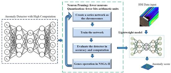
Graphical Abstract

1. Introduction

Due to high spectral and spatial resolution, hyperspectral-image(HSI) has better discrimination performance than traditionally multispectral instruments. Recently, HSI satellites are launched intensively as shown in Figure 1 [1,2,3]. The classification, anomalous target detection (AD) and targets recognition are executed in those missions for precision agriculture, disaster monitor, military mission, and city plan, etc. [4,5,6]. Due to no prior information requirements, anomaly detection is used to find interesting targets which are anomalous targets [7].
In general, an anomalous target is defined as an object or pixel which is different from its surrounding background [8]. Anomalous targets are present in a lower probability than the background, such as a fire point in a forest, oil spill in the sea or a warship in the territorial waters [9]. Timely anomalous target detection can provide an early warning for people to take more operations for safety, security or economy purposes.
To realize a timely early alarm for disaster or military monitor with convincing results, both higher detection accuracy and speed are desired. A series of algorithms are studied for higher accuracy. However, high detection accuracy always leads to high computation complexity. Additionally, traditional HSI anomaly detections are done in the ground. The extra procedures, including image compression, downlink transmission and image decompression greatly increase the response time. Therefore, it is promising to execute the detection onboard along with the image collection.
For onboard detection, the performance of the available computer system is limited by the restrictions on power consumption, mechanical size, heat dissipation, and the harsh space environment. Furthermore, the sharply increased temporal, spectral, and spatial resolution bring more computational burdens to the detector [10]. Therefore, it is significant to decrease the weights of an onboard HSI AD in terms of computation complexity.
To realize the HSI anomalous targets detection, various HSI anomaly detection algorithms have been proposed, such as the Reed–Xiaoli detector (RXD), low probability detection and random-selection-based anomaly detector (RSAD) [11,12,13]. To reduce the processing delay for real-time applications, a various of RXD, such as progressive band processing of anomaly detection (PBP-AD), real-time RX detector, real-time causal RXD (RT-CK-RXD) are proposed [7,14,15]. Those detectors are based on the assumption that the HSI background follows the Gaussian distribution. However, this assumption cannot always be satisfied in real-world and will further increase the false alarm rate. To get a higher detection accuracy, the sparse representation theory based detectors are proposed, such as collaborative representation based anomaly detector (CRD), sparse representation-based detector (SRD), structured sparsity-based anomaly detector [16,17,18,19].
Recently, more deep learning based HSI ADs are proposed to get higher detection accuracy, such as stacked denoising autoencoder (SDAE) anomaly detection, Deep Belief Network (DBN) HSI AD, Weight based stacked-auto-encoder (SAE) HSI AD and transferred deep learning based HSI AD [20,21,22,23,24]. However, the computation requirements of these network are challenging for real-time onboard detection in satellites.
The power, weight, size, and harsh ionizing radiation environment prevent most of the high-performance computing processor in the satellite. Field-programmable gate arrays (FPGA), which are more energy efficient and customizable, have been deemed as better choices for onboard remote sensing images processing [25]. However, there is still a gap between available computing performance in FPGA and the computing requirement of the detection algorithm for real-time onboard detection. In addition, to enhance the computing ability of FPGA, network compression with structure pruning and quantization strategy is a more efficient way by reducing the complexity of the detection algorithm.
To reduce the computation and improve the throughput of a deep learning algorithm on FPGA, quantization and the structured pruning are widely studied recently [26,27]. In general, to learn the high-level non-linear features from the dataset, the deep learning network always set up with redundant connections and neurons. Removing the “unimportant” neurons or weights from a network, the network can compress just with an acceptable accuracy loss [28]. By pruning operation, connection weights with small values are set to zero. The connection matrix becomes sparse. With Huffman coding, the storage capacity for the parameters can be compressed to a small size. However, when the network runs in hardware, an extra design of Huffman decoder or sparse matrix multipliers are required to handle such an irregular operation. In order to facilitate the network accelerated after pruning, the network parameters (channels, filter shapes, and network depth) are considered in loss function which make the network to learn a structured sparsity [29].
Besides structured pruning, quantifying (encoding) the connection weights by fewer bits is another strategy to compress the neural network, namely quantization. In general, arithmetic units with higher data precision (by using more data bit-width) consume more computational resources. Researchers have found that by decreasing the data bit width of the CNN model, the computational amount can be tremendously reduced during an image recognition mission with less accuracy loss [30]. A soft weight-sharing was proposed to implement a quantization on several deep neural networks in classification application with fixed bits number quantization [31]. To balance the accuracy-performance and the compression rates, a multi-bit quantization was proposed based on a weighted-entropy method [32]. To recover the network from a faulty pruning, an in-parallel pruning–quantization was proposed in [33]. Generally, the pruning and the quantization are always implemented together to reduce computation [26].
However, the structured pruning and the quantization approach in supervised image classification cannot be directly applied to the HSI AD mission. To the best of our knowledge, there are no explicit approaches to guide the quantization and structure pruning for onboard HSI AD, while handling anomaly detection accuracy at the same time.
In this paper, to improve the throughput of onboard HSI AD, a pruning–quantization–anomaly–detector (P-Q-AD) is proposed. Network structure pruning and data quantization are executed to create the P-Q-AD with a lightweight network. Due to the throughput is hard to directly evaluated during algorithm design, an algorithm–hardware–cost–factor (AHCF) is defined to indicate the throughput during algorithm optimization. The main contributions of this paper are as follows:
  • To maximize the accuracy and throughput, an underlying relationship between AHCF and detection accuracy is built. It is described as a multi-objective optimization problem (MOP) to explore a probable structure and data width with less anomaly detection accuracy loss.
  • By solving the above MOP with a non-dominated sorting genetic algorithm II (NSGA-II), a P-Q-AD is implemented. In P-Q-AD, to speed up the detection processing, the redundant neurons are removed to shrink the network and a mixed precision network is implemented with a delicate customized fixed-point data expression.
The remainder of the paper is arranged as follows. Common deep learning based HSI AD is introduced briefly in Section 2. In Section 3, the details of the proposed structure pruning, quantization approach are stated. Two real HSI data sets are employed to validate the proposed approach in Section 4 in terms of accuracy and speed.

2. Materials and Methods

2.1. Data Sets

In this paper, the HSI datasets were acquired by the Airborne Visible Infrared Imaging Spectrometer (AVIRIS) for the experiments [34]. The wavelength of the datasets was from 0.4   μ m– 2.5   μ m. We selected 166 spectral bands from the 224 bands after removing the water absorption and low signal-to-noise ration bands with the central frequency of 0.37   μ m– 0.38   μ m, 0.90   μ m– 0.97   μ m, 1.11   μ m– 1.16   μ m, 1.33   μ m– 1.50   μ m and 1.78   μ m– 1.98   μ m [35,36,37].
The first image was captured by AVIRIS file on 28 May 2014. The image file was downloaded from NASA (http://aviris.jpl.nasa.gov/alt_locator/) with the file name as f140528t01p00r10. The spatial resolution of the data set is 16.4 m. Two parts of the first image is used to make the synthetic datasets detector optimization.
The first synthetic dataset was collected over San Jose in United States of America (USA) on 28 May 2014. The image size was 100 × 200 pixels. A series of image blocks with a size of 4 × 4 are used as anomalous targets and embedded in the background. Those anomalous pixels were mixed with 70 % of a ship pixel and 30 % of the background pixels which were replaced by anomalous targets. The colour image and the ground truth image are shown in Figure 2a,b respectively.
The second synthetic dataset was over a hill which is next to the Cloverdale, USA, on 28 May 2014. The image size was 50 × 100 pixels. Three 3 × 3 image blocks of a building pixel were used as anomalous targets. The image blocks were embedded in the background in the same way as the first synthetic data set. The colour image and the ground truth image are shown in Figure 3a,b respectively.
Three HSI datasets are employed in the experiments to evaluate the proposed method in this paper.
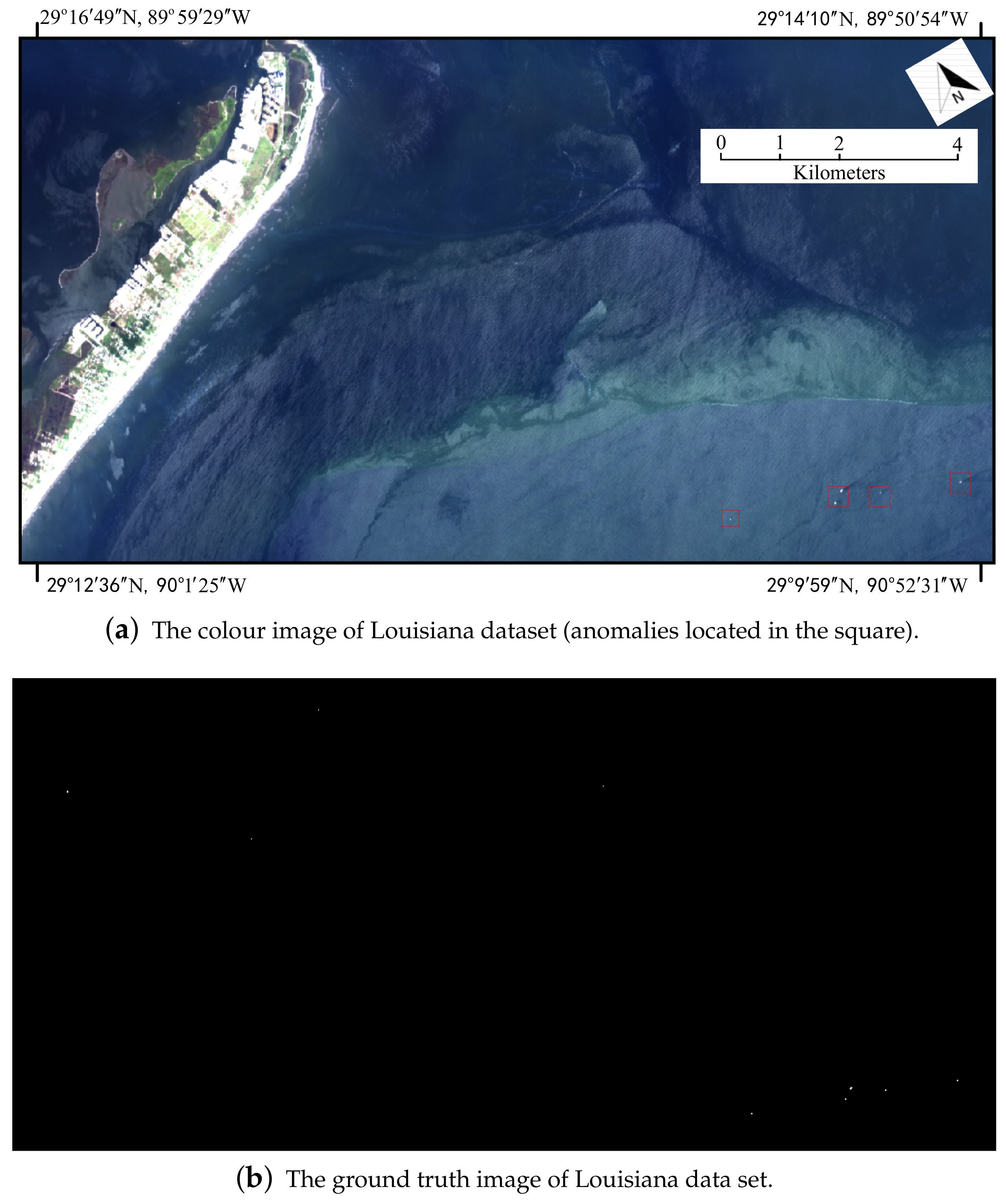
The first dataset was collected at Louisiana in USA on May 24, 2010. The island and the sea were deemed as the background of the dataset. The ships were deemed as the anomalies. The data set is downloaded from National Aeronautics and Space Administration (NASA), file f100524t01p00r09. The data set was with a spatial resolution of 12.2 m per pixel. The colour image and the ground truth image are shown in Figure 4a,b respectively. The locations of some anomalous targets were marked in red squares in Figure 4a.
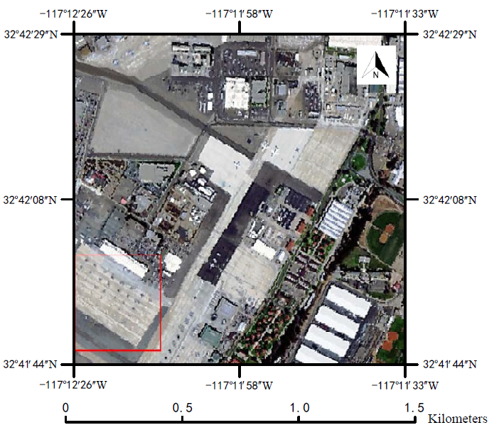
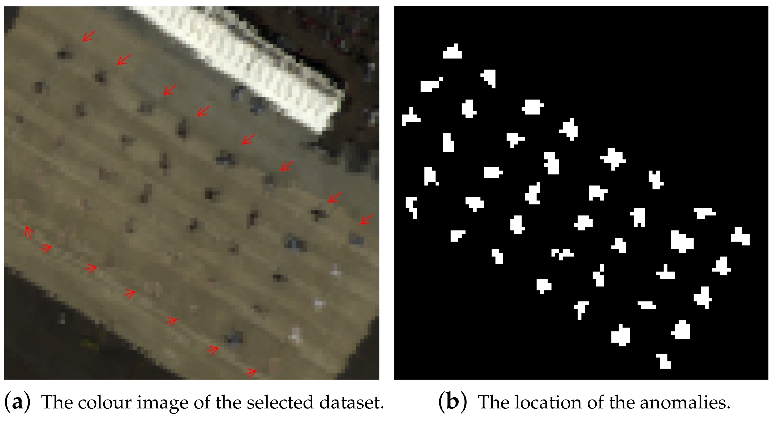
The second dataset was captured over the Sandiego airport in CA, USA. This dataset is with a spatial resolution of 3.5 m per pixel. The colour image of the dataset is shown in Figure 5. The red square with a size of 100 × 100 in Figure 5 was selected as the under test image for the experiment. The color image of this test image is shown in Figure 6a. We deemed 38 planes (partly marked by arrows) as the anomalous objects for the HSI AD. The background objects included roof, ground, road, and Airpark. The ground truth which indicates the location of the anomalies is shown in Figure 6b.
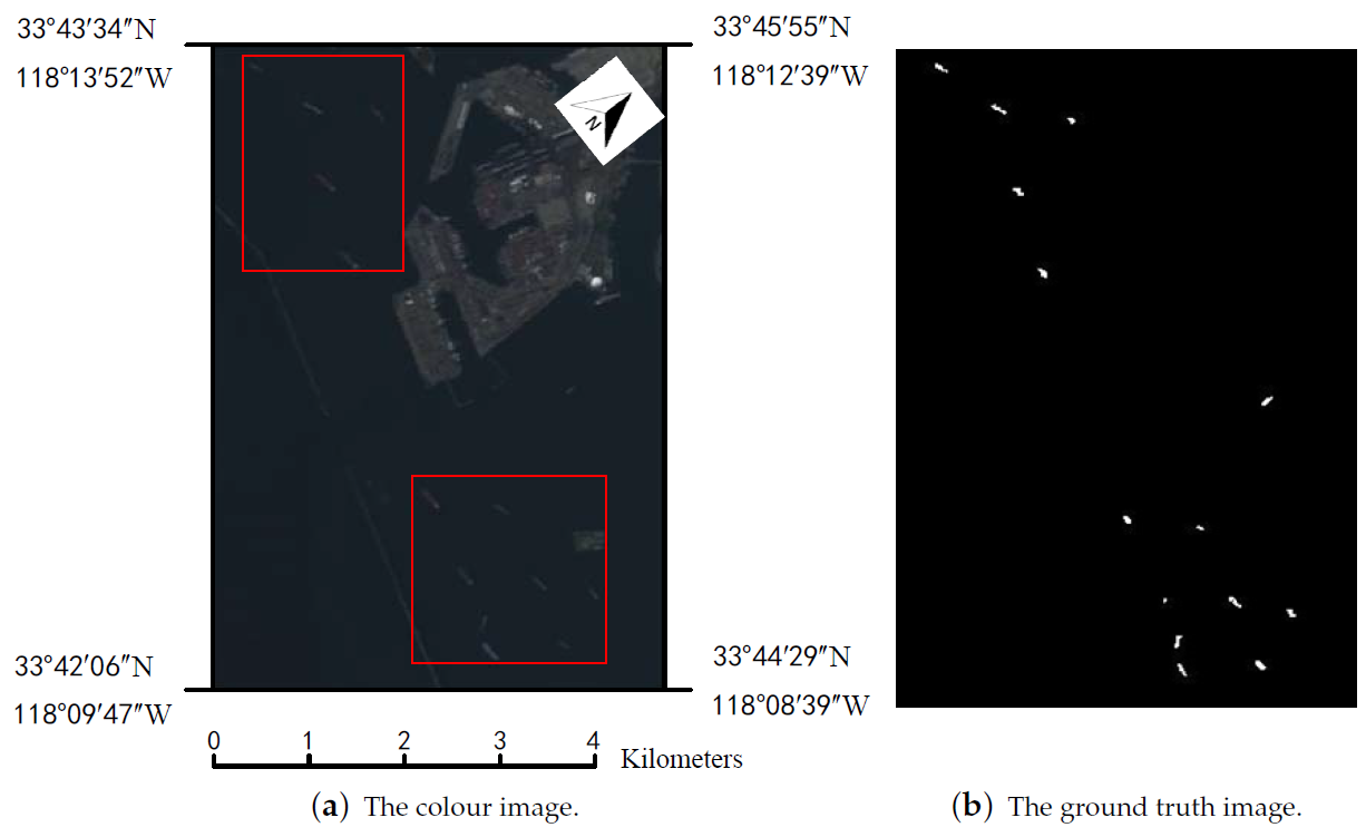
The third data set is collected over Los Angeles in USA on 19 April 2013. This dataset was downloaded from NASA as well. This dataset is with the spatial resolution of 15.6 m per pixel. The filename is f130419t01p00r15. Several ships in the harbor and the sea are regarded as the anomalous targets. Some of the ships are marked in red squares in Figure 7a. The sea and the harbor are regarded as the background. The image size is 430 × 300 . The locations of the anomalies are shown in Figure 7b.

2.2. Deep Learning Based Online HSI AD

Recently, deep learning based methods have developed as a promising technology for HSI anomaly detection. A widely studied network for HSI AD is the multilayer stacked auto-encoder (SAE) which learns the high-level features of the HSI by its abundant non-linear functions. In general, an SAE based HSI AD can be described as Figure 8.
In order to make SAE network representing the features of the HSI image, the SAE network is built by the Model Learning at the first. Due to the anomalous pixel performing less contribution in building the network, the residual of the anomalous pixel is higher than that of the background pixels. Such a residual can be employed to mitigate the local contamination. Then, the HSI image is fed to the SAE network to produce the feature code and the residual of each pixel, namely, inference. With the feature codes and residuals of the image, the distance between pixel under test (PUT) and the background can be measured to generate the anomaly score. Depending on the anomaly score, the anomalous pixels can be determined.
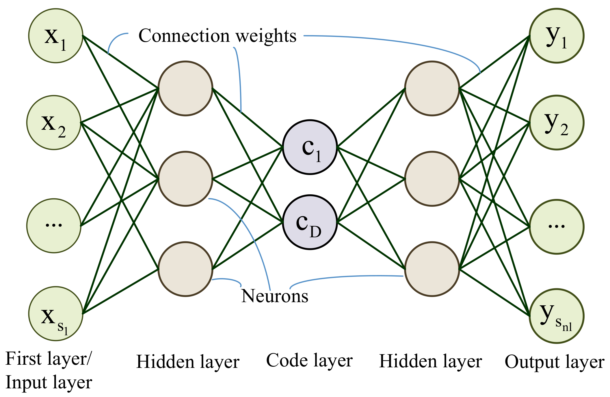
An autoencoder network is stacked by several layers in a symmetrical structure as in Figure 9. The layers are connected together by the connection weights. Through mapping the output similar to the input data to a large extent during the training process, the network can learn the features of HSI in an unsupervised way.
In the Figure 9, the vector x is the input of a hyperspectral pixel for the first layer. The first layer is named input layer. The elements of the x vector are the digital numbers (DN) or reflectance. The layers are constructed by the neurons which are represented by the circles in the Figure 9. The lines between the circles represent the connection weights. The middle layer of the network is constructed with D neurons, and the layer is named code layer in which the output is marked as vector c. The last layer in the Figure 9 is the output layer, and with the output vector y.
As shown in Figure 9, the layers were constructed by the different number of neurons which handle the inputs with a non-linear activation function. In general, the sigmoid function, rectified linear unit (ReLu) function or Leaky Relu function is selected as the activation function. Considering the limitation of the computational resource, the leaky ReLu function is selected for onboard HSI AD mission, which is described as follow [38]:
f ( z ) = z   w h e n   z > 0 ; α · z   w h e n   z 0 ; ,
where z is the input of each neuron. The leaky value is α .
Its derivative is described as follow [38]:
f ( z ) = 1   w h e n   z > 0 ; α   w h e n   z 0 ;
where z is the input of each neuron. The leaky value is α .
In HSI AD application, the number of neurons in the first layer and the output layer are equal to the spectral band number of the HSI. The output of neurons in the ( l + 1 ) -th layer is represented as a ( l + 1 ) or h W , b ( x ) as follows [38]:
z ( l + 1 ) = W ( l ) a ( l ) + b ( l )
h W , b ( x ) = a ( l + 1 ) = f ( z ( l + 1 ) ) ,
where W ( l ) and b ( l ) denote the connection weight and the bias of the l-th layer respectively. Both of them are updated during the training.
The residual between the input pixel x and the network output y is defined as the reconstruction error ξ of the x. The reconstruction error ξ is given as follow:
ξ = x y 2 .
To get the parameters W and b, the model is trained by minimizing the loss function with gradient descent [39]. The loss function is as follow [38]:
J ( W , b ) = 1 2 m i = 1 m h W , b ( x ( i ) ) y ( i ) 2 + λ 2 l = 1 n l 1 i = 1 s l j = 1 s l + 1 W j i l 2 ,
where λ is weight decay parameter, m is the number of training samples, y denotes the decoding output of the network, n l is the total layer numbers of the network, s l is the neuron number of l-th layer.
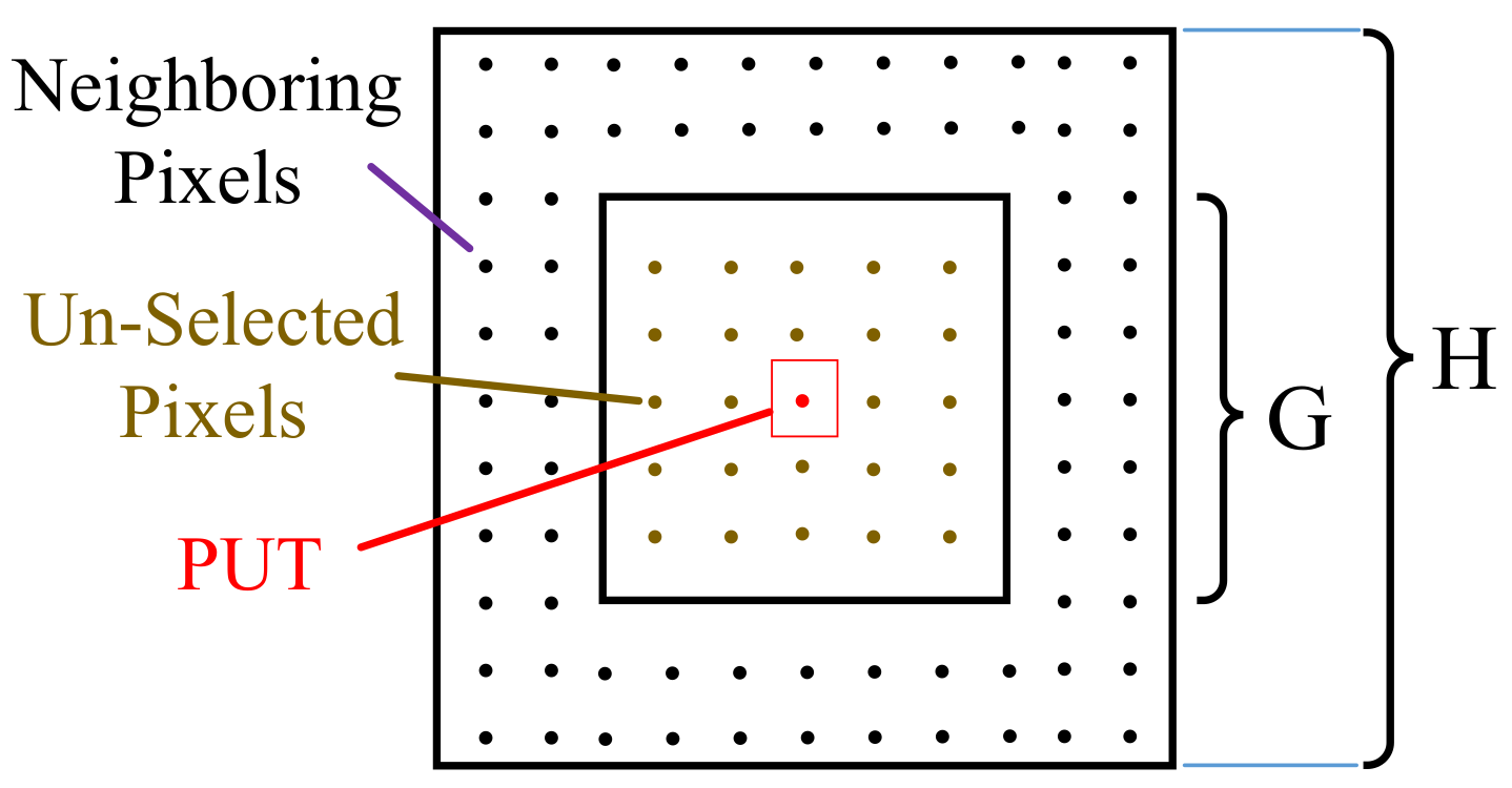
To determine the anomalous pixels, the distances between the PUT and its surrounding pixels were calculated with the output of the neurons in the middle layer. In general, a dual window which slides along with the data generation manner of the camera is employed to determine the location relationship of the PUT and its surrounding pixels [40]. PUT and the surrounding pixels are shown in Figure 10.
In Figure 10, H and G represent the height of the outer and the inner window respectively. The PUT is located in the central of the inner window. To reduce the risk that anomalous pixels are selected as background pixels and participate in anomaly score calculation, the pixels except PUT in the inner window is defined as the Un-Selected pixels which will not attend in the detection. The pixels between the outer and the inner windows are defined as the neighboring pixels which will be used to calculate the anomaly score.
If some anomalous pixels located outside as background pixels, it is called local anomaly contamination. The contamination may lead to a false alarm. To mitigate such contamination, the reconstruction errors from the network are employed to adjust the contribution of each neighboring pixels in the anomaly score calculation. A PUT with a greater anomaly score means that it is more likely to be an anomalous target. The anomaly score is calculated as follow:
δ d = 1 / K j = 1 K 1 ξ j ( i = 1 D x j i y i 2 ) 1 / 2 ,
where K is the total number of local neighboring pixels. ξ j is the reconstruction error of the j-th neighboring pixel, and define in Formula (4).
In the onboard real-time HSI anomaly detection missions, the low delay response and high processing throughput contradict the limitation of onboard computing resources. The computation complexity can be reduced by the network structure pruning. However, the challenge is to keep the detection accuracy when taking those measures.

3. The Pruning-Quantization-Anomaly-Detector

3.1. Basic Analysis for Real-Time Onboard HSI AD

In general, a detector can be designed in two stages: the first one is algorithm design. Improving the throughput of the algorithm in the algorithm design stage is the main work of this paper. The second stage is the hardware implementation in which increasing the chip/device resource utilization and computational performance are general approaches to improve the throughput.
In the algorithm design stage, the throughput is not only related to the neurons number of the network but also depended on the bit-widths of each arithmetic operations. Hence, to improve the detection speed, the redundant neurons and the data bits should be decreased. However, to some extent, the neurons number and the bit-widths may impact the detection accuracy. The speed and accuracy always conflict with each other in a latent relationship. Considering the arithmetic operation can be customized as well as the network, the throughput is not just related to the computation complexity. So, it is difficult to evaluate the throughput for algorithm optimization in the algorithm design stage.
In this section, the AHCF is defined to indicate the throughput in the algorithm design stage. To maximize the detection speed and accuracy, a latent relationship between the objects of throughput and accuracy is built up.
Both objects are related to the factors including neurons number, local window size, leaky value α of the network in Formula (1), and the bit-widths of the arithmetic units. Actually, the above problem is a constrained multi-objective optimization problem. The solution to this problem can be regarded as a multi-objective programming (MOP) problem which is an NP-hard problem. To define the problem, a series of constraining conditions and the objects functions are proposed in the following Section 3.2 and Section 3.3. By solving the MOP with NSGA-II in Section 3.4, the structure pruning, and the data quantization can be implemented for the network of the HSI AD.

3.2. The Detection Accuracy Criterion for MOP

To indicate the detection accuracy, the area under the curve (AUC) value is a commonly used metric. Therefore, the first object is to maximize the AUC value when setting up an HSI AD. The curve is the receiver operating characteristic curve (ROC) which is created by drawing the true positive rate ( T P R ) against the false positive rate ( F P R ) when changing the threshold value for the anomaly score. T P R and F P R are as follows [41]:
T P R = T P T P + F N
F P R = F P F P + T N ,
where T P is the abbreviation of true positive, which is the number of the correctly identified anomalous pixels. F N is the abbreviation of the false negative, which is the number of the incorrectly identified background pixels. F P is the abbreviation of the false positive, which is the number of the incorrectly identified anomalous pixels. T N is the abbreviation of the true negative, which is the number of the correctly identified background pixels.
A greater AUC value means a higher detection accuracy performance of a detector. The AUC value varies between 0 and 1. AUC is as follow [41]:
A U C = T P R ( T ) · F P R ( T ) d T ,
where T is the threshold value.

3.3. The Quantified Detection Speed with Network Structure and Arithmetic Units in Hardware

In this section, the factor which determines the throughput of the detection algorithm is analyzed. Then, the relationship between the detection accuracy and this factor is built to optimize the throughput of the detection algorithm. Because different detection algorithms may be realized with different basic operations which cost different hardware resources in FPGA. If an algorithm requires fewer resources, then a higher throughput can be achieved by implementing multi-parallel copies of the algorithm in the FPGA devices.
To analyze the factors which affect the throughput during the algorithm design stage, we assume there are two detection Algorithms A1 and A2 with C 1 and C 2 number of arithmetic operations respectively for one PUT detection as shown in Figure 11a ( C 1 < C 2 ). Obviously, if the basic arithmetic operators of both algorithms are the same, then algorithm A1 will reach higher throughput than A2 on the same device. However, in the programmable logic, the different basic arithmetic operator may be realized with different type and different amount of hardware resources ( R a or R b in Figure 11), e.g., lookup table (LUT), digital signal processing (DSP) blocks.
In Figure 11, the product of the arithmetic operations amount C and the resources for basic operator R is defined as algorithm–hardware–cost–factor (AHCF) and marked as P C R . The P C R means the resource requirement in theory for the algorithm to detect one PUT with a certain time. This “certain time” is equal to the processing time of one arithmetic operation. In this paper, to simplify the expression, it is defined as the operation cycle.
Assume R a > R b , the P C R of Algorithm A1 and A2 can be expressed as from Figure 11b–e. In Figure 11, there are two relationships between the PCR of Algorithm A1 and A2. In general, P C R ( A 1 ) P C R ( A 2 ) where P C R ( A 1 ) and P C R ( A 2 ) mean P C R of A1and A2 respectively. However, in some situation, the relationship may be P C R ( A 1 ) > P C R ( A 2 ) (when R a · C 1 > R b · C 2 , in Figure 11c,d).
For different P C R , the detection throughput can be analysis from Figure 12.
In Figure 12, the P C R ( A 1 ) and P C R ( A 2 ) are the AHCFs of Algorithm A1 and A2 respectively. Assume P C R ( A 1 ) > P C R ( A 2 ) (even though C 1 < C 2 ). When the available resource of a device is greater than the P C R (Figure 6a,b), the algorithm (A1 or A2) with small P C R can be implemented with more times in the device at the same time and lead to higher detection throughput (six pixels can be detected at the same time in Figure 12b. However, in Figure 12a, it is three pixels).
An instance for the theory throughput analysis on A1 and A2 in an FPGA chip with 300,000 LUTs is shown in Table 1.
In Table 1, we assume that Algorithm A1 require 5000 times multiply and add operation pairs for one PUT detection. Each operation requires 16 LUTs. The AHCF P C R is 80,000 LUTs. Therefore, in the FPGA with 300,000 LUTs, three pixels can be detected at the same time. The resources utilization is 80%. For A2, the AHCF P C R is 45,000 LUTs. We can detect six pixels at the same time with 90% resource utilization. Even though, the device resources utilization in Figure 12b (A2) is higher than that in Figure 12a (A1), the algorithm A2 is better than A1, because A2 produce higher throughput (6 > 3) due to P C R ( A 1 ) > P C R ( A 2 ) (Even though C 1 < C 2 ).
When the available resource of a device is fewer than P C R (as in Figure 12c,d, this situation is common for most of the deep learning applications), the algorithm need be split into several parts to be executed in the device at different time (operation cycles). More operation cycles are required for a bigger P C R and cause lower throughput (two cycles are required for one PUT in Figure 12d, but in Figure 12c it is three cycles). In Figure 12c (A2) and Figure 12d (A1), because of the Algorithm A2 produce high throughput (fewer operation cycles requirement) due to P C R ( A 1 ) > P C R ( A 2 ) , the Algorithm A2 is better than A1 as well.
In this situation, an instance for the theory throughput analysis on A1 and A2 in an FPGA chip with 30,000 LUTs is shown in Table 2.
In Table 2, we assume that for one PUT detection, the Algorithm A1 requires 5000 times multiply-and-add operation pairs, each operation requires 16 LUTs. The AHCF P C R is 80,000 LUTs. In the FPGA with 30,000 LUTs, at least three operation cycles are required to complete one PUT detection. For A2, the AHCF P C R is 45,000, at least two operation cycles are required. Therefore, the throughput of A2 is greater than A1. The resources utilizations of A1 and A2 are not in certain relationship.
Therefore, the throughput is related to the value of the P C R , rather than C. The relationship between throughput and P C R is negative. So, in this paper, the P C R is regarded as the feature to indicate the detection algorithm throughput in the algorithm design stage.
Because of the multiply operation and the add operation are generally appearing in pairs, for the SAE based HSI AD, the multipliers amount is used to represent for the computation operations C which is approximatively quantified by the number of the neurons and the window size as follow:
C = ( H 2 G 2 ) · l = 1 n l 1 s l · s l + 1 ,
where H and G are the local window height and the guard window height respectively, which are shown in Figure 10. According to previous researches, the layers number n l of the network is set as 5 [23]. Due to the symmetrical structure of the autoencoder network, the neurons number of the first and the last layer are equal to the spectral band number B. Therefore, only the neuron number of the second ( n 2 ) and the middle layer ( n m ) are employed as the basic genes. The range of the n 2 and the n m are specified as in Table 3.
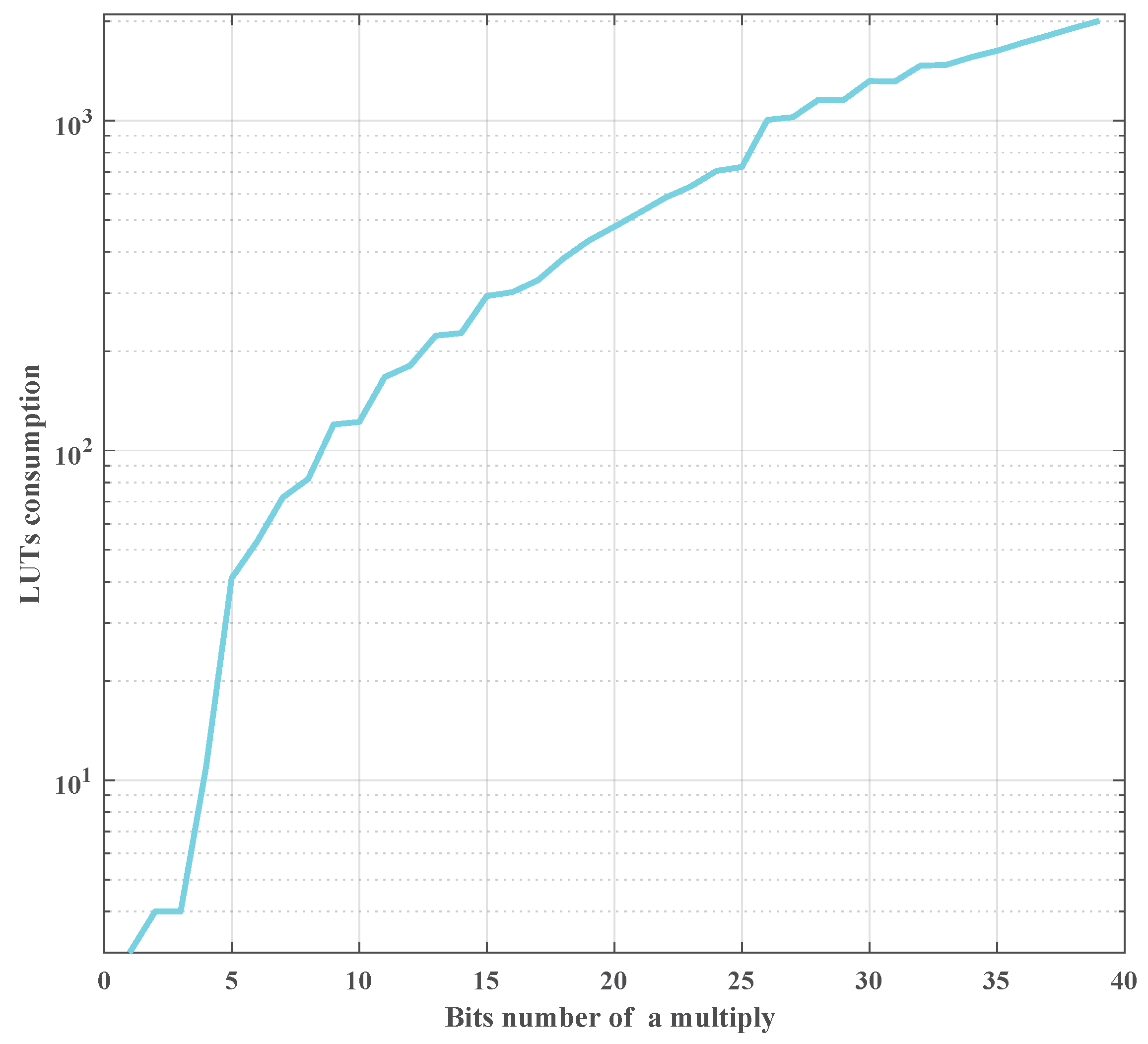
The resource consumption per operation depends on the bit-width of the data. In this paper, the resource consumption per operation is defined as function R ( b l ) , where b l is the data bit-width of the l-th layer in the network. However, the function R ( b l ) is hard to describe with a fixed explicit formulation directly for different kinds of FPGAs. Fortunately, the FPGA type can be fixed for a certain detection mission. In this work, by implementing different bits-width multipliers in a ZYNQ UltraScale device, the resources consumption versus bit-width multiplier is shown in the Figure 13.
An arithmetic operation can be implemented by the DSP elements resources or LUT resources. The input bit-width of the DSPs are fixed in FPGA chips, such as 18 bits or 36 bits. Even if a multiplier with less bit-width operand (<18), it still consumes the whole DSP. Moreover, in an FPGA device, DSPs are fewer than the LUTs. The LUTs are programmable logic resources and can be realized an arbitrarily bit-width multiplier. The LUTs consumption is related to the operand bit-width. For a detection mission, just employing DSPs is not enough to realize arithmetic operations. The LUTs should be used as well. DSPs consumption is less sensitive than LUTs consumption on the different bit-width operand. To simplify the relationship between the resources consumption and the operand bit-width, in this paper, only the LUTs amount is used to represent the resources consumption of arithmetic operation as shown in Figure 13.
In Figure 13, LUTs are shown in logarithmic coordinates. It can be found that the LUTs consumption and the bit-width are in positive correlation. For example, the LUTs consumption of a 40 bits-width multiplier is about 50 times of a five bits-width multiplier. This figure can be used to replace the function R ( b l ) .
Therefore, the P C R of the network can be expressed as follow:
P C R = ( H 2 G 2 ) l = 1 n l - 1 s l · s l + 1 · R ( b l )
where G, H, l, n l , and s l have the same meaning as that in Formula (10). b l is the data bits number of the outputs of l-th layer and the weights between l-th layer and l + 1 -th layer.
To determine the minimum b l without accuracy loss, an error analysis approach was proposed here for the full connection network, which can be extended to other kinds of network easily.
Considering the symmetrical structure of the SAE network in HSI AD, the b l is set in symmetry in term of layer number. For a certain data with b l bits in the decimal bit, its quantization error is described as follow:
ϵ l = 1 2 b l .
To determine the decimal bits number of the b l + 1 with b l , the output of the l-th layer (namely, z ( l + 1 ) in Formula (3a)) can be described as follow:
z j ( l + 1 ) = i = 1 n l a i + ϵ l · W j i l + ϵ l = i = 1 n l a i · W j i l + ( a i + W j i l ) · ϵ l + ϵ l 2 .
Depending on Formula (13), if the quantization error ϵ l + 1 of z j ( l + 1 ) was less than the sum of the last two items (more data bits are required), the quantization error can be ignored. In this paper, to minimize the AHCF ( P C R ), a quantization error in a certain degree was acceptable if the total detection accuracy can be kept. Therefore, the decimal bits number of z j ( l + 1 ) can be deducted as follows:
ϵ l + 1 i = 1 n l ( a i + W j i l ) · ϵ l + ϵ l 2 1 2 b l + 1 i = 1 n l ( a i + W j i l ) · ϵ l + ϵ l 2 b l + 1 lg 2 1 i = 1 n l ( a i + W j i l ) · ϵ l b l + 1 b l lg 2 i = 1 n l a i + W j i l .
Considering the decimal bit analysis and in case of the data overflow, the integer part bit-width ( b l + 1 I = b l + 1 b l + 1 ) of the z ( l + 1 ) can be deducted as follow:
b l + 1 I lg 2 i = 1 n l a i · W j i l + 1 .
To evaluate the statistic characteristics of Formulas (12) and (15), the mean of i = 1 n l a i + W j i l with training dataset in floating point precision was employed in Formula (12) and the maximum of i = 1 n l a i · W j i l is used for Formula (15).
Therefore, the AHCF P C R reduction problem can be described as follows: in the condition of minimizing the loss of detection accuracy, how to find the smallest s l in Formula (10) by structure pruning and how to reduce the b l in conditions as Formulas (13) and (15) by quantization.
Therefore, the latent relationship between detection accuracy and the AHCF P C R can be described as MOP in Formula (16) to prune the network structure and quantify the data precision. The goal of the optimization is to maximize the detection accuracy and minimize the AHCF P C R . The MOP is as follow:
m i n   P C R = ( H 2 - G 2 ) · l = 1 n l - 1 s l · s l + 1 · R ( b l ) m a x   A U C = T P R ( T ) · F P R ( T ) d T s . t .   G < H s 1 = s n l = B s l > s l + 1 , l < n l / 2 s l < s l + 1 , l > n l / 2 b l + 1 = b l + 1 + b l + 1 I b l + 1 b l lg 2 i = 1 n l a i + W j i l b l + 1 I lg 2 i = 1 n l a i · W j i l + 1
where B is spectral bands number of the input HSI. H and G are the local window height and the guard window height. s l is the neurons number of a layer. C is the computational amount as in Formula (10). A U C is the area under the curve which is defined in Formula (9). b l is the bits number of the arithmetic units which connected the outputs of l-th layer and the l + 1 -th layer.

3.4. The Multiobjective Optimization with NSGA-II

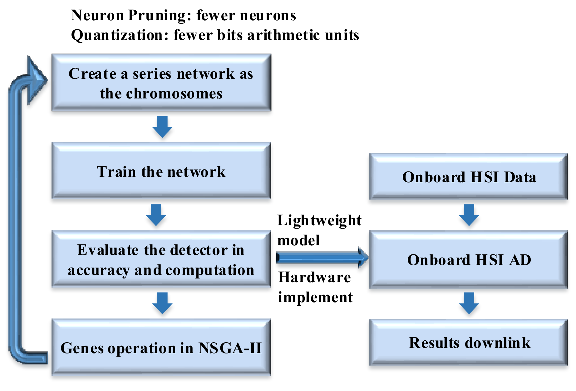
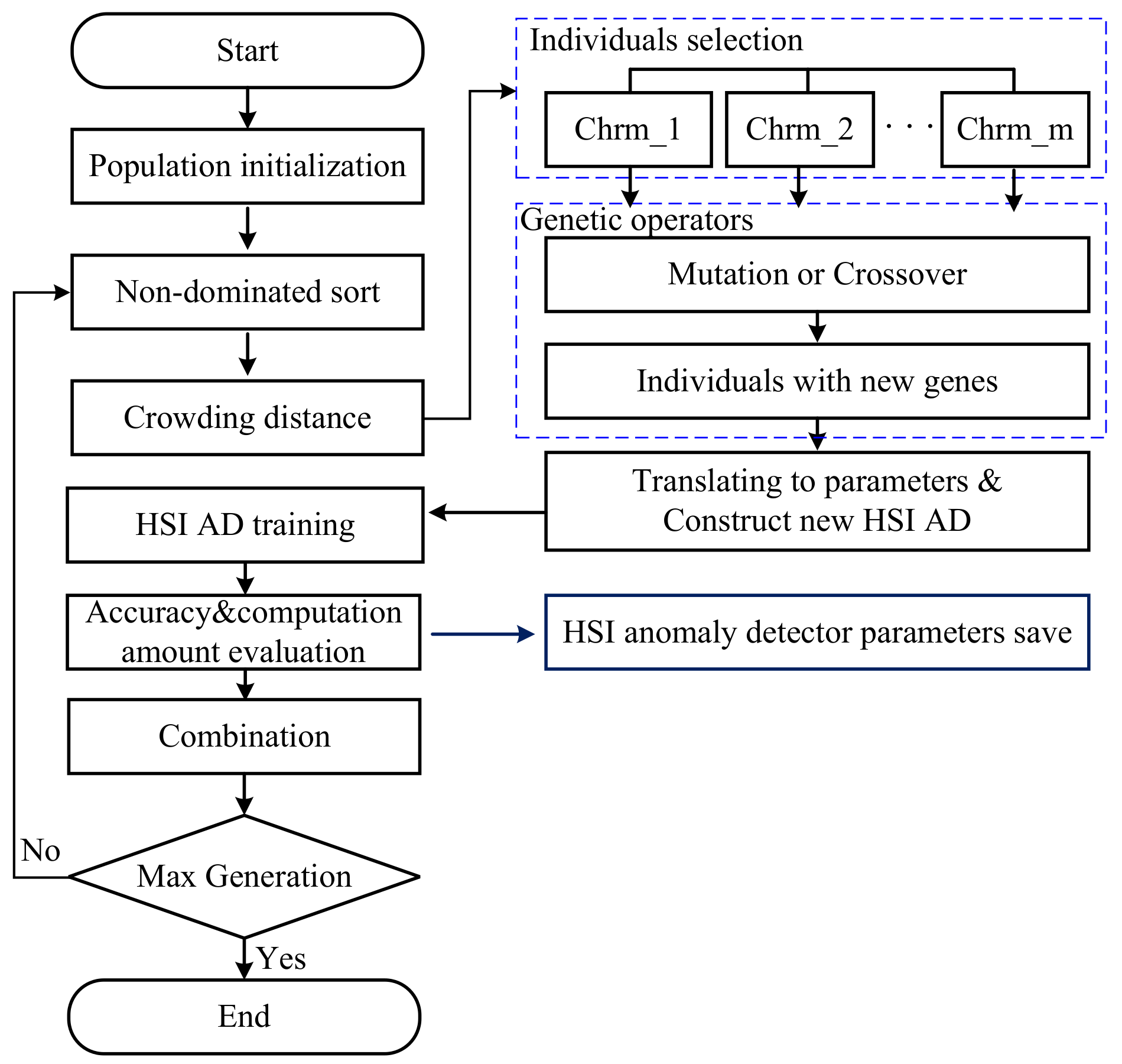
Because the problem in Formula (16) is a non-deterministic polynomial-time hardness (NP-hard) problem, it can not be solved in polynomial time. To solve Formula (16), a genetic algorithm based on the optimization approach named nondominated sorting genetic algorithm II (NSGA-II) is employed in the proposed P-Q-AD to find the optimal solutions [42,43]. The flowchart of the proposed P-Q-AD for onboard HSI AD is shown in Figure 14.
Firstly, the chromosomes are initialized with a developed series of network models for NSGA-II processing. Then, these network models are trained for HSI AD. The AHCF P C R and detection accuracy are evaluated for the corresponding chromosomes. Finally, the genes are updated and the next generation chromosomes are generated according to the evaluation results. If the generation number reaches the maximum value which is set depending on experience(generally, it is set to 200), a lightweight model is generated for hardware implementation. Otherwise, an offspring chromosome will be produced for the next generation. Therefore, the proposed P-Q-AD can be set up and executed on an onboard platform in real time. In onboard HSI AD mission, the HSI data can be directly fed into the detector along with the data collection of the camera. Only the detection results will be transferred to the ground through the downlink.
The parameters, such as neurons number, data bits number, local window size, leaky value α of the network, determine both of the accuracy and the AHCF for an HSI AD as in formula (16). Thus, those parameters are employed as basic genes for the NSGA-II. The range of the basic genes is listed in Table 3. The n m is the neurons number of the middle layer and equals to D. The ranges of the basic genes are set up by experience and listed in Table 3. Because the NSGA-II will be executed to optimize genes value from the ranges in Table 3, a wide range is harmless to the optimization results except for a long optimization searching time (not detection time). Therefore, in this paper, the genes ranges are set wider than the value in our experience. It is necessary to note that, generally, the multiply operation is more complex than the shift operation in FPGAs. More resources or more cycles are generally required for the multiply operation. Thus, to speed up the process, the leaky value is limited to a series of discrete value as that 1 2 k (where k = 0 , 1 , 2 , ). For most of the imaging spectrometers, the data resolutions are ranged from eight bits to 16 bits [34]. Therefore, the maximum data bit-width of the input and the output layer is set as 5 and 16 for integer and the decimal bits ( b 0 I and b 0 ) respectively in case of data overflow.
The basic flow of the NSGA-II is shown in Figure 15. The population is initialized within a specified range as in Table 3. The accuracy and AHCF P C R were used as the fitness function results. The chromosome vector was generated which not only contains the basic genes but also the results of the fitness function and the crowding distance information.
As shown in Figure 15, after the population initialization, a non-dominated sort is executed to rank the individuals depending on the values of the AUC and P C R . With non-dominated sort, the individuals will be divided into several levels of rank.
To preserve the diversity of the parent chromosome, the crowding distance was calculated for each individual. The crowding distance of an individual was the perimeter of a cuboid which vertices are the nearest neighbor individuals in the same rank. Please refer to [43] for more details about the calculation. Then, individuals will be selected as parent individuals for genetic operators.
With genetic operators, individuals with new genes are generated by mutation or crossover operations. Then, the genes of those individuals will be translated into the network structure parameters and the data bit-width of HSI ADs. Those new HSI ADs were trained and evaluated to get their fitness function value including accuracy and AHCF. The fitness values and genes were combined as new individuals.
If the generation number reached to the maximum which is set to 200 in this paper, the optimization were stopped. Otherwise, optimization will be continued to generate a new generation from the non-dominated sort stage. More details about NSGA-II can be found in ref. [42,43].
With NSGA-II, the network of the HSI AD can be built with structure pruning and quantization. Then, the P-Q-AD can be built up as the formula and structure as the description in Section 2.2 and reference [23], the number of neurons and the bit-width of arithmetic operators are determined by the best chromosome with lower P C R and less detection accuracy loss for onboard detection mission.

4. Experiments and Results

4.1. Experiment Environment and Evaluation Criteria

To evaluate the detection accuracy of the proposed approach, the anomaly detectors are implemented on all the datasets for comparison. The first detector is the classic HSI anomaly detector Reed–Xiaoli detector (RXD) which is always used as the baseline algorithm for the HSI anomaly detection research. The second detector is the collaborative representation HSI anomaly detector (CRD) which is recently proposed and products a high accuracy [16].
To evaluate the effect of the proposed approach, the results on all the dataset by four HSI ADs based on SAE network with different operation data precision and the structure are given. Those HSI ADs are floating point precision without pruning (Floating-AD), floating point precision with structure pruning (P-Floating-AD), 32 bits fixed point precision with structure pruning (P-Fixed-AD) and the proposed customized bits fixed point precision with structure pruning (P-Q-AD). The network structure and data precision are given in Table 4.
The proposed network optimization approach and the comparison detectors (LRXD and CRD) are conducted by Matlab 2017a on a Dell T7910 workstation. The workstation contains 2 Intel Xeon CPU with the type of E5-2630 at 2.4 GHz and 32 gigabyte double-data-rate three synchronous dynamic random access memory (DDR3 SDRAM).
The Floating-AD, P-Floating-AD, P-Fixed-AD, and the P-Q-AD run on a heterogeneous SoC platform—ZCU102 which is given in Figure 16 to illustrate the computational efficiency of the onboard mission. The SoC platform contains programmable logic resources (FPGA) and four ARM processors in a single chip.
All algorithms which have been implemented with the same structure by high-level synthesis (HLS). The only difference is the number of neurons and the bit-width. The HLS design aims to maximize the device resource utilization for each algorithm. The optimizations of HLS code are just to make the design work in the pipeline, the optimization sentence is “# HLS PIPELINE II = 1” for the iteration in the matrix multiply in each layer for the proposed algorithm and the comparison algorithms (Floating-AD, P-Floating-AD, P-Fixed-AD). To generate floating-point and different kinds of fixed-point data expression, the following sentences are employed in HLS code. The floating-point and the fixed-point data expression are defined as follow codes:
typedef float T_FX;
typedef ap_fixed < I w b , D w b > T_FX; where I w b and D w b are the numbers of integer and the decimal bits.
The ROC and the AUC were utilized as the criteria to evaluate the accuracy which has been introduced in Section 3. The logic resources utilization and the detection throughputs are also used for performance evaluation.

4.2. Results and Discussion

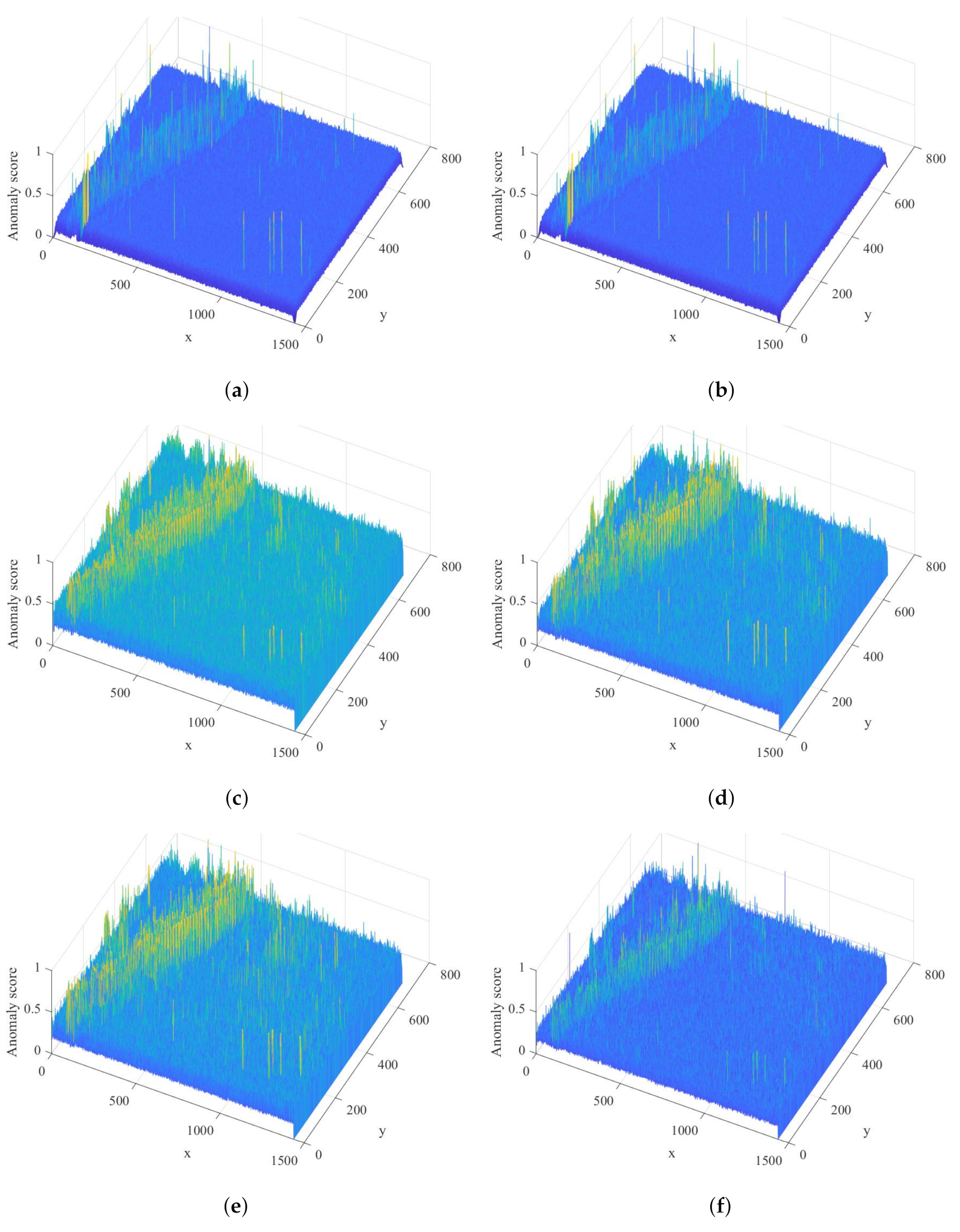
After solving the Formula (16), the proposed P-Q-AD is established with the parameters in Table 4. The detection results for the Louisiana data set by the LRXD, CRD, Floating-AD, P-Floating-AD, P-Fixed-AD, and the proposed P-Q-AD are given in term of anomaly score in Figure 17. A pixel with a greater anomaly score in Figure 17 means it is more likely to be an anomalous pixel.
With the results from the Figure 17, it can be found that the background of the sea is greatly suppressed by the CRD detector. However, some pixels in the island produce great anomaly score by the CRD detector. From the anomaly score by Figure 17c–f, the anomaly score is similar to the anomaly score image from LRXD and CRD. Especially, from the results in Figure 17c,d, after structure pruning, the detector can give almost the same results as the original SAE based detector. Those results prove that the pruning operation can keep the detection accuracy while removing the redundant neurons.
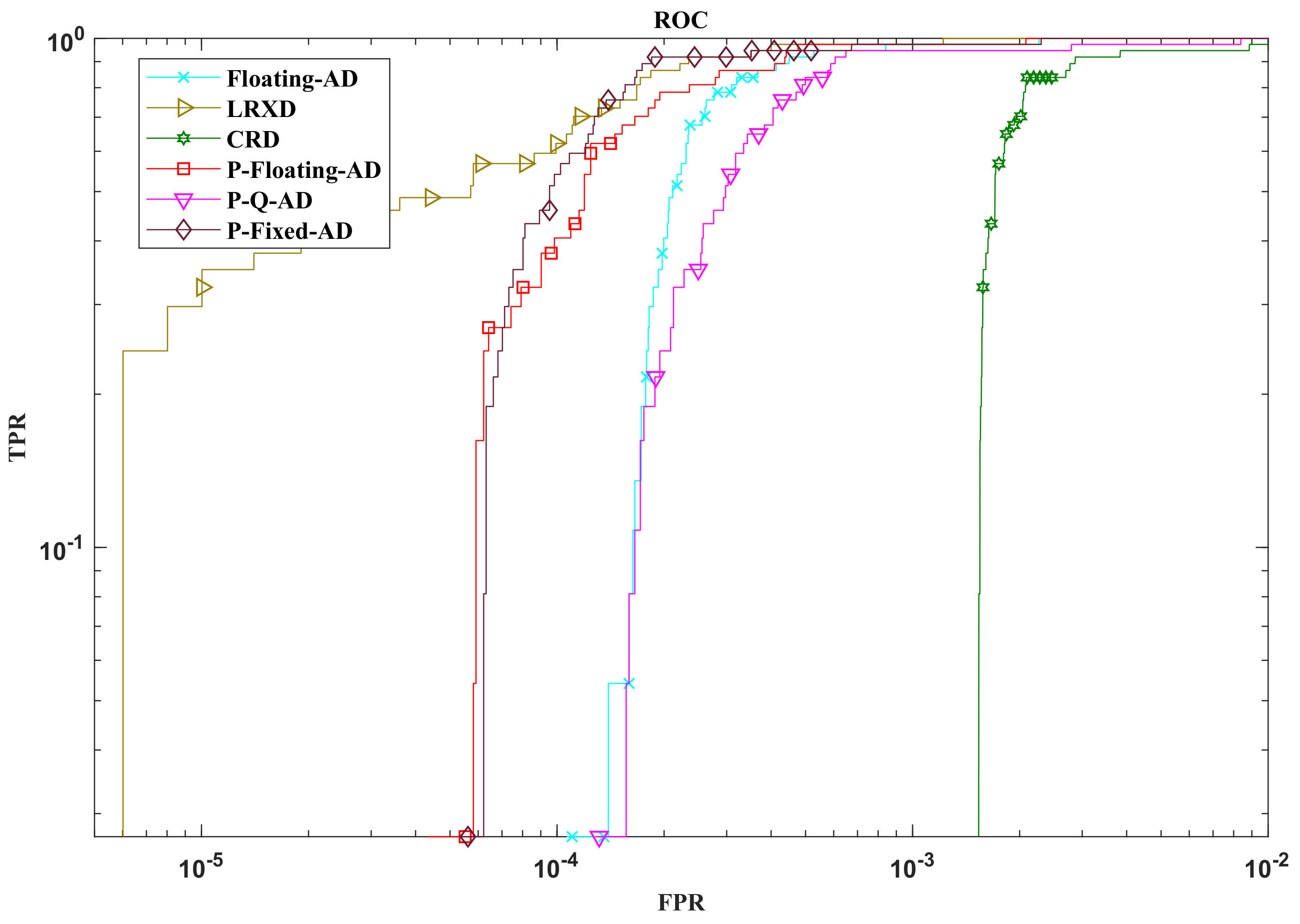
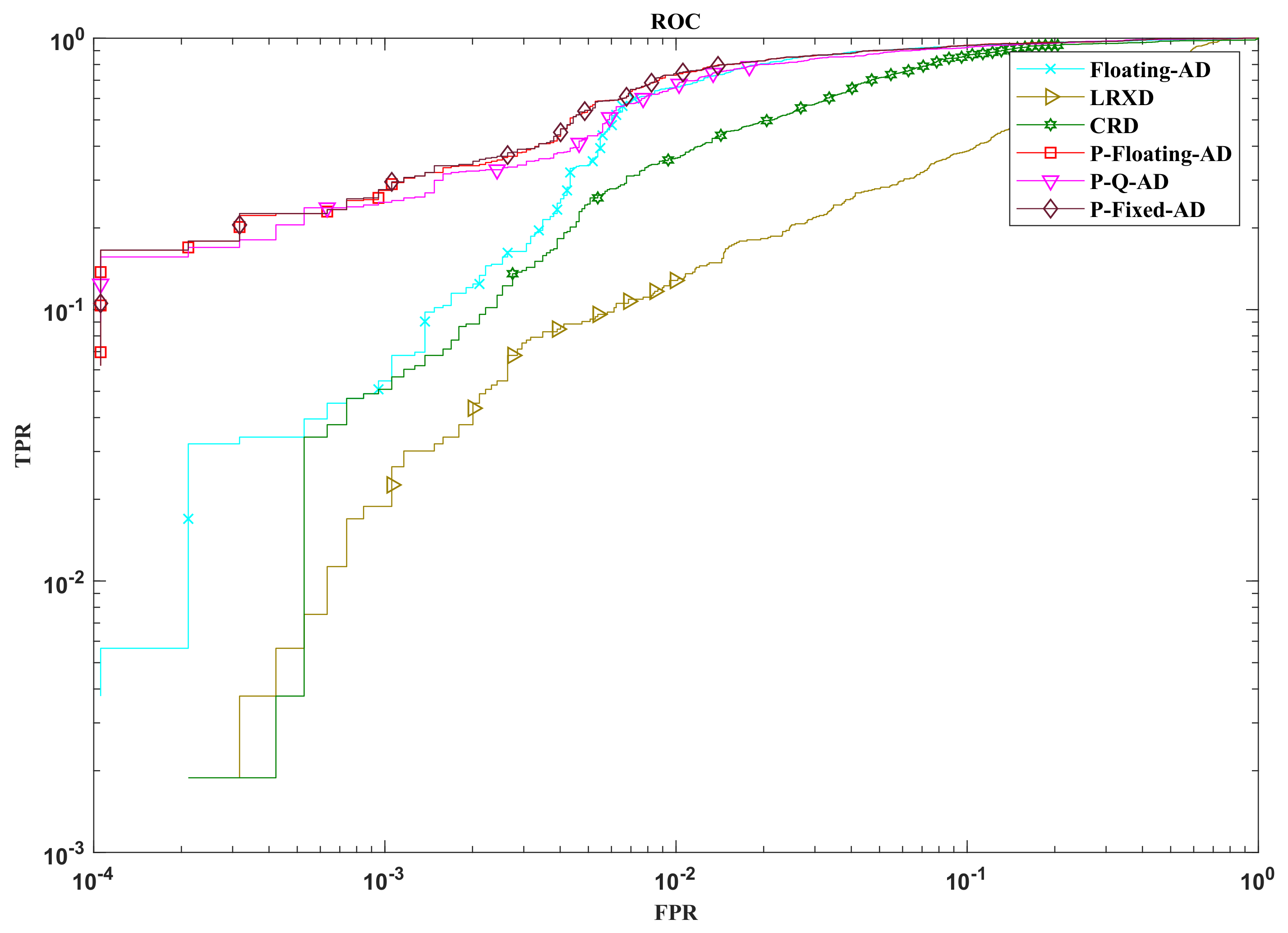
To illustrate the sensitive character in terms of the detection accuracy by the proposed approach, the ROC curves on the Louisiana data set by the LRXD, CRD, Floating-AD, P-Floating-AD, P-Fixed-AD, and the proposed P-Q-AD are shown in Figure 18.
The ROC curves show that the LRXD detector performs well in low false positive rate (FPR < 0.0001). The proposed SAE based detector outperforms CRD in low FPR. It is interesting that after structure pruning (compared to Floating-AD), in low FPR, the detector (P-Floating-AD) performs better. In addition, when quantization the operation precision to 32 bits fixed point, the performance improves in a tiny degree instead of decreasing. As shown in Figure 18, with the efforts of the proposed approach, when pruning the network structure and decreasing the operation precision, P-Q-AD can keep almost the same accuracy with the Floating-AD which is on large scale and with the floating point precision.
To illustrate the impact on the detection accuracy and the throughput by the proposed approach, the AUC values and the detection time on the Louisiana data set by the LRXD, CRD, Floating-AD, P-Floating-AD, P-Fixed-AD, and the proposed P-Q-AD are shown in Table 5. The detection time in Table 5 does not contain the time for initial training and the optimization by NSGA-II which spend over 40 h on the computer. The detection time for LRXD and CRD are based on the T7910 workstation.
From Table 5, the AUC value of each detector conforms their ROCs. If just pruning the network, there is 0.0001 improvement for P-Floating-AD and P-Fixed-AD which are contrary to general expectation. With the proposed pruning and quantization approach at the same time, there was about 0.0003 (about 0.03 % ) AUC loss (P-Q-AD). However, P-Q-AD reaches about 5 × speedup compared to Floating-AD.
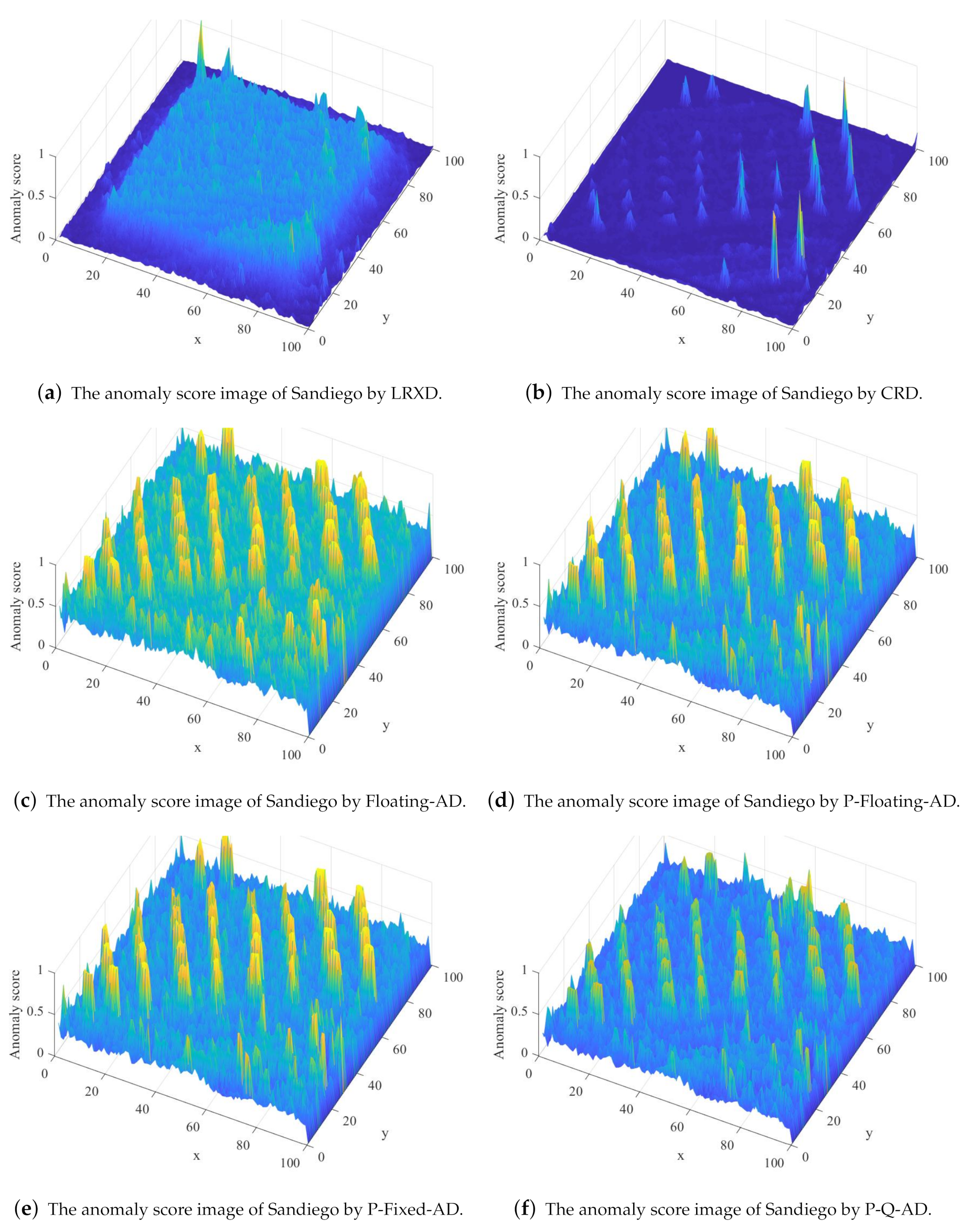
The detection results for Sandiego data set by the LRXD, CRD, Floating-AD, P-Floating-AD, P-Fixed-AD, and the proposed P-Q-AD are given in terms of anomaly score in Figure 19.
From the anomaly score image in the Figure 19a, by LRXD, most of the anomalous targets are detected with small anomaly score and the targets are not clearly shown. From Figure 19b, the CRD suppresses most of the background as the anomaly score from Figure 17b. However, some anomalies are wrongly suppressed and some pixels of a roof are detected with a great anomaly score. The Floating-AD clearly indicate all the anomalous targets as shown in Figure 19c. Comparing Figure 19c–e, with the efforts of the proposed structure pruning, there is no accuracy loss when decreasing the neurons. In all the detectors, there is a cluster false alarm in the left by a vehicle. The vehicle is greatly different from the background and not marked as an anomaly. So, this is a problem by the label according to the definition of the anomalies. Comparing with the floating point based detector, although the accuracy is with a bit lost after data precision quantization (a false alarm is generated besides with an anomalous target), the results by the proposed P-Q-AD still clearly show the targets and get better accuracy than that of CRD and LRXD.
To illustrate the sensitive character in terms of the detection accuracy by the proposed approach, the ROC curves on Sandiego data set by the LRXD, CRD, Floating-AD, P-Floating-AD, P-Fixed-AD and the proposed P-Q-AD are shown in Figure 20.
As shown in Figure 20, the Floating-AD, P-Floating-AD, P-Fixed-AD, and the proposed P-Q-AD outperform the CRD and LRXD. In low FPR (FPR < 0.005 ), the detectors with structure pruning outperform the Floating-AD. Moreover, for the onboard real-time mission, the detectors after quantization and pruning perform better rather than losing the accuracy.
The AUC values and the detection time on the Sandiego data set by the LRXD, CRD, Floating-AD, P-Floating-AD, P-Fixed-AD, and the proposed P-Q-AD are listed in Table 6. The meaning of the detection time in Table 6 does not contain the time for initial training and the optimization by NSGA-II which is run before the detection on the computer.
From Table 6, the P-Floating-AD gets the best accuracy for Sandiego data set. A great number of neurons are deleted with the proposed approach. Due to the data precision reduction, the P-Fixed-AD AUC loss is just about 0.0003 (about 0.032 % ). When the lower precision operation is implemented in P-Q-AD, the AUC value loss is just 0.0041 (about 0.4 % ). Although the accuracy loss is increased, it is still better than LRXD and CRD. It is worth to do the structure pruning and the quantization because it gets about 6 × speed up on Sandiego dataset comparing to Floating-AD.
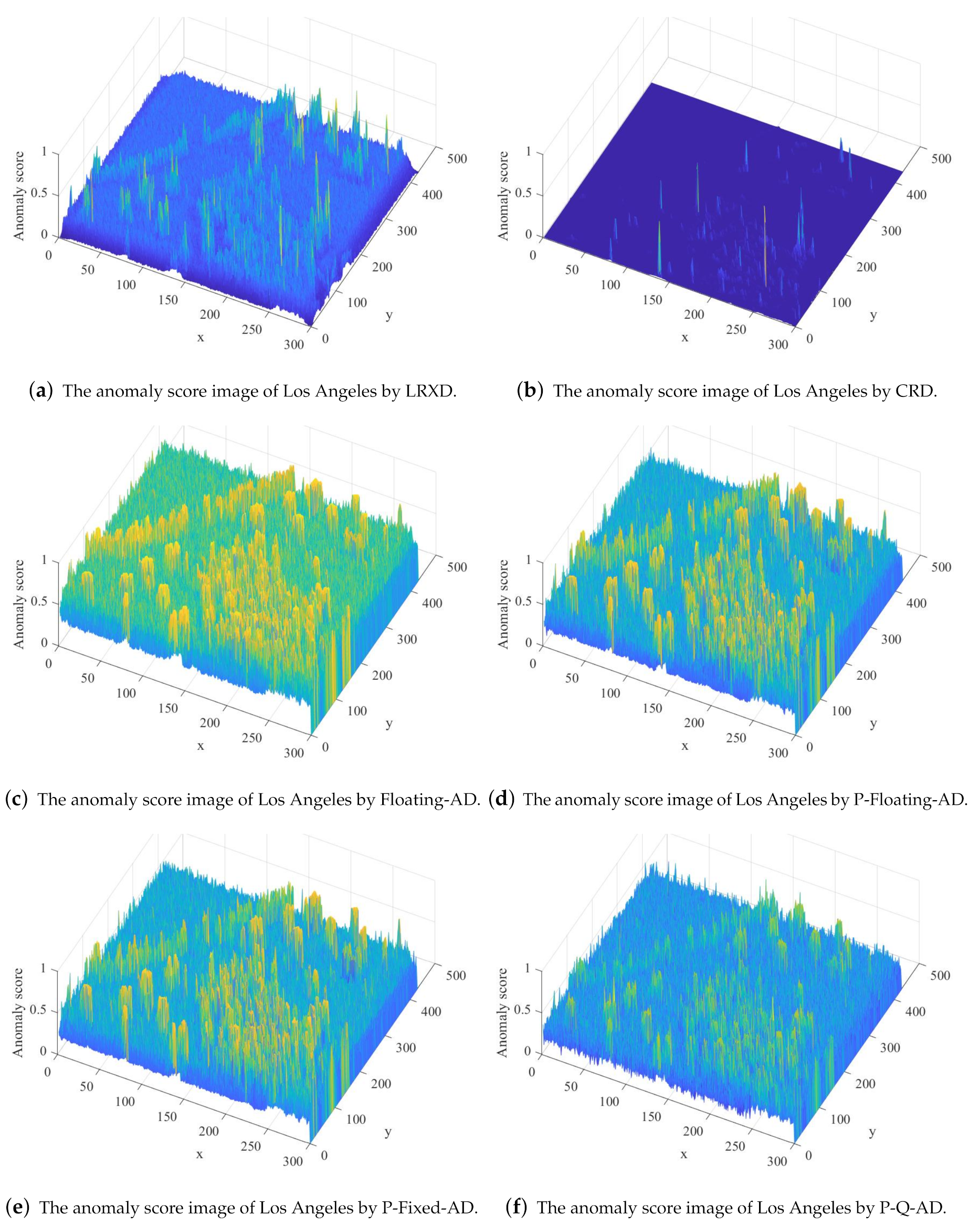
The detection results for Los Angeles data set by the LRXD, CRD, Floating-AD, P-Floating-AD, P-Fixed-AD, and the proposed P-Q-AD are given in term of anomaly score in Figure 21.
From the anomaly score image in the Figure 21a, the anomaly score is fluctuating even for the same anomalous object by the LRXD. The background can be well suppressed by CRD according to Figure 21b. However, similar to the results in the Louisiana data set, some anomalies are wrongly suppressed by the CRD. The Floating-AD, P-Floating-AD, P-Fixed-AD and the proposed P-Q-AD can indicate all the anomalous targets in the Figure 21c–f. Interestingly, after structure pruning and the bit-width quantization, some of the backgrounds can be better suppressed by P-Q-AD than by Floating-AD.
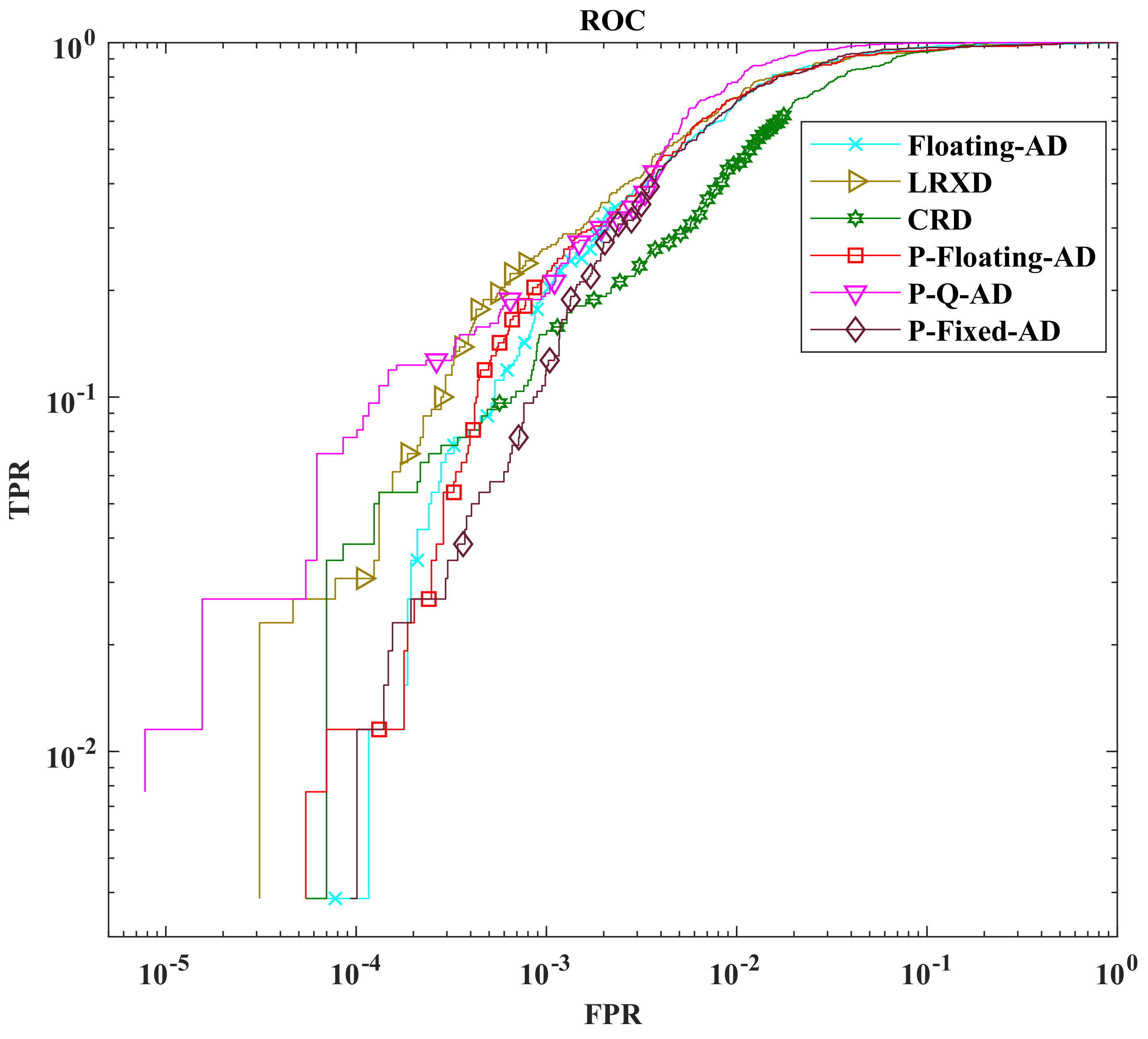
The ROC curves on the Los Angeles data set by the LRXD, CRD, Floating-AD, P-Floating-AD, P-Fixed-AD, and the proposed P-Q-AD are shown in Figure 22.
From the Figure 22, when FPR in the range 3 × 10 - 5 < F P R < 6 × 10 - 5 and the range 10 4 < F P R < 10 3 , the LRXD outperforms other detectors on Los Angeles data set. When F P R > 0.02 , the P-Q-AD performs almost the same detection accuracy with Floating-AD, P-Floating, and P-Fixed-AD, and outperforms LRXD and CRD.
From Table 7, similar to the results on the Sandiego data set, the P-Floating-AD gets the best AUC value for Los Angeles data set. Due to the data precision reduction, the P-Fixed-AD AUC loss is just about 0.0003 (about 0.03 % ).
Even for the lower precision operation by P-Q-AD, the AUC value loss is just 0.0032 (about 0.32 % ). However, with the structure pruning and the bit-width quantization, over 4.5 × speed up is reached on the Los Angeles data set compared with Floating-AD.
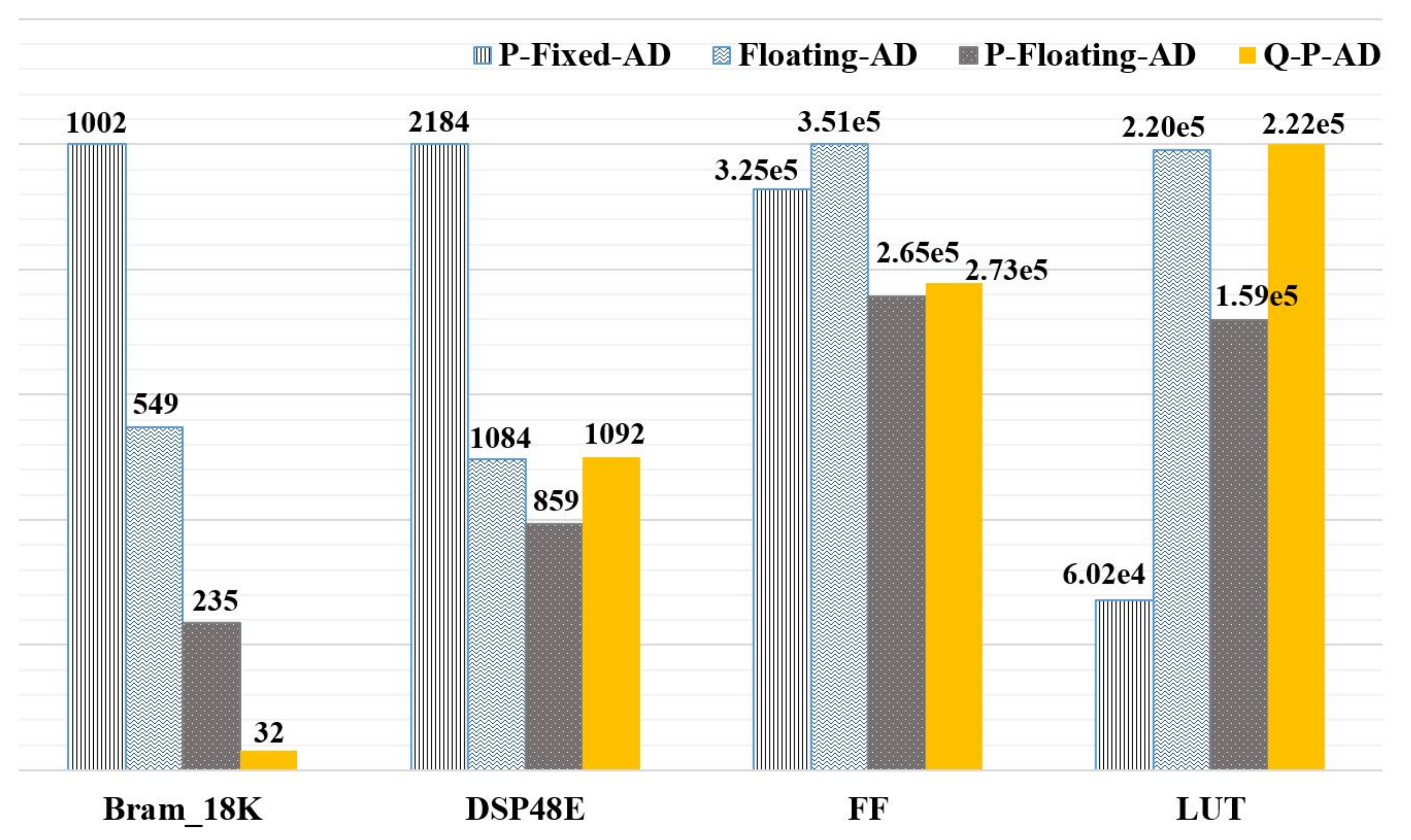
The block random access memory (BRAM_18K), the extension of the digital signal processing (DSP48E), flip-flops (FF), and look-up-table(LUT) are employed to evaluate the computational resource utilization by each detector in Figure 23 as a histogram style. Notice that the goal of the optimization in Section 3.3 is to minimize the AHCF P C R , not the device resource utilization. Actually, as the description in Section 3.1, to increase the throughput in a hardware implementation stage, one of the methods is improving the device resources utilization.
A detection algorithm with a fixed structure and bit-width has a fixed number of arithmetic operations for each PUT. A certain FPGA device provides certain computation resources. Therefore, to maximize the device resource utilization in hardware implementation stage(the second stage, it is not the main contribution of this paper), the computation resources, such as LUTs and DSPs (even DSPs were not considered during optimization network structure and bit-width) are used to realize the detector. The speed of each detector in Figure 23 can be found in Table 5 and Table 6.
From the resources consumption in Figure 23, due to high data precision with more bits for each data, Floating-AD, and the P-Fixed-AD consumes more BRAM_18Ks than P-Q-AD and the P-Floating-AD. With a smaller network structure and lower precision operation, P-Fixed-AD can implement higher parallel design than Floating-AD. However, more weights need to be stored. Thus, it consumes maximum BRAM_18Ks and DSP48E.
For the proposed P-Q-AD, because of fewer bits are used in operations for the network which is implemented by LUT, it consumes fewer DSP48Es for 16 bits operations and more LUTs resources.
From the above experiments results on two real HSI datasets, the proposed P-Q-AD outperforms the base-line detector LRXD and the CRD in terms of detection accuracy and speed. With the proposed structure pruning and data precision quantization approach, the proposed P-Q-AD gets over 4.5 × speedup compared with the Floating-AD under a tiny accuracy loss (<0.5%).

5. Conclusions

To speed up the detection processing for the onboard missions, a P-Q-AD is proposed. The relationship between detection accuracy and speed is set up with a series of constraint formulation. To maximize the detection speed without losing accuracy, the NSGA-II method is adopted to solve the optimization problem. Furthermore, the structure pruning and the data quantization are implemented to reduce AHCF which can help to increase computation parallelism. With the efforts of the proposed approach, the scale of the network is greatly decreased, and the arithmetic operations are simplified to accelerate the detection speed. From the experimental results on two real HSI data sets, the proposed P-Q-AD performs no less than the baseline algorithm LRXD and the CRD in terms of accuracy and speed. By applying structure pruning and the quantization operation, the detector reaches over 4 . 5 × speedup and less than 0 . 5 % accuracy loss compared with the Floating-AD. To some extent, the P-Q-AD in this paper can be regarded as a reference to overcoming the limitation of computation resources in FPGA based onboard anomaly detections.

Author Contributions

All authors assisted in data analysis and manuscript preparation of the paper. N.M. was the main author who contributed to the conception of the study. N.M. and S.W. conceived and designed the experiments, and wrote the manuscript. All authors reviewed and approved the final manuscript.

Funding

This research was funded by Fundamental Research Funds for the Central Universities (Grant No. HIT.NSRIF.201615), Guangxi Key Laboratory of Automatic Detecting Technology and Instruments (YQ15201), and National Natural Science Foundation of China (NSFC, Grants No. 61571160).

Conflicts of Interest

The authors declare no conflict of interest.

References

  1. Yang, C.; Lee, W.S.; Gader, P. Hyperspectral band selection for detecting different blueberry fruit maturity stages. Comput. Electron. Agric. 2014, 109, 23–31. [Google Scholar] [CrossRef]
  2. Weng, Q.; Hu, X.; Lu, D. Extracting Impervious Surfaces from Medium Spatial Resolution Multispectral and Hyperspectral Imagery: A Comparison. Int. J. Remote Sens. 2008, 29, 3209–3232. [Google Scholar] [CrossRef]
  3. Transon, J.; Andrimont, R.; Maugnard, A. Survey of Hyperspectral Earth Observation Applications from Space in the Sentinel-2 Context. Remote Sens. 2018, 10, 157. [Google Scholar] [CrossRef]
  4. Li, X.; Zhang, L.; You, J. Hyperspectral Image Classification Based on Two-Stage Subspace Projection. Remote Sens. 2018, 10, 1565. [Google Scholar] [CrossRef]
  5. Nasrabadi, N.M. Hyperspectral Target Detection. IEEE Signal Process. Mag. 2014, 31, 34–44. [Google Scholar] [CrossRef]
  6. Dong, Y.; Du, B.; Zhang, L.; Hu, X. Hyperspectral Target Detection via Adaptive Information-Theoretic Metric Learning with Local Constraints. Remote Sens. 2018, 10, 1415. [Google Scholar] [CrossRef]
  7. Zhao, C.; Wang, Y.; Qi, B.; Wang, J. Global and Local Real-Time Anomaly Detectors for Hyperspectral Remote Sensing Imagery. Remote Sens. 2015, 7, 3966–3985. [Google Scholar] [CrossRef] [Green Version]
  8. Zhu, L.; Wen, G.; Qiu, S. Low-Rank and Sparse Matrix Decomposition with Cluster Weighting for Hyperspectral Anomaly Detection. Remote Sens. 2018, 10, 707. [Google Scholar] [CrossRef]
  9. Matteoli, S.; Diani, M.; Corsini, G. A Tutorial Overview of Anomaly Detection in Hyperspectral Images. IEEE Aerosp. Electron. Syst. Mag. 2010, 25, 5–27. [Google Scholar] [CrossRef]
  10. Feng, J.; Fang, X.J.; Cao, X.; Ma, C.G.; Dai, Q.H.; Zhu, H.B.; Wang, Y.J. Advanced hyperspectral video imaging system using Amici prism. Opt. Express 2014, 22, 19348–19356. [Google Scholar] [CrossRef] [Green Version]
  11. Reed, I.S.; Yu, X.L. Adaptive multiple-band CFAR detection of an optical pattern with unknown spectral distribution. IEEE Trans. Acoust. Speech Signal Process. 1990, 38, 1760–1770. [Google Scholar] [CrossRef]
  12. Chang, C.I.; Chiang, S.S. Anomaly detection and classification for hyperspectral imagery. IEEE Trans. Geosci. Remote. Sens. 2002, 40, 1314–1325. [Google Scholar] [CrossRef] [Green Version]
  13. Du, B.; Zhang, L. Random-Selection-Based Anomaly Detector for Hyperspectral Imagery. IEEE Trans. Geosci. Remote. Sens. 2011, 49, 1578–1589. [Google Scholar] [CrossRef]
  14. Chang, C.-I.; Li, Y.; Hobbs, M.C.; Schultz, R.C.; Liu, W.-M. Progressive Band Processing of Anomaly Detection in Hyperspectral Imagery. IEEE J. Sel. Top. Appl. Earth Obs. Remote Sens. 2015, 8, 3558–3571. [Google Scholar] [CrossRef]
  15. Chen, S.-Y.; Wang, Y.; Wu, C.-C.; Liu, C.; Chang, C.-I. Real-Time Causal Processing of Anomaly Detection for Hyperspectral Imagery. IEEE Trans. Aerosp. Electron. Syst. 2014, 50, 1510–1533. [Google Scholar] [CrossRef]
  16. Li, W.; Du, Q. Collaborative Representation for Hyperspectral Anomaly Detection. IEEE Trans. Geosci. Remote. Sens. 2015, 53, 1463–1474. [Google Scholar] [CrossRef]
  17. Li, J.; Zhang, H.; Zhang, L.; Ma, L. Hyperspectral Anomaly Detection by the Use of Background Joint Sparse Representation. IEEE J. Sel. Top. Appl. Earth Obs. Remote Sens. 2015, 8, 2523–2533. [Google Scholar] [CrossRef]
  18. Ma, D.; Yuan, Y.; Wang, Q. Hyperspectral Anomaly Detection via Discriminative Feature Learning with Multiple-Dictionary Sparse Representation. Remote Sens. 2018, 10, 745. [Google Scholar] [CrossRef]
  19. Li, F.; Zhang, X.; Zhang, L. Exploiting Structured Sparsity for Hyperspectral Anomaly Detection. IEEE Trans. Geosci. Remote. Sens. 2018, 56, 4050–4064. [Google Scholar] [CrossRef]
  20. Liang, H.; Li, Q. Hyperspectral Imagery Classification Using Sparse Representations of Convolutional Neural Network Features. Remote Sens. 2016, 8, 99. [Google Scholar] [CrossRef]
  21. Zhao, C.; Li, X.; Zhu, H. Hyperspectral anomaly detection based on stacked denoising autoencoders. J. Appl. Remote Sens. 2017, 11, 1–19. [Google Scholar] [CrossRef]
  22. Ma, N.; Wang, S.; Yu, J.; Peng, Y. A DBN based anomaly targets detector for HSI. In Proceedings of the Aopc 2017: 3D Measurement Technology for Intelligent Manufacturing, Beijing, China, 4–6 June 2017; Volume 10458, pp. 1–6. [Google Scholar] [CrossRef]
  23. Ma, N.; Peng, Y.; Wang, S.; Gao, W. A weight SAE based hyperspectral image anomaly targets detection. In Proceedings of the International Conference on Electronic Measurement & Instruments (ICEMI), Yangzhou, China, 20–22 October 2017; pp. 511–515. [Google Scholar] [CrossRef]
  24. Li, W.; Wu, G.; Du, Q. Transferred Deep Learning for Anomaly Detection in Hyperspectral Imagery. IEEE Geosci. Remote Sens. Lett. 2017, 5, 597–601. [Google Scholar] [CrossRef]
  25. Lopez, S.; Vladimirova, T.; Gonzalez, C.; Resano, J.; Mozos, D.; Plaza, A. The Promise of Reconfigurable Computing for Hyperspectral Imaging Onboard Systems: A Review and Trends. Proc. IEEE 2013, 101, 698–722. [Google Scholar] [CrossRef]
  26. Han, S.; Mao, H.; Dally, W.J. Deep Compression: Compressing Deep Neural Networks with Pruning, Trained Quantization and Huffman Coding. arXiv 2015, arXiv:1510.00149. [Google Scholar]
  27. Fujii, T.; Sato, S.; Nakahara, H. A Threshold Neuron Pruning for a Binarized Deep Neural Network on an FPGA. IEICE Trans. Inf. Syst. 2018, 101, 376–386. [Google Scholar] [CrossRef]
  28. Cun, Y.L.; Denker, J.S.; Solla, S.A. Optimal brain damage. In Proceedings of the International Conference on Neural Information Processing Systems, Denver, CO, USA, 27–30 November 1989; pp. 598–605. [Google Scholar]
  29. Wen, W.; Wu, C.; Wang, Y.; Li, H. Learning Structured Sparsity in Deep Neural Networks. In Advances in Neural Information Processing Systems; NIPS: Grenada, Spain, 2016; pp. 2074–2082. [Google Scholar]
  30. Han, S.; Pool, J.; Tran, J.; Dally, W.J. Learning both Weights and Connections for Efficient Neural Networks. In Proceedings of the 28th International Conference on Neural Information Processing Systems (NIPS), Montreal, QC, Canada, 7–12 December 2015; pp. 1–9. [Google Scholar]
  31. Ullrich, K.; Welling, M. Soft weight-sharing for neural network compression. arXiv Preprint 2017, arXiv:1702.04008. [Google Scholar]
  32. Park, E.; Ahn, J.; Yoo, S. Weighted-entropy-based quantization for deep neural networks. In Proceedings of the IEEE Conference on Computer Vision and Pattern Recognition, Honolulu, HI, USA, 21–26 July 2017; pp. 7197–7205. [Google Scholar] [CrossRef]
  33. Tung, F.; Mori, G. Deep Neural Network Compression by In-Parallel Pruning-Quantization. IEEE Trans. Pattern Anal. Mach. Intell. 2018, 1–12. [Google Scholar] [CrossRef] [PubMed]
  34. Hamlin, L.; Green, R.O.; Mouroulis, P.; Eastwood, M. Imaging Spectrometer Science Measurements for Terrestrial Ecology: AVIRIS and the Next Generation AVIRIS Characteristics and Development Status. IEEE Aerosp. Conf. Proc. 2011, 1–7. [Google Scholar] [CrossRef]
  35. Curran, P.J.; Dungan, J.L. Estimation of signal-to-noise: a new procedure applied to AVIRIS data. IEEE Trans. Geosci. Remote. Sens. 1989, 27, 620–628. [Google Scholar] [CrossRef]
  36. Gao, B.C.; Heidebrecht, K.B.; Goetz, A.F.H. Derivation of scaled surface reflectances from AVIRIS data. Remote. Sens. Environ. 1993, 44, 165–178. [Google Scholar] [CrossRef]
  37. Rodger, A.; Lynch, J.M. Determining atmospheric column water vapour in the 0.4–2.5 μm spectral region. In Proceedings of the AVIRIS Workshop, Pasadena, CA, USA, 27 February–2 March 2001; Jet Propulsion Laboratory (JPL) Publication: Pasadena, CA, USA, 2001. [Google Scholar]
  38. Goodfellow, I.; Bengio, Y.; Courville, A. Deep Learning; MIT Press: Cambridge, MA, USA, 2016; pp. 499–522. [Google Scholar]
  39. Hinton, G.; Osindero, S.; Teh, Y. A fast learning algorithm for deep belief nets. Neural Comput. 2006, 7, 1527–1554. [Google Scholar] [CrossRef] [PubMed]
  40. Soofbaf, S.R.; Sahebi, M.R.; Mojaradi, B. A Sliding Window-Based Joint Sparse Representation (SWJSR) Method for Hyperspectral Anomaly Detection. Remote Sens. 2018, 10, 434. [Google Scholar] [CrossRef]
  41. Fawcett, T. An introduction to ROC analysis. Pattern Recognit. Lett. 2006, 27, 861–874. [Google Scholar] [CrossRef]
  42. Ramesh, S.; Kannan, S.; Baskar, S. Application of a fast and elitist multi-objective genetic algorithm to Reactive Power Dispatch. Serbian J. Electr. Eng. 2009, 6, 119–133. [Google Scholar] [CrossRef]
  43. Deb, K.; Pratap, A.; Agarwal, S.; Meyarivan, T. A fast and elitist multiobjective genetic algorithm: NSGA-II. IEEE Trans. Evol. Comput. 2002, 6, 182–197. [Google Scholar] [CrossRef] [Green Version]
Figure 1. Lifetime of the main multispectral imagers sensors and the hyperspectral-image (HSI) sensor in past and plan [3].
Remotesensing 11 01622 g001
Figure 2. The colour image and the ground truth image of Sanjose data set.
Remotesensing 11 01622 g002
Figure 3. The colour image and the ground truth image of Cloverdale data set.
Remotesensing 11 01622 g003
Figure 4. The colour image and the ground truth image of Louisiana data set.
Remotesensing 11 01622 g004
Figure 5. The colour image of Sandiego airport HSI dataset.
Remotesensing 11 01622 g005
Figure 6. The colour image and the ground truth image of Sandiego data set.
Remotesensing 11 01622 g006
Figure 7. The colour image and the ground truth image of Los Angeles data set.
Remotesensing 11 01622 g007
Figure 8. An stacked-auto-encoder (SAE) based HSI anomaly detector (AD).
Remotesensing 11 01622 g008
Figure 9. The structure of a common deep learning based HSI AD.
Remotesensing 11 01622 g009
Figure 10. The location relationship between pixel under test (PUT) and surrounding pixels.
Remotesensing 11 01622 g010
Figure 11. The computation amount and the algorithm-hardware-cost-factor (AHCF) with different R. (a) Computation amount of two different algorithms. (b) A small algorithm implemented by the operations with less hardware resources. (c) A big algorithm implemented by the operations with less hardware resources. (d) A small algorithm implemented by the operations with huge hardware resources. (e) A big algorithm implemented by the operations with huge hardware resources.
Remotesensing 11 01622 g011
Figure 12. The analysis of throughput and the AHCF in device. (a) The implementation of a big P C R algorithm in an abundant resources device. (b) The implementation of a small P C R algorithm in an abundant resources device. (c) The implementation of a big P C R algorithm in an insufficient resources device. (d) The implementation of a small P C R algorithm in an insufficient resources device.
Remotesensing 11 01622 g012
Figure 13. The lookup table (LUT) consumption of the multiply in different bits number.
Remotesensing 11 01622 g013
Figure 14. The flowchart of the proposed pruning–quantization–anomaly–detector (P-Q-AD) for onboard HSI AD.
Remotesensing 11 01622 g014
Figure 15. The basic flow of the NSGA-II.
Remotesensing 11 01622 g015
Figure 16. The ZCU102 platform.
Remotesensing 11 01622 g016
Figure 17. The detection results for Louisiana data set. (a) The anomaly score image of Louisiana by LRXD; (b) The anomaly score image of Louisiana by collaborative representation based anomaly detector (CRD); (c) The anomaly score image of Louisiana by floating point precision without pruning anomaly detectors (Floating-AD); (d) The anomaly score image of Louisiana by floating point precision with pruning anomaly detectors (Floating-AD)P-Floating-AD; (e) The anomaly score image of Louisiana by P-Fixed-AD; (f) The anomaly score image of Louisiana by P-Q-AD.
Remotesensing 11 01622 g017
Figure 18. The receiver operating characteristic (ROC) curve for Louisiana dataset.
Remotesensing 11 01622 g018
Figure 19. The detection results for Sandiego data set.
Remotesensing 11 01622 g019
Figure 20. The ROC curve for Sandiego data set.
Remotesensing 11 01622 g020
Figure 21. The detection results for Los Angeles data set.
Remotesensing 11 01622 g021
Figure 22. The ROC curve for the Los Angeles data set.
Remotesensing 11 01622 g022
Figure 23. The computational resources consumption by different detectors. To make those detectors reach its maximum parallel for high detection speed, the detectors are designed as high as possible until one of the resources consumption reaches the limitation of the field-programmable gate arrays (FPGA) chip for each detector.
Remotesensing 11 01622 g023
Table 1. The instance in a large device.
AlgorithmC R a P CR ThroughputResources CostResources Utilization
A150001680,000Floor (300,000/80,000) = 3240,00080%
A29000545,000Floor (300,000/45,000) = 6270,00090%
Table 2. The instance in a large device.
AlgorithmC R a P CR Operation CyclesResources CostResources Utilization
A150001680,000Ceil (80,000/30,000) = 3--
A29000545,000Ceil (45,000/30,000) = 2--
Table 3. The range of the basic genes.
Gene NameLeaky Value (k) n 2 n m HG b 0 I b 0 b 1 I b 1 b 2 I b 2
Maximum value1010080302951661079
Minimum value020186111111
Table 4. The network structure and the operation precision for Local RXD(LRXD), collaborative representation based anomaly detector (CRD), floating point precision without pruning anomaly detectors (Floating-AD), P-Floating-AD, floating point precision with pruning anomaly detectors (P-Fixed-AD), and pruning–quantization–anomaly–detector (P-Q-AD).
Detector NameStructureOperation PrecisionData Bits
LRXD-Floating point32
CRD-Floating point32
Floating-AD[166,80,20,80,166] aFloating point32
P-Floating-AD[166,41,14,41,166] aFloating point32
P-Fixed-AD[166,41,14,41,166] aFixed point32
b 0 I = 4 , b 0 = 12
P-Q-AD[166,41,14,41,166] aCustomized Fixed point b 0 I = 4 , b 0 = 8
b 0 I = 4 , b 0 = 8
a The values are the neurons number of the first layer to the last layer, respectively.
Table 5. The area under the curve (AUC) value and the detection time consumption of Louisiana data set.
Detector NameAUC ValueDetection Time (s)
LRXD0.99887734.00
CRD0.99772369.95
Floating-AD0.9976284.43
P-Floating-AD0.9977248.74
P-Fixed-AD0.997797.59
P-Q-AD0.997352.57
Table 6. The AUC value and the detection time consumption of Sandiego data set.
Detector NameAUC ValueDetection Time (s)
LRXD0.776475.66
CRD0.917323.47
Floating-AD0.94893.31
P-Floating-AD0.95242.63
P-Fixed-AD0.95211.21
P-Q-AD0.94830.56
Table 7. The AUC value and the detection time consumption of Los Angeles data set.
Detector NameAUC ValueDetection Time (s)
LRXD0.9799869.45
CRD0.9750648.25
Floating-AD0.989440.69
P-Floating-AD0.990133.97
P-Fixed-AD0.988816.60
P-Q-AD0.98698.95