Article

Characteristics of BD3 Global Service Satellites: POD, Open Service Signal and Atomic Clock Performance

1
GNSS Research Center, Wuhan University, Wuhan 430079, China
2
Collaborative Innovation Center of Geospatial Technology, Wuhan 430079, China
*
Author to whom correspondence should be addressed.
Remote Sens. 2019, 11(13), 1559; https://doi.org/10.3390/rs11131559
Submission received: 29 April 2019 / Revised: 17 June 2019 / Accepted: 26 June 2019 / Published: 1 July 2019

Abstract

:
The Chinese BeiDou Navigation Satellite System has provided a global-coverage service since 27 December 2018. Eighteen BD3 MEO satellites have been launched into space during 2017 and 2018. The signal constitution has been redesigned and four open service signals are used for transmission, including B1I, B1C, B2a and B3I. This paper focuses on the signal performance, Precise Orbit Determination (POD) and the atomic clock’s frequency stability issues of the BD3 satellites. The satellite-induced code bias issue found in BD2 satellites multipath combination has been proven to be eliminated in BD3 satellites. However, the pseudorange code of B1C is much noisier than that of other three frequencies, which may be related to the signal constitution and power distribution, as the minimum received power levels on the ground of B1C is 3 dB lower than that of the B2a signal. Similar results were achieved by the Ionosphere-Free combination residuals in POD using four signals, B1I-B3I, B1I-B2a, B1C-B3I and B1C-B2a, and the phase residual of B1C-B2a combination performed best. Considering the noise amplitude and compatibility with other GNSS (Global Navigation Satellite System), the B1C-B2a combination is recommended in priority for precise GNSS data processing. GFIFP combinations were also implemented to evaluate the inter-frequency phase bias of the four signals. The experimental results showed that the systematic signal with an amplitude of about 2 cm could be found in the GFIFP series. In addition, multi-GNSS POD was performed and analyzed as well, using about a hundred global-distributed IGS and iGMAS stations. Furthermore, the atomic clock’s frequency stability was estimated using the parameters of clock bias calculated in POD and the Overlap Allan Deviations showed that the frequency stability of BD3 reached approximately 2.43 × 10⁻¹⁴ at intervals of 10,000 s and 2.51 × 10⁻¹⁵ at intervals of 86,400 s, which was better than that of the GPS BLOCK IIF satellites but worse than that of Galileo satellites.

Graphical Abstract

1. Introduction

With the implementation of the three-stage development plan of the BeiDou Navigation Satellite System (BDS), China started to provide local and global service at the end year of 2012 and 2018, respectively. Three types of constellations were employed by BDS, including GeoSynchronous Orbit (GEO), Inclined GeoSynchronous Orbit (IGSO) and Medium Earth Orbit (MEO). Three frequencies of signals were propagated by the second generation of BDS Satellites (BD2), which were named as B1I, B2I and B3I. Later, according to the publication of Interface Control Document (ICD) [1,2,3,4] for the third generation of BDS satellites (BD3), four frequencies navigation signals were broadcasted, including the legacy signals B1I (1561.098 MHz) and B3I (1268.52 MHz) for a transition from BD2 to BD3, and two new frequencies, B1C (1575.42 MHz) and B2a (1176.45 MHz). In fact, the two new-added open signals’ frequencies are equal to GPS L1/L5, Galileo E1/E5a or QZSS L1/L5. In general, multi-system compatibility and interoperability can be achieved by making full use of the overlap signal frequencies of GPS, Galileo, BDS and QZSS. Besides, the BD2 satellite bus is equipped with four rubidium atomic clocks, in which two are from the Spectra Time company and the others are manufactured in China, but the improved rubidium atomic frequency standard (RAFS) and the Passive Hydrogen Maser (PHM) made in China are equipped in the BD3 satellites.
In order to serve the global positioning, navigation and timing users, five BD3 experimental satellites (BD3-e) have been deployed for testing the various key technologies. Then, eighteen BD3 MEOs and one GEO were launched from 5 November 2017 to 18 November 2018. It should be noted that the new generation BDS satellites bus were manufactured by the China Academy of Space Technology (CAST) and Shanghai Engineering Center for Microsatellites (SECM). New navigation signal constitution and inter-satellites links measurements are employed in the BD3 GEO and MEO satellites, which is helpful for weak signal tracking, autonomous orbit determination and expanding the short message service to global coverage. A lot of the current research has focused on the navigation signals since the proclamation of the BD2 local service. At the time, BD2 was the first navigation system in which all satellites provided signals of three frequencies, and many scholars were interested in the signal performance [5,6], multi-frequency Precise Positioning [7,8], precise orbit determination (POD) [9,10,11,12]. In addition, the satellite-induced pseudorange bias of BDS IGSOs and MEOs has been confirmed by Hauschild [13] and Shi [14]. Then, the pseudorange bias in BD2 GEOs has also been inferred by analyzing the single-difference (SD) ambiguity characters between satellites, which was almost the same performance as the IGSOs [15]. Wanninger and beer proposed an elevation-dependent model to improve the IGSOs and MEOs pseudorange [16]. Jiang analyzed the BD2 GEOs pseudorange bias using onboard observation data of low earth orbit satellite FY3-C and developed a revised method [17]. Zhang analyzed the pseudorange code bias of BD3-e using a short baseline with two receivers, and their results showed that the satellites-induced pseudorange had been eliminated [5]. Zhou assessed the civil signals transmitted by BD3-e using a multipath-free 40 m dish antenna, and their results showed that the pseudorange bias of B1C and B2a varied by about 0.1 m, which was compatible to GPS L2 and L5 [18]. The PHM equipped on BD3-e satellites was also assessed and the clock bias was estimated through the two-way satellite time and frequency transfer method in Wu et al. [19].
Although there is much research on BD3-e, it should be noted that the signal constitution of BD3-e satellites is not strictly the same as that of the BD3 Full Operational Capability (FOC) satellites. Besides, BD3-e has been served as a complement of BD2 not BD3. At present, there are almost no studies about the effective analysis of the BD3 FOC satellites. It should be noted that good signal performance is the prerequisite of reliable precisions of Positioning Navigation and Timing (PNT). The effective analysis of signal performance provides a reference for the signal selection of high-precision data processing. In addition, atomic clocks are the key components of satellites, which provide frequency standards for ranging signals. The indicator, frequency stability, can reveal the performance of atomic clocks. Thus, this paper focuses on the signal performance, Precise Orbit Determination (POD) and atomic clock’s frequency stability issues of BD3 FOC satellites, aiming at estimating BD3 performance as comprehensively as possible.
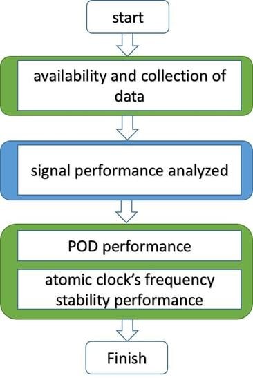
The paper is organized as follows. First, the availability and collection of data are described in Section 2. In Section 3, the signal performance is analyzed in detail. POD and the atomic clock’s frequency stability performance are presented in Section 4. The main conclusions are provided in the final section.

2. Data Availability and Collection

Owing to the promotion of International GNSS (Global Navigation Satellite System) Service (IGS) [20], the accuracy and reliability of GNSS products are improved significantly during the last two decades. The IGS network consists of more than 450 stations distributed around the world, and about 250 stations now track multi-GNSS satellites data, including GPS, GLONASS, Galileo, BDS, QZSS, IRNSS and SBAS. It should be noted that there are four frequencies of open service signals transmitted by BD3 satellites, namely, B1I, B1C, B2a and B3I, and, at present, more than 100 stations can record BD3 signals. However, affected by the firmware version, most of the receivers can only track B1I and B3I signals and even parts of those satellites. Until now, only three types of receivers that come from the IGS backbone network can track BD3 dual-frequency signals, which are made by JAVAD, Trimble and Septentrio.
The international GNSS Monitoring and Assessment Service (iGMAS) was developed by China [21] and a backbone network has been set up in the mainland of China and around the world. The network would consist of 30 stations, in which 24 stations have been constructed. Note that all these stations can receive the BD3 open service signals. Three types of receivers, manufactured by Chinese companies, that is, the 20th and 54th Institutes of the China Electronics Technology group Corporation (CETC) and Unicore Communications, Inc., are employed by these stations. 
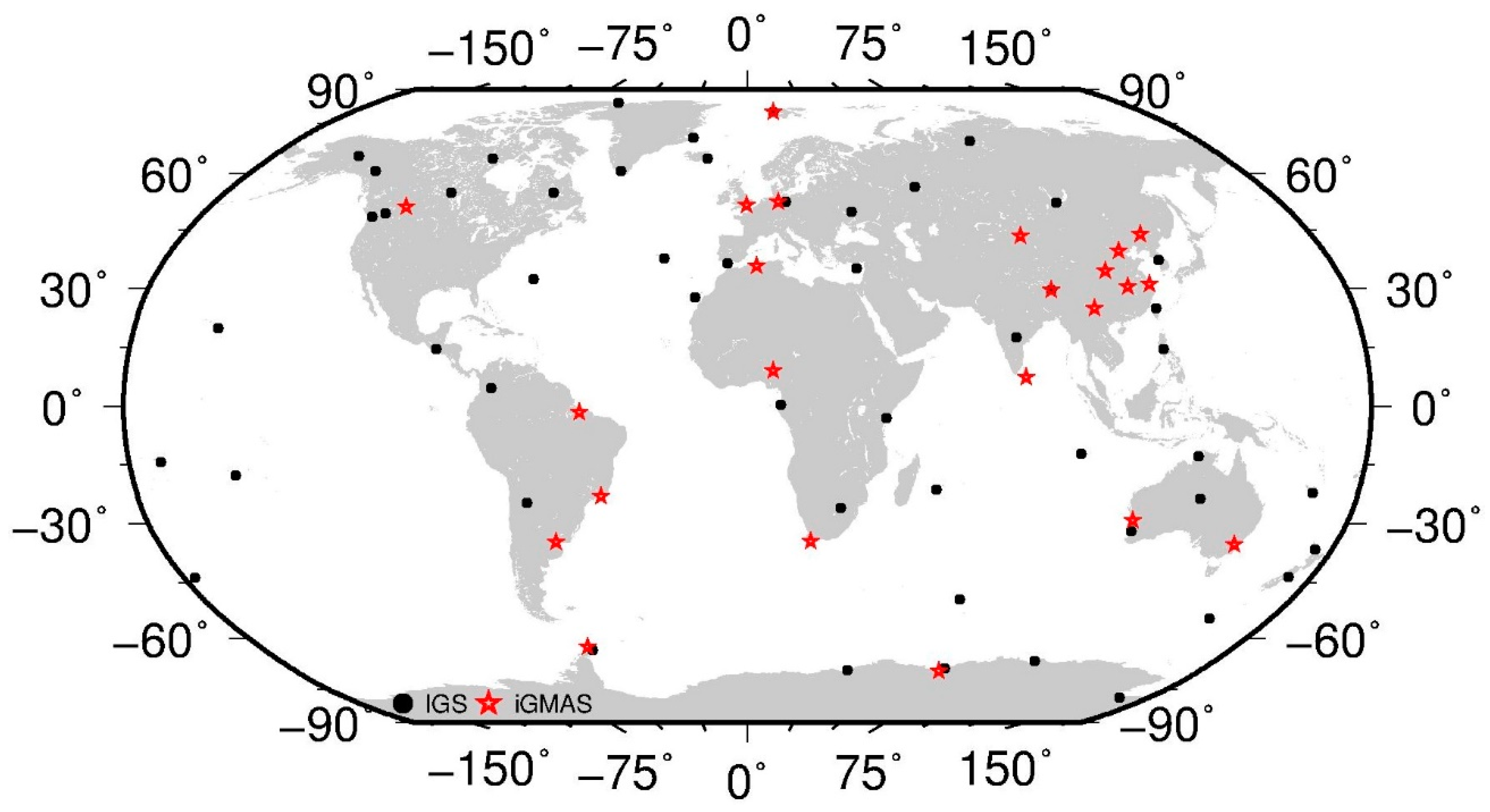
Table 1 lists the information about the capable receivers. The distribution of these stations that can track BD3 open service signals is shown in Figure 1. Given that only receivers from iGMAS can track all the BD3 open service signals, we evaluated the signal performance using the iGMAS receivers’ data in Section 3. In addition, considering the influence of station distribution on POD, the stations from IGS and iGMAS were used in the experiments presented in Section 4.

3. Signal Performance

3.1. Pseudorange Code Bias and Signal Noise

The pseudorange code bias in the BD2 satellites was first detected and verified by multipath (MP) combination, which was presented by Estey and Meertens and applied in the TEQC toolkit to edit GPS and GLONASS observation data [22]. This combination utilizes dual-frequency observation data. MP combination is GEO-free, which is not influenced by errors of satellites and site location, troposphere delay and first-order ionosphere delay. The original combination series only contained phase ambiguity, multipath and noise influence. The phase ambiguity can be eliminated by the arithmetic average. The multipath delay in phase, which is much smaller than pseudorange, can be ignored. Thus, MP combination can be used to evaluate the pseudorange code multipath and noise level. In general, the combination should be expressed as
M P i = P i f i 2 + f j 2 f i 2 f j 2 λ i φ i + 2 f j 2 f i 2 + f j 2 λ j φ j B i
where f represents the signal frequency, P and φ represent the pseudorange code and carrier phase observation, λ is the wavelength of the phase and B stands for the phase ambiguity bias, and the subscripts i and j represent the frequency of the combined signals.
In the study, we collected all the available data in the iGMAS network. The observation data of the BD3 open service signals at DOY 070 in 2019 was adopted for test and analysis. MP combination series versus elevation are presented in Figure 2.
In Figure 2, the B1I and B3I observation signals transmitted by BD2 MEO Satellites are presented together with the BD3 MEO FOC B1I, B1C, B2a and B3I signals. Seen from Figure 2, there is an obvious bias in the B1I and B3I signals transmitted by BD2 satellites, whilst the variation of the mean multipath does not distribute around zero. Moreover, an obvious tendency with elevation can be found from the positive value (low elevation) to negative values (high elevation). It is noteworthy that this pseudorange code bias has almost been eliminated in the BD3 MEO FOC satellites in the B1I, B1C, B2a and B3I signals. As a result, the MP combination variation is smooth when the elevation is high but fluctuates largely in low elevation, and the combination series is an almost zero mean distribution. According to our analysis, the Root Mean Square (RMS) of the BD3 MP combination is about 0.1 m when the elevation is in the vicinity of zenith. As shown in Figure 2, the data in “BD3-B1C” shows a slower convergence and it is more discrete than the other three BD3 frequencies. After comparing the four frequencies of open service signals, the noise level of the B1C signal is much larger than the other three frequencies’ observation data, which may indicate that the B1C signal is more sensitive to the multipath and noise.
Furthermore, we demonstrate the MP combination versus elevation and azimuth in the station local coordinate frame, where the orientation of the azimuth is toward the north and clockwise rotation. The MP combination series of BD2 and BD3 together with GPS and Galileo satellites are shown in Figure 3, where only B1I in BD2, B1C in BD3, L1 in GPS and E1 in Galileo are presented, and only the multipath combination data range between ± 2 meters is displayed. Seen from Figure 3, the MP combination series shows the symmetric distribution with the azimuth in the four satellites, and only the BD2 satellites present an elevation-dependent bias.
In addition, we estimated the Signal to Noise (S/N) data recorded by the iGMAS HMNS station at DOY 070, 2019. The site is located in Hermanus, South Africa, and the type of the receiver equipped on HMNS is “gnss_ggr”, which can track all the open service signals transmitted by the BD3 satellites. The S/N performance is displayed in Figure 4. As shown in the figure, the S/N values of all signals are weak at low elevations, but the S/N can be improved as the elevation increases. Besides, the S/N values reach a maximum when the elevation is larger than 60 deg.
As shown in Figure 4, for BD3 signals, the S/N of B1C is about 3 dBHz weaker than that of the other three signals and its S/N is about 35–37 dBHz at low elevation (10 deg), and 52 dBHz at high elevation (90 deg), while the S/N values of the other three signals are about 40–42 dBHz at low elevation (10 deg) and 55 dBHz at high elevation (90 deg). This may be caused by the signal constitution of the BD3 satellites. The structure of the B1C signal consists of two components, namely, the data branch and pilot branch, which is similar to the GPS L1C and Galileo E1OS. The navigation message was modulated on the data branch only, which can reduce the signal acquisition time and improve the accuracy of the weak signals [2]. The power distribution ratio of the data and the pilot branch is 1:3, which can improve the tracking threshold by 4.8 dB [23]. The designed minimum received power level on the ground is −159 dBW for B1C, which is 1.5 dB lower than that of the Galileo E1OS and GPS L1C signals. These designs may be the reason for the weak S/N and a slightly noisier signal performance for B1C.
Besides, compared with BD3 satellites, signal S/N values of Galileo E1 and GPS L1 are presented at the same level, but the B1I, B2a and B3I S/N values are obviously stronger than the Galileo and GPS S/N values. This may be related to the special configuration used by receivers, which may enhance the capability of the BDS signal tracking.

3.2. Phase and Pseudorange Code Evaluated by Precise Orbit Determination

The residuals of phase and pseudorange code have also been analyzed in precise orbit determination procedure. As the first order of the ionosphere delay can be eliminated by dual-frequency combination observation data, thus, a carrier phase and pseudorange code Ionosphere-free (IF) combination data are used in POD. The IF combination can be expressed as
I F = a R i + b R j { a = f i 2 f i 2 f j 2 b = f j 2 f i 2 f j 2
where IF represents the combined data of the IF carrier phase and pseudorange code, a and b are the combination coefficients, f and its subscripts are the same meanings as formula (1), and R is the range observation of phase or pseudorange.
Positioning And Navigation Data Analyst software (PANDA) [24], developed by Wuhan University, Wuhan, China, is used for the POD in the study, and the undifference algorithm is adopted in the software. Four open service signals are used and four kinds of IF combinations, (B1I, B2a), (B1I, B3I), (B1C, B2a), (B1C, B3I), are set up herein. The information about these combinations is listed in Table 2. The IF combination coefficients of the selected four situations are given in the table, and the noise level of the four kinds of IF combinations are calculated using the error spread rule. σ B 1 I , σ B 1 C , σ B 2 a and σ B 3 I in Table 2 are the standard deviation (STD) values of the B1I, B1C, B2a and B3I phase or pseudorange observation.
Considering that the iGMAS stations can track all the open service signals of BD3 satellites at present, only the iGMAS stations are used for the BD3 precise orbit determination in the paper. Observation data from DOY 030 to 059 2019 is utilized in the study and a 72-h arc length is adopted. Table 3 summarizes the observation models and force models used in our POD processing. In addition, the receiver and satellite clock offsets are also estimated together with the orbit determination process, and the white-noise constraint is used between adjacent epochs. Note that the coordinates of iGMAS stations are estimated with a tight constraint of about 5 cm, and the Earth Orientation Parameters (EOP) are fixed to the IERS EOP 14 C04 series. Besides, the above four types of IF combinations are used for the BD3 satellites POD.
The satellites antenna phase center offset (PCO) parameters supplied by the BeiDou Operational Control Center are used in the study. It should be noted that the space vehicle number (SVN) is absent in the BD3 FOC satellites and it is assigned and used within the IGS-MGEX project. The residuals of phase and pseudorange are presented in Figure 5, where the four types of IF combinations are displayed by different colors. According to the results, the B1I-B2a combination performs best in the IF pseudorange residuals, while B1C-B3I is the worst. The corresponding statistical results are listed in Table 4. In addition, the combination signal seems to be contaminated by B1C signal, which is consistent with the results acquired from the multipath combination. However, when it comes to the IF phase combination, the residual of B1C-B2a is the minimum and all four combinations are in the same magnitude, which is consistent with the noise level derived in Table 2.
In addition, a two-day overlap difference between two adjacent arcs was used to evaluate the orbit precision. RMS values of the BD3 satellites overlap difference are shown in Figure 6. Within the process of POD, only the BD3 satellites are calculated using the four types of IF combinations. The statistical RMS values of the overlap in the along-track, cross-track, radial and three dimensions (3D) are presented in the figure. Besides, the mean observation counts of the four IF combinations in each arc are also demonstrated on the dual-Y axis.
As Figure 6 shows, the IF combination of B1I-B3I performs best and its RMS values in the along-track, cross-track, radial and 3D directions are 14.4 cm, 8.7 cm, 3.9 cm and 20.0 cm, respectively, followed by B1C-B2a and B1I-B2a, whilst B1C-B3I shows the worst performance. Interestingly, these results are in the reverse order of the mean observation counts. The count of the observation used in the four types of IF combinations may be related to the capability of receivers. As the observation accuracy of phase is much higher than that of the pseudorange, the weights of the phase and pseudorange observation are generally set as 100:1. According to the residual data listed in Table 4, we suggest the IF combination of the B1C-B2a should be adopted first, which may enhance the precision of the parameters in the same situation. The results and mean observation count of the four IF combinations’ overlap are both listed in Table 5.

3.3. Inter-Frequency Phase Bias Evaluation

At present, four open service signals are available for the BD3 satellites and dual-frequency IF combinations are widely used in the precise orbit determination and clock bias estimation. In general, the IF combinations of signals can eliminate most of the ionosphere delay. Furthermore, the difference between the two IF combinations, namely, Geometry-Free Ionosphere-Free Phase (GFIFP) combination, is both geometry-free and ionosphere-free [30]. The GFIFP combination is expressed as
G F I F P ( i , j , k ) = I F ( i , j ) I F ( i , k ) = f i 2 ( f j 2 f k 3 ) ( f i 2 f j 2 ) ( f i 2 f k 2 ) R i f j 2 f i 2 f j 2 R j f k 2 f i 2 f k 2 R k
where f is the frequency of the signals, the subscripts i, j, k indicate the frequency index, and f i > f j > f k , R represents the phase observation (in meters).
The GFIFP combinations for the BD3 satellites as well as the GPS Block IIF and Galileo FOC satellites are presented in Figure 7. It is noteworthy that the observation units are unified in meters and the statistical data comes from the station KUN1 in the iGMAS network. As shown in Figure 7, the frequencies in the legends are presented referring to the Receiver INdependent Exchange (RINEX) definition version 3.04 [31], where 1/2/5/6 in BD3 stand for B1C/B1I/B2a/B3I, 1/2/5 in GPS represent L1/L2/L5 and 1/5/7 in Galileo stand for E1/E5a/E5b. Seen from Figure 7, the GFIFP combination distribution of C20 is not white-noise and is not located around zero. Its maximum variation reaches about ± 2 cm and the magnitude is almost the same as both the B1C/B2a/B3I and B1I/B2a/B3I combinations. It should be noted that B2I is transmitted only by the BD2 satellites. The GFIFP combination results of B1I, B2I and B3I have been presented in previous research [32], which have shown a similar performance as BD3. In addition, similar to the BD3 satellites, the series variation of the GPS Block IIF can reach ± 5 cm. It is noteworthy that the GFIFP combination of Galileo performs best and no obvious variation can be found.

4. POD and the Atomic Clock’s Frequency Stability Performance

In order to analyze the POD performance of the BD3 satellites, about 100 stations in the iGMAS and IGS backbone network are used, which can track BD3 as well as the GPS and Galileo satellites. The sites distribution is shown in Figure 1. Note that, the dual-frequency IF combination of B1I and B3I is employed and a 72-h arc length is adopted in batch processing. The “One-step” method is utilized in the study and the POD strategy is similar to the method listed in Table 3 using data from DOY 030 to 090.
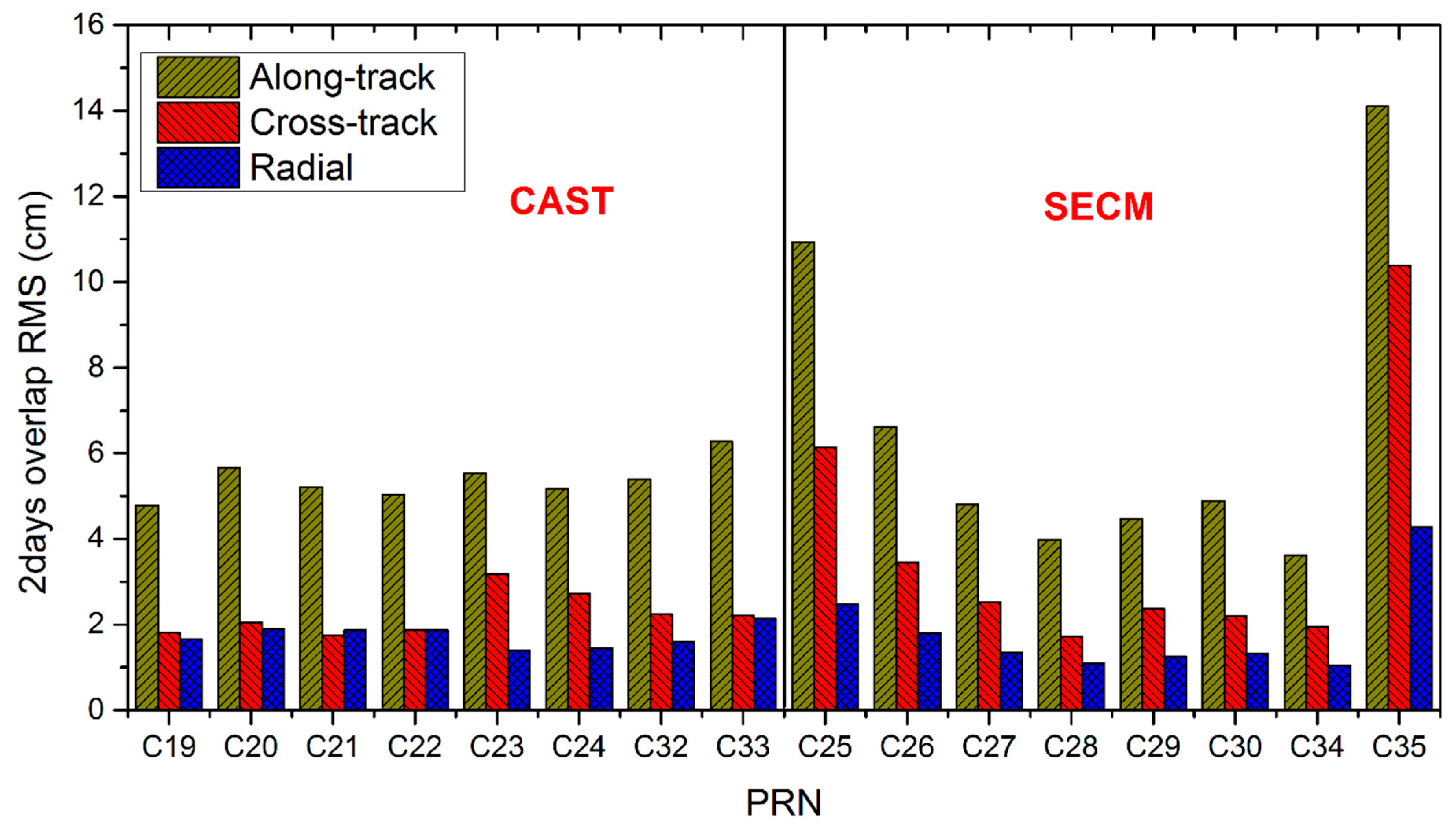
Figure 8 shows the RMS values of two-day overlap orbit in the along-track, cross-track and radial direction. As few stations can track PRN (Pseudo Random Noise code), C36 (M17), and C37 (M18) signals now, the statistical data only contains the sixteen BD3 MEO satellites. We divide these satellites into two categories according to the manufacturers, that is, C19/C20/C21/C22/C23/C24/C32/C33 made by CAST and the remaining satellites made by SECM.
Seen from Figure 8, the two-day overlap results are almost at the same magnitude, which are about 5.0 cm in the along-track, 2.2 cm in the cross-track, 1.5 cm in the radial and 5.7 cm in the 3D direction. Besides, the SECM satellites are a little better than the CAST satellites in overlapping accuracy. Among all the sixteen satellites, C25, C26 and C35 present the worse accuracies, compared with the other satellites. This may be related to the observation count used in POD processing. It should be noted that these three satellites were launched in the second half of 2018, later than other satellites. At present, only a few receivers can track these satellites due to the old firmware version of receivers. The detailed statistical results are listed in Table 6.
Satellite Laser Ranging (SLR) is an optical system and widely used in orbit determination and orbit validation, which can be regarded as an external measurement method to evaluate the range between satellites and laser stations. It is a two-way ranging instrument. In general, the laser is transmitted by the SLR stations and reflected by laser retroreflector array (LRA) which was installed on the satellite. Then, the range can be calculated through multiplying the time interval between laser transmitting and receiving by the vacuum speed of light. The ranging accuracy of SLR is better than 1 cm, which indicates that it is an effective measuring method for orbit validation. Considering that the maximum nadir angle measured by SLR is less than 15 deg, the main SLR residual of the orbit is the error in the radial direction.
Four satellites (C20, C21, C29 and C30) of the BD3 MEO satellites are tracked by the International Laser Ranging Service (ILRS) [33] and the LRA offsets (expressed in satellite coordinate system) from the satellite center of the mass used in the paper are listed in Table 7. The SLR residuals are shown in Figure 9.
Seen from Figure 9, the absolute values of residuals greater than 20 cm have been removed and only a few normal points are deleted. It should be noted that more than 98% of the original data are retained and used, as shown in the last three columns of Table 8. The corresponding statistical results are also listed in Table 8, including the mean, Standard Deviation (STD) and RMS values of the residual series. The RMS values of SLR validation series of C20/C21/C29/C30 are 5.1 cm, 6.4 cm, 4.7 cm, and 4.3 cm, and a tiny constant bias of about 2 4 cm can be found in the CAST satellites (C20, C21) and SECM satellites (C29, C30), while there is no systematic bias. Fortunately, the SLR validation accuracy is consistent with the results of the BD2 MEO satellites.
In addition, high-performance atomic clocks are very essential for satellite navigation and positioning systems. In general, clock bias can be estimated together with orbit parameters. The estimated clock bias parameters are the deviation from the system reference time, which are actually a kind of phase data. Different from the previous BD2 satellites, improved rubidium atomic frequency standard (RAFS) and the Passive Hydrogen Maser (PHM) made in China are installed on BD3 satellites. To evaluate the atomic clock frequency stability, Allan Deviation is an effective method, which can be expressed as:
σ ( τ ) = 1 2 ( N 2 ) τ 2 i = 1 N 2 [ x i + 2 m 2 x i + m + x i ] 2 , N = int ( N / m ) + 1
where τ represents the averaging time interval, N is the number of clock parameters within τ , x means the clock bias parameters.
To avoid the influence of gross errors, the trend term in the clock bias parameters is removed by quadratic linear fitting. The outliers greater than three times that of the STD are then marked and removed. In order to obtain more statistical samples, the overlapping Allan Deviation is adopted in the study and the corresponding results are presented in Figure 10.
As Figure 10 shows, the clock’s frequency stability of BD3 satellites improves obviously. This is mainly because the atomic clocks installed on BD2 satellites are the first generation RAFS made in China and the frequency accuracy and stability are relatively low. According to our analysis, the frequency stability of BD3 is approximately 2.43 × 10⁻¹⁴ at an interval of 10,000 s, and 2.51 × 10⁻¹⁵ at an interval of 86,400 s. Two distinctly sharp minima can be found in the vicinity of 86,400 s and 172,800 s, which is consistent with the orbital period. This indicates that the clock bias may be contaminated by orbit errors.
In Figure 10, the two auxiliary dotted lines, 1 / τ and 1 / τ , represent white noise and random walk noise, respectively [34]. The results about clock frequency stability of GPS, GLONASS, Galileo and BD2 satellites are also shown in the figure, and the experimental results indicate that the frequency stability of BD3 is a little better than that of the GPS Block IIF (RAFS) satellites, but worse than that of the Galileo FOC satellites (PHM). The performance of the BDS clock frequency stability at averaging time intervals of 10000 s and 86400 s is listed in Table 9.

5. Conclusions

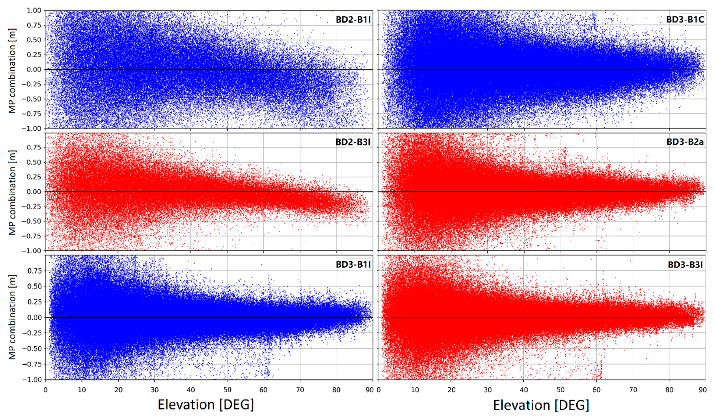
Global service of BDS has been provided since 27 Dec. 2018. At present, eighteen BD3 MEO FOC satellites have been launched into space, transmitting in four open service signals, namely B1I, B1C, B2a and B3I. In the study, we mainly focus on the signal characteristics of the BD3 open service signals. Pseudorange code noise level is estimated by multipath combination and the code bias founded in BD2 IGSO and MEO satellites are proven to be eliminated in the BD3 satellites. The multipath combinations show that the B1C pseudorange code is much noisier than the other three signals. In addition, the residuals of pseudorange and phase using four types of IF combinations with about 30-day data are evaluated by precise orbit determination. Fortunately, the pseudorange results are consistent with the multipath combination results. This may be related to the signal constitution and power distribution. The designed minimum received power levels on the ground is −159 dBW for B1C, which is 3 dB lower than that of the BDS B2a signal. According to our analysis, these designs may be the reason for the weak S/N and a slightly noisier signal performance of the B1C signal. The phase combination residuals of these four IF combinations are in the same magnitude and the residuals of B1I-B3I, B1C-B3I, B1I-B2a, B1C-B2a IF phase combinations are 5.9 mm, 5.2 mm, 4.9 mm and 4.8 mm, respectively. Considering the noise amplitude and compatibility with other GNSS, the B1C and B2a combination is recommended in priority. Inter-frequency phase bias of the BD3 satellites is also evaluated by GFIFP combination. The results show that obvious variation can be found in the GFIFP series and the amplitude is about 2 cm. Similar results are also found in the GPS BLOCK IIF satellites, but the amplitude of GPS is 5 cm. Besides, the GFIFP combination series of the Galileo is a zero mean distribution.
In addition, a multi-GNSS POD in the study is performed using about a hundred global-distributed IGS and iGMAS stations. Three-day arc length and B1I-B3I IF combination are used and the 48-h orbit overlap results show that the accuracies of the orbit are about 5.0 cm in the along-track, 2.2 cm in the cross-track, and 1.5 cm and 5.7 cm in the radial and 3D directions, respectively. Considering that the four satellites of BD3 can be tracked by ILRS, the RMS values of the SLR residuals for C20, C21, C29, and C30 are 5.1 cm, 6.4 cm, 4.7 cm and 4.3 cm respectively. The atomic clock’s frequency stability is evaluated as well, using the clock bias parameters calculated in POD. The results of overlapping Allan Deviations show that the frequency stability of BD3 is approximately 2.43 × 10⁻¹⁴ at an interval of 10,000 s and 2.51 × 10⁻¹⁵ at an interval of 86,400 s, which is a little better than that of the GPS BLOCK IIF satellites but worse than that of the Galileo FOC satellites.
According to the study above, compared with the BD2 satellites, the performance of the BD3 FOC in-orbit satellites has been significantly enhanced in the signal performance and atomic clock’s frequency stability. Thus, better performance can be expected with the full constellation operation by the end of 2020.

Author Contributions

X.X. and Q.Z. provided the initial idea of the study; X.X. performed the data analysis and wrote the article; X.W. helped with data organization and analysis; Q.Z and J.L. supervised the experiments.

Funding

This research was funded by National Natural Science Foundation of China (Grant Nos. 41574030, 41774035).

Acknowledgments

The authors are very grateful to IGS, iGMAS and ILRS for data supply.

Conflicts of Interest

The authors declare no conflict of interest.

References

  1. CSNO, BeiDou Navigation Satellite System Signal in Space Interface Control Document Open Service Signal B2a (Version 1.0). Available online: http://www.beidou.gov.cn/xt/gfxz/201712/P020171226742357364174.pdf. 2017 (accessed on 29 April 2019).
  2. CSNO, BeiDou Navigation Satellite System Signal in Space Interface Control Document Open Service Signal B1C (Version 1.0). Available online: http://www.beidou.gov.cn/xt/gfxz/201712/P020171226741342013031.pdf. 2017 (accessed on 29 April 2019).
  3. CSNO, BeiDou Navigation Satellite System Signal in Space Interface Control Document Open Service Signal B1I (Version 3.0). Available online: http://www.beidou.gov.cn/xt/gfxz/201902/P020190227593621142475.pdf. 2019 (accessed on 29 April 2019).
  4. CSNO, BeiDou Navigation Satellite System Signal in Space Interface Control Document Open Service Signal B3I (Version 1.0). Available online: http://www.beidou.gov.cn/xt/gfxz/201802/P020180209623601401189.pdf. 2018 (accessed on 29 April 2019).
  5. Wu, M.; Liu, W.; Lu, C.; Zhang, X.; Li, X.; Yu, S.; Wickert, J. Initial assessment of the COMPASS/BeiDou-3: New-generation navigation signals. J. Geod. 2017, 11, 21–1240. [Google Scholar]
  6. Montenbruck, O.; Hauschild, A.; Steigenberger, P.; Hugentobler, U.; Teunissen, P.; Nakamura, S. Initial assessment of the COMPASS/BeiDou-2 regional navigation satellite system. GPS Solut. 2012, 17, 211–222. [Google Scholar] [CrossRef]
  7. Li, M.; Qu, L.; Zhao, Q.; Guo, J.; Su, X.; Li, X. Precise Point Positioning with the BeiDou Navigation Satellite System. Sensors 2014, 14, 927–943. [Google Scholar] [CrossRef] [PubMed] [Green Version]
  8. Li, X.; Ge, M.; Dai, X.; Ren, X.; Fritsche, M.; Wickert, J.; Schuh, H. Accuracy and reliability of multi-GNSS real-time precise positioning: GPS, GLONASS, BeiDou, and Galileo. J. Geod. 2015, 89, 607–635. [Google Scholar] [CrossRef]
  9. Guo, J.; Xu, X.L.; Zhao, Q.L.; Liu, J.N. Precise orbit determination for quad-constellation satellites at Wuhan University: Strategy, result validation, and comparison. J. Geod. 2016, 90, 143–159. [Google Scholar] [CrossRef]
  10. Zhao, Q.; Guo, J.; Li, M.; Qu, L.; Hu, Z.; Shi, C.; Liu, J. Initial results of precise orbit and clock determination for COMPASS navigation satellite system. J. Geod. 2013, 87, 475–486. [Google Scholar] [CrossRef]
  11. Prange, L.; Orliac, E.; Dach, R.; Arnold, D.; Beutler, G.; Schaer, S.; Jäggi, A. CODE’s five-system orbit and clock solution—The challenges of multi-GNSS data analysis. J. Geod. 2017, 91, 345–360. [Google Scholar] [CrossRef]
  12. Chen, X.; Ge, M.; Marques, H.A.; Schuh, H. Evaluating the impact of higher-order ionospheric corrections on multi-GNSS ultra-rapid orbit determination. J. Geod. 2019. [Google Scholar] [CrossRef]
  13. Hauschild, A.; Montenbruck, O.; Sleewaegen, J.M.; Huisman, L.; Teunissen, P.J.G. Characterization of Compass M-1 signals. GPS Solut. 2012, 16, 117–126. [Google Scholar] [CrossRef]
  14. Shi, C.; Zhao, Q.; Hu, Z.; Liu, J. Precise relative positioning using real tracking data from COMPASS GEO and IGSO satellites. GPS Solut. 2012, 17, 103–119. [Google Scholar] [CrossRef]
  15. Lou, Y.; Gong, X.; Gu, S.; Zheng, F.; Feng, Y. Assessment of code bias variations of BDS triple-frequency signals and their impacts on ambiguity resolution for long baselines. GPS Solut. 2016, 21, 177–186. [Google Scholar] [CrossRef]
  16. Wanninger, L.; Beer, S. BeiDou satellite-induced code pseudorange variations: Diagnosis and therapy. GPS Solut. 2014, 19, 639–648. [Google Scholar] [CrossRef]
  17. Jiang, K.; Li, M.; Zhao, Q.; Li, W.; Guo, X. BeiDou Geostationary Satellite Code Bias Modeling Using Fengyun-3C Onboard Measurements. Sensors 2017, 17, 2460. [Google Scholar] [CrossRef]
  18. Zhou, R.; Hu, Z.; Zhao, Q.; Li, P.; Wang, W.; He, C.; Cai, C.; Pan, Z. Elevation-dependent pseudorange variation characteristics analysis for the new-generation BeiDou satellite navigation system. GPS Solut. 2018, 22, 60. [Google Scholar] [CrossRef]
  19. Wu, Z.; Zhou, S.; Hu, X.; Liu, L.; Shuai, T.; Xie, Y.; Tang, C.; Pan, J.; Zhu, L.; Chang, Z. Performance of the BDS3 experimental satellite passive hydrogen maser. GPS Solut. 2018, 22, 43. [Google Scholar] [CrossRef]
  20. Dow, J.M.; Neilan, R.E.; Rizos, C. The International GNSS Service in a changing landscape of Global Navigation Satellite Systems. J. Geod. 2009, 83, 689. [Google Scholar] [CrossRef]
  21. Jiao, W. International GNSS Monitoring and Assessment System (iGMAS) and Latest Progress; China Satellite Navigation Conference (CSNC): Nanjing, China, 21–23 May 2014. [Google Scholar]
  22. Estey, L.H.; Meertens, C.M. TEQC: The Multi-Purpose Toolkit for GPS/GLONASS Data. GPS Solut. 1999, 3, 42–49. [Google Scholar] [CrossRef]
  23. Betz, J.W.; Blanco, M.A.; Cahn, C.R.; Dafesh, P.A. Description of the L1C signal. In Institute Of Navigation (ION) GNSS; USGS: Fort Worth, TX, USA, 2006; Volume 4, pp. 2080–2091. [Google Scholar]
  24. Liu, J.; Ge, M. PANDA software and its preliminary result of positioning and orbit determination. Wuhan Univ. J. Nat. Sci. 2003, 8, 603–609. [Google Scholar]
  25. Wang, C.; Guo, J.; Zhao, Q.; Liu, J. Yaw attitude modeling for BeiDou I06 and BeiDou-3 satellites. GPS Solut. 2018, 22, 117. [Google Scholar] [CrossRef]
  26. Standish, E.M. “JPL Planetary and Lunar Ephemerides,” DE405/LE405. Interoffice memorandum: JPL IOM 312. F—98-048, 1998, August 26. Int. J. Astron. Astrophys. 2012, 2, 129–155. [Google Scholar] [CrossRef]
  27. Saastamoinen, J. Contributions to the theory of atmospheric refraction. Bull. Géodésique 1973, 107, 13–34. [Google Scholar] [CrossRef]
  28. Böhm, J.; Niell, A.; Tregoning, P.; Schuh, H. Global Mapping Function (GMF): A new empirical mapping function based on numerical weather model data. Geophys. Res. Lett. 2006, 33, L07304. [Google Scholar] [CrossRef]
  29. Guo, J.; Zhao, Q.; Geng, T.; Su, X.; Liu, J. Precise Orbit Determination for COMPASS IGSO Satellites During Yaw Maneuvers. In Proceedings of the Theory and Applications of Applied Electromagnetics; Springer Science and Business Media LLC: Berlin/Heidelberg, Germany, 2013; Volume 245, pp. 41–53. [Google Scholar]
  30. Montenbruck, O.; Hugentobler, U.; Dach, R.; Steigenberger, P.; Hauschild, A. Apparent clock variations of the Block IIF-1 (SVN62) GPS satellite. GPS Solut. 2012, 16, 303–313. [Google Scholar] [CrossRef]
  31. IGS, The Receiver Independent Exchange Format Version 3.04. 2018. Available online: https://kb.igs.org/hc/en-us/articles/201096516-IGS-Formats (accessed on 29 April 2019).
  32. Wang, G. On the Analysis of BeiDou Observations’ Characteristics and Its Application in PPP Integer Ambiguity Resolution. Ph.D. Thesis, GNSS Research Center, Wuhan University, Wuhan, China, 2016. (In Chinese with English Abstract). [Google Scholar]
  33. Pearlman, M.; Degnan, J.; Bosworth, J. The International Laser Ranging Service. Adv. Space Res. 2002, 30, 135–143. [Google Scholar] [CrossRef]
  34. Senior, K.L.; Ray, J.R.; Beard, R.L. Characterization of periodic variations in the GPS satellite clocks. GPS Solut. 2008, 12, 211–225. [Google Scholar] [CrossRef]
Figure 1. The distribution of stations from the International GNSS Service (IGS) and international GNSS Monitoring and Assessment Service (iGMAS) backbone network which can track the BD3 open service signals. The block dots represent the IGS stations and the red stars represent the iGMAS stations.
Remotesensing 11 01559 g001
Figure 2. The BD2 and BD3 medium Earth orbit (MEO) satellites’ multipath combination versus elevation.
Remotesensing 11 01559 g002
Figure 3. The BD2 (a), BD3 MEO satellites (b) together with the Global Positioning System (GPS) (c) and Galileo satellites (d) multipath combination versus elevation and azimuth (units: meter).
Remotesensing 11 01559 g003
Figure 4. The signal to noise (S/N) performance of the observation data recorded by the HMNS station, where the S/N values of BD3 B1I/B1C/B2a/B3I signal are shown in the left, Galileo E1/E5a/E5b and GPS L1/L2/L5 signal performance are shown in the middle and right panel, respectively.
Remotesensing 11 01559 g004
Figure 5. The phase and pseudorange ionosphere-free (IF) combination residuals as a function of epoch.
Remotesensing 11 01559 g005
Figure 6. The root mean square (RMS) values of the two-day overlap in orbit determination using B1CB2a, B1CB3I, B1IB2a and B1IB3I in the along-track, cross-track, radial and 3D directions. The mean observation counts of four IF combinations in each arc are presented on the dual-Y axis.
Remotesensing 11 01559 g006
Figure 7. The geometry-free ionosphere-free phase (GFIFP) combinations as a function of the epoch for the BD3 C20 satellite (B1C/B2a/B3I and B1I/B2a/B3I) as well as the GPS G06 and Galileo E01 satellites. The legends 1/2/5/6 in satellite C20 stand for B1C/B1I/B2a/B3I respectively, and 1/2/5 in G06 represent L1/L2/L5, and 1/5/7 in E01 stand for E1/E5a/E5b, respectively.
Remotesensing 11 01559 g007
Figure 8. The RMS values of the BD3 MEO satellites’ two-day (2days) overlap comparison in the along-track, cross-track and radial directions. The left panel presents the results of the satellites made by CAST and the right panel is the results of satellites made by SECM.
Remotesensing 11 01559 g008
Figure 9. The satellite laser ranging (SLR) validation residuals of the BD3 MEO satellites, where C20/C21 are made by CAST and C29/C30 are made by SECM.
Remotesensing 11 01559 g009
Figure 10. The GPS/GLONASS/Galileo/BDS satellites frequency stability calculated by overlapping Allan Deviation.
Remotesensing 11 01559 g010
Table 1. Information about the third generation of BeiDou (BD3) satellites capable receivers.
Receiver TypeFirmware VersionManufacturerTracking FrequencyAgency
JAVAD TRE_3 DELTA3.7.2JAVADB1I/B3IIGS
TRIMBLE NETR95.3.7TrimbleB1I/B2a/B3IIGS
SEPT POLARRX55.2.0SeptentrioB1I/B3IIGS
CETC-54-GMR-4016SW-Version1.0CETC-54B1I/B1C/B2a/B3IiGMAS
gnss_ggr1.0CETC-20B1I/B1C/B2a/B3IiGMAS
UNICORE UB4B0I20100UnicoreB1I/B1C/B2a/B3IiGMAS
Table 2. The information about the open service signals and four types of ionosphere-free (IF) combinations.
SignalFrequency (MHZ)Combination TypeCombination CoefficientNoise Level
ab
B1C1,575,420B1I-B3I2.9437−1.9437 8.67 σ B 1 I 2 + 3.78 σ B 3 I 2
B1I1,561,098B1C-B3I2.8436−1.8436 8.09 σ B 1 C 2 + 3.40 σ B 3 I 2
B2a1,176,450B1I-B2a2.3144−1.3144 5.36 σ B 1 I 2 + 1.73 σ B 2 a 2
B3I1,268,520B1C-B2a2.2606−1.2606 5.11 σ B 1 C 2 + 1.59 σ B 2 a 2
Table 3. The observation models and force models used in precise orbit determination (POD).
ItemModel
Observation combination Undifferenced IF of code and phase, B1I-B3I, B1C-B3I, B1I-B2a, B1C-B2a
Sampling interval300 s
Cutoff elevation7 deg
Arc length 72 h
Satellites antenna phase center supplied by BeiDou Operational Control Center
GeopotentialEGM 2008, 12 × 12 degree
Attitude model Continuous yaw-steering model [25].
N-body gravitation Sun, Moon, Mercury, Venus, Mars, Jupiter Saturn, Uranus, Neptune and Pluto, JPL DE405 ephemeris are used [26]
Earth Orientation ParametersFixed to IERS EOP 14 C04 dataset
Tropospheric delay The Saastamoinen model for the initial dry and wet zenith delay [27], projection function GMF is used [28], and the wet delay was estimated as constant every 2 h.
Solar radiationECOM five-parameters model with a constant acceleration bias in the along-track direction [29].
Table 4. The root mean square (RMS) of B1I-B3I, B1C-B3I, B1I-B2a, B1C-B2a IF combination residuals in phase and pseudorange (units: mm).
B1I-B3IB1C-B3IB1I-B2aB1C-B2a
LC5.95.24.94.8
PC631820469720
Table 5. The results of the overlap comparison of the BD3 two-day overlap in the along-track, cross-track, radial and 3D directions (units: mm). The mean observation counts used in each arc are listed in the last column.
Along-trackCross-trackRadial3DObs. Count
B1C-B2a15794402001,643,662
B1C-B3I226148602951,436,591
B1I-B2a192110472411,496,300
B1I-B3I14487391841,731,146
Table 6. The results of the two-day overlap comparison of BD3 medium Earth orbit (MEO) satellites in the along-track, cross-track, radial and 3D directions (units: cm).
Satellite Manufacturer PRNAlong-trackCross-trackRadial3D
CASTC194.81.81.75.4
C205.72.01.96.3
C215.21.71.95.8
C225.01.91.95.7
C235.53.21.46.5
C245.22.71.46.0
C325.42.21.66.1
C336.32.22.17.0
SECMC2510.96.12.512.8
C266.63.51.87.7
C274.82.51.35.6
C284.01.71.14.5
C294.52.41.35.2
C304.92.21.35.5
C343.61.91.14.2
C3514.110.44.318.0
Table 7. The BD3 MEO laser retroreflector array (LRA) offset reference to the center of the satellite mass (units: m)
SVNPRNLRA Offset Reference to the Center of Satellite Mass
XYZ
C202C200.6021–0.07681.2367
C206C210.5986–0.08661.2650
C207C290.66460.42490.6427
C208C300.66460.42490.6427
Table 8. The satellite laser ranging (SLR) validation accuracy (MEAN, STD, RMS) of the BD3 MEO satellite’s orbit (units: cm).
PRNMEANSTDRMSNP#NP(U)Utilization%
C200.965.035.1292792499.7
C214.084.966.4295494398.9
C29−0.834.574.651034102098.7
C30−2.033.824.3296495198.7
Table 9. The frequency stability of the BD3 satellites at intervals of 10,000 s and 86,400 s.
PRNClockIntervalPRNClockInterval
10,000 s86,400 s10,000 s86,400 s
C01RAFS9.46 × 10−148.01 × 10⁻¹⁵C19RAFS2.98 × 10−143.28 × 10⁻¹⁵
C02RAFS1.05 × 10−138.82 × 10⁻¹⁵C20RAFS2.93 × 10−142.70 × 10⁻¹⁵
C03RAFS9.47 × 10−147.97 × 10⁻¹⁵C21RAFS2.84 × 10−142.95 × 10⁻¹⁵
C04RAFS8.45 × 10−147.52 × 10⁻¹⁵C22RAFS3.00 × 10−142.98 × 10⁻¹⁵
C05RAFS6.67 × 10−143.24 × 10⁻¹⁵C23RAFS1.82 × 10−142.22 × 10⁻¹⁵
C06RAFS9.60 × 10−141.13 × 10⁻¹⁴C24RAFS1.99 × 10−142.48 × 10⁻¹⁵
C07RAFS1.06 × 10−139.09 × 10⁻¹⁵C25PHM4.24 × 10−145.62 × 10⁻¹⁵
C08RAFS8.25 × 10−141.13 × 10⁻¹⁴C26PHM3.39 × 10−144.93 × 10⁻¹⁵
C09RAFS6.83 × 10−146.87 × 10⁻¹⁵C27PHM2.30 × 10−142.38 × 10⁻¹⁵
C10RAFS1.05 × 10−131.17 × 10⁻¹⁴C28PHM1.91 × 10−141.76 × 10⁻¹⁵
C11RAFS5.72 × 10−146.22 × 10⁻¹⁵C29PHM2.46 × 10−142.49 × 10⁻¹⁵
C12RAFS3.68 × 10−144.04 × 10⁻¹⁵C30PHM2.46 × 10−142.59 × 10⁻¹⁵
C13RAFS8.73 × 10−141.08 × 10⁻¹⁴C33RAFS2.45 × 10−142.41 × 10⁻¹⁵
C14RAFS3.31 × 10−143.94 × 10⁻¹⁵C35PHM6.32 × 10−133.84 × 10⁻¹⁴
C16RAFS3.55 × 10−142.64 × 10⁻¹⁵C36RAFS7.62 × 10−131.58 × 10⁻¹⁴

