1. Introduction
The share of renewable energy in power systems is increasing with the growing concern for environmental problems [
1]. The increase in renewable energy is making the operation of power systems more difficult due to the variability of renewable energy that changes power generation according to changes in nature [
2]. Furthermore, if the proportion of renewable energy is too high, it may cause instability in power systems. Therefore, a system is needed to improve the acceptability of renewable energy and to promote the stable operation of power systems in connection with renewable energy [
3,
4].
In the Republic of Korea, a new regime was launched in 2017, and a policy was announced to increase the proportion of renewable energy production in the Republic of Korea to 20% by 2030 [
5]. The Republic of Korea’s renewable energy generation ratio was 6.61% in 2015 [
6], and the number of new renewable energy sources is expected to increase rapidly by 2030. For the renewable energy source to be disseminated smoothly to the power system, it is necessary to supply equipment such as energy storage devices and flexible AC transmission systems (FACTS). However, investment in facilities is difficult worldwide due to the social atmosphere and economic factors. In this situation, the improvement of power system operation technology can be the cheapest and most efficient way to improve renewable energy supply [
7].
Many studies have been conducted to improve the acceptability of renewable energy in power systems until now [
8,
9], but studies focusing on voltage and reactive power have been insufficient compared to studies focusing on active power and frequencies [
10]. The reason for this is that voltage and reactive power have local characteristics compared to active power, and it is more difficult to identify its effects [
11]. Furthermore, there is a lack of interest in reactive power compared to active power due to economic factors in the power market [
12]. However, voltage and reactive power are essential factors to be considered to achieve the stable operation of renewable energy in power systems [
13,
14]. Reactive power sources can quickly respond to the variability of reactive power of renewable energy [
15].
The thermal and hydroelectric power generators in a power system are the source of dynamic reserve reactive power, which has a rapid response characteristic essential for maintaining the system’s voltage [
16]. Therefore, it is important to keep some reserves to respond adequately to possible system disturbances [
17]. Generators operate to match the generator output voltage with the scheduled voltage, such that when the generator voltage drops, the reactive power reserve falls as its output increases [
18,
19]. If a static load occurs, the system can prepare for its disturbance by securing the reactive power reserve by controlling the generator voltage in advance with facilities such as an on-load tap charger (OLTC) [
20].
Thus, this study proposes a method that secures the target reserves by controlling the generator output voltage by using the OLTC [
21]. Conventional OLTCs have been used sparingly due to the difficulties in calculating the local characteristics and influence of voltage and reactive power. In many countries, the OLTC is operating to control only the voltage of the bus connected to the transformer. However, as the use of electric power facilities becomes more important due to the recent rapid increase in electric power consumption worldwide, research on the efficient use of OLTC is being actively carried out [
22,
23,
24,
25]. Previous studies have focused on the voltage control function of the OLTC. Dynamic coordinated control of OLTC to SVC, STATCOM, and reactive power compensators have been studied extensively.
On the other hand, the difference from the previous research and this paper is that this paper proposes a method to secure the generator reactive power reserves that have a faster dynamic response characteristic than OLTC using optimal control of OLTC in steady-state. In the proposed method, tap reactive power and voltage sensitivity were analyzed and used to secure the generator reactive power reserve along with rapid and precise generator output-voltage control.
The composition of this paper is as follows.
Section 2 describes the voltage and reactive power sensitivity equations for securing the required reactive power reserve.
Section 3 formulates optimization problems based on the voltage and reactive power sensitivities and proposes an algorithm that can be applied in an online real-time environment to increase the penetration of renewable energy. Finally,
Section 4 is devoted to the conclusions.
2. Sensitivity Analysis for Optimal Tap Control
The voltage sensitivity following the tap adjustment can be defined with the change in the voltage level when the tap ratio has changed [
26]. Accordingly, the voltage sensitivity can be expressed as
Likewise, the reactive power sensitivity following the tap adjustment can be defined with the change of reactive power when the tap ratio has changed. The reactive power sensitivity can be expressed as
Equation (1) can be expanded into the equations that define the changes in active power (P) and reactive power (Q) at both ends of the transformer following the tap adjustment and then the change in V of the i-th bus based on the changes made in P and Q by applying the chain rule.
The voltage sensitivities ∂V/∂P and ∂V/∂Q consequential to the changes in P and Q can be estimated from the inverse matrix of a Jacobian matrix (cf. Newton–Raphson method) as follows.
The Jacobian inverse matrix is classified into four square matrices and the voltage change for the active power change corresponds to the lower left area and the voltage change for the reactive power change corresponds to the lower right area.
In order to develop Equation (3), the P and Q variations according to the tap change can be obtained as Equations (7) and (8). ∂P/∂t and ∂Q/∂t can be re-expanded by the equations that were defined as the change of conductance (G) and susceptance (B) following the tap adjustment. If the transformer tap connects the k-th bus and the l-th bus, the Equations (7) and (8) for the P and Q variations of k-th bus can be expressed as
In Equation (8), is the reactive power sensitivity, and an i-th diagonal element of the inverse Jacobian matrix. Based on the sensitivity value calculated in (8), the generator reactive power reserve can be adjusted by controlling OLTCs.
The equation below represents the power equation where conductance G and susceptance B were applied to calculate the power variation sensitivity against the Y-variation of admittance.
By applying the above equation to (6), each component can be calculated as
Next, the variation sensitivities of G and B following the tap adjustment can be calculated by performing a partial differentiation for the Y-variation equation based on the transformer tap ratio. The Y-variation equation following tap ratio adjustment (k-bus of the k-l transformer) is
is the admittance before tap ratio adjustment. The equations for the variations of G and B after dividing Y by G and B elements are
3. An Approach to Improve the Penetration of Sustainable Energy Using Optimal Transformer Tap Control
In this paper, the optimization problem has been constructed to obtain the optimal solution to improve the renewable energy penetration in terms of the voltage. The optimization problem can be developed with the voltage and reactive power sensitivity equations introduced earlier. The optimization problem is divided into two steps to reduce the number of iterations and improve the convergence.
First, this section introduces the optimization problem to adjust the generator operating voltages to the scheduled voltages. In the case where the generator reactive power reserve remains, the generator bus is operated with the specified active power output (P) and voltage (V), and is calculated as the PV bus in the power flow calculation. On the other hand, if there is no generator reactive power reserve, the generator bus voltage cannot be matched to the scheduled voltage. Therefore, the generator bus is operated with the specified active power output (P) and reactive power output (Q), and is calculated as the PQ bus in the power flow calculation. The first optimization problem is to adapt the operating voltages of the generators to the schedule voltages to convert the PQ buses to the PV buses. The reason for converting the generator PQ bus to the PV bus is that the reactive power sensitivity values derived from the nonlinear equation when the generator bus is the PQ bus is different from those of the PV bus. Then, the optimization problem for securing the reactive power reserve of the generator is solved. It is possible to control the fluctuation of the voltage and the reactive power of the renewable energy by securing the reactive power reserve of the generators.
3.1. Optimal Tap Control to Secure the Scheduled Voltage of Generators
First, when the reactive power output of the generator is at its maximum, the generator bus is calculated like the PQ bus. Therefore, the operation voltage of the generator is lower than the scheduled voltage. In this case, the optimization problem is constructed as shown in Equations (15)–(18), and the operating voltage of the generator bus is adjusted to the scheduled voltage by the transformer optimum operation.
1. Objective function
The objective function consists of the sum of the squares of the transformer control action. Excessive OLTC operation is inadequate because tap-changes can cause transients and mechanical failures [
23]. Therefore, the minimum transformer-tap control action is performed to adjust the voltage of generators to the scheduled voltage. In addition, the objective function, which is made up of the square of the transformer tap control action, allows the taps of the various transformers to operate properly, so that the transformer-tap operating margin is afforded.
represents the tap operation change in the
k-th transformer.
gives the weight of each transformer to set the change cost of each transformer differently.
represents the total number of transformers participating in the control.
2. Constraints
The constraint of the optimization problem is that the operating voltage of the generator operating on the PQ bus is set to the scheduled voltage, and the voltage of each bus is configured to fall within the operating voltage range. In the constraint condition, the voltage change due to the tap operation is calculated using the voltage change sensitivity for the tap operation. The configuration of the optimization formula using the voltage sensitivity allows a deterministic algorithm to find the optimal solution quickly. and represent the minimum and maximum limits of the i-th bus voltage, respectively, and represents the operating voltage of the j-th generator. and are the voltage values of the i-th bus and the j-th generator at initial state, respectively, obtained through power flow calculation. n is the total number of the voltage control buses, and m is the number of the generators participating in the voltage control. and represent the minimum and maximum limits of the k-th tap. and are the current tap position and tap change steps at initial state. The limit of the tap may be set to the facility rating, or may be set by the operator considering the operating margin of the tab.
3.2. Optimal Tap Control to Secure the Reactive Power Reserve of Generators
The generator voltage is secured by using Equations (15)–(18) and then the optimization problem is solved for securing the generator reactive power reserve. The configuration of Equations (19)–(22) is similar to that of Equations (15)–(18), but there are differences in the constraint conditions.
1. Objective function
In Equation (19), the objective function in the optimization problem is configured to find the minimum work values of the tap. Equation (19) is constructed as Equation (15) and avoids transients and mechanical failures with optimum control of the transformer taps.
2. Constraints
The constraints are the voltages of the buses and the reactive power reserves of the generators. The optimal control action can be taken after the optimization problem has been solved. The generator dynamic reactive power reserve that is required to respond to the variability of renewable energy can be secured by performing the optimal control action. The amount of the dynamic reactive power reserve required to improve the penetration of renewable energy in power systems varies with the system characteristics. Therefore, the reactive power reserve constraints can be set as the values simulated by system operators through dynamic simulation.
is the voltage values of the
i-th bus at the state after performing
Section 3.1.
and
represent the current reactive power reserve and minimum reactive power reserve limit of the
j-th bus.
n is the total number of the voltage control buses, and
m is the number of the generators participating in the voltage control.
and
are the current tap position and tap change steps at the state after performing
Section 3.1.
3.3. Proposed Approach to Improve the Penetration of Sustainable Energy
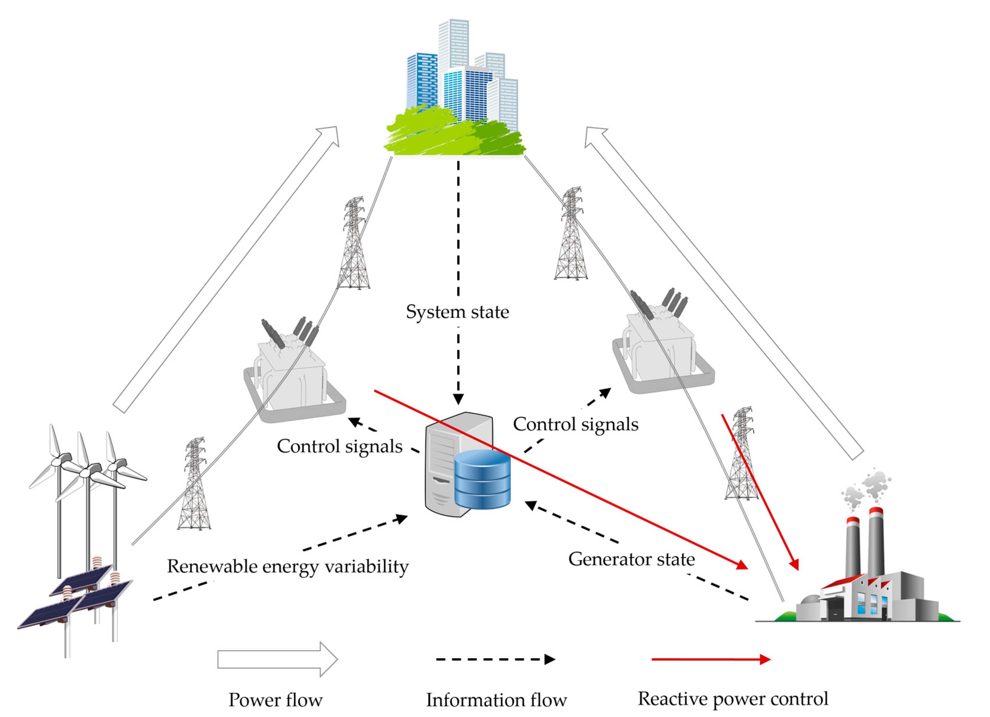
Figure 1 shows the proposed system to improve the penetration of renewable energy using the optimal transformer tap control in this paper. The system solves optimization problems to control the variability of renewable energy based on the load and power information received from the Energy Management System (EMS), as shown in
Figure 1. Then, the control signal based on the solutions of the optimization problem is transmitted to each OLTC by the power information transmission technique [
27,
28,
29,
30,
31]. The system configuration changes depending on the operation of the OLTCs, and as a result, the reactive power output amount of each generator is changed.
EMS used by Korea power system operators acquires and calculates the power system data every 2 s in steady-state. Therefore, in the proposed system is used in Korea, the system has to calculate the optimal control action within 2 s to receive next EMS snapshot data. In this paper, we construct a deterministic optimization problem using linear sensitivity analysis to enable fast computation. If faster computation is required or a power system size is too large to quickly compute, the computation time can be reduced by dividing the voltage control area based on the local characteristics of the voltage and performing parallel computing for each voltage control area [
32,
33].
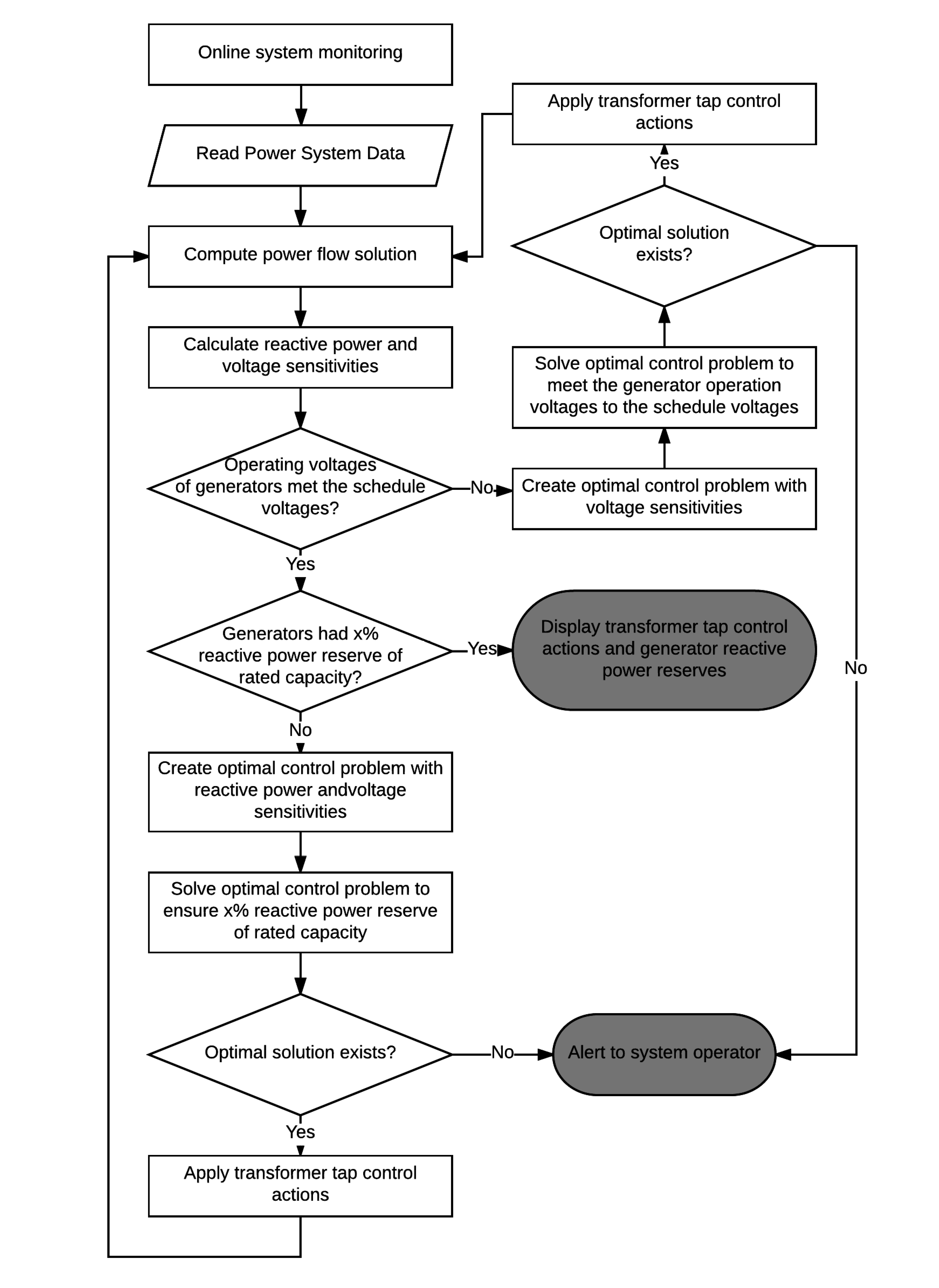
Figure 2 shows the flowchart of the algorithm for the method proposed in this paper. When the power system information is input first, the power flow is calculated based on this information to estimate the unknown values of the power system. Then, the sensitivities between the transformer and power system buses are calculated through a sensitivity analysis based on the values obtained from the power flow calculation. If the generator operating voltage is lower than the schedule voltage, the algorithm finds the optimal solution to match the generator voltage to the schedule voltage. The optimization problem is constructed based on the voltage and reactive power sensitivities obtained above. If the generator operating voltages are operating normally, it is checked whether the generator reactive power reserves are secured. If the reactive power reserve is less than the constraint, the optimal solution is found using the voltage and reactive power sensitivities and the optimum operation for securing the dynamic reactive power reserve is determined.
4. Case Study
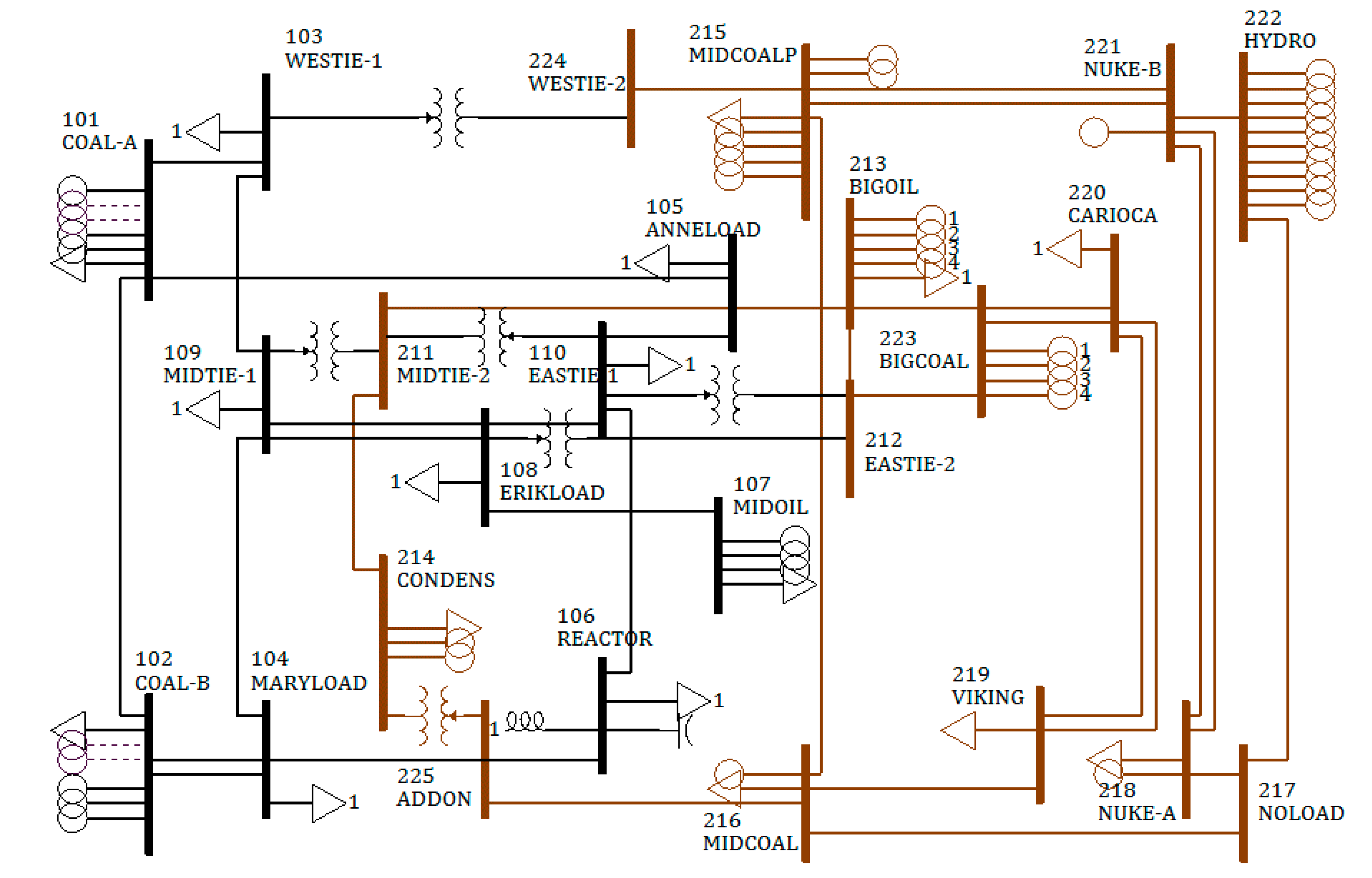
Simulations were performed for an IEEE 25-bus test system to conduct as a case study for the proposed method in this research. The network configuration of IEEE 25-bus test system is as seen in
Figure 3. To simulate the increased penetration of renewable energy according to the acquisition of the generator reactive power reserve, five renewable energy sources were connected to the No. 215 bus that had the lowest reactive power reserve. Each renewable energy source was set to have a capacity of 12 MW, 4 MVAr.
In
Figure 3, IEEE 25-bus test system has the 25 buses, and 11 buses are the generator buses. 17 buses have the loads, and the total amount of the loads is 3528 MW and 726.2 MVAr. The test system has the six transformers and four transformers operate in voltage control mode. The total generation amount is 3666 MW, and the transmission losses are 138 MW. The brown transmission line is 230 kV and the black transmission line is 138 kV.
The generation information of IEEE 25-bus test system is as
Table 1. The IEEE 25-bus test system has 11 generator buses, and 38 in-service generator machines. The No. 213 bus is the swing bus, and the No. 215 bus has the five type-3 wind turbines.
Table 2 shows the steady-state information of the wind turbines in No. 215 bus. The total amount of wind power generation is 60 MW, 20 MVAr, and the wind turbines are operating at maximum output. The dynamic model of the wind turbine was referred to Reference [
34].
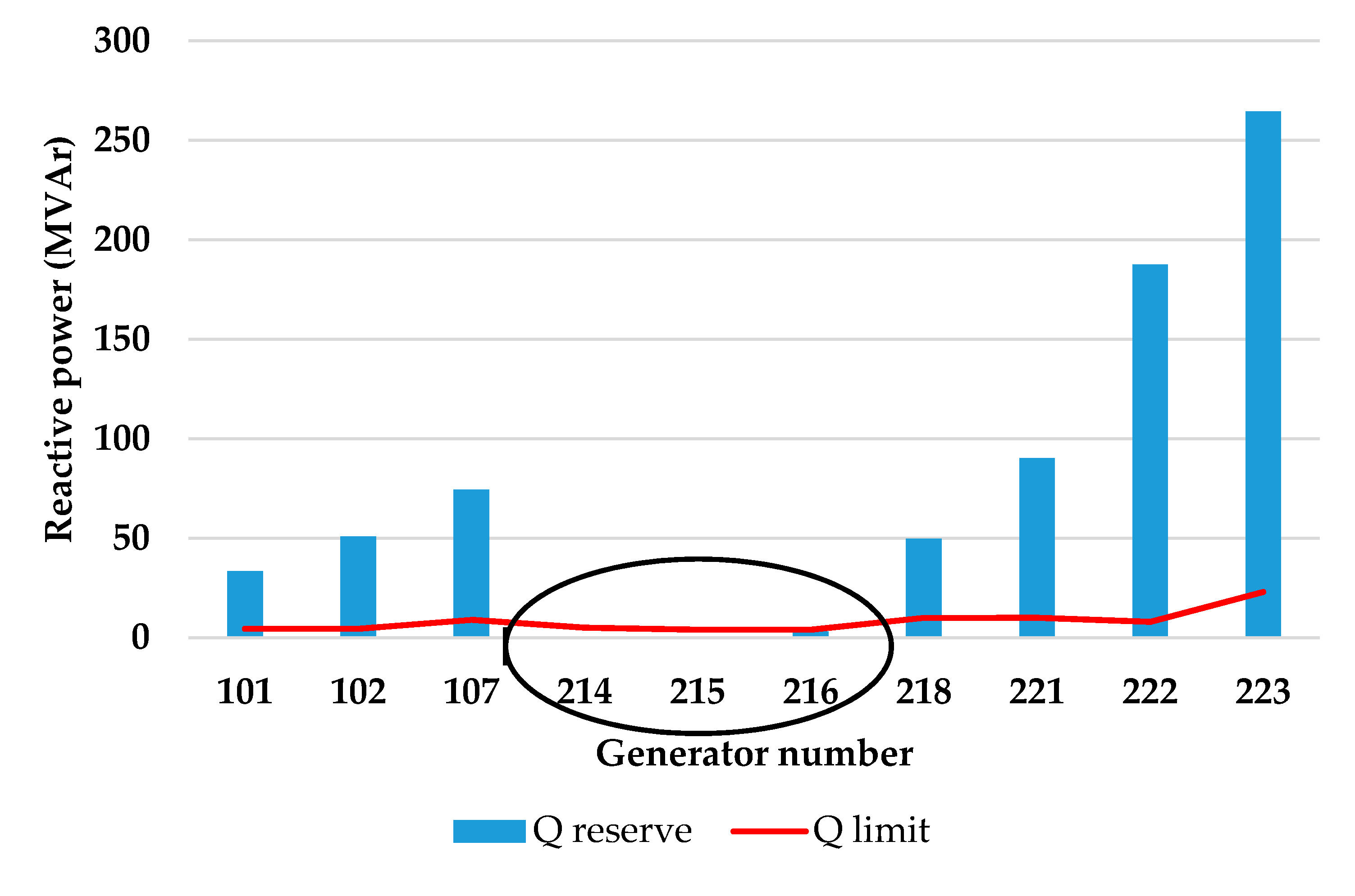
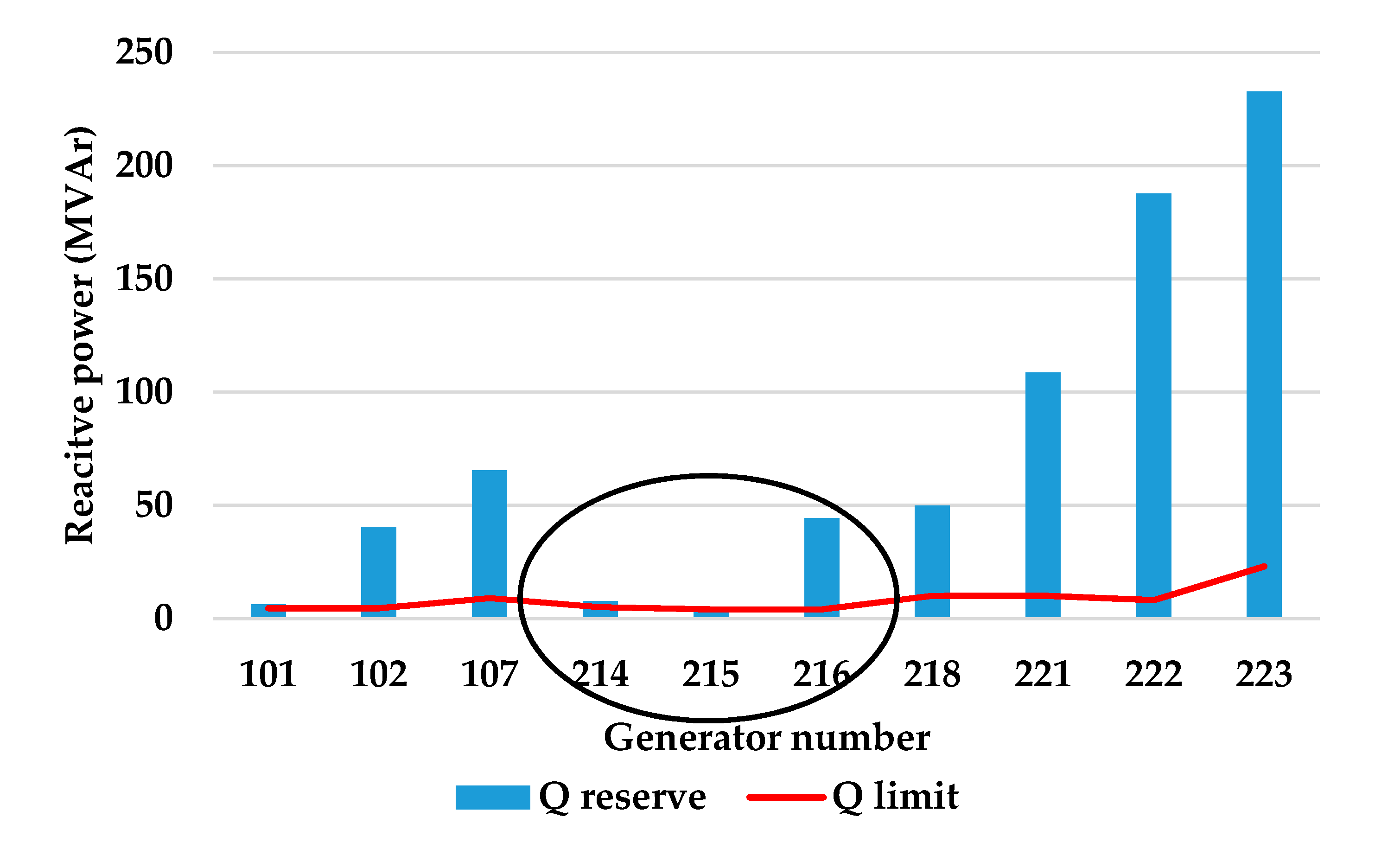
Figure 4 shows the generator reactive power reserve of each bus. The red line in
Figure 4 represents the reactive power reserve limit of each generator. In this simulation, 5% of the rated capacity of each generator is set to the reactive power reserve limit. It can be confirmed that the No. 214, 215, and 216 buses have not secured the reactive power reserve as much as the reactive power reserve limit. Since the generators of the No. 214 and 215 buses do not have any reserves, they cannot be used as a reactive power source in an emergency. In addition, since these generator buses are outputting maximum reactive powers, they act as a PQ-bus.
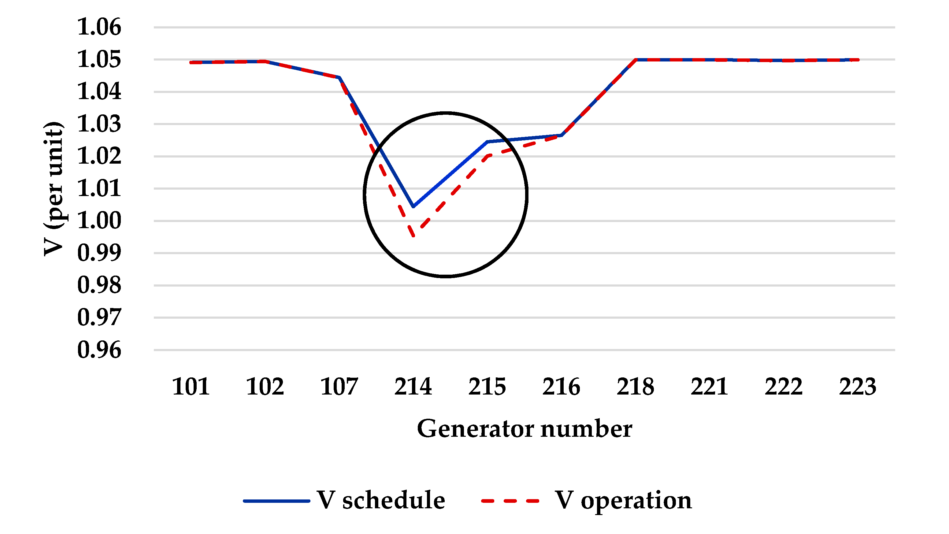
Figure 5 shows that the operating voltage and the schedule voltage of the No. 213 and 214 buses differ.
Targeting the No. 214 and 215 buses that have the gap between operational voltage and target voltage, the tap-voltage sensitivity was analyzed to adjust their voltages, and the result is as given in
Table 3.
The voltage sensitivity value means a change in the bus voltage with respect to the tap change. ‘0.024’ in
Table 3 means that when the tap ratio of 103–224 transformer is changed by 0.1, the voltage of No. 214 bus changes by 0.0024 p.u. The optimization problem was constructed with the sensitivity values in
Table 3, and the optimum operation point for securing the dynamic reactive power reserve was determined. First, the optimum solutions at the points where the voltages of the No. 214 and 215 buses are set to the target voltage are as given in
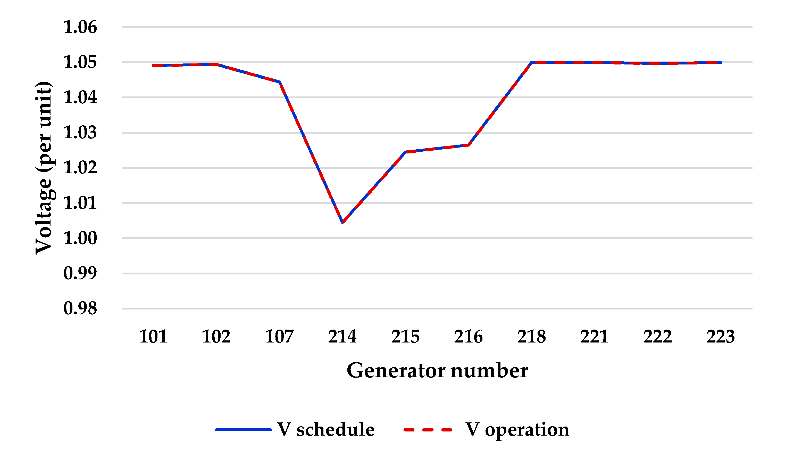
Table 4. It was confirmed (
Figure 6) that every power generation bus had become a PV bus through the optimal control, and then the optimum solution for securing the reactive power reserve of each generator was found.
After the optimal control for voltage regulation, the optimal control for securing reactive power reserve was performed. In this simulation, the reactive power reserve criterion for each generator was set as 5% of the reactive power capacity. First, the reactive power-tap sensitivities between the transformers and the generators were calculated as shown in
Table 5 for optimization problem configuration.
The reactive sensitivity value means a change of reactive power in the bus with respect to the tap change. ‘311.46’ in
Table 5 means that when the tap ratio of 103-224 transformer is changed by 0.1, the voltage of No. 101 bus changes by 31.146 MVAr.
The values of
Table 6 were obtained by solving the optimization problem. The optimal solutions of
Table 6 were applied to the transformer tap adjustments, and the power flow calculation was performed.
From the results of the power flow calculation, the first iteration of the proposed algorithm satisfies the given condition. It is possible to confirm in
Figure 7 that the target reactive power reserve has been secured through tap adjustment. The resulting reactive power reserve and voltage calculated by applying this method on the entire test system are shown as
Figure 7.
From the simulation, every bus met the voltage criterion and each generator acquired a reactive power reserve that was equal to 5% of the rated capacity. In this study, each generator was simulated to have 5% reactive power reserve, but the system operators may set different reactive power reserve criteria to increase the penetration of renewable energy more effectively according to their judgment.
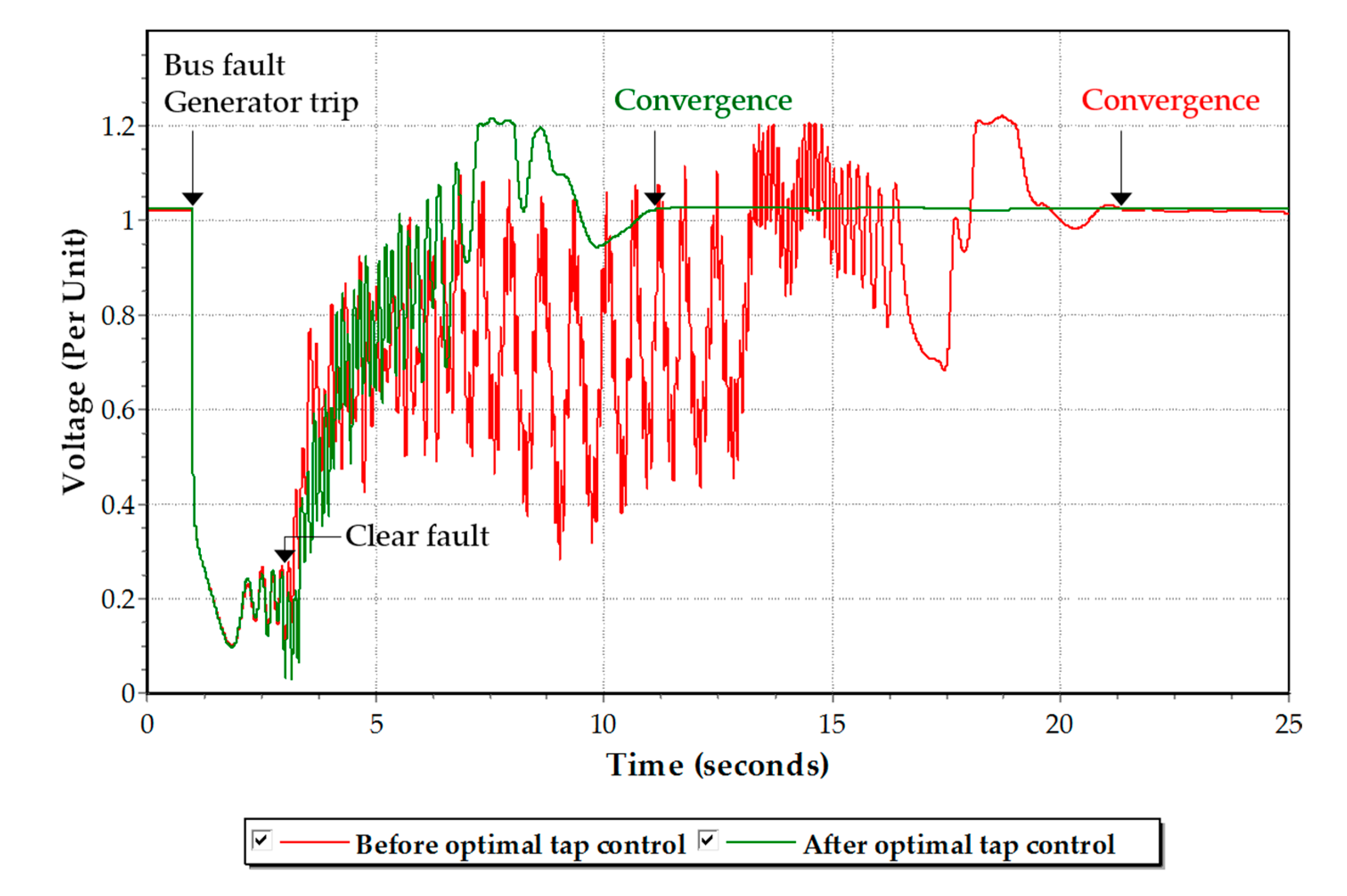
Dynamic simulation was performed to confirm the dynamical effect due to securing the reactive power of generators, and the result is shown in
Figure 8. The bus fault and generator trip on No. 221 bus was simulated to affect No. 215 bus, which is connected with renewable energy. Dynamic simulations of the cases before and after securing reactive power through the optimal tab control were observed in No. 215 bus. A disturbance was made at 1 s and a fault was removed at 3 s to cause the oscillation of the voltage in dynamic simulation. In the case before the optimal tap control, the voltage converges at about 22 s. On the other hand, in the case after the optimal tap control, the voltage converges at about 12 s. There is a long-time difference of about 10 s between the two simulations. Therefore, this result shows that securing the generator reactive power through optimal OLTC control contributes to securing dynamic voltage stability.
5. Conclusions
In this paper, we propose a method to improve the penetration rate of renewable energy through the improvement of power system operation and computing technology in a scenario where renewable energy supply is expected to increase rapidly. A method for improving the system penetration of renewable energy was proposed in terms of the voltage and reactive power to increase the system penetration of renewable energy. The original contribution of this paper is that the proposed computing scheme simultaneously controls several OLTCs that have a complicated effect on the voltages and reactive power of the various buses, thereby ensuring reactive power resources which have quick response characteristics.
Here, we present a method that allows generators with a rapid response characteristic to secure the reactive power reserve by adjusting the tap of a transformer with a slow-response characteristic. The reactive power reserve will be increased or decreased depending on the method used to adjust the transformer tap. The proposed method includes a technique that performs an optimal tap adjustment using the reactive power between the transformer tap and generator bus along with voltage sensitivities. A convex optimization problem was constructed to find the optimal solution quickly and accurately by making it suitable for use in online real-time system operations.
From the simulation results, it was possible to confirm that the desired voltage and reserve were achieved by effectively adjusting the transformer tap depending on the sensitivity levels. Furthermore, a dynamic reactive power reserve with a fast response characteristic was secured to verify the response of reactive power to changes in renewable energy. Dynamic simulation results show that securing the reactive power of a generator with fast response characteristics improves dynamic voltage stability.
We expect such a method to contribute in improving the penetration of renewable energy while effectively adjusting the voltage and securing the reactive power reserve by rapidly adjusting the tap in an actual system, as well as in an online environment. In particular, it is expected that it will be able to utilize the optimal OLTC tap control in real-time online by installing it in the energy management system so as to effectively accommodate the renewable energy that will increase gradually in the future.


