Abstract
To study the bearing capacity of large width-to-height ratio (LWHR) wind power spread foundations on onshore sandy soils, this study takes a 2 MW unit foundation of a specific wind farm as the object, conducts its sustainable design optimization, structural design and bearing capacity analysis, and explores internal force variation patterns of the structure and foundation. First, it investigates interactions among foundation soil stiffness, foundation deformation, and width-to-height ratio, and proposes the ratio can be slightly over 2.5 under specific geological conditions. Then, it verifies the foundation’s design and bearing capacity via code-based methods and uses ABAQUS to build an integrated finite element model (foundation, reinforcement, foundation ring, soil) for analyzing the mechanical behavior of the overall structure and key components. Finally, it focuses on bending moments of the foundation’s top/bottom slab reinforcement and reaction force distribution, and compares results from code formulas, commercial software, and finite element analysis. The results show that foundation deformation relates to the outer cantilever’s width-to-height ratio, reaction force magnitude, and soil stiffness. Soil stiffness impacts the linear distribution of reaction forces more significantly than the ratio—when soil stiffness is smaller, reaction forces still meet the linear assumption even if the ratio exceeds 2.5 within a range; when larger, they differ greatly. Under specific sandy soils (bearing stratum capacity < 300 kPa), the LWHR foundation meets wind turbine requirements, and its foundation ring’s punching shear resistance complies with standards (considering uplift-resistant reinforcement). For coarse sand bearing strata, the foundation’s bottom pressure follows linear distribution per code, and code formulas apply. However, the LWHR scheme is not fully suitable for complex geology or other foundation types, whose applicability needs comprehensive analysis.
1. Introduction
With the rapid development of the global wind power industry, balancing the safety and cost-effectiveness of wind power support structures has become a key issue in design [1,2], which is particularly reflected in the design and optimization of onshore spread foundations [3,4]. When concrete spread foundations are used in geological conditions with weak foundation bearing capacity, the increase in wind turbine capacity and load necessitates larger bottom dimensions of the spread foundations to avoid issues such as the increased costs associated with group pile foundations. In such cases, a problem arises where the width-to-height ratio of the cantilever end of the foundation exceeds 2.5. Taking China as an example, its current Code for Design of Building Foundation (GB50007-2011) [5] and Code for Design of Wind Turbine Foundation in Onshore Wind Farm Engineering (NB/T 10311-2019) [6] require that the width-to-height ratio of the foundation does not exceed 2.5, based on the assumption of a linear distribution of foundation base reaction. Figure 1 shows the specific requirements in the relevant specifications. To meet this requirement, it is often necessary to increase the diameter of the foundation pedestal or the thickness of the base slab, which leads to higher consumption of steel reinforcement and concrete. The code requirement that the width-to-height ratio should not exceed 2.5 aims to ensure a linear distribution of the foundation base reaction and to avoid calculation errors and design uncertainties resulting from a nonlinear distribution due to an excessively large ratio. However, this requirement is not a prerequisite for the safe bearing capacity of the concrete spread foundation itself.
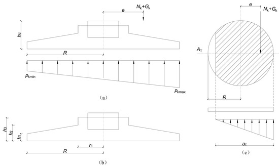
Figure 1.
Relevant requirements in the design specifications [6]. (a) Found structural shape parameters. (b) Schematic diagram of the foundation bottom not detached from the foundation. (c) Schematic diagram of the detachment of the foundation bottom from the foundation.
Neither the American Concrete Code (ACI 318-11) [7] nor the European Code for Design of Concrete Structures (EN 1992-1) [8] specifies a clear limit for the width-to-height ratio. Based on the actual load-bearing behavior of concrete foundation slabs, they are treated as cantilever plates for calculating the cross-sectional bending moment, with the base reaction assumed to follow an approximately linear distribution. Previous studies [9] have indicated that when the width-to-height ratio of a spread foundation is ≤4.0 and the foundation is under slight eccentric compression, the base reaction exhibits a “wave-shaped” nonlinear characteristic under high loads, as shown in Figure 2. However, the overall variation is slight, and no “funnel-shaped” distribution occurs as the foundation soil approaches its ultimate bearing capacity. Therefore, the base reaction can still be considered to follow a linear distribution for calculation purposes. Loading tests on foundations with different width-to-height ratios in sandy soil show that under axial compression, spread foundations with larger width-to-height ratios (3.0 and 4.0) exhibit better ductility. These foundations can work in collaboration with the soil, demonstrating a strong capacity for deformation adjustment, and their ultimate load is slightly higher than that of specimens with width-to-height ratios of 2.0 and 2.5 [10]. Through 16 sets of model tests and ABAQUS simulations, Li et al. [11] found that the width-to-height ratio (1.5–4) and hypotenuse slope (10°–30°) significantly affect the bearing capacity. They proposed a design formula incorporating the effective width correction coefficient k and the slope correction coefficient j and further established a modified section reinforcement model suitable for the force calculation of isolated spread concrete foundations with large width-to-height ratios. Additionally, several studies from various sources have pointed out that the actual base reaction of foundations is neither uniform nor linearly distributed [12,13,14], and foundation structures with large width-to-height ratios have already been applied in practical engineering [15,16]. Meanwhile, in addition to being related to the width-to-height ratio of the foundation’s outer cantilever end, foundation deformation is also associated with the magnitude of foundation reaction forces and foundation soil stiffness; however, the specific variation patterns remain unclear.
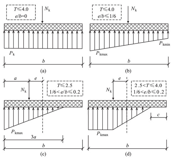
Figure 2.
The simplified method of contact pressure under spread foundations [9]. (a) T ≤ 4.0, e/b = 0. (b) T ≤ 4.0, e/b ≤ 1/6. (c) T ≤ 2.5, 1/6 ≤ e/b ≤ 0.2 (d) 2.5 < T ≤ 4.0, 1/6 ≤ e/b ≤ 0.2.
In summary, existing studies indicate that the current practice of uniformly limiting the foundation width-to-height ratio to below 2.5 without distinguishing between geological conditions and load scenarios is not entirely reasonable, and it is particularly prone to causing material waste—a key concern in sustainable design optimization. Therefore, there is an urgent need to conduct in-depth research on the relationship among foundation soil stiffness, foundation deformation, and foundation width-to-height ratio. To address this issue, this study first clarifies that the distribution law of foundation base reaction forces has a closer relationship with foundation soil stiffness by comparing and analyzing the variations in foundation base reaction forces between conventional foundations and foundations with a large width-to-height ratio under different foundation soil stiffness conditions. Specifically, when the foundation soil stiffness is relatively smaller than the foundation stiffness, the distribution of foundation soil reaction forces basically satisfies the linear assumption even if the foundation width-to-height ratio exceeds 2.5. Based on the outcomes of this theoretical research and taking the foundation of a 2 MW unit in an actual wind farm project as an example, a comprehensive analysis was conducted on the scheme of adopting a foundation with a large width-to-height ratio to avoid increasing concrete consumption—an essential goal of sustainable design optimization. This analysis clarifies the variation patterns of the mechanical behavior of the foundation structure and the underlying soil under combined loads. The research conclusions can provide a reference for the design of spread foundations with an excessive width-to-height ratio under sandy soil geological conditions similar to those in the case study.
2. Study on the Distribution Law of Foundation Base Reaction Forces
The requirements for the limit of foundation width-to-height ratio in national codes worldwide are mainly to ensure that the foundation base reaction forces follow a linear distribution. However, when the height of the foundation’s variable cross-section is reduced for foundation optimization, it may be difficult to meet this condition. To clarify the interaction relationship among foundation soil stiffness, foundation deformation, and foundation width-to-height ratio, the foundation of a 2 MW unit was taken as an example for analysis. The target wind farm is located in a sandy soil geological area, and the actual stiffness of the foundation and foundation soil was considered in the calculation. After designing the foundation according to the unit load, from the perspective of meeting force-bearing requirements and considering economy, the foundation width-to-height ratio was determined to be 3.23 (which is greater than 2.5), with specific dimensions shown on the left side of Figure 3. To comply with the code requirement on the limit of foundation width-to-height ratio, the height of the foundation’s h2 needed to be increased from 2.2 m to 2.85 m; at this point, the foundation width-to-height ratio was 2.49 (which is less than 2.5), and the specific dimensions are shown on the right side of Figure 3. Nevertheless, increasing the foundation size would lead to a 14.3% increase in material consumption.
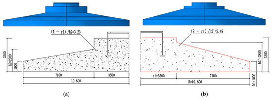
Figure 3.
Foundations with Two Different Width-to-Height Ratio Sizes. (a) (R − r1)/h2 = 3.23. (b) (R − r1)/h2 = 2.49.
To investigate the extent to which geological conditions and width-to-height ratio affect the foundation base reaction forces, the characteristic values of the bearing capacity of the sandy soil bearing stratum at the foundation base were set to 300 kPa, 600 kPa, and 900 kPa, respectively. The finite element method was adopted to conduct a comparative analysis of the foundation soil reaction forces of the two foundation sizes. The contact stresses on the most unfavorable central axis of the soil at the base of the two foundation sizes were statistically analyzed, and the results are shown in Figure 4 and Figure 5. It can be concluded that compared with the foundation width-to-height ratio, the foundation soil stiffness has a more significant impact on whether the foundation soil reaction forces follow a linear distribution. When the foundation soil stiffness is relatively small, the foundation soil reaction forces of both foundations (with different width-to-height ratios) exhibit a good linear distribution pattern, meaning the width-to-height ratio has little influence at this point. As the foundation soil stiffness increases, the foundation soil reaction forces in the middle part of both foundations (with different width-to-height ratios) begin to increase gradually, showing a significant deviation from the linear distribution assumption.
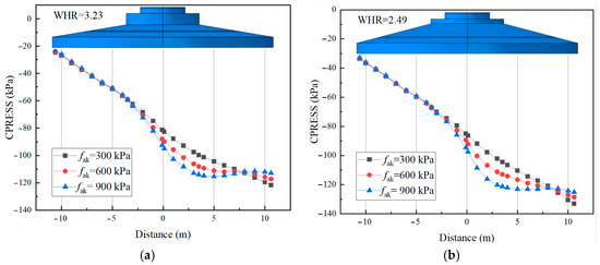
Figure 4.
Statistics of Foundation Reaction Forces with Different Width-to-Height Ratios (a) WHR = 3.23; (b) WHR = 2.49.
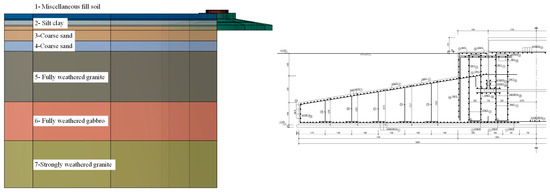
Figure 5.
The structural design of the foundation (a) Soil layer distribution. (b) Dimensions and reinforcement details of the spread foundation.
From the above analysis, it can be seen that when the foundation soil stiffness is relatively smaller than the foundation stiffness, even if the foundation width-to-height ratio exceeds the limit of 2.5 within a certain range, the distribution of foundation soil reaction forces still basically meets the linear assumption. In contrast, when the foundation soil stiffness is relatively larger than the foundation stiffness, the foundation soil reaction forces deviate significantly from the linear distribution assumption. Therefore, when optimizing the design of spread foundations in bearing strata with relatively weak foundation soil stiffness, the requirement that the foundation width-to-height ratio must be less than 2.5 can be appropriately exceeded to improve the economy of the foundation. However, special analytical calculations must be conducted, and the force-bearing requirements of the foundation structure must be satisfied.
3. Sustainable Design Optimization of Wind Power Foundation with LWHR
3.1. Structural Dimension Design for the Spread Foundation
In an onshore wind farm, wind turbines with a single-unit capacity of 2 MW are used, and the load values of the turbines during the operation period are provided in Table 1. The foundation-bearing stratum consists of coarse sand. Based on a comprehensive analysis of engineering geological drilling, standard penetration tests, and laboratory tests on soil samples, the characteristic value of the foundation bearing capacity of the bearing stratum is determined to range from 240 kPa to 300 kPa. Additionally, the saturated sand at the site will not liquefy under a 7-degree seismic intensity. The bottom foundation structure uses a ring-type spread foundation (annular). A preliminary design of the foundation structure is carried out in accordance with current codes and standards. However, to balance safety and economy, it is proposed to avoid installing pile foundations; instead, the bearing requirements of the foundation and the ground bearing capacity are met by increasing the width-to-height ratio of the foundation. For the bottom foundation structure (ring-type spread foundation, annular), the pedestal diameter is 7 m, the foundation diameter is 21.2 m, the total height of the foundation is 3.3 m, and the embedment depth is 3.2 m. The outer overhang of the base slab is 7.1 m, the thickness of the outer edge of the base slab is 1 m, and the thickness of the base slab at the pedestal is 2.2 m. The concrete strength grade of the foundation is C40, and the primary reinforcement is HRB400E. The concrete cover thickness at the bottom of the foundation is 80 mm, while that at the top and side surfaces is 50 mm. The radius of the foundation ring is 2.15 m, with an embedment depth of 1.79 m, and the distance from the bottom flange to the base slab is 1.51 m. The wall thickness of the foundation ring is 48 mm, the outer edge width of the flange is 225 mm, the inner edge width is 227 mm, and the thickness of the lower flange is 95 mm. Under these conditions, the width-to-height ratio of the foundation, calculated as (R − r1)/h2 is 3.23, which is greater than 2.5. The basic dimensions of the foundation structure are shown in Figure 5.

Table 1.
Standard values of wind turbine operating loads.
3.2. Bearing Mode of SPBF
3.2.1. Calculation of Foundation Base Reaction
Under the standard combination of normal operating load conditions, when the circular foundation is subjected to eccentric loads, the calculated maximum and minimum reaction force values at the bottom of the foundation are as follows:
121.74 kPa , at which value the foundation bearing capacity meets the requirements;
39.85 kPa > 0, indicating that no separation occurs between the foundation base and the ground, which satisfies the requirements.
Under the standard combination of extreme load conditions, when the circular foundation is subjected to eccentric loads, the maximum reaction force at the bottom of the foundation is 171.97 kPa , which meets the foundation bearing requirements; meanwhile, the minimum reaction force is −10.55 kPa < 0, indicating that the foundation base has lost contact with the ground, and further calculation of the separated area is required. For spread foundations or beam-slab foundations, when eccentric loads act outside the core area and result in partial separation of the foundation base, provided the separated area does not exceed 1/4 of the total base area, the pressure at the base of the circular foundation for wind turbines can be calculated using the following formula:
The ratio of the separated area to the total base area is: Separated/A = 3.27% < 25%, which meets the requirements.
3.2.2. Calculation of Overturning Resistance Stability
Under the fundamental combination of normal operating load conditions, the foundation overturning moment Mk is 38,277.77 kN·m, and the foundation anti-overturning moment MR is 302,157.52 kN·m. Under this condition, the anti-overturning safety factor of the foundation, calculated as Mk/MR is 7.89, which is greater than 1.6, meeting the requirements. Under the fundamental combination of extreme load conditions, the foundation overturning moment Mk is 85,322.46 kN·m, and the foundation anti-overturning moment is kN·m. Under this condition, the anti-overturning safety factor Mk/MR is 3.54, which is greater than 1.6, satisfying the requirements.
3.2.3. Calculation of Sliding Resistance Stability
Under normal operating load conditions, the foundation sliding force FS is 388.22 kN, and the anti-sliding force is 11,402.17 kN. For safety, the friction coefficient between the foundation base and the ground is taken as 0.4, which is the lower limit for medium-soft rock. Under this condition, the anti-sliding safety factor of the foundation, calculated as FR/FS, is 29.37, which is greater than 1.3, meeting the requirements. Under extreme load conditions, the foundation sliding force FS is 851.80 kN, and the anti-sliding force is 11,389.60 kN. The anti-sliding safety factor FR/FS is 13.37, which also exceeds 1.3, satisfying the requirements.
3.3. Calculation of Foundation Reinforcement
The reinforcement calculation for the top and bottom surfaces of the foundation slab is conducted under the fundamental combination of extreme load conditions. Specifically, the reinforcement arrangement of the foundation slab shall be determined based on flexural calculation. The bending moment for the reinforcement on the bottom surface can be calculated by considering the slab as a cantilever member under a uniformly distributed load. The details and summary of the reinforcement calculation for the foundation structure are provided in Table 2.
Table 2.
Statistics of foundation slab reinforcement.
3.4. Calculation of Uplift Resistance and Local Compression of Foundation Ring
The lower flange ring of the foundation is divided into 48 equal segments, and one segment is selected for the uplift check. The tensile force on this segment is 18,70,152 N. According to the design drawings, a total of 4 circumferential uplift-resistant steel bars with a diameter of 32 mm are arranged in this region, providing an uplift resistance of 2,315,520 N. Since the uplift resistance provided by the steel bars is greater than the tensile force exerted on the foundation ring segment, the uplift resistance requirement is satisfied.
Similarly, taking 1/48 of the foundation ring for compression analysis, the local pressure Fl is 3,293,847.48 N. The effective base area Ab for local compression is determined based on the principles of concentricity and symmetry between the local compression zone and the supporting area. The local compressive resistance is calculated as 6,208,334.50 N. Therefore, the concrete compressive capacity of the lower flange ring meets the design requirements.
3.5. Calculation of Punching Shear
3.5.1. Calculation of Downward Punching Shear of Pedestal
The average reaction force at the foundation base is 97.47 kPa. The area outside the scope of the downward punching cone of the pedestal is calculated as follows: A1 = 3.14 × (10.62 − 5.72) = 250.79 m2. Under the action of local loads or concentrated reactions, the punching shear capacity Fl of the slab without stirrups or bent-up bars is 24,444.46 kN. Under this condition, the punching shear resistance provided by the concrete at the foundation pedestal is = 65,354.19 kN, resulting in a safety factor against downward punching shear of 2.67, which meets the required criteria.
3.5.2. Downward Local Punching Shear of Lower Flange
Vertical uplift-resistant reinforcements (Grade 8 and Grade 9) are provided around the lower flange of the foundation ring. Taking into account the contribution of these reinforcements, the reinforced concrete structure around the foundation ring can resist a downward punching shear force of 70,038 kN. Incorporating a structural safety factor of 1.1, the design value of the maximum downward vertical punching shear force for the foundation ring is 59,686 kN. Under this condition, the anti-uplift safety factor is 1.17, which meets the requirements.
3.5.3. Upward Local Punching Shear of Lower Flange
When calculating the upward punching shear of the lower flange of the foundation ring, the friction between the side wall of the foundation ring and the foundation concrete is neglected. The calculation is performed assuming that all the upper distributed loads are transmitted to the bottom flange, and the calculation diagram is shown in Figure 6. Under this condition, accounting for the contribution of the No. 8 and No. 9 reinforcements, the reinforced concrete structure around the foundation ring can resist an upward punching shear force of 58,760 kN. With a structural safety factor of 1.1, the maximum upward vertical punching shear force of the foundation ring is 17,792 kN. Thus, the anti-uplift safety factor is 3.30, which meets the requirements.
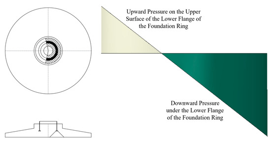
Figure 6.
Upward punching shear range and force-bearing schematic of the lower flange.
3.6. Calculation of Bottom Slab Cracks
Crack width checking shall be performed according to the standard combination of normal operating load conditions, with the requirement that the maximum crack width of the foundation shall not exceed 0.2 mm under this condition. Based on the specific dimensions and load conditions of the foundation structure, the calculated maximum crack width of the foundation is as follows:
Therefore, the crack width of the foundation meets the requirements under this load condition.
4. Foundation Stress Analysis Based on Finite Element Method
4.1. Overall Finite Element Model
Based on the force calculation results for the foundation structure in Section 3, all indicators meet the requirements except for the width-to-thickness ratio of the cantilever slab outside the foundation, which is 3.23 and exceeds the specification limit of 2.5. To further investigate the influence of the large width-to-thickness ratio on the bearing capacity of wind power spread foundations on sandy soil, a refined three-dimensional finite element model including the soil was established using finite element software. A detailed analysis was conducted on the stress conditions of the foundation concrete, reinforcement, foundation ring, and foundation soil. The overall finite element model is shown in Figure 7. In the finite element model, the Mohr-Coulomb plastic model [16,17,18] was adopted for the soil, which was modeled using C3D8R elements. The material properties of the soil were set in layers according to the geological survey report, with the internal friction angle of coarse sand being 33°. A fully fixed constraint was applied to the bottom surface of the soil, while horizontal constraints were imposed on the side surfaces. Frictional contact was used between the soil and concrete, with a friction coefficient of 0.3. The foundation ring is modeled using solid elements, and frictional contact is adopted between the foundation ring and concrete with a friction coefficient of 0.5. For concrete, the Concrete Damaged Plasticity (CDP) elastoplastic constitutive model [19,20,21] is employed, and the reinforcement is embedded in the concrete using Truss elements. The total number of unit meshes in the overall model is 120,869, among which the number of soil meshes is 47,659, concrete meshes is 30,066, reinforcement meshes is 30,528, and foundation ring meshes is 12,616.
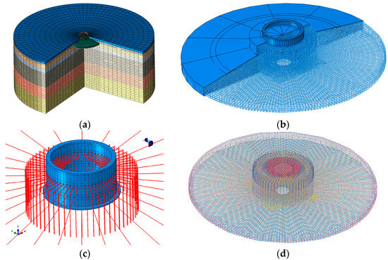
Figure 7.
Refined finite element model of the foundation. (a) Overal model. (b) Foundation model. (c) Ring and punching reinforcement. (d) Reinforcement.
4.2. Stress Analysis of Concrete
4.2.1. Compressive Stress of Concrete
The compressive stress nephogram of the spread foundation is shown in Figure 8a. The location of the maximum compressive stress in the foundation is the concrete on the outer side of the upper surface of the bottom flange of the foundation ring, with a maximum compressive stress value of 6.080 MPa. This is less than the design compressive strength of C40 concrete (fc = 19.1 MPa), indicating that it meets the requirements. The compressive damage nephogram of the concrete is shown in Figure 8b. The damage factor ranges from 0 to 1; a value of 0 indicates no plastic damage, while a value of 1 or close to 1 indicates that the concrete has lost its load-bearing capacity, leading to complete failure. Under these working conditions, the maximum compressive damage factor of the foundation is 0.0002128, indicating that the entire foundation structure exhibits no compressive damage and maintains good integrity.
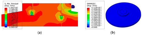
Figure 8.
Compressive stress nephogram of foundation concrete. (a) Compressive stress nephogram. (b) Compressive plastic damage nephogram.
4.2.2. Tensile Stress of Concrete
The tensile stress nephogram of the spread foundation is shown in Figure 9a. The maximum tensile stress occurs in the concrete on the inner side of the bottom flange of the foundation ring, with a value of 2.408 MPa, which slightly exceeds the standard tensile strength value of C40 concrete (ftk = 2.39 MPa). As indicated by the reinforcement check in Section 3.2 and the crack width verification in Section 3.5, through reasonable reinforcement layout, the crack width of the foundation base slab remains under 0.2 mm, thereby meeting the requirements. The stress nephogram of the joint between the foundation pedestal and the spread angle is presented in Figure 9b. The maximum tensile stress at the bottom of the cantilever slab is 1.439 MPa, and no cracking occurs under this working condition.
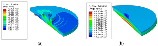
Figure 9.
Tensile stress nephogram of foundation concrete. (a) Tensile stress nephogram. (b) Compressive plastic damage nephogram.
The tensile damage nephogram of the concrete is shown in Figure 10. The local tensile damage factor of the foundation reaches 0.98, indicating a certain degree of tensile plastic damage; however, since the reinforcement in the base slab participates in load-bearing, no through cracks are ultimately formed. Under extreme load conditions, the local tensile stress at the foundation base slab exceeds the standard limit. However, when the cracking extends to the bottom layer of the base slab reinforcement, the crack propagation stops; the reinforcement then participates in force-bearing, and no through cracks are formed. In addition, as calculated in the aforementioned “3.6 Calculation of Bottom Slab Cracks”, the foundation base slab does not crack under normal operating conditions, which meets the requirements permitted by the code.
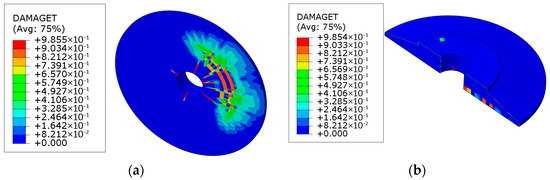
Figure 10.
Tensile plastic damage nephogram at the bottom of the foundation concrete. (a) Bottom view of the tensile damage plane. (b) Cross-sectional view of the tensile damage surface.
4.3. Stress Analysis of Steel Reinforcement
The overall Mises stress nephogram of Rebars ①~④ in the foundation base slab is shown in Figure 11. Among these four types of rebars, Rebar ② exhibits the highest stress, with a value of 122 MPa, which is below the design yield strength of HRB400 steel reinforcement, thereby meeting the design requirements. The overall Mises stress nephogram of Rebars ⑤~⑦ in the foundation top slab is presented in Figure 12. Among these five types of rebars, Rebar ⑤ has the maximum stress, reaching 131 MPa, which is less than the design yield strength of HRB400 steel reinforcement, thus satisfying the design requirements.
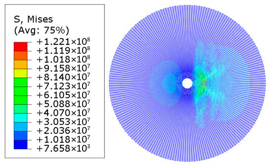
Figure 11.
Reinforcements ①~④.
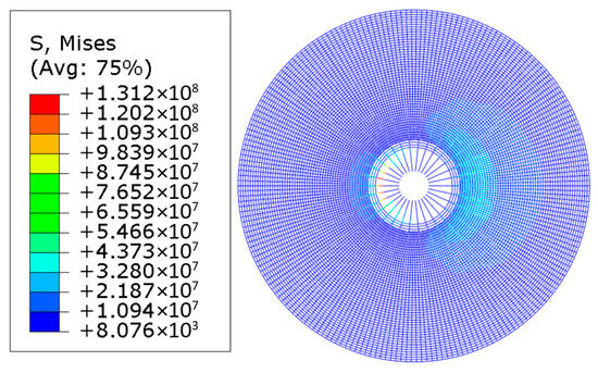
Figure 12.
Reinforcements ⑤~⑦, ㉔, ㉕.
The overall stress nephogram of Rebars ⑧~⑩ in the foundation base slab is shown in Figure 13. Among these three types of rebars, Rebar ⑧ shows the highest stress, with a value of 189.6 MPa. The statistics of the overall and individual Mises stress for Rebars ⑭~⑱ and ㉖~㉛ around the foundation ring are provided in Figure 14. Among these 11 types of rebars, Rebar ⑮ carries the maximum stress, at 189.7 MPa. The stress values of all the aforementioned rebars are below the design yield strength of HRB400 steel reinforcement, meeting the design requirements.
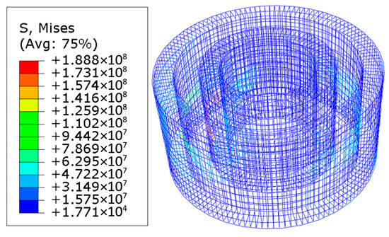
Figure 13.
Reinforcements ⑧~⑩.
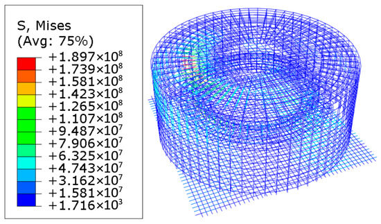
Figure 14.
Reinforcements ⑭~⑱, ㉖~㉛.
In summary, the stresses in the rebars throughout all sections of the foundation structure are within the required limits, and a significant safety margin remains under the basic load combination at the ultimate limit state of bearing capacity.
4.4. Stress Analysis of Foundation Soil
4.4.1. Foundation Soil Bearing Capacity
Under the standard combination of the serviceability limit state, the maximum compressive stress of the coarse sand in the foundation soil in contact with the foundation bottom is −121.9 kPa (Figure 15a), which is less than the designed foundation bearing capacity (the characteristic value of the coarse sand foundation bearing capacity is 240 kPa), thus meeting the requirements. Under this working condition, the deviation between the numerical simulation result of the foundation stress (−121.9 kPa) and the formula calculation result (−121.74 kPa) in Section 3.2.1 is minimal. Under the standard combination of the ultimate limit state of bearing capacity, the maximum compressive stress of the coarse sand in the foundation soil in contact with the foundation bottom is −180.3 kPa (Figure 15b), which is also less than the designed foundation bearing capacity (characteristic value: 240 kPa), satisfying the requirements. Under this working condition, the numerical simulation result of the foundation stress (−180.3 kPa) is close to the formula calculation result (−174.96 kPa) in Section 3.2.1. This indicates that in this sandy soil foundation, although the width-to-height ratio of the foundation exceeds 1.3 times the code requirement, the reaction force at the foundation bottom still exhibits a relatively uniform linear distribution, and the standard formula method remains applicable in this case.
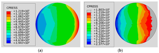
Figure 15.
Contact stress nephogram between foundation and ground (a) Serviceability working condition (b) Ultimate limit state condition of bearing capacity.
4.4.2. Foundation Separation Rate
As shown in Figure 16a, based on the contact pressure (CPRESS) between the foundation bottom and the foundation soil, no separation occurs under the normal operating condition, meeting the requirements. Under the ultimate limit state condition of bearing capacity, a small separation area is observed at the foundation bottom, as illustrated in Figure 16b. The separation area ratio is 4.45%, which is below the limit value of 25%, thus also satisfying the requirements.
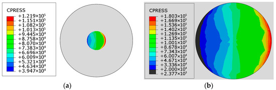
Figure 16.
Foundation detachment area (a) Serviceability working condition (b) Ultimate limit state condition of bearing capacity.
4.4.3. Foundation Inclination Rate
Under the standard combination of the serviceability limit state, the maximum vertical displacement of the foundation is −2.414 mm, as shown in Figure 17a. The tilt rate at the foundation bottom is 0.15‰, which is below the limit requirement of 3‰ (applicable for H > 100 m), thus meeting the specifications. The vertical displacement at the bottom flange of the tower tube is −2.345 mm, with a corresponding flange tilt rate of 0.59‰, as presented in Figure 17b.
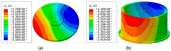
Figure 17.
Vertical displacement nephogram (a) Foundation (b) Foundation Ring.
5. Stress Analysis of Key Parts Based on Different Algorithms
It can be seen from the aforementioned calculation results that the foundation structure can meet the operational requirements of the unit in terms of load-bearing capacity. However, due to the large diameter of the foundation, the width-to-thickness ratio at the cantilever slab of the foundation spread angle exceeds the recommended limit of 2.5 specified in the code. Furthermore, detailed finite element analysis conducted in the second part shows that both the foundation and the foundation soil continue to meet the operational requirements of the wind turbine under load. To further quantify the differences in calculation results for key sections among the code-based formula method, integrated software, and the refined finite element method, a detailed comparative analysis is carried out herein focusing on two critical aspects: the bending moment of reinforcement in the top and base slabs of the foundation, and the distribution of the foundation reaction force.
5.1. Reinforcement Bending Moment of Foundation Top and Bottom Slabs
The bending moment values calculated using the specification formula, the integrated software, and the refined finite element method are summarized in Table 3. It can be seen from the table that, for the reinforcement design of the foundation top slab and base slab, both the cross-sectional bending moment design values and the radial reinforcement bending moment design values obtained from the finite element model (as shown in Figure 18) are smaller than those calculated by the integrated software and the specification formula. Only the circumferential bending moment of the top slab (1468.07 kN·m) is slightly greater than the result from the integrated software (1459.00 kN·m). Nevertheless, the actual circumferential reinforcement area per unit length provided in the base slab is 3272 mm2/m, which is 3.937 times the calculated required value (830.97 mm2/m), thereby satisfying the load-bearing requirements.
Table 3.
Bending moment loads of the base slab.
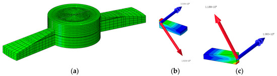
Figure 18.
Schematic diagram of bending moment extraction per unit arc length of the base slab (a) Per unit arc length at the pedestal. (b) Reinforcement bending moment extraction of the foundation base slab. (c) Reinforcement bending moment extraction of the foundation top slab.
5.2. Distribution of Foundation Base Reaction
The foundation bearing pressures calculated by the specification formula, a commercial structural design software, and the refined finite element method are summarized in Table 4. The results obtained from these methods are in close agreement, indicating that for this foundation structure, the contact pressure at the foundation base can be adequately estimated using the linear distribution assumption prescribed in the design code.
Table 4.
Foundation compressive stress at the foundation base.
6. Conclusions
(1) In addition to the width-to-height ratio of the overhanging end beyond the foundation, the foundation deformation is also related to the magnitude of the foundation reaction force and the foundation stiffness. Compared with the foundation width-to-height ratio, the foundation stiffness has a more significant impact on whether the foundation reaction force follows a linear distribution. When the foundation stiffness is relatively smaller than the reference stiffness, the distribution of the foundation reaction force basically conforms to the linear assumption even if the foundation width-to-height ratio exceeds the limit of 2.5 within a certain range. However, when the foundation stiffness is relatively larger than the reference stiffness, there is a significant difference between the foundation reaction force and the linear distribution assumption. With the increase in the foundation stiffness, the foundation reaction forces in the middle part of the foundations with the two width-to-height ratios begin to increase gradually, showing a great difference from the linear distribution assumption, findings that can provide key technical support for subsequent sustainable design optimization of foundations.
(2) Through verification using standard calculation methods and ABAQUS finite element analysis, under both normal and extreme load conditions, the overturning and sliding safety factors of the large width-to-height ratio foundation all exceed the required limits. The maximum crack width is 0.096 mm, which is less than 0.2 mm. The uplift resistance of the foundation ring and the punching shear safety factor comply with standards, and the overall bearing capacity meets the operational requirements of the wind turbine. The deviation between finite element results and standard values under both load conditions is slight. Under extreme conditions, the foundation disengagement rate is 4.45% < 25% and the inclination rate is 0.59‰ < 3‰.
(3) The differences among code-based formulas, integrated software, and refined finite element methods in calculating the bending moments of reinforcement in the top and bottom slabs of the foundation were quantitatively compared. Under the ultimate limit state of bearing capacity, the bending moments of the bottom slab and the radial direction of the top slab obtained by the finite element method are smaller than those from the code and the integrated software, with only the circumferential bending moment of the top slab being slightly larger. Nevertheless, the actual reinforcement area is 4.06 times the calculated requirement, which fully satisfies the structural load-bearing demands. At the same time, the accuracy of the finite element model is verified, offering a more precise basis for the reinforcement design of wind power foundations with a large width-to-height ratio.
(4) Based on specific soil conditions (sandy soil where the characteristic value of the bearing capacity of the bearing stratum is less than 300 kPa), this study proposes an optimization direction for the design of spread foundations: under specific geological conditions, the foundation width-to-height ratio can be slightly greater than 2.5. This optimization can improve the economy of the foundation, aligning with the core goal of sustainability by reducing unnecessary material consumption, but special analytical calculations are required to ensure that the force-bearing requirements of the foundation structure are met. It is not fully applicable to other complex geological conditions and foundation structure forms, and its application scope needs to be determined through comprehensive calculation and analysis. In the later stage, relevant research under various geological and complex geological conditions will be further carried out.
Author Contributions
Conceptualization, H.W. and X.Z.; methodology, H.H., X.Z. and L.Z.; validation, Y.L.; investigation, H.C., J.W., T.C. and C.C.; resources, X.Z. and H.W.; data curation, X.Z.; writing—original draft preparation, H.W. and X.Z.; writing—review and editing, C.Z. and Y.G.; supervision, H.W. All authors have read and agreed to the published version of the manuscript.
Funding
This research was funded by the fund of China Huaneng Group (HNKJ24-H83); State Key Laboratory of Hydraulic Engineering Intelligent Construction and Operation, Tianjin University (No. HESS-2104).
Institutional Review Board Statement
Not applicable.
Informed Consent Statement
Not applicable.
Data Availability Statement
The original contributions presented in this study are included in the article. Further inquiries can be directed to the corresponding author.
Acknowledgments
The authors acknowledge support from China Huaneng Clean Energy Research Institute and State Key Laboratory of Hydraulic Engineering Intelligent Construction and Operation (Tianjin University).
Conflicts of Interest
Huageng Hao, Liying Zhang and Yuhui Liu were employed by the company China Huaneng Group Clean Energy Research Institute Co., Ltd., owned by author Huageng Hao, Liying Zhang and Yuhui Liu. Hao Cui, Jinge Wang and Tianbao Cui were employed by the company Huaneng Jilin New Energy Development Company, owned by author Hao Cui, Jinge Wang and Tianbao Cui. Chen Chen was employed by the company Beijing Huaneng Yangtze Environmental Technology Research Institute Co., Ltd., owned by author Chen Chen. The remaining authors declare that the research was conducted in the absence of any commercial or financial relationships that could be construed as a potential conflict of interest.
Nomenclature
| hd | Height from the top surface of the foundation ring to the foundation base |
| e | Eccentricity |
| R | Radius of the foundation base |
| Nk | Vertical force standard value transmitted from the superstructure to the foundation top surface under the standard combination of load effects |
| Gk | Standard value of foundation self-weight and gravity of overlying soil on foundation under the standard combination of load effects |
| Pkmin | Minimum pressure value at the edge of the foundation base under the standard combination of load effects |
| Pkmax | Maximum pressure at the edge of the foundation base under the standard combination of load effects |
| r1 | Radius of the pedestal |
| h1 | Foundation edge height |
| h2 | Height of the foundation variable cross-section |
| h3 | Height of the pedestal |
| AT | Foundation detached area |
| ac | Compressed width of the foundation base |
| b | Section width |
| pk | Average pressure at foundation base under characteristic combination of load effects |
| T | Aspect ratio |
| a | Distance from resultant action point to edge of maximum pressure on foundation base |
| c | Foundation detached width |
| Mxy | Characteristic values of resultant moments about x-axis and y-axis horizontal axes |
| Fxy | Characteristic values of horizontal resultant forces for x-axis and y-axis |
| Fz | Characteristic Value of Vertical Force |
| Mk | Standard value of resultant moment transmitted from superstructure to foundation base under the standard combination of load effects |
| W | Section modulus of the foundation base |
| A | Cross-sectional area of the foundation base |
| fak | Characteristic value of foundation bearing capacity |
| ξ | Calculation coefficient for maxi mum pressure on the foundation base |
| MR | Overturning resistance moment un-der the basic combination of load effects |
| FS | Design value of sliding force under the basic combination of load effects |
| FR | Sliding resistance force under the basic combination of load effects |
| μ | Friction coefficient between foundation base and foundation soil |
| F1 | Design value of pressure under the foundation ring |
| Ab | Calculation base area for local compression |
| Fl | Design value of load outside the punching failure body under the basic combination of load effects |
| βh | Section height influence coefficient for punching shear capacity of pile cap |
| ft | Design value of concrete tensile strength |
| η | Influence coefficient |
| um | Perimeter of calculation section |
| h0 | Effective height of calculation section for punching failure cone of pile cap |
| ωmax | Maximum crack width calculated based on the characteristic combination or quasi-permanent combination of loads, considering the Influence of Long-Term Effects |
| αcr | Component force-characteristics coefficient |
| ψ | Strain inhomogeneity coefficient of longitudinal tension reinforcement between cracks |
| σs | Stress of ordinary longitudinal tension reinforcement in reinforced concrete members calculated by quasi-permanent load combination |
| Es | Elastic modulus of reinforcement / elastic modulus of steel bars |
| Cs | Distance from the outer edge of the outermost longitudinal tension reinforcement to the bottom edge of the tension zone |
| deq | Equivalent diameter of longitudinal reinforcement in the tension zone |
| ρte | Longitudinal tension reinforcement ratio calculated based on the effective tension concrete cross-section area |
| fc | Design value of concrete compressive strength |
| ftk | Standard value of concrete tensile strength |
| H | Hub height |
References
- Yang, H.; Tan, T.; Pan, J.; Wang, C. Research on improving the horizontal bearing performance of wind power pile foundation with added wing structure. Sustainability 2025, 17, 861. [Google Scholar] [CrossRef]
- Medeiros, I.D.S.; de Lima, D.M. Structural performance of direct foundations of onshore wind turbine towers considering SSI: A literature review. Renew. Sustain. Energy Rev. 2025, 217, 115742. [Google Scholar] [CrossRef]
- Amponsah, E.; Wang, Z.; Kwame Mantey, S. Bending-bearing behaviour of embedded steel ring-foundation connection of onshore wind turbines. Structures 2021, 34, 180–197. [Google Scholar] [CrossRef]
- Xu, Y.; Wang, H.; Zhang, L.; Deng, M.; Jiang, H.; Guo, Y.; Yang, X. Research on bearing capacity of secant piled-bucket foundation in saturated clay. Sustainability 2022, 14, 11511. [Google Scholar] [CrossRef]
- Ministry of Housing and Urban Rural Development of the People’s Republic of China. Code for Design of Building Foundation; China Architecture & Building Press: Beijing, China, 2011.
- China Renewable Energy Engineering Institute. Code for Design of Wind Turbine Foundations for Onshore Wind Power Projects; China Water & Power Press: Beijing, China, 2020.
- ACI 318-11; Building Code Requirements for Structural Concrete and Commentary. American Concrete Institute International: Farmington Hills, MI, USA, 2011.
- BSEN1992-l-1; Eurocode 2: Design of Concrete Structures: Part l-1: General Rules and Rules for Buildings. British Standards Institution: London, UK, 2004.
- Liang, X.; Wang, J.; Liang, F.; Li, Y.; Xiao, M. Study on the contact pressure distribution and simplified design method of spread foundations with high width-to-height ratio. Sichuan Build. Sci. 2019, 45, 82–87. [Google Scholar]
- Xiao, M.; Gan, H.; Liang, F.; Wang, J. Experimental study on contact pressure distribution of spread foundation with high width-to-height ratio in sandy soils. Sichuan Build. Sci. 2018, 44, 86–91. [Google Scholar]
- Li, Y.; Qin, X.; Luo, J.; Xiao, M.; Hua, C. Uplift test and design method for bearing capacity of isolated spread concrete foundation slab with large width-to-height ratio. Adv. Civ. Eng. 2018, 2018, 3672868. [Google Scholar] [CrossRef]
- Qian, Z.Z.; Lu, X.L.; Tong, R.M. Experimental study on bearing capacity of concrete spread foundation under uplift combined with horizontal loads. J. Disaster Prev. Mitig. Eng. 2012, 32, 573–578. [Google Scholar]
- Deng, Z.-W.; Fan, Z.-J.; Zhou, Y.-M.; Deng, P.-Y. Study on dynamic response characteristics of circular extended foundation of large wind turbine generator. Sustainability 2022, 14, 14213. [Google Scholar] [CrossRef]
- Cui, Q.; Zhang, Z.H.; Lu, X.L. Study of failure modes and slid surface characteristics of soils mass around enlarge base foundation. Met. Mine 2010, 39, 161–164. [Google Scholar]
- Lu, X.L.; Qian, Z.Z.; Tong, R.M. Pullout behavior of precast concrete assembly spread foundation. Eng. Mech. 2013, 30, 215–220. [Google Scholar]
- Gravett, D.Z.; Markou, G. State-of-the-art investigation of wind turbine structures founded on soft clay by considering the soil-foundation-structure interaction phenomenon—Optimization of battered RC piles. Eng. Struct. 2021, 235, 112013. [Google Scholar] [CrossRef]
- Harte, M.; Basu, B.; Nielsen, S.R.K. Dynamic analysis of wind turbines including soil-structure interaction. Eng. Struct. 2012, 45, 509–518. [Google Scholar] [CrossRef]
- Taddei, F.; Butenweg, C.; Klinkel, S. Parametric investigation of the soil-structure interaction effects on the dynamic behaviour of a shallow foundation supported wind turbine considering a layered soil. Wind Energy 2015, 18, 399–417. [Google Scholar] [CrossRef]
- Sobrinho, M.; Pimentel, M.; Magalhães, F. Nonlinear numerical modelling of onshore wind turbine foundations validated with experimental data. Eng. Struct. 2025, 336, 120441. [Google Scholar] [CrossRef]
- Martinelli, P.; Flessati, L.; Dal Lago, B.; Fraraccio, G.; di Prisco, C.; di Prisco, M. Role of numerical modelling choices on the structural response of onshore wind turbine shallow foundations. Structures 2022, 37, 442–458. [Google Scholar] [CrossRef]
- Zhang, D.; Liu, W.; Wang, F.; Yu, Z.; Wu, X.; Li, T.; Fu, K.; Magar, A.T.; Hwang, H.-J.; Xian, X. Numerical investigation on prestressed shear key splice connections for onshore wind turbine foundations. Eng. Struct. 2025, 339, 120562. [Google Scholar] [CrossRef]
Disclaimer/Publisher’s Note: The statements, opinions and data contained in all publications are solely those of the individual author(s) and contributor(s) and not of MDPI and/or the editor(s). MDPI and/or the editor(s) disclaim responsibility for any injury to people or property resulting from any ideas, methods, instructions or products referred to in the content. |
© 2025 by the authors. Licensee MDPI, Basel, Switzerland. This article is an open access article distributed under the terms and conditions of the Creative Commons Attribution (CC BY) license (https://creativecommons.org/licenses/by/4.0/).