Article

Impact of Filter Inductance on Transient Synchronization Stability of Grid-Connected Systems with Grid-Following Converters Under Voltage Sag Faults

1
School of Electrical Engineering, Shandong University, 17923 Jingshi Road, Lixia District, Jinan 250061, China
2
Electric Power Research Institute, State Grid Shandong Electric Power Co., Ltd., Jinan 250003, China
*
Author to whom correspondence should be addressed.
Sustainability 2025, 17(19), 8634; https://doi.org/10.3390/su17198634
Submission received: 7 August 2025 / Revised: 22 September 2025 / Accepted: 22 September 2025 / Published: 25 September 2025

Abstract

As renewable energy sources become more prevalent, maintaining the sustainable and reliable operation of power systems has become as a major challenge. Modern grid-connected converter systems are particularly prone to losing synchronization when encountering large disturbances, which is a huge threat to the stability of the power grid, which is mainly based on renewable energy. This paper studies the impact of filter inductors on the synchronous stability of grid-connected converter systems, hoping to help us better connect renewable energy to the power grid. First, the existing synchronization stability model of grid-following (GFL) converters is extended by incorporating filter inductance modeling. Based on this model, a mathematical relationship between the phase-locked loop’s (PLL) frequency deviation and the filter inductance at the moment of fault is established, and a predictive method for GFL frequency deviation considering filter inductance is proposed. Furthermore, the impact of filter inductance on synchronization stability is systematically investigated through two key indicators: power angle overshoot and critical fault voltage, revealing the variation trends of transient stability under different operating conditions. Finally, the analytical results are validated through Matlab/Simulink simulations, providing theoretical guidance for the design of sustainable and robust renewable energy grid integration strategies.

1. Introduction

To promote the transformation of the energy structure and achieve sustainable development, the large-scale integration of new energy sources, such as wind and photovoltaic power, has increased the penetration of electronic power devices into the power system, weakened the resistance to disturbance of the system [1,2]. Fault-induced system instability may lead to large-scale blackouts, causing significant economic losses and far-reaching social consequences. Therefore, to mitigate the risk of grid collapse during power grid faults, new energy sources must possess and maintain the capability to operate synchronized with the grid, preventing cascading disconnections [3]. In this context, the type of grid-connected converters for new energy sources and their ability to operate stably have become critical research priorities. Currently, grid-connected converters are predominantly grid-following converters (GFL) [4]. With the growing integration of renewable energy sources, leading to a relative weakening of grid strength, the risk of GFL system instability due to loss of synchronization during severe grid disturbances has become increasingly prominent. The stability issues of GFL converters have drawn increased attention, and their characteristics such as multi-time scale coupling, nonlinear dynamics, and grid interactions are being more deeply understood [5]. However, the analysis of transient stability in converters remains at a nascent stage.
In recent years, research on the synchronization stability of GFL converters has gradually evolved from analyzing only the phase-locked loop (PLL) dynamics to considering the interactions between the converter and the grid, multi-time-scale couplings, and the dynamics of control loops, especially the current control loop and outer-loop controls [6]. Under strong grid conditions, the PLL attains synchronization by monitoring the voltage at the point of common coupling (PCC) [7,8]. Since the PCC voltage remains relatively stable, the synchronization stability of the GFL grid-connected system is primarily determined by the transient characteristics of the PLL [9,10]. Under weak grid conditions, several studies have shown that the coupling between the PLL and the current control loop can significantly reduce the system’s stability margin, making simplified PLL-based models overly optimistic [11,12]. Recent studies have shown that the filter inductance not only determines the synchronization power coefficient but also significantly participates in the dynamics of the current control loop, affecting transient synchronization stability by altering the coupling between the current loop and the PLL [13,14]. While the GFL current control loop usually reacts much more swiftly than the PLL’s dynamic response, the time constant of the current loop increases accordingly when the filter inductance value is increased [15]. Under these conditions, significant coupling effects arise between the current control and PLL dynamic processes, and the impact of current control on the synchronization stability of GFL cannot be neglected [16]. Reference [17] further illuminated how the interplay among control parameters, grid impedance, and filter inductance shapes synchronization stability, and it proposed improved modeling methods and stability criteria.
Physical mechanism analysis indicates that increasing the filter inductance slows down the current loop response, reduces the synchronizing power coefficient, increases the equivalent inertia, and weakens damping, thereby enlarging power angle deviations and amplifying post-disturbance oscillations, ultimately weakening the transient stability of grid-following converter systems [18]. Consequently, the conventional GFL synchronization stability model is extended by incorporating the transient dynamics of the current control loop, resulting in a more comprehensive model that accounts for current transient process [19]. When incorporating filter inductance into the control loop of the GFL grid-connected system, its effect on system synchronization stability must be accounted for. In our previous work [20], the impact of filter inductance on the transient stability of the system is analyzed under the condition of neglected grid resistance. However, in practical power grids, neglecting grid resistance reduces system damping, lowers the critical filter inductance, and exaggerates transient responses, leading to a misjudgment of the actual transient stability [21]. Therefore, the impact of grid resistance cannot be ignored.
Building upon prior work in [20], this study assumes a moderate-penetration system with an ideal, harmonic-free grid voltage and a conventional PI current control strategy. The aim is to establish an extended GFL synchronization stability model that incorporates current transient processes to assess how filter inductance affects system synchronization stability. In Section 2, the frequency deviation during faults is derived theoretically as a function of filter inductance, using the GFL synchronization stability model with current transient effects. In Section 3, with grid resistance characteristics incorporated, the impact pattern of filter inductance on transient synchronization stability of the system is analyzed. In Section 4, the theoretical analysis results are validated through MATLAB/Simulink simulations, followed by conclusions in Section 5.

2. Necessity of Considering Filter Inductance in Synchronous Stability Analysis

To evaluate how the filter inductor influences synchronous stability, a voltage source converter (VSC)-based GFL system is adopt as an example, illustrated in Figure 1. The GFL system mainly includes PLL, current control, and pulse width modulation (PWM). The PLL employs a PI controller to regulate the q-axis component of the PCC voltage to zero, ensuring synchronization between the VSC and the grid. The current control loop generates the reference output voltage, which is then used by the PWM module to produce the gate signals for the VSC switches. In addition, since this study focuses on the overall transient characteristics of the system, a three-phase voltage dip fault is considered to highlight the effect of the filter inductance while avoiding the influence of additional complex coupling factors on the system’s overall transient behavior [22].
In the figure, U g = U g θ g = u gd + j u gq represents the grid voltage, where U g is the grid voltage magnitude and θ g is the grid voltage phase angle. U p = U p θ p = u pd + j u pq denotes the PCC voltage, with U p being the voltage magnitude at the PCC, and θ p its phase angle. U c = u cd + j u cq is terminal voltage of VSC. I = i d + j i q and I * = i d * + j i q * denote the input grid current and its comparative value, while l g and l f denote grid-side and filter inductances, respectively. θ pll and ω pll represent the phase angle and angular frequency output by the PLL. According to Kirchhoff’s Current Law (KCL), which describes the current relationship between the PCC and the grid, the q-axis voltage at the PCC is expressed as
u pq = U g sin ( θ g θ pll ) + r g i q + ω pll l g i d
At steady state, ω pll = ω g , i d = i d * , i q = i q * , and u pq = 0 . Let the PLL power angle be defined as δ = ( θ pll θ g ) . According to (1), The power angle’s starting value δ 0 is given by
δ 0 = sin 1 ( r g i q * + ω g l g i d * U g )
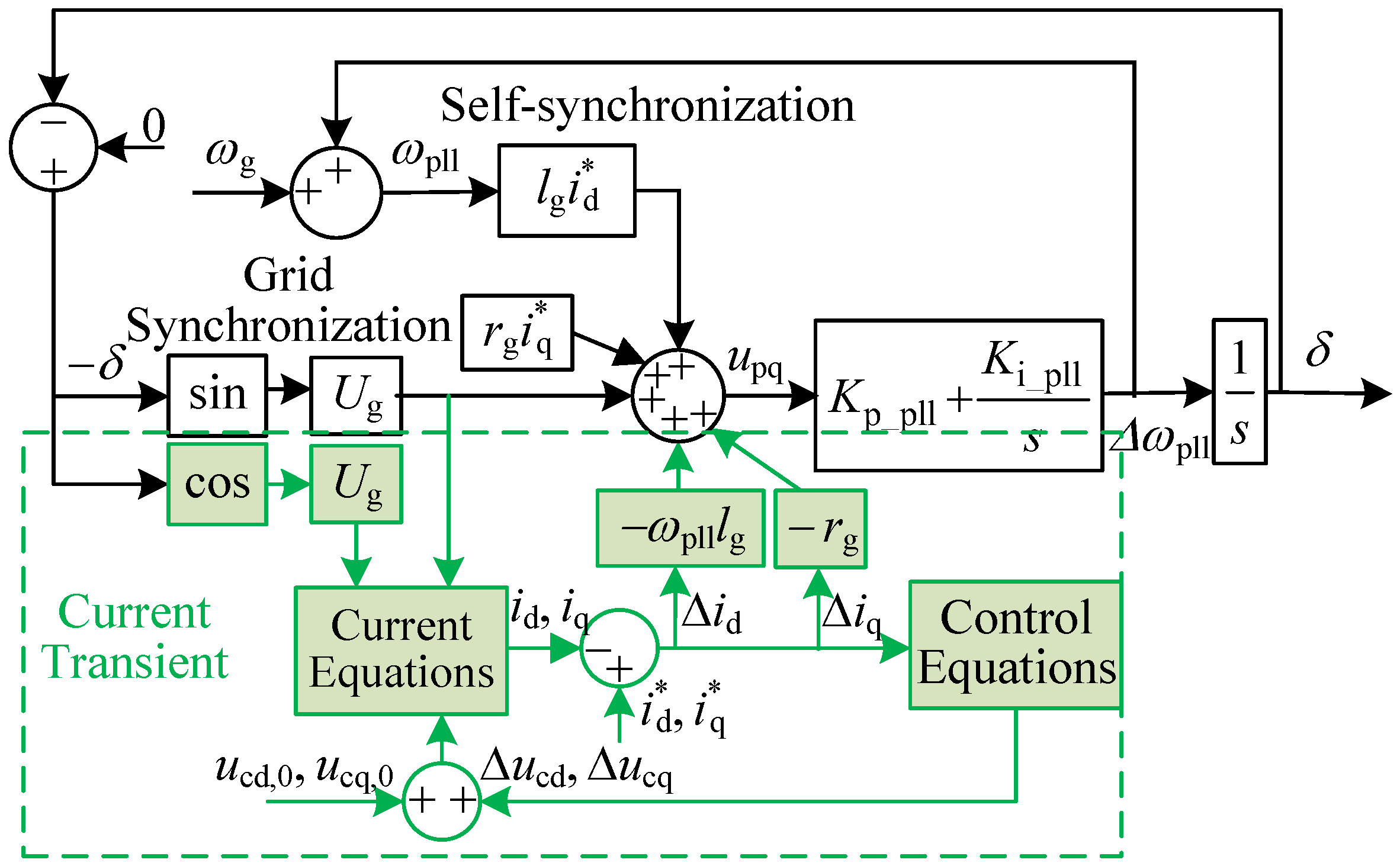
It can be observed from (2) that δ 0 [ 0 , 90 ] . At this moment, the GFL system is shown in the upper part of the black block diagram in Figure 2. Given that the current controller’s time constant is significantly shorter than the PLL’s, most existing studies approximate the injected current as constant and only focus on the PLL frequency deviation. This simplified approach assumes the filter inductance plays no role in synchronization stability.
In practice, the current control loop inevitably exhibits transient behavior during fault conditions. These transient currents produced during regulation cause fluctuations in the PCC voltage, which then impact the PLL’s response. Consequently, the phase output from the PLL affects how the injected grid current is calculated. This demonstrates a clear coupling between the PLL and the current control loop, meaning the influence of current transients on synchronization stability must not be overlooked. Taking into account the transient current deviations Δ i d and Δ i q , the q-axis component of the PCC voltage can be expressed as
u pq = U g sin ( δ ) + ( ω g + Δ ω pll ) l g ( i d * Δ i d ) + r g ( i q * Δ i q ) U g sin ( δ ) + ( ω g + Δ ω pll ) l g i d * + r g i q * ω g l g Δ i d r g Δ i q
where Δ ω pll = ω p ω g ω pll ω g denotes the PLL’s frequency deviation, Δ i d = i d * i d and Δ i q = i q * i q represent the differences between the reference values and instantaneous values of the GFL output current in the d and q axes, respectively. As shown in Figure 1, the GFL output current’s instantaneous magnitude is given by
i d + j i q = U c U g r g + j ω pll ( l g + l f )
From Equation (4), it’s clear that to get a handle on the GFL’s output current, you can tweak the VSC’s terminal voltage, U c , by using various control tactics. If we look at a PI control method that doesn’t involve voltage feedforward, the formula for adjusting the GFL’s terminal voltage is as follows.
Δ u cd = K p _ acc Δ i d + K i _ acc Δ i d d t + ω g l f Δ i q Δ u cq = K p _ acc Δ i q + K i _ acc Δ i q d t ω g l f Δ i d ,
where Δ u cd and Δ u cq represent the variations of the GFL terminal voltage, while K p _ acc and K i _ acc denote the proportional and integral gains of the voltage control loop’s PI compensator. Given the present transient conditions, the supplementary current control loop is illustrated within the dashed outline in the upper section of Figure 2. Based on the current and control equations provided—specifically (4) and (5)—it’s evident that the filter inductance has been incorporated into the GFL grid-connected system’s control loop. Consequently, the impact of this filter inductance on the system’s transient stability cannot be overlooked.

3. Analysis of Filter Inductance Impact on Transient Stability

This section establishes a theoretical framework to examine how filter inductance influences PLL frequency deviation across two distinct grid resistance scenarios—accounting for resistance and omitting it. The analysis extends a synchronous stability model that incorporates current transient, enabling a methodical evaluation of filter inductance’s role in power system synchronization stability.

3.1. Modeling of Filter Inductance Impact on Synchronization Stability

Based on (4), the current equation can be given by
i d = r g u cd U g cos δ + ω pll l f + l g u cq + U g sin δ ω pll 2 l f + l g 2 + r g 2 i q = r g u cq + U g sin δ ω pll l f + l g u cd U g cos δ ω pll 2 l f + l g 2 + r g 2
The terminal voltage of GFL can be expressed as
u cd = U g cos ( δ ) ω pl 1 l f + l g i q + r g i d u cq = U g sin ( δ ) + ω pl 1 l f + l g i d + r g i q
Assuming that the grid voltage in steady state is U g , 0 , as well as the PLL’s phase angle is δ 0 and the frequency is ω g . The voltage at VSC terminal and injected current into the grid are all considered as reference values, i.e., u cd , 0 = u cd * , u cq , 0 = u cq * , i d , 0 = i d * , i q , 0 = i q * . At this moment, the VSC terminal voltage conforms to
u cd , 0 = U g , 0 cos δ 0 ω g l f + l g i q * + r g i d * u cq , 0 = U g , 0 sin δ 0 + ω g l f + l g i d * + r g i q *
When the grid fault of voltage sag occurs, the grid voltage becomes U g + , and the VSC terminal voltages are u cd + and u cq + , and the injected currents into the grid are i d + , i q + , respectively. The phase angle and frequency of PLL are denoted as δ and ω pll , respectively. Since the converter is unable to respond instantaneously at the moment of the voltage, only the grid voltage and current experience changes, while the VSC terminal voltage, as well as the PLL phase angle and frequency remain unchanged. That is U g , 0 + = U g Δ U g , i d + = i d * Δ i d , i q + = i q * Δ i q , u cd + = u cd , 0 , u cq + = u cq , 0 , δ = δ 0 , ω pll = ω g . At this moment, the VSC terminal voltage can be given by
u cd , 0 + = U g , 0 cos ( δ ) ω pll l f + l g i q * Δ i q + r g i d * Δ i d u cq , 0 + = U g , 0 sin ( δ ) + ω pll l f + l g i d * Δ i d + r g i q * Δ i q
By combining (8) and (9), the following expression can be obtained
Δ i d = r g Δ U g cos δ 0 + ω g l f + l g Δ U g sin δ 0 ω g 2 l f + l g 2 + r g 2 Δ i q = ω g l f + l g Δ U g cos δ 0 r g Δ U g sin δ 0 ω g 2 l f + l g 2 + r g 2
Considering that the integrator in the PLL responds slowly at the instant of a fault, taking only the proportional part is sufficient to reflect the impact of filter inductance on the transient variation of the power angle; neglecting the integral part simplifies the model and facilitates analysis without obscuring the main physical mechanism [13,23]. As shown in Figure 2, the PLL frequency deviation is given by
Δ ω pll K p _ pll = ω pll l g i d * + U g sin δ 0 + r g i q * ω g l g Δ i d r g Δ i q
By substituting (2) and (10) into (11), Δ ω pll can be obtained as (12), The detailed mathematical derivation steps can be found in Equations (A1) and (A2) in Appendix A.1.
Δ ω pll = α 1 β 1
where
α 1 = Δ U g K p _ pll β 1 = ω g 2 l f + l g l g sin δ 0 + r g 2 sin δ 0 ω g 2 l f + l g 2 + r g 2 ω g l f + l g r g cos δ 0 ω g 2 l f + l g 2 + r g 2 + ω g l g r g cos δ 0 ω g 2 l f + l g 2 + r g 2
From (13), α 1 can be considered approximately constant with respect to the filter inductance l g , the variation of Δ ω pll is mainly determined by β 1 . Therefore, it can be concluded that the effect of filter inductance on the transient stability of the system can be determined by analyzing the monotonicity of β 1 with respect to the filter inductance. Let the independent variable be defined as l fg = l f + l g , where l fg > l g > 0 . Then, the transient stability strength analysis function f l fg is defined as
f l fg = ω g 2 sin δ 0 l fg 2 + α 2 l fg + β 2 ω g 2 l fg 2 + r g 2
where
α 2 = ω g 2 l g sin δ 0 ω g r g cos δ 0 β 2 = ω g l g r g cos δ 0
By differentiating (14), the following result is obtained as
d f d l fg = α 2 r g 2 α 2 ω g 2 l fg 2 2 β 2 ω g 2 + 2 ω g 2 r g 2 sin δ 0 l fg ω g 2 l fg 2 + r g 2 2
Defining the stability strength gradient function g l fg = α 2 ω g 2 l fg 2 2 ω g 2 r g 2 sin δ 0 + 2 β 2 ω g 2 l fg + α 2 r g 2 . It is only necessary to determine the sign of g l fg in order to obtain the variation pattern of the system’s transient stability strength with respect to changes in the filter inductance.

3.2. Impact of Filter Inductance on Synchronization Stability in Different Cases

According to above analyses, the critical point is to ensure the change of f l fg and g l fg with filter inductance. Through coefficient α 2 , the analysis can be divided into the following three cases.

3.2.1. Case of α 2 = 0

Combing (15) with α 2 = 0 , the following expression can be obtained.
tan δ 0 = r g ω g l g
where r g / ω g l g = μ is the ratio of grid resistance to grid reactance, which satisfies μ > 0 . That is, δ 0 = 90 , 0 . Consequently, β 2 > 0 .
Considering this case, f l fg and g l fg can be denoted as
f l fg = ω g 2 sin δ 0 l fg 2 + β 2 ω g 2 l fg 2 + r g 2 g l fg = 2 β 2 ω g 2 + 2 ω g 2 r g 2 sin δ 0 l fg
It can be seen that g l fg < 0 , f l fg < 0 . That is to say, f l fg is decreasing monotonically. Since f ( 0 ) > 0 , f l fg < 0 . Correspondingly, as l f increases, f l fg increases monotonically. As a result, the PLL frequency deviation increases, the power angle overshoot becomes larger, and the transient stability of GFL converter is weakened.

3.2.2. Case of α 2 > 0

Combining (15) with α 2 > 0 and r g / ω g l g > 0 , it can be obtained that tan δ 0 > μ . Consequently, β 2 > 0 . When α 2 > 0 , g l fg is a downward-opening quadratic function, and the value of function at the vertex is
y max = 4 α 2 2 ω g 2 r g 2 2 β 2 ω g 2 + 2 ω g 2 r g 2 sin δ 0 2 4 α 2 ω g 2 > 0
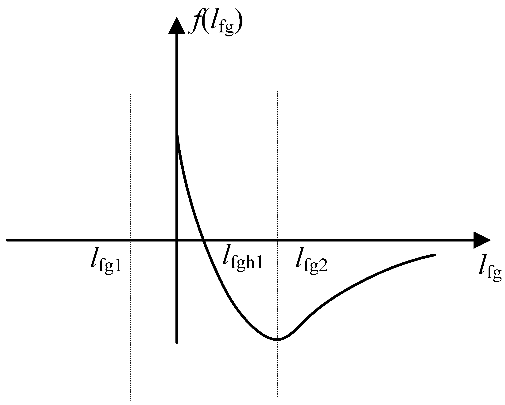
Therefore, g l fg has two zeros, namely l fg 1 > 0 , l fg 2 < 0 . When 0 < l fg < l fg 1 , g l fg > 0 , f l fg > 0 , f l fg is monotonically increasing. When l fg > l fg 1 , g l fg 0 , f l fg < 0 , f l fg is monotonically decreasing. By setting f l fg = 0 , it can be obtained that f l fg has two zeros, which are l fgh 1 > 0 , l fgh 2 < 0 . Since f ( 0 ) > 0 , the variation trend of f l fg can be described as Figure 3. The expressions of the zeros l fg 1 , 2 and l fgh 1 , 2 are given in Equations (A3) and (A4) in Appendix A.2.
Therefore, when 0 < l fg < l fg 1 , f l fg increases monotonically. When l fg 1 < l fg < l fgh 1 , f l fg decreases monotonically. When l fg > l fgh 1 , f l fg increases monotonically.

3.2.3. Case of α 2 < 0

Combing (15) with α 2 < 0 , it can be obtained that tan δ 0 < μ and β 2 > 0 . When α 2 < 0 , g l fg is an upward-opening quadratic function, and the value of the function at the vertex is
y max = 4 α 2 2 ω g 2 r g 2 2 β 2 ω g 2 + 2 ω g 2 r g 2 sin δ 0 2 4 α 2 ω g 2 < 0
At this time, y max < 0 and g l fg has two zeros, which are l fg 1 < 0 , l fg 2 > 0 , respectively. When 0 < l fg < l fg 2 , g l fg < 0 , f l fg < 0 , f l fg decreases monotonically. When l fg > l fg 2 , g l fg > 0 , and f l fg > 0 , f l fg increases monotonically. The expressions of the zeros l fg 1 , 2 are given in Equation (A5) in Appendix A.3.
(1) When 0 < tan δ 0 < μ and sin δ 0 > 0 , the two zeros of f l fg are l fgh 1 > 0 and l fgh 2 < 0 . In this case, the variation trend of f l fg can be described as Figure 4.
Therefore, when 0 < l fg < l fgh 1 , f l fg decreases monotonically; when l fgh 1 < l fg < l fg 2 , f l fg increases monotonically; when l fg > l fg 2 , f l fg again decreases monotonically.
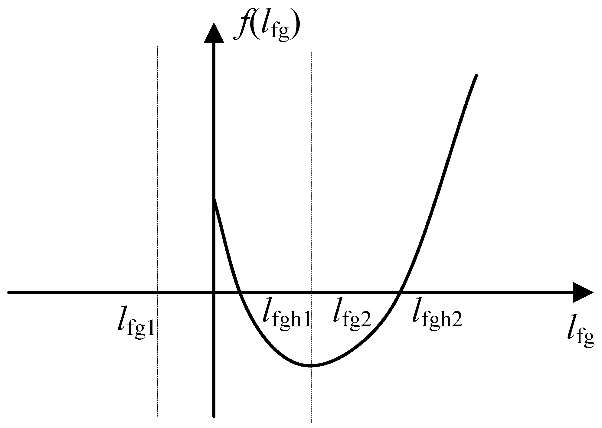
(2) When tan δ 0 < 0 and sin δ 0 < 0 , it follows from (14) that Δ > 0 , indicating that f l fg has two zeros. And it can be calculated that the two zeros satisfy l fgh 1 > 0 and l fgh 2 > 0 . At this time, the variation trend of f l fg can be described as Figure 5. The expressions of the zeros l fgh 1 , 2 are given in Equation (A6) in Appendix A.3.
Therefore, when 0 < l fg < l fgh 1 , f l fg decreases monotonically; when l fgh 1 < l fg < l fg 2 , f l fg increases monotonically; when l fg 2 < l fg < l fgh 2 , f l fg decreases monotonically and when l fg > l fgh 2 , f l fg increases monotonically. Based on the analysis in this section, the impact of filter inductance on the transient stability of the system under consideration of grid resistance can be summarized, as shown in Table 1.

4. Simulations and Validations

This section assesses how filter inductance affects synchronization stability and tests the findings against the proposed fourth-order synchronization stability model, with the key parameters listed in Table 2. To methodically explore how changes in filter inductance shape the stability of GFL grid-connected systems, we reduce the voltage of the source to simulate post-fault voltage sags, while assuming the grid impedance values are known. Time-domain simulations are conducted using MATLAB/Simulink.

4.1. Impact of Filter Inductance on Transient Stability

At t = 5 s, the grid voltage dips to 0.40 p.u. While keeping the grid inductance constant, the initial power angle δ 0 is close to zero. According to the impedance ratio analysis, the condition tan ( δ 0 ) < μ is generally satisfied. Therefore, after taking grid resistance into account, this study focuses on verifying scenarios where tan ( δ 0 ) < μ . To this end, as shown in Table 3, under the condition that tan ( δ 0 ) < μ , this study analyzes the power angle response curves under different filter inductances by varying r g .
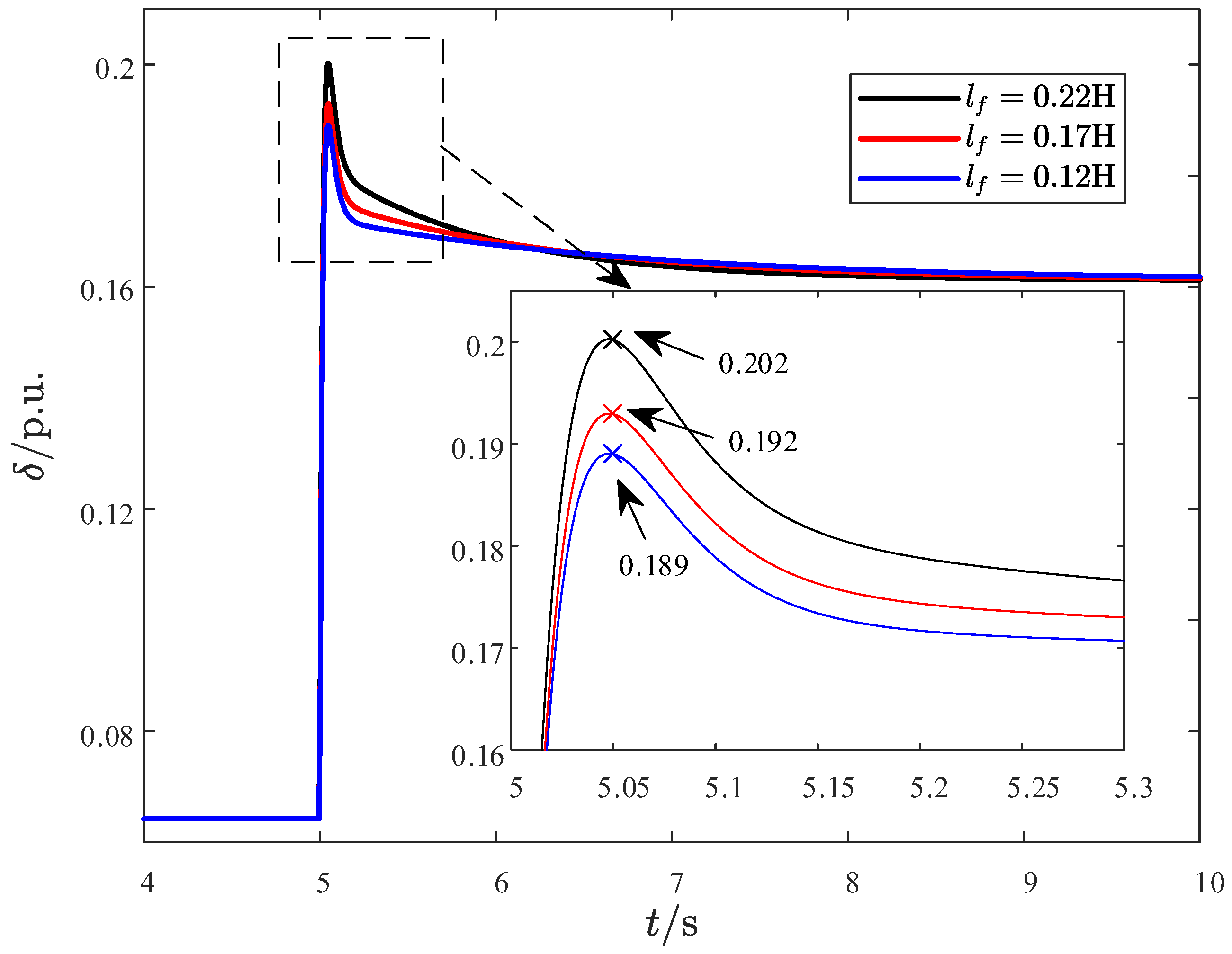
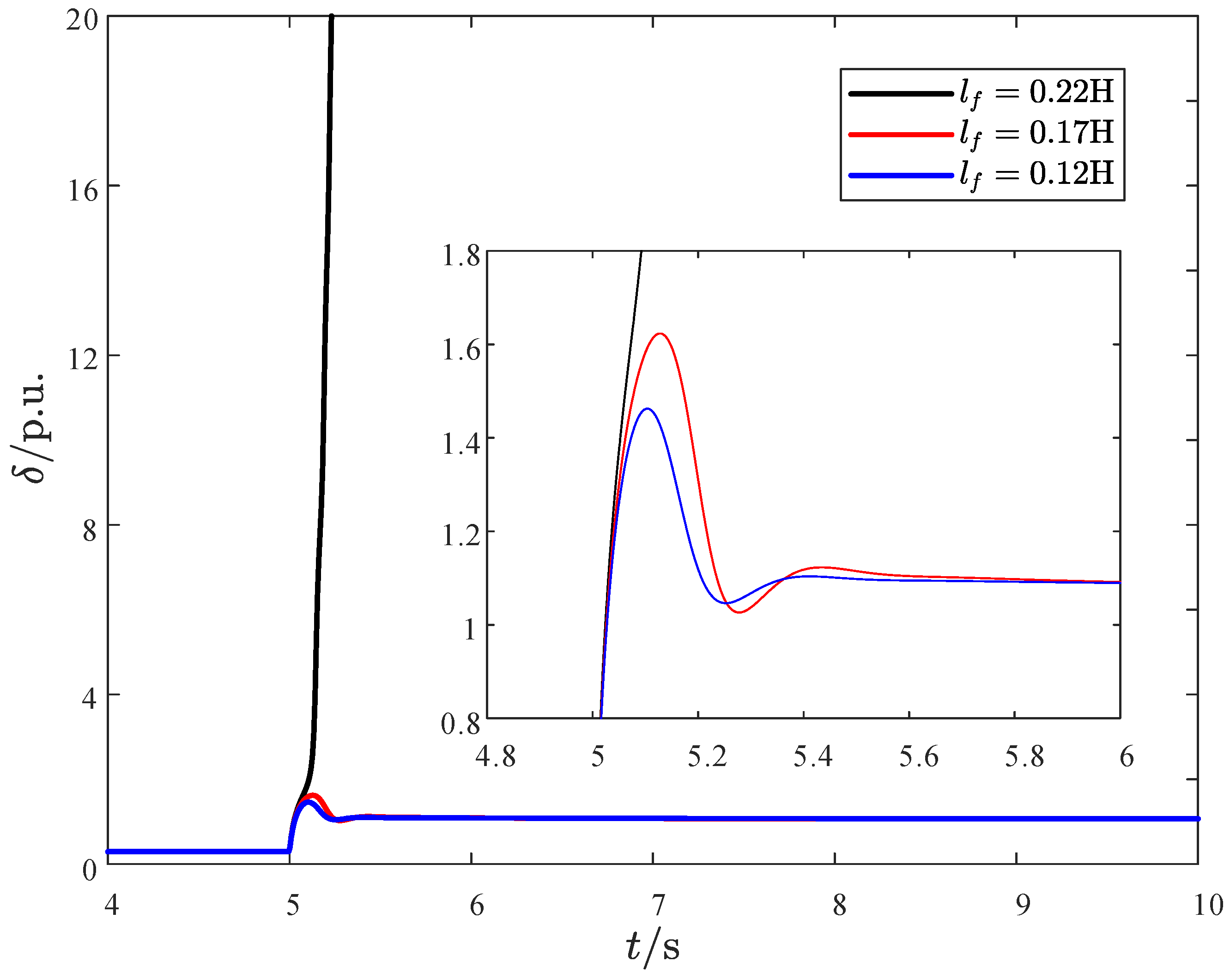
The power angle response curve of the GFL converter with r g = 30 and r g = 10 are given in Figure 6 and Figure 7, respectively. In Figure 6, the transient stability deteriorates with the increase of filter reactance. Compared with the power angle response in Figure 7, it indicates that the transient stability increases as the filter resistance increases. In addition, it is observed that improper settings of the filter inductance may even lead to system instability. The simulation results are consistent with the theoretical findings.
To further validate the transient stability support capacity of the system, a grid voltage dip to 0.30 p.u. is applied at t = 5 s. The power angle response curve of the GFL is shown in Figure 8.
As shown in Figure 8, when r g = 30 and the voltage dips to 0.30 p.u., the system remains stable with l f = 0.17 H , while it becomes unstable when l f = 0.22 H . This indicates that the system exhibits different fault critical voltages as l f varies, i.e., the transient stability support capability changes accordingly. In addition, in order to quantitatively assess how the filter inductance influences the system’s transient stability, we conducted a sensitivity analysis. The sensitivity analysis is formulated as follows
S = δ ( t 0 + Δ t ) δ ( t 0 ) Δ U
where t 0 denotes the time when the disturbance happens, Δ t is a very small time interval used to observe the change after the disturbance. And Δ U represents the voltage drop. The sensitivity at the instant of fault occurrence is shown in Table 4.
Table 4 clearly shows that increasing the filter inductance, decreasing the grid resistance, and deepening the voltage dip all significantly increase the system’s sensitivity during faults, thereby degrading its transient stability. As filter inductance grows, system inertia increases while the synchronizing power coefficient decreases, causing fluctuations in the power angle curve and reducing the critical voltage margin. Meanwhile, a larger l f weakens the damping of the current loop, making post-disturbance oscillations more easily amplified, thereby degrading transient stability. Therefore, the filter inductance significantly affects the transient stability of modern power systems cannot be neglected.

4.2. Impact of Control Parameters on Transient Stability

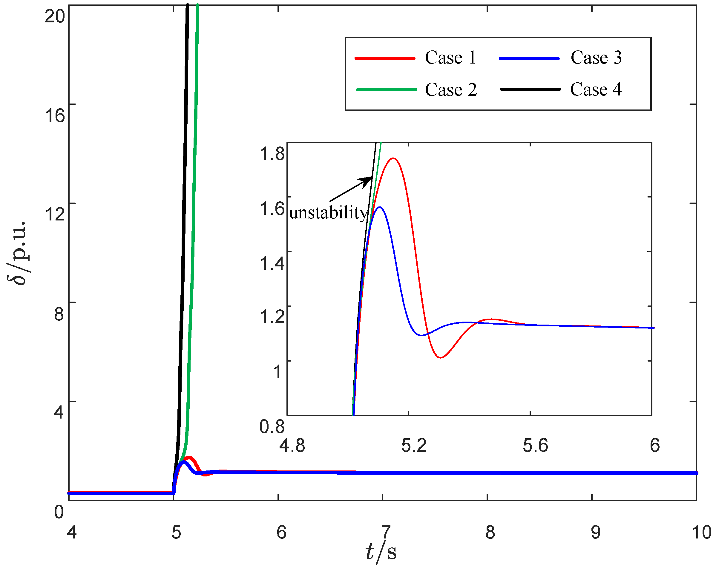
To evaluate the effect of coordinated tuning of control parameters, the PLL PI parameters ( K ppll and K ppll ) were adjusted to modify the controller settings, as detailed in Table 5. The system’s transient stability was then analyzed with rising filter inductance.
In Figure 9, the results show that optimizing the PLL PI parameters can partially mitigate the adverse effects caused by voltage dips. However, when the filter inductance lf becomes excessively large, although the rate of instability is somewhat alleviated, the system still tends to lose stability. This is consistent with the conclusions obtained in the previous section, demonstrating that controller retuning alone cannot fully eliminate the negative impact of an excessively large filter inductance.

4.3. Impact of Grid Resistance on Transient Stability

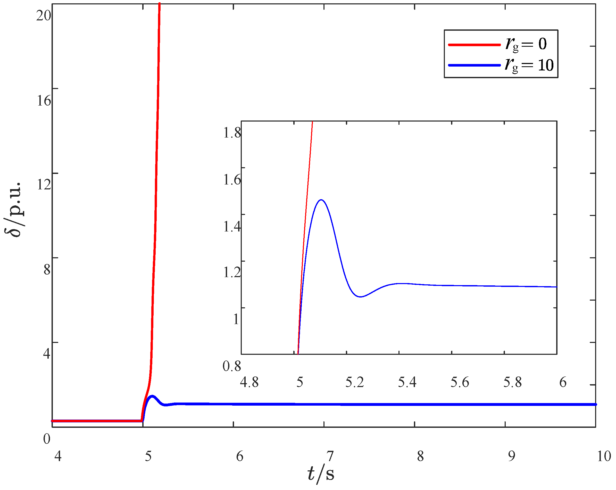
In our previous work [20], grid resistance was neglected; however, its impact in practical power systems cannot be ignored. Therefore, with other variables kept constant, the system’s transient stability was compared under two grid resistances, r g = 0 and r g = 10 , as shown in Figure 10.
From the comparative analysis in Figure 10, it can be seen that when the grid resistance is neglected, the system lacks sufficient damping, causing the power angle to continuously diverge after a fault and making the system prone to instability. In contrast, when the grid resistance is considered, the system damping is enhanced, the power angle oscillations decay rapidly, and the system can recover stability more quickly. This indicates that grid resistance plays a crucial role in enhancing system synchronization stability, suppressing oscillations caused by the filter inductance, and improving fault recovery capability; therefore, it should not be neglected in transient stability analysis.

4.4. Comparative Study Between the Conventional Full-Detail Model and the Model Considering Current Transients

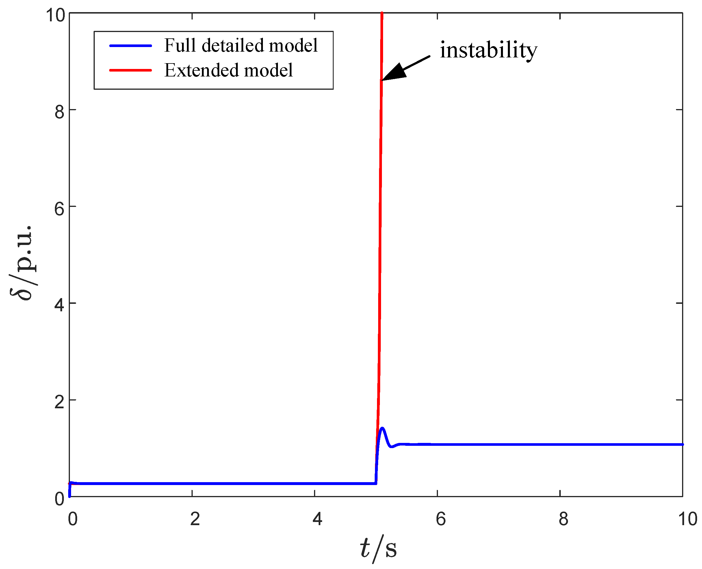
Since the above simulations were all conducted using the four-order extended model that considers current transients, a full-detail conventional model was also constructed for comparison with the commonly used GFL synchronization stability model that neglects current transients. The same control parameters and filter inductance values were applied to both models, and an identical grid voltage sag was imposed at t = 5 s to observe the power angle. The simulation results are shown in Figure 11.
As seen in Figure 11, when the filter inductance is increased, the power angle in the extended model exhibits larger overshoots and eventual loss of synchronism, while the conventional model without current transients remains stable under the same conditions. This comparison demonstrates that the extended model is able to capture the destabilizing effect of large filter inductance, highlighting the necessity and the accuracy of including current transient dynamics for an accurate assessment of GFL synchronization stability. These results provide strong evidence for the effectiveness and practical relevance of the proposed modeling approach.

5. Conclusions

Based on the improved synchronization stability model that includes current transients, this paper examines how filter inductance affects synchronization stability. A predictive expression for GFL frequency deviation incorporating filter inductance during faults is derived. The effect of filter inductance on GFL synchronization stability is then systematically investigated through two key metrics: power angle overshoot and critical fault voltage. During fault transients, it is necessary to quantitatively analyze the influence of the filter inductance on the overshoot of the PLL power angle curve in conjunction with the ratio of grid resistance to grid reactance under different operating conditions. Moreover, the critical fault voltage rises as filter inductance increases, which compromises the transient stability of the system. Thus, fine-tuning the filter inductance and the damping will enhance the synchronization stability of the system, improving both its synchronous response and fault tolerance. Future research will aim to extend the applicability of the proposed model to power systems with higher renewable energy penetration. In practical engineering scenarios, stronger interactions may exist among multiple converters as well as between converters and the grid, while grid harmonics, unbalanced faults, or alternative control strategies may introduce additional dynamic effects. To more comprehensively assess the impact of filter inductance on the transient stability of the system, future work will gradually incorporate these factors into the model, establishing a framework that more closely reflects power system conditions and providing a robust theoretical basis for the secure integration of renewable energy sources.

Author Contributions

Conceptualization, Q.M.; methodology, Q.M.; software, Q.M., J.Y. and Y.W.; validation, Q.M., J.Y. and Y.W.; formal analysis, Q.M., J.Y. and Y.W.; investigation, Q.M., J.Y. and Y.W.; resources, S.S. and J.X.; data curation, Q.M. and Y.W.; writing—original draft preparation, J.Y. and Y.W.; writing—review and editing, Q.M.; visualization, Q.M.; supervision, S.S. and J.X.; project administration, S.S. and J.X.; funding acquisition, S.S. and J.X. All authors have read and agreed to the published version of the manuscript.

Funding

This work is funded by National Key R&D Program of China (Key Techniques of Adaptive Grid Integration and Active Synchronization for Extremely High Penetration Distributed Photovoltaic Power Generation, 2022YFB2402900). Supporting project, project number: 52060023001T.

Institutional Review Board Statement

Not applicable.

Informed Consent Statement

Not applicable.

Data Availability Statement

The original contributions presented in this study are included in the article. Further inquiries can be directed to the corresponding author.

Acknowledgments

During the preparation of this manuscript, the authors used Matlab/Simulink for the purposes of verifying the correctness of the theoretical analysis. The authors have reviewed and edited the output and take full responsibility for the content of this publication.

Conflicts of Interest

Author Shumin Sun and Jiawei Xing was employed by the company Electric Power Research Institute, State Grid Shandong Electric Power Co., Ltd. The remaining authors declare that the research was conducted in the absence of any commercial or financial relationships that could be construed as a potential conflict of interest.

Abbreviations

The following abbreviations are used in this manuscript:
GFLGrid-following
PLLPhase-locked loop
PCCPoint of common coupling
VSCVoltage source converter
PWMPulse width modulation
KCLKirchhoff’s current law

Appendix A. Mathematical Formulas

Appendix A.1. Supplementary Mathematical Derivation Steps

As ω pll = ω g , substituting (2) into (11), Δ ω pll can be obtained as
Δ ω pll = K p _ pll ω pll l g i d * + U g sin ( δ 0 ) + r g i q * ω g l g Δ i d r g Δ i q = K p _ pll ω pll l g i d * r g i q * ω g l g i d * + r g i q * ω g l g Δ i d r g Δ i q = K p _ p l l ω g l g Δ i d r g Δ i q
Then, by substituting (10) into (A1), Δ ω pll can be derived as
Δ ω pll = Δ U g K p _ pll [ ω g l g r g cos δ 0 + ω g ( l f + l g ) sin ( δ 0 ) ω g 2 ( l f + l g ) 2 + r g 2 r g ω g ( l f + l g ) cos δ 0 r g sin ( δ 0 ) ω g 2 ( l f + l g ) 2 + r g 2 ]

Appendix A.2. Supplementary Mathematical Derivation Steps When α 2 >0

l fg 1 , 2 = 2 β 2 ω g 2 + 2 ω g 2 r g 2 sin δ 0 2 α 2 ω g 2 < 0 ± 2 β 2 ω g 2 + 2 ω g 2 r g 2 sin δ 0 2 + 4 α 2 2 ω g 2 r g 2 2 α 2 ω g 2 < 0
l fghl , h 2 = α 2 ± α 2 2 + 4 β 2 ω g 2 sin δ 0 2 ω g 2 sin δ 0 < 0

Appendix A.3. Supplementary Mathematical Derivation Steps When α 2 <0

l fg 1 , 2 = 2 β 2 ω g 2 + 2 ω g 2 r g 2 sin δ 0 2 α 2 ω g 2 < 0 ± 2 β 2 ω g 2 + 2 ω g 2 r g 2 sin δ 0 2 + 4 α 2 2 ω g 2 r g 2 2 α 2 ω g 2 > 0
l fgh 1 , h 2 = α 2 ± α 2 2 + 4 β 2 ω g 2 sin δ 0 2 ω g 2 sin δ 0 > 0

References

  1. Wang, G.; Fu, L.; Hu, Q.; Liu, C.; Ma, Y. Transient Synchronization Stability of Grid-Forming Converter During Grid Fault Considering Transient Switched Operation Mode. IEEE Trans. Sustain. Energy 2023, 14, 1504–1515. [Google Scholar] [CrossRef]
  2. Li, B.; Wang, Y. Enhanced Low-Voltage Ride-Through Scheme for Grid-Forming Converters Considering Current Limitation and Transient Stability Simultaneously. Sustainability 2025, 17, 1428. [Google Scholar] [CrossRef]
  3. Li, Y.; Xia, Y.; Ni, Y.; Peng, Y.; Feng, Q. Transient Stability Analysis for Grid-Forming VSCs Based on Nonlinear Decoupling Method. Sustainability 2023, 15, 11981. [Google Scholar] [CrossRef]
  4. Wang, Z.; Guo, L.; Li, X.; Wang, Z.; Zang, X.; Zhu, J.; Zhou, X.; Wang, C. Transient Synchronization Stability of Grid-Tied Multi-VSCs System Considering Nonlinear Damping and Transient Interactions. IEEE Trans. Power Electron. 2024, 39, 16775–16791. [Google Scholar] [CrossRef]
  5. Rigo, P.D.; Siluk, J.C.M.; Lacerda, D.P.; Spellmeier, J.P. Competitive Business Model of Photovoltaic Solar Energy Installers in Brazil. Renew. Energy 2022, 181, 39–50. [Google Scholar] [CrossRef]
  6. Liu, C.C.; Yang, J.; Tse, C.K.; Huang, M. Transient Synchronization Stability of Grid-Following Converters Considering Nonideal Current Loop. IEEE Trans. Power Electron. 2023, 38, 13757–13769. [Google Scholar] [CrossRef]
  7. Ali, Z.; Christofides, N.; Hadjidemetriou, L.; Kyriakides, E.; Yang, Y.; Blaabjerg, F. Three-Phase Phase-Locked Loop Synchronization Algorithms for Grid-Connected Renewable Energy Systems: A Review. Renew. Sustain. Energy Rev. 2018, 90, 434–452. [Google Scholar] [CrossRef]
  8. Zarei, S.F.; Mokhtari, H.; Ghasemi, M.A.; Peyghami, S.; Davari, P.; Blaabjerg, F. Control of Grid-Following Inverters Under Unbalanced Grid Conditions. IEEE Trans. Energy Convers. 2020, 35, 184–192. [Google Scholar] [CrossRef]
  9. Elkhidir, L.; Khan, K.; Al-Muhaini, M.; Khalid, M. Enhancing Transient Response and Voltage Stability of Renewable Integrated Microgrids. Sustainability 2022, 14, 3710. [Google Scholar] [CrossRef]
  10. Chen, J.; Liu, M.; Geng, H.; O’Donnell, T.; Milano, F. Impact of PLL Frequency Limiter on Synchronization Stability of Grid Feeding Converter. IEEE Trans. Power Syst. 2022, 37, 2487–2490. [Google Scholar] [CrossRef]
  11. Yang, J.; Tse, C.K.; Huang, M.; Liu, D. Bifurcations of Grid-Following Rectifiers and Routes to Voltage Instability in Weak AC Grids. IEEE Trans. Power Syst. 2023, 38, 1702–1713. [Google Scholar] [CrossRef]
  12. Yang, S.; Ma, R.; Wen, J.; Cheng, S. Equivalent circuit model of grid-forming-converter based power grids: Visualizing control loop interactions on synchronization stability. Int. J. Electr. Power Energy Syst. 2025, 168, 110692. [Google Scholar] [CrossRef]
  13. Wang, Y.; Ruan, L.; Yang, M.; Xiao, X.; Chen, S.; Gomis-Bellmunt, O. Control interaction analysis of hybrid system with grid-following and grid-forming inverters based on admittance decomposition. Int. J. Electr. Power Energy Syst. 2024, 162, 110267. [Google Scholar] [CrossRef]
  14. He, Y.; Xiang, W.; Meng, P.; Wen, J. Investigation on grid-following and grid-forming control schemes of cascaded hybrid converter for wind power integrated with weak grids. Int. J. Electr. Power Energy Syst. 2024, 155, 109524. [Google Scholar] [CrossRef]
  15. Hatziargyriou, N.; Milanovic, J.; Rahmann, C.; Ajjarapu, V.; Canizares, C.; Erlich, I.; Hill, D.; Hiskens, I.; Kamwa, I.; Pal, B.; et al. Definition and Classification of Power System Stability—Revisited & Extended. IEEE Trans. Power Syst. 2021, 36, 3271–3281. [Google Scholar] [CrossRef]
  16. Chen, J.; Liu, M.; O’Donnell, T.; Milano, F. Impact of Current Transients on the Synchronization Stability Assessment of Grid-Feeding Converters. IEEE Trans. Power Syst. 2020, 35, 4131–4134. [Google Scholar] [CrossRef]
  17. Lin, X.; Peng, J.C.-H.; Macii, D.; Petri, D.; Yu, J.; Wen, H. Frequency-domain small-signal stability analysis methods for grid-following converters systems—An overview. Renew. Sustain. Energy Rev. 2025, 211, 115283. [Google Scholar] [CrossRef]
  18. Tian, X.; Zhang, Y.; Xu, Y.; Zheng, L.; Zhang, L.; Yuan, Z. Transient synchronous stability modeling and comparative analysis of grid-following and grid-forming new energy power sources. Electronics 2024, 13, 3308. [Google Scholar] [CrossRef]
  19. Agbemuko, A.J.; Domínguez-García, J.L.; Gomis-Bellmunt, O.; Harnefors, L. Passivity-Based Analysis and Performance Enhancement of a Vector Controlled VSC Connected to a Weak AC Grid. IEEE Trans. Power Deliv. 2021, 36, 156–167. [Google Scholar] [CrossRef]
  20. Tian, H.; Zhang, Z.; Liu, W.; Wu, C.; Wu, Y. Influence of Filter Inductance on Synchronization Stability of Grid-Connected Converter. In Proceedings of the 2023 International Conference on Power System Technology (PowerCon), Wuhan, China, 21–23 November 2023; pp. 1–5. [Google Scholar] [CrossRef]
  21. Si, W.; Fang, J. Transient Stability Improvement of Grid-Forming Converters Through Voltage Amplitude Regulation and Reactive Power Injection. IEEE Trans. Power Electron. 2023, 38, 12116–12125. [Google Scholar] [CrossRef]
  22. Liu, Y.; Zhu, L.; Xu, X.; Li, D.; Liang, Z.; Ye, N. Transient Synchronization Stability in Grid-Following Converters: Mechanistic Insights and Technological Prospects—A Review. Energies 2025, 18, 1975. [Google Scholar] [CrossRef]
  23. Li, Y.; Fu, L.; Li, Q.; Wang, W.; Jia, Y.; Dong, Z.Y. Small-signal modelling and stability analysis of grid-following and grid-forming inverters dominated power system. Glob. Energy Interconnect. 2023, 6, 363–374. [Google Scholar] [CrossRef]
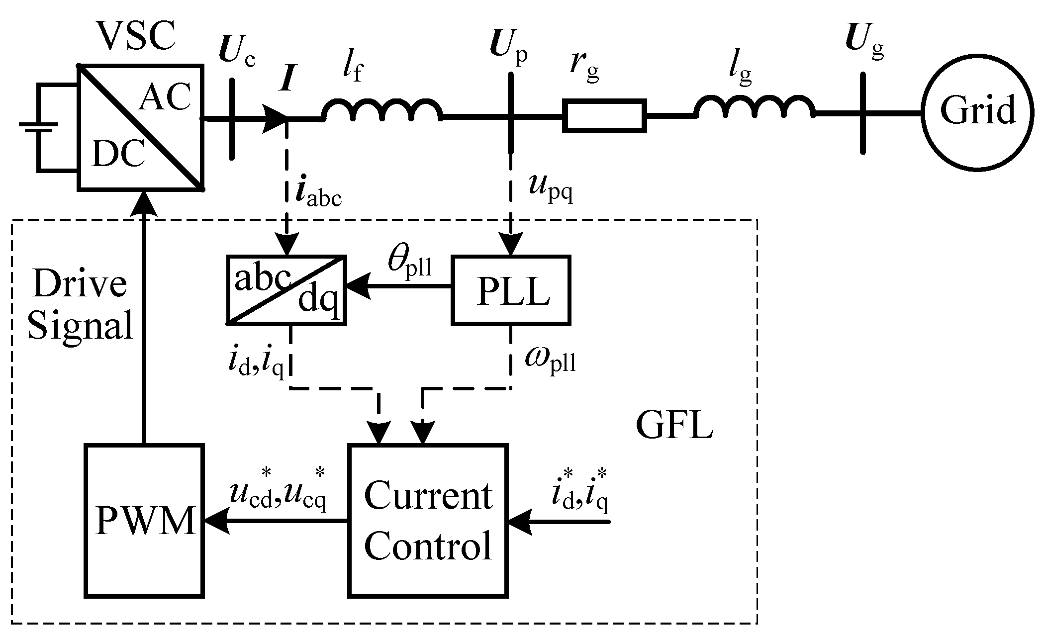
Figure 1. Diagram illustrating a grid-connected system with VSC-based GFL converter.
Sustainability 17 08634 g001
Figure 2. Control block diagram of the GFL converter.
Sustainability 17 08634 g002
Figure 3. Variation of transient stability analysis function under condition of α 2 > 0 .
Sustainability 17 08634 g003
Figure 4. Variation of transient stability analysis function under condition of α 2 < 0 .
Sustainability 17 08634 g004
Figure 5. Variation of transient stability analysis function under condition of tan ( δ 0 ) < 0 .
Sustainability 17 08634 g005
Figure 6. The power angle response curve of the GFL converter ( r g = 30   Ω , voltage dip 0.3 p . u . ).
Sustainability 17 08634 g006
Figure 7. The power angle response curve of the GFL converter ( r g = 10 Ω , voltage dip 0.3 p . u . ).
Sustainability 17 08634 g007
Figure 8. The power angle response curve of the GFL converter ( r g = 10 Ω , voltage dip 0.33 p . u . ).
Sustainability 17 08634 g008
Figure 9. The power angle response curve under different PLL parameters.
Sustainability 17 08634 g009
Figure 10. The power response curve of the GFL converter under different r g .
Sustainability 17 08634 g010
Figure 11. The power angle response curve of the GFL converter under different models.
Sustainability 17 08634 g011
Table 1. Summarization for influence of filter inductance on transient stability.
Classification of SituationsFilter Inductor VariationTransient Stability Variation
tan ( δ 0 ) = μ l f
tan ( δ 0 ) > μ l f 0 < l fg < l fg 1 , ↓
l fg 1 < l fg < l fgh 1 , ↑
l fg > l fgh 1 , ↓
0 < tan ( δ 0 ) < μ l f 0 < l fg < l fgh 1 , ↑
l fgh 1 < l fg < l fg 2 , ↓
l fg > l fg 2 , ↑
tan ( δ 0 ) < 0 l f 0 < l fg < l fgh 1 , ↑
l fgh 1 < l fg < l fg 2 , ↓
l fg 2 < l fg < l fgh 2 , ↑
l fg > l fgh 2 , ↓
Table 2. Key system parameters.
ParameterActual ValuePer-Unit Value
Rated capacity S n /MW1-
Rated voltage U n /kV10-
Rated frequency f n /Hz50-
Line inductance l g /H0.10.3
d-axis current command value i d * /A81.651.00
q-axis current command value i q * /A−40.82−0.50
Current loop integral coefficient K iacc 2433.004.87
PLL proportional coefficient K ppll 0.022180.000
PLL integral coefficient K ipll 0.3923200.000
Table 3. Grid resistance-inclusive case study.
Simulation Example l fg 1 l fg 2 l fgh 1 l fgh 2 l fg
r g = 30 0.04820.57370.10.28700.12 + 0.1
0.17 + 0.1
0.22 + 0.1
r g = 10 0.01300.13000.08410.11620.22 + 0.1
0.32 + 0.1
0.42 + 0.1
Table 4. Sensitivities of power angle at the fault instant.
r g Voltage Drop L f Sensitivity
300.30.2222.1744
300.30.1721.5134
300.30.1221.1826
100.30.2242.8528
100.30.1732.7740
100.30.1229.8500
100.330.2246.7631
100.330.1735.0317
100.330.1232.0640
Table 5. PLL PI parameter settings under varying filter inductance.
Case L f K ppll K ppll Stability
10.17 H0.0220.392stable
20.22 H0.0220.392unstable
30.17 H0.030.5stable
40.22 H0.030.5unstable
Disclaimer/Publisher’s Note: The statements, opinions and data contained in all publications are solely those of the individual author(s) and contributor(s) and not of MDPI and/or the editor(s). MDPI and/or the editor(s) disclaim responsibility for any injury to people or property resulting from any ideas, methods, instructions or products referred to in the content.