Article

Environmental Impact of Building Drainage Systems: Analysis of Embodied Carbon Emissions in Terms of Code-Based Design

School of Energy, Geoscience, Infrastructure, and Society (EGIS), Heriot-Watt University, Edinburgh EH14 4AS, UK
*
Author to whom correspondence should be addressed.
Sustainability 2025, 17(18), 8207; https://doi.org/10.3390/su17188207
Submission received: 31 July 2025 / Revised: 2 September 2025 / Accepted: 8 September 2025 / Published: 11 September 2025
(This article belongs to the Topic Sustainable Building Materials)

Abstract

Reducing carbon emissions in buildings requires a holistic approach that extends beyond structural materials and looks at the services within, such as Building Drainage Systems (BDS). However, limited scientific research has addressed the environmental impacts of BDS, and, to date, no studies have systematically analysed embodied carbon emissions from a design code perspective. This study evaluates the embodied carbon emissions of BDS based on calculations from four major international design codes, BS EN 12056 (Europe), IPC and UPC (USA), and AS/NZS 3500 (Australia/New Zealand), using polyvinyl chloride (PVC) pipework. System configurations recommended in the design codes, such as primary ventilation and secondary ventilation systems, were evaluated as well as a fully active system incorporating Air Admittance Valves (AAVs) and Positive Pressure Relief Devices (PPRDs) across a range of building sizes from 10 to 100 storeys. The findings reveal substantial differences in recommended pipe sizes among the codes, directly impacting total pipework material use and, in turn, the embodied carbon emissions. A life cycle assessment (LCA) of PVC pipework demonstrates that the design recommendations in the European code generally lead to lower embodied carbon emissions, while the IPC and UPCs result in significantly higher emissions, with the AS/NZS code falling in between. In contrast, the use of a fully active drainage system was shown to reduce embodied carbon emissions by up to 73% depending on the building size and the design code applied. As the sustainability of buildings and systems becomes more and more vital, the findings of this paper provide the foundations for integrating the sustainability metrics of BDS into design codes. This will provide practical guidance for engineers and regulators on how carbon savings in BDS design and construction can be achieved.

1. Introduction

With increasing awareness of sustainability in the built environment, there has been significant focus on structural and envelope materials of buildings [1]. However, relatively limited attention has been given to services within the building [2], despite their critical role in providing functionality and occupant comfort. Building services contribute notably to embodied carbon, particularly in renovation projects, where ageing systems require frequent maintenance and replacement [3]. Life Cycle Assessment (LCA) has shown that this sector considerably influences global energy, resource consumption, and waste generation, contributing approximately 37% of global CO2 emissions [4,5,6,7,8]. This significant impact has prompted more in-depth research on building services components, particularly mechanical, electrical, and plumbing (MEP) systems [9]. In addition, material selection and system configuration in building services can strongly affect carbon emissions and energy consumption [10,11]. A recent study by Nguyen et al. [12] on high-density polyethylene (HDPE) pipe alternatives demonstrated that material choice and durability strongly influence life cycle outcomes, with recycled and bio-based HDPE achieving lower greenhouse gas emissions than pristine HDPE, although trade-offs with cost and service life remain. A review study on pipeline materials also found that the usage phase is often the dominant contributor to global warming potential, particularly for carbon steel pipes due to friction losses and energy-intensive production processes. In contrast, HDPE and concrete pipes performed better, with transport impacts largely dependent on material weight, and installation methods such as trenchless horizontal directional drilling and conventional open-cut techniques [13]. Pipe materials may also differ in terms of recycling potential. Istrate et al. [14] showed that incorporating recycled HDPE into pipe-grade resins can reduce environmental impacts by up to 80% compared to virgin HDPE when high-purity waste streams are used. Furthermore, a comparative LCA of water and wastewater pipes by Du et al. [15] demonstrated that pipe diameter strongly influences lifetime global warming potential, with larger diameters increasing embodied impacts from material production and installation, while smaller diameters increase operational impacts from pumping energy. This suggests that the optimum diameters for sustainable pipe systems closely align with those determined by balancing technical design criteria and sustainability outcomes.
In addition to sustainability, building drainage systems (BDS) play a vital role in ensuring a safe indoor environment by preventing the cross-contamination of pathogens and viruses within buildings [16,17]. This occurs when system failures lead to trap seal depletion, allowing sewer gases to enter indoor spaces [18]. Thus, inappropriate BDS design can lead to the spread of diseases such as SARS and COVID-19 [19,20,21], posing serious risks to public health. Therefore, the accurate design of BDS is crucial to ensuring systems that are safe, efficient, and sustainable. The process of designing BDS involves determining system configurations and pipe sizes based on anticipated wastewater discharge loading. These calculations are specified in national design codes which vary from country to country. Despite the importance of BDS, there is no uniform global design code or consistent method for accurately estimating wastewater discharge loading from appliances and associated pipe sizing. As buildings increase in size and complexity, appliance usage patterns become more diverse and dynamic, making accurate pipe sizing more complex and critical. This challenge is particularly evident in high-rise and multi-storey buildings, which have become more common in recent decades as a result of rapid urbanisation and the growth of emerging economies [22]. It has also been shown that the mechanisms of solid transport in horizontal drains are directly influenced by the diameter of the drain pipe and, therefore, there are implications for increasing blockages in the system due to incorrectly sized pipes [23]. Furthermore, the sustainability impact of BDS is little understood and seldom considered in practice, and current design codes do not provide information to the designer about the sustainability impact of their design. This is, in part, due to an overall lack of research and literature on the environmental impacts of BDS. To begin to address this gap, this paper quantifies the embodied carbon associated with PVC pipework used for BDS for a range of buildings from 10 to 100 storeys designed using four different international design codes: (i) BS EN 12056 [24]; (ii) AS/NZS 3500 [25]; (iii) UPC [26]; and (iv) IPC [27]. The study compares recommended system configurations and pipework sizing for each international design code before quantifying the associated embodied carbon. By revealing how design choices influence the system’s overall carbon footprint, the study provides a vital insight for advancing sustainable BDS practices and supporting the transition toward net-zero targets.

2. Embodied Carbon Emissions of BDS

Sustainability in the built environment has become a central priority in response to the growing urgency of climate change and the need to reduce environmental impacts across all construction stages. Building services and their components contribute significantly to embodied carbon due to their extensive use of plastic and metal materials throughout their life cycles [3,4,5,6]. For instance, Itanola et al. [7] showed that MEP systems in buildings can contribute up to 27% of embodied carbon in new constructions, rising to as much as 75% in renovation projects. This impact tends to increase over time due to their relatively short service lifespan. As in-depth assessments of building materials provide critical insights to guide design decisions towards more sustainable outcomes [28], the environmental impacts of BDS should not be underestimated, especially in high-rise buildings where drainage pipe lengths increase considerably with building height. Assessing and minimising embodied carbon in drainage systems, therefore, is crucial for achieving low-carbon building designs and meeting sustainability targets.

2.1. Materials Used in BDS

A variety of materials are used for pipework in BDS, including polyvinyl chloride (PVC), Polyethylene (PE), Polypropylene (PP), high-density polyethylene (HDPE), cast iron, ductile iron and galvanised steel [15]. Material selection is influenced by factors such as mechanical performance, chemical resistance, durability, cost-effectiveness, ease of installation, and maintenance requirements. Among these, PVC is currently the predominant material used in modern building drainage systems, particularly the unplasticised form (uPVC).
Since its industrial introduction in the early 1930s, PVC has increasingly dominated the plastic piping sector due to its cost-effectiveness, light weight, excellent resistance to corrosion, ease of handling, and installation efficiency [29]. PVC is extensively used in gravity-fed and unpressurised drainage applications, including wastewater pipes, soil stacks, downpipes, guttering, and rainwater systems [30]. Its popularity is further justified by low maintenance requirements, strong mechanical properties, and compatibility with standard fittings, facilitating streamlined installation and future modifications. From a sustainability perspective, PVC offers a notably lower carbon footprint across its life cycle, from raw material extraction through to end-of-life disposal compared to other materials [31]. A recent LCA by Xiong et al. [10] compared different pipe materials for water supply and drainage systems and found that using PVC reduced environmental impacts by up to 91% compared to copper and by 86% compared to galvanised steel and cast iron. This study highlighted that, in addition to system performance and initial cost, it is essential to account for differences in resource consumption, energy demand, and pollutant emissions over the entire life cycle of pipe systems. Increased recycling of PVC is known to further reduce its overall carbon emissions footprint, enhancing its environmental performance across the product life cycle [32]. Therefore, this study specifically investigates PVC pipework in BDS, focusing on evaluating its embodied carbon emissions. Table 1 summarises key physical and thermal properties of PVC, demonstrating characteristics beneficial for drainage applications.

2.2. Boundary Conditions and Life Cycle Stages

Evaluating the environmental impact of BDS requires a clear definition of the boundaries that reflect the life cycle stages contributing to the embodied carbon emissions. In LCA, embodied carbon focuses on the total greenhouse gas emissions associated with raw material extraction, manufacturing, transportation, installation, maintenance and end-of-life disposal or recycling of materials. The standard BS EN 15804, BS EN 15978, and CIBSE TM65 guide [33,34,35] provides a detailed breakdown of these life cycle stages, which are illustrated in Figure 1. Typically, system boundaries in LCA studies follow three principal approaches: (i) Cradle-to-Gate: covers the emissions from raw material extraction (cradle) up to the point the product leaves the factory (gate), including stages A1 to A3; (ii) Cradle-to-Site: extends cradle-to-gate by including transport to the construction site (A4) and installation (A5); and (iii) Cradle-to-Grave: the most comprehensive, this includes the full life cycle up to disposal or recycling, incorporating use, maintenance, and end-of-life stages (B1–C4), plus any reuse or recycling benefits (D1).
Accurately quantifying cradle-to-grave emissions can be challenging, especially for internal drainage components where use phases and end-of-life scenarios can vary significantly. Assessments of wastewater piping systems have also shown that the production phase accounts for the largest share of environmental impacts across all pipe materials, with fossil fuel depletion being particularly significant [31]. A comparative LCA of 180 MEP products by Harnot and George [35] has shown that the product stage (A1–A3) contributes approximately 92% of embodied carbon emissions. Given the comparative nature of this study, which assesses the relative impact of using PVC in different system configurations and excludes operational energy usage, the cradle-to-gate boundary (A1–A3) is adopted. Furthermore, the incremental difference between cradle-to-gate and cradle-to-site impacts is minimal, as pipes of varying sizes can be efficiently nested for transport, reducing transport-related impacts. Thus, focusing on the cradle-to-gate stage ensures consistency and practical relevance, highlighting significant embodied carbon contributions in the early phases of production.

3. Methodology

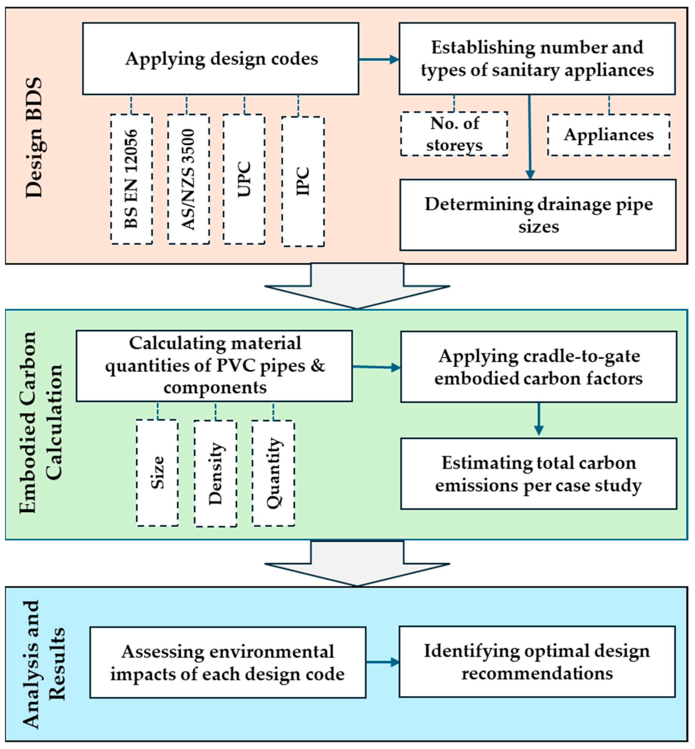
To evaluate the embodied carbon emissions of BDS designed under different international design codes, this study applies four major international codes across a range of building sizes from 10 to 100 storeys. The recommended system configurations and pipework sizing were derived from each code. A fully active system (incorporating Air Admittance Valves (AAVs) and Positive Pressure Relief Devices (PPRDs) was also derived for each building size. Material quantities were calculated and then converted into embodied carbon values using a cradle-to-gate life cycle assessment. This approach enables a direct comparison of how varying code recommendations influence the carbon footprint of BDS across building heights. The overall research process is summarised in Figure 2, which outlines the input parameters, analysis steps, and comparative assessment stages. The details of these steps are provided in the following subsections.

3.1. Design Codes for BDS

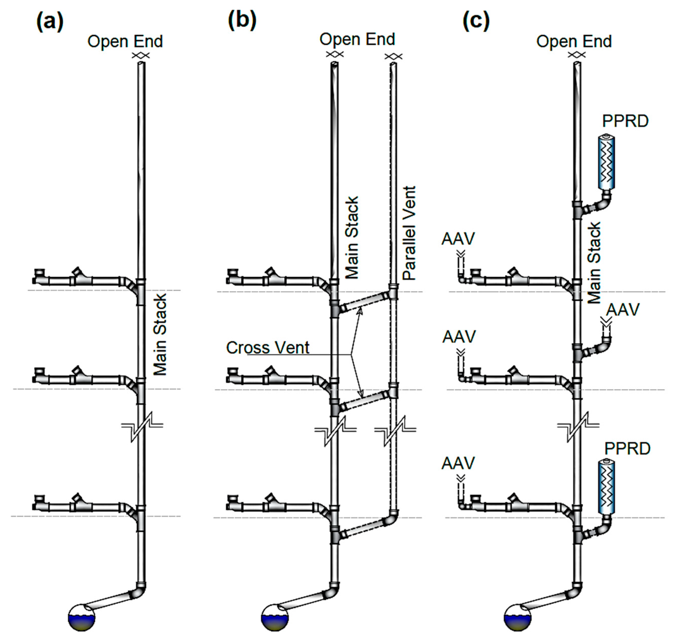
Most design codes use the “fixture unit” concept in the design of both water and drainage systems. This approach originated from the 1920s to 1940s, when the subject was first scientifically investigated by Dr. Roy B. Hunter in the USA. This method involves assigning fixture unit weights to plumbing appliances, which are then converted into equivalent gallons per minute based on usage probability [36]. This method has been fundamental in plumbing design since its inception. However, many of the factors used in developing the Hunter approach have changed over time, including water usage patterns, the efficiency of sanitary appliances and modern building designs. There is also evidence of limitations when current design codes are applied to high-rise buildings [37]. This section provides an overview of the most widely used international design codes for vertical stack and vent pipes in buildings, excluding discharge branches. For this purpose, four international design codes were applied to the drainage system design. These codes were selected based on their global adoption, practical relevance, technical diversity, and influence on high-rise building design. The assessment encompassed all configurations prescribed by the selected design codes, including the Primary Ventilated System (PVS) and the Secondary Ventilated System (SVS), as well as the Fully Active System (FAS), which incorporates AAVs and PPRDs, as shown in Figure 3. Although this paper mainly focuses on the sustainability assessment of BDS rather than technical operation, it includes different configurations to reflect variations in design approaches and pressure management strategies. A recent study by Gormley et al. [38] examined the operational performance of different configurations and highlighted the role of ventilation pipes and fully active systems in pressure equalisation. They showed that fully active systems equalise pressure fluctuations more effectively than conventional ventilation, particularly when pressure transients are alleviated close to their source, preventing further propagation through the system and thereby improving overall stability. The design codes considered in this study are briefly discussed as follows:
(i)
The European Standard BS EN 12056 incorporates four system configurations covering different design practices across Europe: System I (German, Swiss, and Austrian practice), System II (Scandinavian practice), System III (UK), and System IV (French). The code offers different configurations for pressure regulation including primary ventilated stacks (PVS), secondary ventilated stacks (SVS) [24]. This code uses discharge units (DU) to estimate wastewater discharge loading in litres per second (L/s) to determine pipe sizes. It notably incorporates frequency factors (K) ranging from 0.5 to 1.2 depending on building usage. This frequency factor influences the final wastewater discharge loading which is then used to select appropriate pipework sizes [39]. Additionally, the standard highlights two types of drainage junctions: swept and square, which influence system efficiency and flow management [40].
(ii)
The AS/NZS 3500 standard is a joint initiative by the Australian and New Zealand National Plumbing and Drainage Code and Technical Committee WS-014 [25]. Pipe sizing under this code is based on the total number of Fixture Units (FUs). Group FU values are recommended for combined sanitary appliances in a single room. Building height is also taken into account, with different FU values recommended for buildings above or below four storeys. A relief vent is mandatory whenever there is one or more floors of vertical separation between the highest and lowest branch connections.
(iii)
The Uniform Plumbing Code (UPC) is one of the most widely implemented standards in the United States. It was developed by the International Association of Plumbing and Mechanical Officials (IAPMO). The UPC employs the FU concept to size drainage systems, categorised FUs into private, public and assembly. Regarding relief vent, the UPC mandates that any drainage stack extending ten or more storeys above the building drain or another horizontal drain must include a parallel vent stack. For pipe sizing, the code considers both the total FUs and the pipe length [26].
(iv)
The International Plumbing Code (IPC), published by the International Code Council (ICC) in the USA, presents a comprehensive regulatory framework for designing and installing plumbing systems in residential, commercial, and industrial buildings. Similarly to the UPC, the IPC employs the fixture unit method to determine pipe sizes and requires venting where five or more branch intervals are located above a horizontal offset. The code also recommends the use of group FU values for combined sanitary appliances and considers pipe length as a factor in vent pipe sizing [27].

3.2. Establishing Number and Types of Sanitary Appliances

Across the range of buildings from 10 to 100 storeys evaluated in this study, one apartment was assumed on each floor. An apartment was assumed to include seven standard sanitary appliances commonly found in a typical residential apartment, including: (i) a hand wash basin (HWB); (ii) a water closet (WC); (iii) a bath; (iv) a shower; (v) a kitchen sink; (vi) a washing machine; and (vii) a dishwasher. Figure 4 shows the appliance layout and drainage pipe configuration.
To facilitate observation of system changes due to building height variations, the buildings were grouped in increments of ten floors. To maintain consistency across calculations, appliances were selected based on their common availability across all design codes. For instance, a WC with a cistern tank capacity of 6 litres per flush, universally recognised across the codes, was selected. Although some design codes suggest grouped FU calculations for appliances in the same room, not all codes (notably BS EN 12056) follow this method. Therefore, individual FU values were applied across all case studies to maintain uniformity across all the codes. Table 2 presents the individual and total DU/FU per apartment for each of the design codes.

3.3. Determining the Size of Drainage Pipes

After determining the DU/FU per apartment, the total DU/DF for all floors was calculated to determine the appropriate pipe diameters for the main stack and ventilation pipes in each case study building. For BS EN 12056, the design flow rate was calculated using a frequency factor (k) of 0.5, assuming that the buildings are residential. For the remaining codes, FU values were directly applied to select the corresponding pipe sizes on each code’s recommendation. While all reviewed design codes use DU/FU for sizing drainage pipes, they differ in their specific directives, considerations and recommendations. Table 3 shows the recommended stack and vent pipe diameters for the range of building heights for each international design code. It should be noted that for buildings over 50 storeys, maximum or next larger vent pipe sizes were used as the design codes do not include information for vent pipe sizing for buildings above this height. These cases are marked with an asterisk (*).
In general, substantial differences are evident in the pipe sizes recommended by the European code compared to those specified by the other codes. The European code recommends two types of system configuration: (i) the primary ventilated system (PVS), known as the single stack system; and (ii) the secondary ventilated system (SVS). In contrast, all other codes recommend only the use of a “parallel ventilation pipe”, equivalent to an SVS, as the buildings are over 10 storeys. Additionally, ventilation pipe dimensions recommended by non-European codes were often significantly larger (sometimes more than double the pipe diameter recommended by the European code). There are also slight differences in recommended pipe sizes between the system types (I, II, III, and IV) in the European code for identical building height, which relate to the different regions these system types apply to. The European code also consistently recommends the single stack system regardless of building height. In contrast, other international codes support parallel vent pipes in multi-storey buildings, where ventilation pipe sizes are determined based on the total FU and pipe length. Overall, the non-European codes recommend larger ventilation pipe diameters than BS EN 12056, which would impact material costs, installation complexity, and internal space requirements.

3.4. Pipe Sizing Recommendations and Material Quantities

Estimating the embodied carbon emissions associated with BDS requires a detailed analysis of geometric characteristics such as nominal pipe diameter and wall thickness. These characteristics were determined following internationally recognised standards, although variations exist due to differing regional manufacturing practices or market availability. Thus, this study prioritised commonly used pipe sizes reflective of typical industry practice and real-world applications.
According to BS EN 1329 [41], PVC pipes used for soil and waste systems are classified by wall thickness based on their application area. The standard specifies minimum and maximum wall thicknesses for each nominal diameter under two main categories: (i) application area B: suitable for above-ground, non-pressurised, light-duty use; and (ii) application area BD: suitable for underground or heavy-duty use. This study used application area B values, consistent with internal drainage systems in buildings. Average wall thicknesses were considered to align with common industry standards and most manufacturers’ specifications. The material quantities were computed based on the PVC density (ρ) of 1380 kg/m3 [30], which formed the basis for subsequent embodied carbon estimations. The weights of the PPRDs (3.2 kg) and AAVs (0.4 kg) were determined through laboratory measurements to estimate their embodied carbon. Table 4 summarises the nominal pipe diameters, average wall thicknesses, and calculated weights per metre of PVC pipes, as well as the unit weight of PPRDs and AAVs.

3.5. Estimation of Embodied Carbon Emissions

In calculating the embodied carbon emissions of PVC pipes, values are generally reported in the range of 2.56 to 3.1 kg CO2 e per kilogram [42,43]. However, this figure may vary when specifically considering PVC pipes used for BDS applications. For instance, the Inventory of Carbon and Energy (ICE, 2011), database provides embodied carbon data for approximately 200 construction materials and products [43]. According to this source, the embodied carbon for PVC pipes is reported as 2.54 kg CO2 e per kilogram. With the increasing use and expanding applications of PVC pipes, some recent sources have focused on embodied carbon emissions per unit length for specific pipe types and sizes. For example, the 2023 Environmental Product Declaration (EPD) provides cradle-to-gate embodied carbon values per 1000 feet of various PVC pipe types and sizes [44]. When converted to a per kilogram basis, the embodied carbon emissions range between 2.45 and 2.75 kg CO2 e, depending on whether the pipe is for pressure or non-pressure applications. The average of these values is 2.6 kg CO2 e, which aligns closely with the ICE value. Herein, the value of 2.6 kg CO2 e was adopted as a representative figure in the comparative assessment.
In this study, the total embodied carbon emissions of pipework were calculated based on material quantities derived from each code’s sizing recommendations. In addition to passive systems (PVS and SVS), active configurations incorporating AAVs and PPRDs were also examined. For the active system, stack pipe sizes of 100 mm for buildings up to 40 storeys, 125 mm for buildings between 40 and 80 storeys, and 150 mm for buildings exceeding 80 storeys, were assumed. The number of PPRDs is calculated based on recommended installation intervals outlined in the Best Practice Guide [45].

4. Results and Discussion

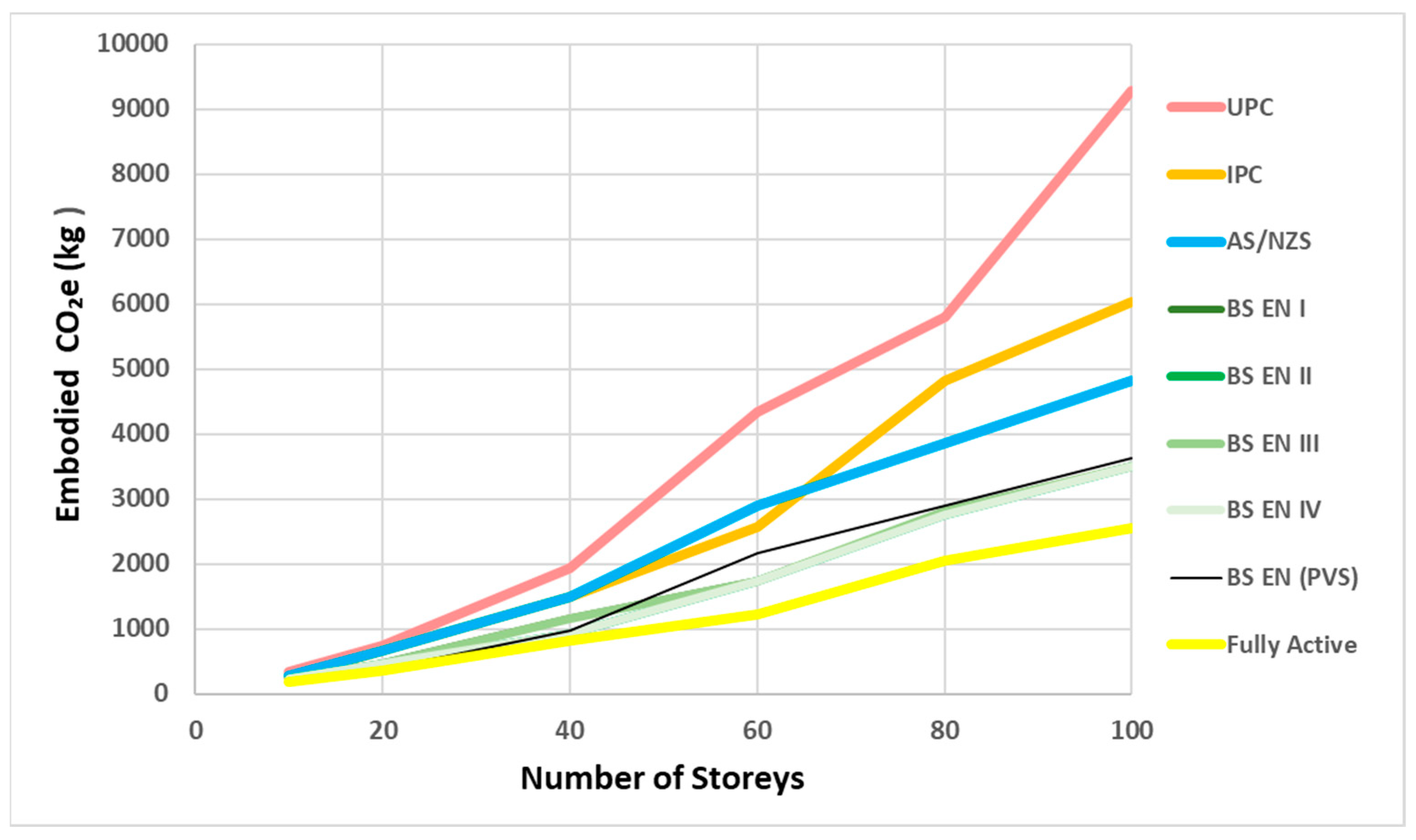
The embodied carbon emissions were calculated for each drainage design code across building heights, accounting for differences in system configuration and pipe sizing. Figure 5 provides a clear visual comparison of embodied carbon emissions from drainage pipework across buildings of varying heights, based on the four international design codes. It generally shows how each design recommendation affects overall embodied carbon emissions, revealing significant differences between them. This variation may be less notable in low-rise buildings, but it becomes increasingly evident in high-rise buildings.
To examine these disparities in greater detail and to show how the impact of each design recommendation scales with height, Figure 6 illustrates the embodied carbon emissions for each system and code across the 10 to 100 storey range. Overall, the European standard, represented by dark to light green lines (SVS) and a black line (PVS), consistently resulted in lower embodied carbon emissions compared to the other codes. This is because the code recommends relatively small vent pipe sizes. No significant differences were observed between its types (I, II, III, and IV) or configurations (PVS and SVS). This uniformity may reflect the underlying design principles of the code and the use of the same calculation method. In contrast, the American standards show the highest emissions, with the UPC (red line) and the IPC (orange line) occupying the upper range. This elevated level of embodied carbon emissions is likely attributable to overall system oversizing and the recommendation of larger vent pipes, particularly in high-rise buildings. The AS/NZS standard (blue line) generally falls above the European code but below the American codes. On the other hand, the fully active configuration (yellow line) consistently yields the lowest embodied carbon emissions, remaining at the bottom across all building heights. This is because parallel ventilation pipework is not required, which in turn significantly reduces material quantities.
While the European code and the fully active system demonstrated the lowest embodied carbon emissions in this study, it is important to consider technical performance alongside sustainability metrics. In general, providing sufficient PPRDs and AAVs in fully active systems helps to better control pressure transients in BDS. Thus, fully active systems not only enhance performance but can also reduce embodied carbon emissions by up to 73%, depending on the design code and building height.
To date, no directly comparable studies have examined embodied carbon emissions of BDS from the design code perspective. Related research has instead considered building service systems more broadly, comparing the embodied carbon of pipe materials to identify sustainable alternatives. While these studies consistently highlighted that building services represent a major share of embodied carbon in buildings, their aggregated scope offers limited insight into the specific contribution of drainage systems. In addition, current BDS design codes place greater focus on system performance and technical considerations such as hydraulic efficiency and pressure regulation, with little or no attention to the sustainability implications of their recommendations. By isolating BDS and evaluating different design approaches, this study demonstrates that system configuration and code requirements have a clear and measurable impact on embodied carbon outcomes. These results underscore the importance of considering both system configuration and design code selection when aiming to reduce the environmental impact of drainage systems. The considerable carbon savings associated with active configurations suggest that wider adoption of such systems could significantly contribute to advancing sustainable building design. This highlights the need for regulatory frameworks to integrate embodied carbon criteria and promote innovative drainage solutions in design standards.

5. Conclusions

This paper evaluated the sustainability of BDS in terms of associated embodied carbon across a range of building heights from 10 to 100 storeys, based on system designs derived from four major international design codes, BS EN 12056 (Europe), IPC and UPC (USA), and AS/NZS 3500 (Australia/New Zealand), for BDS in high-rise buildings. The analysis shows significant differences in terms of recommended pipe sizes between the different design codes. These differences were shown to result in considerable differences in pipe material usage and, ultimately, embodied carbon emissions associated with each system. The differences in the recommended system types, configurations, and pipe diameters across the different international design codes will also affect construction cost and space requirements, as well as resource usage and overall environmental performance.
The cradle-to-gate life cycle assessment demonstrated that the European code consistently resulted in lower embodied carbon emissions compared to the American codes (IPC and UPC) which are the highest, while the AS/NZS falls in between. Adopting fully active systems employing PPRDs and AAVs cuts embodied carbon emissions by up to 73%, depending on design code recommendations and building height. This finding calls for action by code developers and regulators to move beyond purely functional and performance-based criteria and to mandate or at least incentivise the inclusion of embodied carbon limits in future plumbing standards. Such measures will align design practices with broader sustainability goals and support the transition towards net zero.
While this study focused on PVC, the most widely used pipe material in BDS, its scope is limited by consideration of a single material and the adoption of a cradle-to-gate LCA boundary. Future research should therefore expand to include and compare alternative materials and employ cradle-to-grave data to capture installation, use, maintenance, and end-of-life stages. It should also explore the impacts of regional construction practices and assess the long-term performance of other system configurations of BDS.

Author Contributions

Conceptualization, S.M., M.G. and D.A.K.; methodology, S.M., M.G. and D.A.K.; software, S.M. and M.G.; writing—original draft preparation, S.M. and M.G.; writing—review and editing, S.M., M.G. and D.A.K.; review and editing; M.G. and D.A.K.; project administration; M.G. and D.A.K.; funding acquisition, M.G. and D.A.K. All authors have read and agreed to the published version of the manuscript.

Funding

This research was funded by Aliaxis S. A.

Institutional Review Board Statement

Not applicable.

Informed Consent Statement

Not applicable.

Data Availability Statement

The data may be obtained on request from the corresponding author.

Acknowledgments

The authors gratefully acknowledge the support provided by Aliaxis Group, especially Steven White and Yann Vincent, for their valuable guidance.

Conflicts of Interest

The authors declare no conflicts of interest.

References

  1. Huang, B.; Xing, K.; Rameezdeen, R. Exploring Embodied Carbon Comparison in Lightweight Building Structure Frames: A Case Study. Sustainability 2023, 15, 15167. [Google Scholar] [CrossRef]
  2. United Nations Environment Programme. Building Materials and the Climate: Constructing A New Future; United Nations Environment Programme: Nairobi, Kenya, 2023. [Google Scholar]
  3. Patil, M. What Do Circular Strategies Mean for Current HVAC Systems in Utility Buildings? Master’s Thesis, Delft University, Delft, The Netherlands, 2023. [Google Scholar]
  4. Rios, F.C. Beyond Recycling: Design for Diassembly, Reuse and Circular Economy in the Built Environment. Ph.D. Thesis, Drexel University, Philadelphia, PA, USA, 2018. [Google Scholar]
  5. Theißen, S.; Höper, J.; Drzymalla, J.; Wimmer, R.; Markova, S.; Meins-Becker, A.; Lambertz, M. Using Open BIM and IFC to Enable a Comprehensive Consideration of Building Services within a Whole-Building LCA. Sustainability 2020, 12, 5644. [Google Scholar] [CrossRef]
  6. Ostojic, S.; Traverso, M. Application of Life Cycle Sustainability Assessment in the Automotive Sector–A Systematic Literature Review. Sustain. Prod. Consum. 2024, 47, 105–127. [Google Scholar] [CrossRef]
  7. Itanola, M.; Griffiths, P.; Motawa, I. Closing the Loop in Building Services: A Systematic Review of Circular Economy Applications. Build. Serv. Eng. Res. Technol. 2024, 46, 293–315. [Google Scholar] [CrossRef]
  8. FAO Land and Water. Available online: http://www.fao.org/land-water/water/en/ (accessed on 26 April 2021).
  9. Huang, M.; Simonen, K.L.; Ditto, J. Life Cycle Assessment of Mechanical, Electrical and Plumbing in Commercial Office Buildings; The Carbon Leadership Forum: Seattle, WA, USA, 2019. [Google Scholar]
  10. Xiong, J.; Zhu, J.; He, Y.; Ren, S.; Huang, W.; Lu, F. The Application of Life Cycle Assessment for the Optimization of Pipe Materials of Building Water Supply and Drainage System. Sustain. Cities Soc. 2020, 60, 102267. [Google Scholar] [CrossRef]
  11. Simion, I.M.; Pennellini, S.; Awere, E.; Rosatti, A.; Bonoli, A. Enhancing Sustainability in Italian Water Supply Pipes through Life Cycle Analysis. Sustainability 2024, 16, 2685. [Google Scholar] [CrossRef]
  12. Nguyen, L.K.; Na, S.; Hsuan, Y.G.; Spatari, S. Uncertainty in the Life Cycle Greenhouse Gas Emissions and Costs of HDPE Pipe Alternatives. Resour. Conserv. Recycl. 2020, 154, 104602. [Google Scholar] [CrossRef]
  13. Chohan, I.M.; Ahmad, A.; Sallih, N.; Bheel, N.; Ali, M.; Deifalla, A.F. A Review on Life Cycle Assessment of Different Pipeline Materials. Results Eng. 2023, 19, 101325. [Google Scholar] [CrossRef]
  14. Istrate, I.R.; Juan, R.; Martin-Gamboa, M.; Domínguez, C.; García-Muñoz, R.A.; Dufour, J. Environmental Life Cycle Assessment of the Incorporation of Recycled High-Density Polyethylene to Polyethylene Pipe Grade Resins. J. Clean. Prod. 2021, 319, 128580. [Google Scholar] [CrossRef]
  15. Du, F.; Woods, G.J.; Kang, D.; Lansey, K.E.; Arnold, R.G. Life Cycle Analysis for Water and Wastewater Pipe Materials. J. Environ. Eng. 2013, 139, 703–711. [Google Scholar] [CrossRef]
  16. Kang, M.; Wei, J.; Yuan, J.; Guo, J.; Zhang, Y.; Hang, J.; Qu, Y.; Qian, H.; Zhuang, Y.; Chen, X.; et al. Probable Evidence of Fecal Aerosol Transmission of SARS-CoV-2 in a High-Rise Building. Ann. Intern. Med. 2020, 173, 974–980. [Google Scholar] [CrossRef]
  17. Cheng, C.L.; Lin, Y.Y. CFD Numerical Simulation in Building Drainage Stacks as an Infection Pathway of COVID-19. Int. J. Environ. Res. Public Health 2022, 19, 7475. [Google Scholar] [CrossRef]
  18. Xue, Y.; Stewart, C.; Kelly, D.; Campbell, D.; Gormley, M. Two-Phase Annular Flow in Vertical Pipes: A Critical Review of Current Research Techniques and Progress. Water 2022, 14, 3496. [Google Scholar] [CrossRef]
  19. Wong, L.T.; Mui, K.W.; Cheng, C.L.; Leung, P.H.M. Time-Variant Positive Air Pressure in Drainage Stacks as a Pathogen Transmission Pathway of COVID-19. Int. J. Environ. Res. Public Health 2021, 18, 6068. [Google Scholar] [CrossRef]
  20. Gormley, M. SARS-CoV-2: The Growing Case for Potential Transmission in a Building via Wastewater Plumbing Systems. Ann. Intern. Med. 2020, 173, 1020–1021. [Google Scholar] [CrossRef]
  21. Wang, Q.; Lin, Z.; Niu, J.; Choi, G.K.; Fung, J.C.H.; Lau, A.K.H.; Louie, P.; Leung, K.K.M.; Huang, J.; Cheng, P.; et al. Spread of SARS-CoV-2 Aerosols via Two Connected Drainage Stacks in a High-Rise Housing Outbreak of COVID-19. J. Hazard. Mater. 2022, 430, 128475. [Google Scholar] [CrossRef]
  22. Sharif, K.; Gormley, M. Integrating the Design of Tall Building, Wastewater Drainage Systems into the Public Sewer Network: A Review of the Current State of the Art. Water 2021, 13, 3242. [Google Scholar] [CrossRef]
  23. Gormley, M.; Campbell, D.P. The Transport of Discrete Solids in above Ground near Horizontal Drainage Pipes: A Wave Speed Dependent Model. Build. Environ. 2006, 41, 534–547. [Google Scholar] [CrossRef]
  24. BS EN 12056-2; Gravity Drainage Systems inside Buildings. Sanitary Pipework, Layout and Calculatioin. BSI Knowledge: London, UK, 2000.
  25. AS/NZS 3500.2; Plumbing and Drainage, Part 2: Sanitary Plumbing and Drainage. SA/SNZ: Sydney, Australia, 2003.
  26. UPC Uniform Plumbing Code TM; International Association of Plumbing Mechanical Officials: Ontario, CA, USA, 2003; ISBN 9094724111.
  27. International Code Council. International Plumbing Code IPC; ICC: Washington, DC, USA, 2003. [Google Scholar]
  28. Pomponi, F.; Moncaster, A. Scrutinising Embodied Carbon in Buildings: The next Performance Gap Made Manifest. Renew. Sustain. Energy Rev. 2018, 81, 2431–2442. [Google Scholar] [CrossRef]
  29. Lewandowski, K.; Katarzyna, S. A Brief Review of Poly(Vinyl Chloride) (PVC) Recycling. Polymers 2022, 14, 3035. [Google Scholar] [CrossRef] [PubMed]
  30. Martins, J.D.N.; Freire, E.; Hemadipour, H. Applications and Market of PVC for Piping Industry. Polimeros 2009, 19, 58–62. [Google Scholar] [CrossRef]
  31. Vahidi, E.; Jin, E.; Das, M.; Singh, M.; Zhao, F. Comparative Life Cycle Analysis of Materials in Wastewater Piping Systems. Procedia Eng. 2015, 118, 1177–1188. [Google Scholar] [CrossRef]
  32. Alsadi, A. Evaluation of Carbon Footprint During the Life-Cycle of Four Different Pipe Materials. Ph.D. Thesis, Louisiana Tech University, Ruston, LA, USA, 2019. [Google Scholar]
  33. BS EN15804; Sustainability of Construction Works—Environmental Product Declarations—Core Rules for the Product Category of Construction Products. BSI Knowledge: London, UK, 2021.
  34. BS EN 15978:2011; Sustainability of Construction Works—Assessment of Environmental Performance of Buildings—Calculation Method. BSI Knowledge: London, UK, 2012.
  35. Harnot, L.; George, C.B. TM65 Embodied Carbon in Building Services: A Calculation Methodology; CIBSE: London, UK, 2021. [Google Scholar]
  36. Hunter, R.B. Building Materials and Structures. Plumbing Manual; National Bureau of Standards: Washington, DC, USA, 1940. [Google Scholar]
  37. Kragh, J.; Rose, J.; Buhl, L.S. The Risks of Oversizing Domestic Water Piping–Measurement of Peak Flows in Multistory Residential Buildings. Build. Serv. Eng. Res. Technol. 2025, 46, 361–374. [Google Scholar] [CrossRef]
  38. Gormley, M.; Mohammed, S.; Kelly, D.A.; Campbell, D.P. Application and Validation of AIRNET in Simulating Building Drainage Systems for Tall Buildings. Buildings 2025, 15, 1725. [Google Scholar] [CrossRef]
  39. The Institute of Plumbing. Plumbing Engineering Services Design Guide; Chartered Institute of Plumbing and Heating Engineering (CIPHE): Hornchurch, UK, 2002; ISBN 1871956404. [Google Scholar]
  40. Swaffield, J.; Gormley, M.; Wright, G.; McDougall, I. Transient Free Surface Flows in Building Drainage Systems; Swales & Willis Ltd.: Exeter, UK, 2015; ISBN 9780203845769. [Google Scholar]
  41. BS EN 1329-1-2020; Plastics Piping Systems for Soil and Waste Discharge (Low and High Temperature) Within the Building Structure—Unplasticized Poly(Vinyl Chloride) (PVC-U). BSI Knowledge: London, UK, 2020.
  42. Circular Ecology Embodied Carbon—The ICE Database. Available online: https://circularecology.com/embodied-carbon-footprint-database.html (accessed on 19 August 2025).
  43. Hammond, G.; Jones, C. Embodied Carbon: The Inventory of Carbon and Energy (ICE); BSRIA: Bracknell, UK, 2011. [Google Scholar]
  44. Uni-Bell PVC Pipe Association l. Environmental Product Declaration; NSF International: Ann Arbor, MI, USA, 2023; Available online: https://www.uni-bell.org/Portals/0/ResourceFile/environmental-product-declaration-2023.pdf (accessed on 5 July 2025).
  45. Aliaxis Technical Services. Positive Air Pressure Attenuator (PAPA)–Best Practice Guide. 2017. Available online: https://www.emea-international.aliaxis.com/en/brands/studor/studor-products/productdetails/studor-p-a-p-a-861881 (accessed on 10 June 2025).
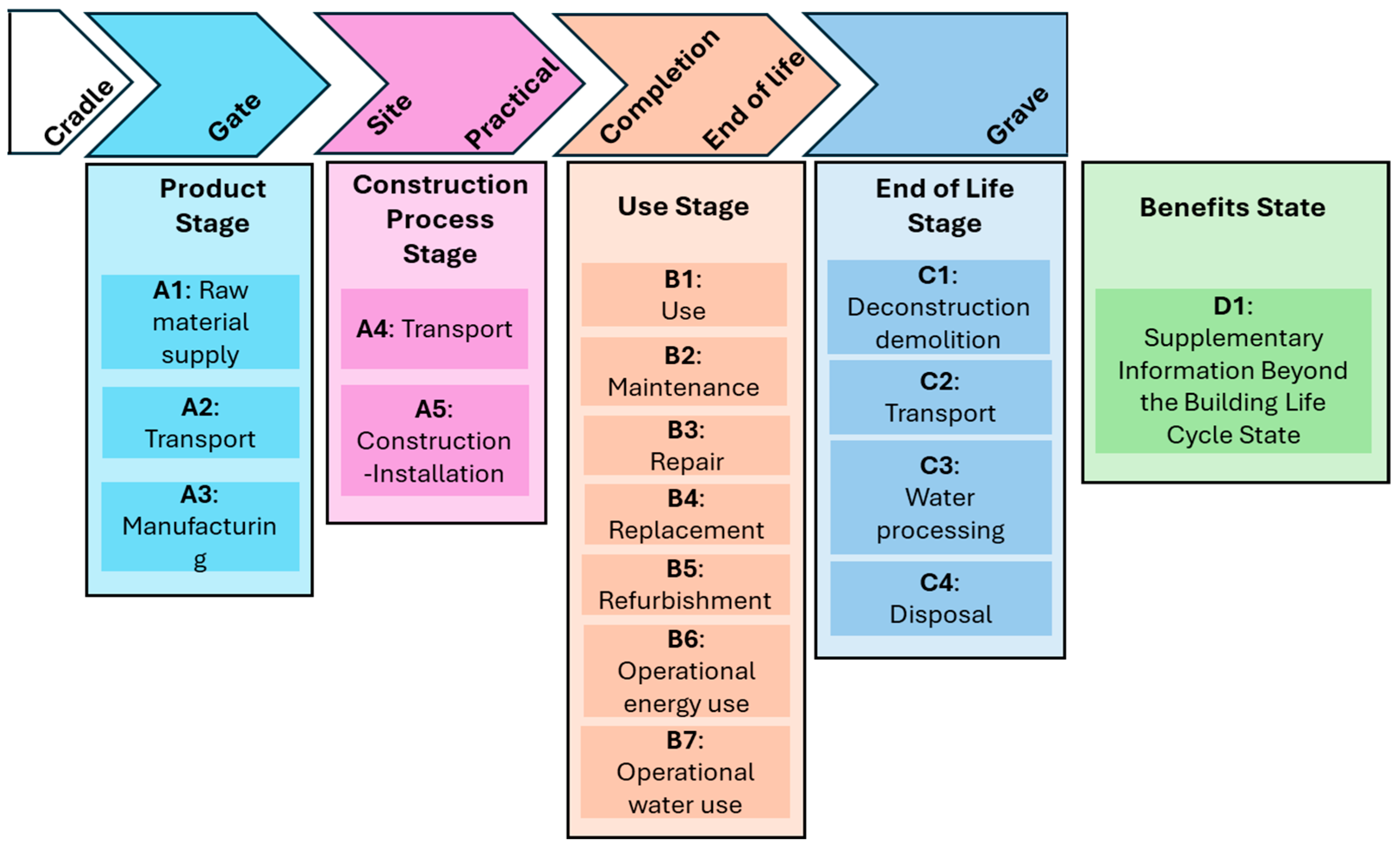
Figure 1. Full breakdown of life cycle stages (adapted from BS EN 15804, BS EN 15978 and CIBSE TM65).
Sustainability 17 08207 g001
Figure 2. Methodological flowchart for evaluating the embodied carbon of PVC pipework in BDS.
Sustainability 17 08207 g002
Figure 3. An example of the BDS configurations assessed in this study: (a) primary ventilated system, (b) secondary ventilated system and (c) fully active system.
Sustainability 17 08207 g003
Figure 4. Typical floor plan and layout of sanitary appliances in an apartment.
Sustainability 17 08207 g004
Figure 5. General visualisation of embodied carbon emissions (kg CO2 e) of drainage pipework for buildings ranging from 10 to 100 storeys, based on different design recommendations.
Sustainability 17 08207 g005
Figure 6. Detailed comparison of embodied carbon emissions (kg CO2 e) of drainage pipework for buildings from 10 to 100 storeys, illustrating differences across four international design codes and the fully active system.
Sustainability 17 08207 g006
Table 1. General properties of PVC pipe [30].
PropertyValueUnit
Density1380kg/m3
Young’s modulus2900–3300MPa
Tensile strength50–80MPa
Elongation@break20–40%-
Impact strength2–5kJ/m2
Glass temperature87°C
Melting point212°C
Vicat temperature85°C
Heat transfer coefficient0.16W/m.K
Linear expansion coefficient8.10–5/K
Specific heat0.9kJ/(kg·K)
Water absorption0.04–0.4-
Table 2. Individual and total DU/FU per apartment for the case study buildings.
Sanitary AppliancesDischarge UnitsFixture Units
BS EN 12056AS/NZSIPCUPC
IIIIIIIV
Hand wash basin0.50.30.30.3111
Bath0.80.61.30.5422
Shower0.60.40.40.4222
WC21.81.72433
Kitchen sink0.80.61.30.5322
Washing machine0.80.60.60.5523
Dishwasher machine0.80.60.20.5322
Total (per apartment)6.34.95.84.7221415
Table 3. Drainage pipe sizes based on different codes for various building heights.
No. of FloorsType of SystemStack/VentSize of Pipe DN in mm
BS EN 12056AS/NZSIPCUPC
IIIIIIIV
10PVSStack100100100100---
SVSStack100100100100100100100
Vent505050508075100
20PVSStack125100125100---
SVS Stack100100100100100100125
Vent50505050100100125
40PVSStack150125150125---
SVSStack125100125100125125150
Vent70507050125125150
60PVSStack150150150150---
SVSStack125125125125150125200
Vent70707070150 *150 *200
80PVSStack150150150150---
SVSStack150125150125150150200 *
Vent80708070150 *200 *200 *
100PVSStack200150150150---
SVSStack150150150150150150250 *
Vent80808080150 *200 *200 *
* the next larger or maximum available pipe size.
Table 4. Nominal diameters, wall thicknesses, and weight per metre for PVC pipes, with unit weights of PPRDs and AAVs.
PVC PipeWall ThicknessWeightWeight
Dia. (in)Dia. (mm)mmkg/mkg/unit
2503.250.341-
3753.250.517-
41003.50.821-
51253.50.935-
61504.31.471-
82005.252.245-
102506.653.554-
123008.35.257-
PPRD--3.2
AAV--0.4
Disclaimer/Publisher’s Note: The statements, opinions and data contained in all publications are solely those of the individual author(s) and contributor(s) and not of MDPI and/or the editor(s). MDPI and/or the editor(s) disclaim responsibility for any injury to people or property resulting from any ideas, methods, instructions or products referred to in the content.