Abstract
The escalating demands of industrial applications, particularly those involving severe wear, temperature, and corrosive environments, present significant challenges for the long-term strength of critical components, often fabricated from high-value materials such as super duplex stainless steel alloys. Super duplex can withstand the corrosive environment (in particular, crevice corrosion and pitting damage) and maintain mechanical integrity sufficient for high-pressure pumping applications such as seawater injection and crude oil. Conventional repair methodologies frequently result in component rejection due to process-induced distortions or detrimental phase transformations, contributing to substantial material waste and hindering the adoption of circular economy principles. This research addresses this issue by developing and validating a novel repair process utilizing laser metal deposition (LMD) additive manufacturing. The research focuses on establishing optimized process parameters to ensure the salvaging and restoration of damaged super duplex components while preserving their requisite mechanical integrity and corrosion resistance, in accordance with industry standards. Comprehensive characterization, including microstructural analysis, chemical composition verification, hardness profiling, and mechanical fatigue testing, confirms the efficacy of the LMD repair process. This work demonstrates the potential for extending the service life of critical components, thereby promoting resource efficiency and contributing to a more sustainable and resilient industrial paradigm.
1. Introduction
Additive manufacturing (AM) is a pivotal technology in driving the transition towards a sustainable and circular economy, particularly through its application in repair and remanufacturing. Beyond simply extending product lifespans by restoring damaged components, AM fundamentally alters material flow by minimizing waste through precise, layer-by-layer deposition, a stark contrast to traditional subtractive methods. This resource efficiency is further amplified by the ability of AM to utilize recycled materials as feedstock, closing material loops and lessening the demand for virgin resources. The on-demand production of spare parts, enabled by AM, reduces the environmental burden of excess inventory and long-distance transportation, fostering localized, more agile supply chains. Moreover, the design flexibility of AM facilitates the creation of components optimized for durability and ease of repair, embedding circularity principles into the product’s very design. By enabling the production of lightweight components and contributing to reduced energy consumption during manufacturing and product use, AM actively works to lower the carbon footprint of industrial processes. To fully realize these benefits, ongoing advancements in sustainable material compatibility and life cycle assessment are crucial, ensuring that AM continues to be a driving force in creating a more environmentally responsible and resource-efficient manufacturing paradigm.
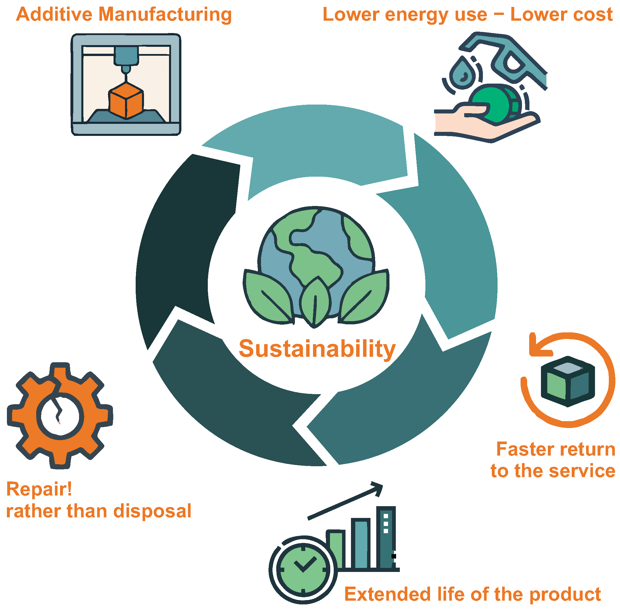
Figure 1 provides a visual representation of the multifaceted role AM plays in promoting sustainability within a circular economy framework. At its centre lies the concept of sustainability, encircled by five core benefits that AM offers. These include AM itself, emphasizing the technology’s precision and efficiency; “Lower energy use–Lower cost,” showcasing its potential for reducing both environmental impact and production expenses; and “Faster return to service,” highlighting its ability to streamline repair and remanufacturing processes. Additionally, “Repair rather than disposal” reflects AM’s contribution to waste minimization by enabling component restoration, while “Extended life of the product” underscores its role in prolonging product utility. Collectively, these elements illustrate how AM not only supports greener manufacturing practices but also fundamentally reshapes the lifecycle of products—from design and production to maintenance and reuse—thereby embedding sustainability at every stage. Collectively, the illustration in Figure 1 serves as a concise yet powerful summary of AM’s strategic alignment with sustainable development goals and resource-efficient manufacturing paradigms.

Figure 1.
Benefits of additive manufacturing for circular economy that support sustainability.
The current market conditions are financially challenging and, as such, manufacturing industries are looking for methods of prolonging product life using cost effective repair methods as opposed to replacement of expensive parts and long lead time repairs. For oil-and-gas extraction, marine exploration, and other ocean technologies where the operating environment is corrosive and abrasive [1], the use of duplex and super duplex stainless steels is common [2]. These alloys (which are available in both cast and wrought forms) have a good combination of high strength, ductility, and corrosion resistance, which makes their application beneficial for processes such as pumps for sour process fluids and seawater services. The alloys are normally specified with a minimum pitting resistance equivalent number (PREN = %Cr + 3.3%Mo + 16%N) [3]. This formula provides a useful guide to the corrosion performance of different stainless steel grades. Standard duplex stainless steels have a PREN of circa 35 and super duplex stainless steels have a PREN > 40. To achieve consistent PREN values, the chemical composition and thermal processing (heat treatment) need to be accurately monitored and controlled within well-defined limits. The alloys are typically supplied in the solution annealed condition and the target microstructure is 50:50 austentite–ferrite [4] and free from undesirable intermetallic phases. The same manufacturing practices and acceptance criteria need to be observed when conducting fusion welding repair processes.
Furthermore, the properties of duplex and super duplex stainless steel are tailored to withstand corrosive environments, in particular crevice corrosion and pitting damage, and maintain mechanical integrity sufficient for high-pressure pumping applications such as seawater injection and crude oil, and also low-pressure pumps such as seawater lift and fire pump duties. However, duplex and super duplex components such as pump shafts that incur minor damage in service or during manufacturing have to be rejected and replaced with expensive and long lead time counterparts.
As the world is drilling deeper for reserves, super duplex components are required for more arduous operating environments and can experience damage due to fretting, erosion, and other types of wear. Conventional welding methods to repair super duplex can have a detrimental affect on the components that experience high temperatures for a long period of time—intermetallic phases can start occurring in the base material at very low temperatures (starting at 300 °C through to 1000 °C). The control of the welding process is essential for super duplex materials, including the avoidance of heat treatment during pre- and post-weld, and interpass temperature should be below 150 °C to avoid precipitations of intermetallic phases, as detailed by the API RP 582 [5] standard. A list of the intermetallic phases and the temperatures associated with them according to [6] are shown in Table 1. These phases generally take time to develop and are not instantaneous. Lopez et al. (1999) [7] showed a 27.2% drop in the ductility of duplex that was exposed to 10 h of heat treatment at 675 °C, causing the σ-phase to develop.

Table 1.
Precipitation of intermetallic phases of super duplex [6].
Recent advances [8,9,10] have been made to investigate the effects of additive manufacturing on duplex/super duplex materials. However, effort is required in the early design process to effectively remanufacture components in relation to the material selection process [11]. The deployment of additive manufacture technology for the design, manufacture, and remanufacture of high-value super duplex components is relatively new to industries; additive manufacture promises to lower costs and reduce lead times while at the same time offering better functional, environmental, and remanufacturing performance [12].
This paper details the development and validation, at technology readiness level (TRL) 6, of a new remanufacturing process based on additive manufacturing for the repair and salvaging of pump shafts, and in particular repairing one of the most challenging locations on the pump shaft, i.e., the coupling location. The design function of the shaft coupling location is to transmit torque loads between shafts, as in the case of (large vertically orientated) seawater lift and fire pumps, which commonly have a dozen or more shafts coupled together. Therefore, the coupling is a critical design feature, and repair of this area needs to be undertaken using fully evaluated and controlled processes.
The additive manufacturing method, laser metal deposition (LMD), was used to repair the coupling location. The process parameters were defined to maintain mechanical and corrosion-resistant properties in accordance with industry standards. A semi-quantitative chemical composition of the additive layers, heat affected zone (HAZ), and substrate was obtained using energy dispersive X-ray spectroscopy, and the status of intermetallic phases was determined by etching procedures. Hardness and fatigue behaviours were also investigated. Based on the research in this paper, the expected resulting industrial impacts of the new remanufacturing process are significant, with a lead time reduction from 6–10 weeks to 1–2 weeks and repair cost only 25% of the replacement cost.
2. Previous Works
Full-scale fatigue testing was performed in [13] on wrought AISI-SAE 4140H samples laser clad with martensitic stainless steel overlays with different preheat levels. It has been confirmed experimentally [13] that both cladding process and preheating induce the compressive residual stress state, resulting in an improved fatigue life of the processed samples. However, the introduction of larger defects during the cladding process eliminates such improvements, resulting in minimal fatigue strength, similar to that shown by the base material, or even worse.
Fatigue testing was conducted in [14] to investigate the potential of applying LMD as a repair method for Ti-6Al-4V aerospace components. Ti-6Al-4V powder was laser deposited on Ti-6Al-4V specimens [14] with two different deposition strategies: a raster pattern with a continuous deposit (LMD-1) and a raster pattern deposit with an inter-track pause (LMD-2). The results showed that the fatigue lives of LMD-1 were higher when compared to LMD-2. This is because tensile residual stress in the deposit layer for LMD-1 was 150 MPa, which was 50% lower compared to that in LMD-2 (250 MPa). The high number of geometrical defects, in LMD-2 in addition to higher tensile residual stress, was the factor contributing to the shorter fatigue life when compared to LMD-1. Thus, heat treatment with lower temperature and longer duration is better for fatigue resistance.
Ref. [15] focuses on developing basic fatigue resistance data for 17-4 PH stainless steel deposits made using the LMD process. The study [15] demonstrated that heat treatment has an opposite effects on mechanical properties and fatigue resistance. The specimens that were direct aged (A) with interlayer temperature control and longer interlayer dwell times were observed to have a larger volume fraction of austenite (retained austenite and reverted austenite) in the microstructure compared with SA (solution treatment + ageing) and HSA (homogenization & solution treatment + ageing) samples. The differences in the microstructure resulted in varying the mechanical behaviour of the material, as evidenced by results from tensile and fatigue tests. Direct aged samples (A) have a much lower yield strength but much better fatigue resistance compared to SA and HSA samples, which are twice as strong in terms of yield. Thus, aggressive heat treatment types have no benefit for fatigue resistance.
By selecting the appropriate process parameters and welding strategy, it is possible to achieve tensile and fatigue strengths [16] which are at least equal to the original material. Ref. [16] investigates laser beam cladding, which is an established industrial precision process in the field of aero engine and gas turbine repair. The high-cycle fatigue testing was done on base and clad samples, with the duration of tests up to 10 million cycles. All specimens fractured outside the laser-generated zones in the base material. Thus, the fatigue strength of the laser-deposited structures apparently exceeds that of the base material. It was also found that the fatigue strength of the Ti6242 material used for the cladding experiments is slightly higher than that of the previously tested Ti6242 reference material. Thus, the fatigue resistance of repaired material can be no worse than of the base one, at least in the case of titanium alloys.
Laser cladding of AerMet100 powder on AerMet100 substrate was performed in [17] to demonstrate the viability of repair. The selected material [17], AerMet100, is a widely used ultra-high-strength steel in current and next generation aerospace components, such as landing gears. No micro-cracking and very little porosity were observed in the clad layer. A variable amplitude fatigue load was used for 1000 MPa maximum load and 0.1/0.7 load ratios. Both the as-clad and post-heat-treated (PHT) samples were compared to a baseline sample, with an artificial notch to simulate damaged condition. Results show that laser cladding significantly improves fatigue life, as compared to the baseline sample with a notch. However, the fatigue life of the as-clad sample is lower as compared to a baseline sample without a notch. A compressive residual stress of 300–500 MPa was observed in the clad region. The PHT condition, however, was not effective in improving the fatigue life—it was in fact the opposite, rather negative.
Based on observations in [13,14,15,16,17], it can be concluded that this research work completely agrees with previous similar studies, especially in [17] regarding the negative effect of PHT condition and the better fatigue resistance of baseline undamaged material. The samples with 50% LMD have a drop in fatigue resistance compared to the base material, because of the defects (porosity, etc.) induced by LMD. Forged/cast materials are most often better in fatigue resistance compared to their AM variants. As the samples are preheated before LMD, they thermally expand, and after LMD they shrink, thus generating additional compressive residual stresses in the deposited layer. The induced residual stress in the surface layer partly compensates for the negative influence of the defects from AM on the fatigue resistance. Therefore, the additionally applied thermal treatment actually has a negative effect on the structure and the material, because it eliminates the positive effect of compressive residual stress, and should be avoided. The suggestion would be to replace a heat treatment with a mechanical treatment, e.g., shot peening. This would increase the material density by closing the subsurface pores and increase the depth of the compressive residual stress penetration and peak value.
3. Experimental Procedure
3.1. LMD Process
The LMD facility of Laser Additive Solutions Ltd. (based in Doncaster DN11 0PS, UK) was used for the repair of the coupling location on the pump shaft. The following LMD equipment was used:
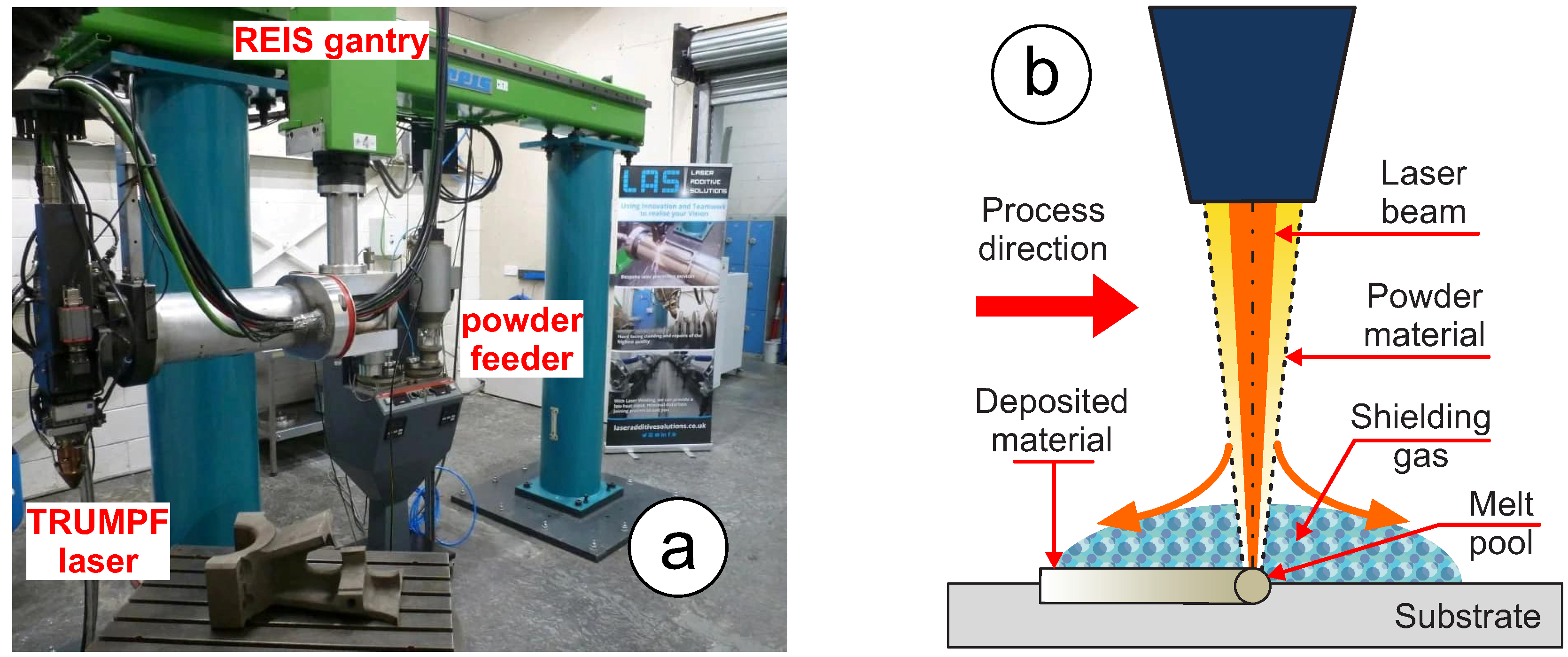
- TRUMPF 2 kW TruDisk laser (made by TRUMPF Ltd. based in Luton LU2 9NL, UK) that has adaptive laser spot size, as shown in Figure 2a.
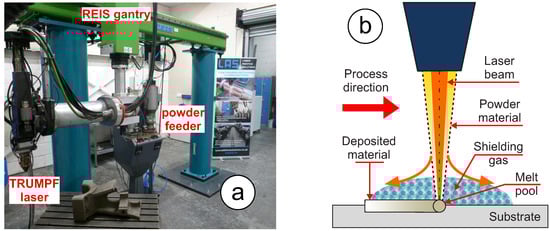 Figure 2. LMD experimental process: (a) LMD equipment at Laser Additive Solutions (LAS) Ltd., (b) schematic of the LMD process.
 - 5-axis REIS RL80 gantry manipulation system (made by Reis Robotics GmbH based in Obernburg 63785, Germany), as shown in Figure 2a.
- Oerlikon Metco twin-10-C powder feeder (made by Oerlikon Metco AG headquartered in Pfäffikon, Schwyz, Switzerland), as shown in Figure 2a.
- Mebitec TopLas3D v3 – CAD/CAM software capable of full 3D programming.
A schematic of the LMD process is shown in Figure 2b, which annotates key aspects of the process, such as the laser beam, powder feed, and shielding gas.
3.2. LMD Repair of Coupling Location on Pump Shaft
One of the most challenging locations on the pump shaft to repair is the coupling location. The design function of the shaft coupling location is to transmit torque loads through the keyways of shafts, and it is therefore a critical design feature and repair of this area needs to be undertaken using fully evaluated and controlled processes. The keyway in the coupling location does not need to be repaired. However, the damage that is noted in the coupling location is approximately 100 mm in length and 0.5 mm maximum depth, as shown in Figure 3. For the investigation in this paper, a common size of pump shaft of around 50 mm diameter and 2 m long was used. And prior to LMD repair the coupling location was machined back by 0.5 mm (radial) and 100 mm length to represent a “typical damaged” area, as shown in Figure 4a. The shafts were then vertically suspended in a furnace at 200 °C, the furnace temperature was raised at a maximum heating rate of 100 °C/h to 330 ± 10 °C, and the shafts were held at this temperature for 2.5 h before being cooled in still air to relieve the stresses, as carried out in some major industries.
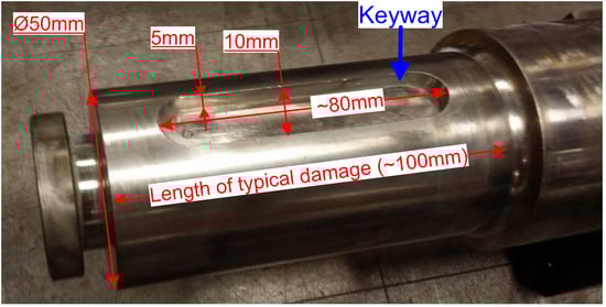
Figure 3.
Damaged coupling location with the keyway.
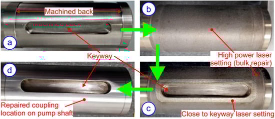
Figure 4.
LMD repair of coupling location: (a) keyway at the coupling location and “damage” machined back on bar; (b) LMD deposit onto coupling location (view from opposite side of keyway); (c) LMD deposit onto coupling location (view from top of keyway); (d) LMD deposit machined back at coupling location (view from top of keyway).
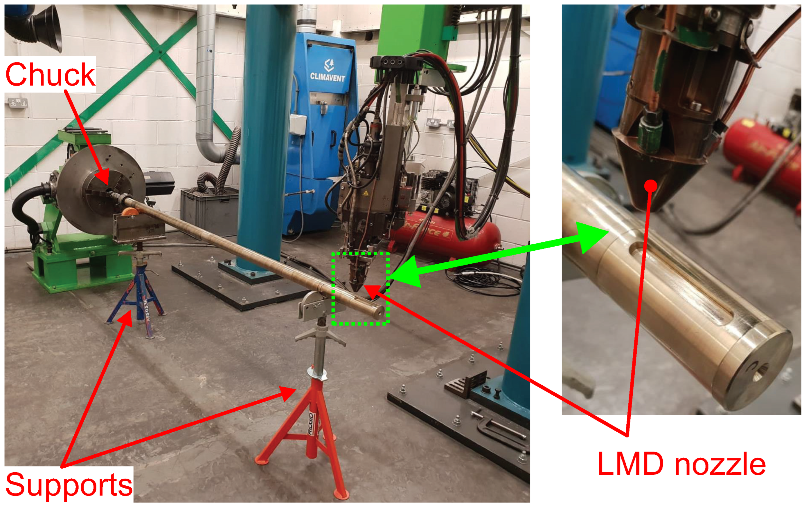
The setup for the repair of the coupling location is shown in Figure 5—the shaft is supported at one end by the chuck, and two support rollers were used to reduce the run out of the shaft. Super duplex in powder form was deposited by the LMD machine on to the coupling location, as shown in Figure 4b. For the bulk of the coupling location, as shown in Figure 4c, three layers were deposited using optimised high-power laser settings for fast deposition, and close to the keyway, three layers were deposited using the reduced power and spot size close to keyway laser settings to better control the deposit. On the keyway, a “lip” was created (Method B) instead of Method A in order to meet the dimensions of the keyway—a schematic of this is shown in Figure 6. The “lip” is very small and can be removed with a file and grinding paper, creating a straight edge on the keyway. Method A would have created the potential for undesirable weld undercut features to occur to the keyway.

Figure 5.
LMD machine setup for repair on coupling location.
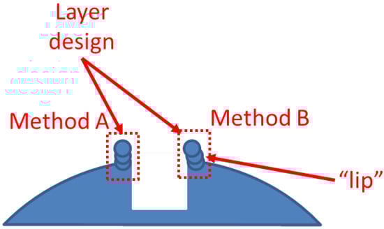
Figure 6.
LMD layer design at the keyway.
The laser and gas settings are shown in Table 2 and Table 3, respectively. The settings for the process were carefully chosen to minimise the component temperature, thereby reducing the formation of intermetallic phases, which are known to be detrimental in super duplex stainless steels, as shown in Table 1. By optimising parameters such as laser power, processing speed, and layer deposition strategy, we ensured that the thermal input remained controlled, reducing prolonged exposure to critical temperature ranges where undesirable phases, such as sigma or chi phases, could form. This approach helped get closer to a desired microstructural balance of austenite and ferrite, preserving the mechanical integrity and corrosion resistance of the repaired components. In all settings, argon was used as the carrier and nozzle gas, and a 30% weld bead overlap was used between weld runs. Furthermore, the deposition created a rough surface due to the semi-diffused powder particles on top of the final layer, and therefore machining was carried out to remove the rough surface, as shown in Figure 4d.
Table 2.
High and close to keyway laser settings.
Table 3.
Carrier and nozzle gas settings.
3.3. Characterization
3.3.1. Temperature and Straightness Measurements
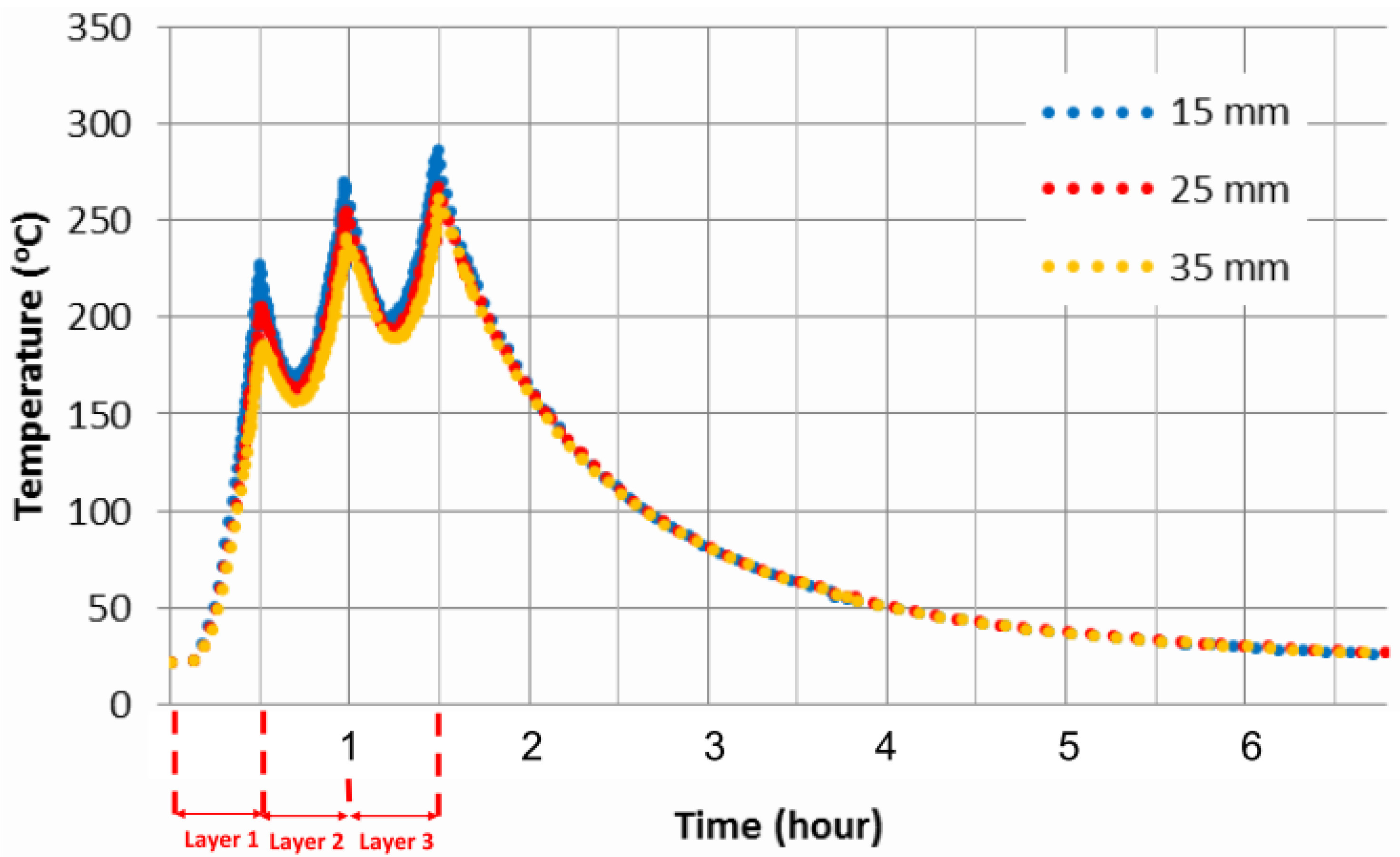
Thermocouples were used to determine the temperatures during the worst-case scenario of cladding at one end of the shaft. The worst-case scenario is formed by cladding the shaft without any dwell times. In comparison, dwell times reduce the overall temperature and are currently standard in repairing the coupling location due to the complexity of the cladding around the keyway as many measurements are required during the process to align the laser head and shaft at the required working distance. Furthermore, thermocouples were placed 15, 25, and 35 mm away from the edge of the overlay along the shaft, as shown in Figure 7, and temperatures were recorded throughout the LMD stage. In addition, the straightness of the shafts were measured pre- and post-LMD work using a dial gauge along several locations on the shafts and at 90° intervals around the circumference. During the measurements, the shaft was suspended on two v-blocks.
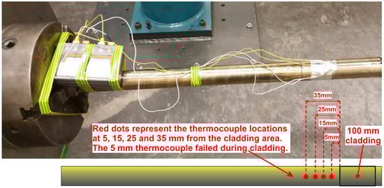
Figure 7.
Thermocouple locations on bar.
3.3.2. Mechanical Testing
Two mechanical testing procedures were used to assess the ductility of the repaired area. The first test consisted of a mechanical bend procedure widely used in industry, in accordance with ASME BPVC.IX [18] code. The specimens for this test were cut out, using a mechanical saw and water jet cutting equipment, in approximately 10 mm thick rectangular sections of the repaired area that consisted of both LMD overlay and substrate. The sections were subjected to ASME BPVC.IX [18] specified loads with an acceptance criterion of no crack formation on neither the overlay nor the substrate. Furthermore, to understand in more depth the mechanical properties of the LMD-repaired area, fatigue testing was undertaken using an ESH 120 kN capacity servo hydraulic test machine, along with Instron hydraulic grips under cyclic (compression–tension) loading. This fatigue testing method has a symmetric stress cycle (R = −1) and therefore resembles a piece of rotating equipment that has a symmetric loading profile (minimum to maximum absolute values). The specimens used in this investigation consisted of 50:50 LMD and original wrought super duplex alloy, as shown in Figure 8.
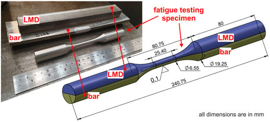
Figure 8.
Fatigue test specimen—50% bar of pump shaft and 50% LMD.
Furthermore, eight specimens were used in total during the fatigue testing. Initially, four of the specimens were machined out from a super duplex shaft, which set the benchmark fatigue limit. The remaining four specimens were machined out from a super duplex shaft with LMD, as shown in Figure 8. In addition, the super duplex bar of shaft portion of this was cut out into a semi-cylindrical shape using a wire electrical discharge machining (EDM) process and then milled to remove the wire EDM-affected area by 0.5 mm. The curved section on the super duplex shaft was also milled to create a flat surface to prevent any movement during the LMD stage. Laser cladding was deposited onto the milled back wire EDM surface, with high-power laser settings of 950 W. Since it was not possible to remove fatigue testing coupons from the additive manufactured coupling location, the setup adopted under the fatigue testing in this paper was the most practical solution to machining out a coupon with 50% shaft and 50% LMD overlay. This approach is novel since it is more robust and easier to implement as it allows the interface to be exactly at the mid line between the shaft and the LMD overlay.
3.3.3. Dye Penetrant Inspection
Dye penetrant inspection (DPI) was carried out in accordance with ASME BPVC.IX [18] on the LMD overlay after machining back of the top rough surface. The DPI method was used to check for surface defects, including hairline cracks and porosity. DPI was done using Magnaflux products, which specializes in non-destructive testing (NDT)—a brand owned by Illinois Tool Works (ITW) headquartered in Glenview, Illinois, USA. The following DPI steps were carried out:
- Cleaning of surface: the test surface was cleaned at the start of the DPI to remove dirt, oil, and grease using Magnaflux Spotcheck SKC-S Cleaner/Remover.
- Application of penetrant: Magnaflux Spotcheck SKL-SP2 Red Penetrant was applied to the surface, with a dwell time of 30 min.
- Removal of excess penetrant: the excess penetrant was removed with Magnaflux Spotcheck SKC-S Cleaner/Remover.
- Application of developer: the white Magnaflux Spotcheck SKD-S2 Developer was applied to draw out penetrant from defects to visually indicate them on the surface.
3.3.4. Hardness Testing
Hardness tests are carried out to evaluate the strength and ductility of a material. Hardness is evaluated by indenting the surface with a specific load and then measuring the depth of the penetration or the size of the impression left by the indenter. Initially, microhardness testing was carried out on the LMD overlay and substrate using a Mitutoyo MVK-G1 digital micro-hardness tester with a 200 g load. Furthermore, macro-hardness measurements were taken at a ground surface on the LMD overlay for a comparative study. These measurements were taken from indents with a 5 kg load.
3.3.5. Corrosion Testing
G48 “Method A” corrosion test, in accordance with ASTM v.03.02 [19], was undertaken with an acceptance criteria of weight loss of <4.0 gm−2 on the LMD-repaired samples and no pitting when examined at ×20 magnification. This is an accelerated corrosion test that is widely used in industry. The samples were subject to a ferric chloride solution heated to 35 °C for 24 h. Also, prior to this the samples went through an A380 passivation process using a nitric acid solution in accordance with ASTM v.01.03 [20]. The passivation process is used to rebuild the passive layer, which is usually damaged from external factors such as machining.
Furthermore, to evaluate the corrosion rates, potentiodynamic polarisation tests were conducted in a jet impingement testing apparatus (image and schematic diagram shown in Figure 9). An electrically conductive cable was connected to the reverse side of the test samples, as shown in Figure 9, which were subsequently cold mounted, exposing a test surface area of approximately 2 cm2. The tests were conducted under static (quiescent) conditions at 40 °C in 3.5%NaCl (approximately seawater salinity) aqueous solution.
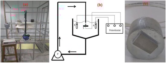
Figure 9.
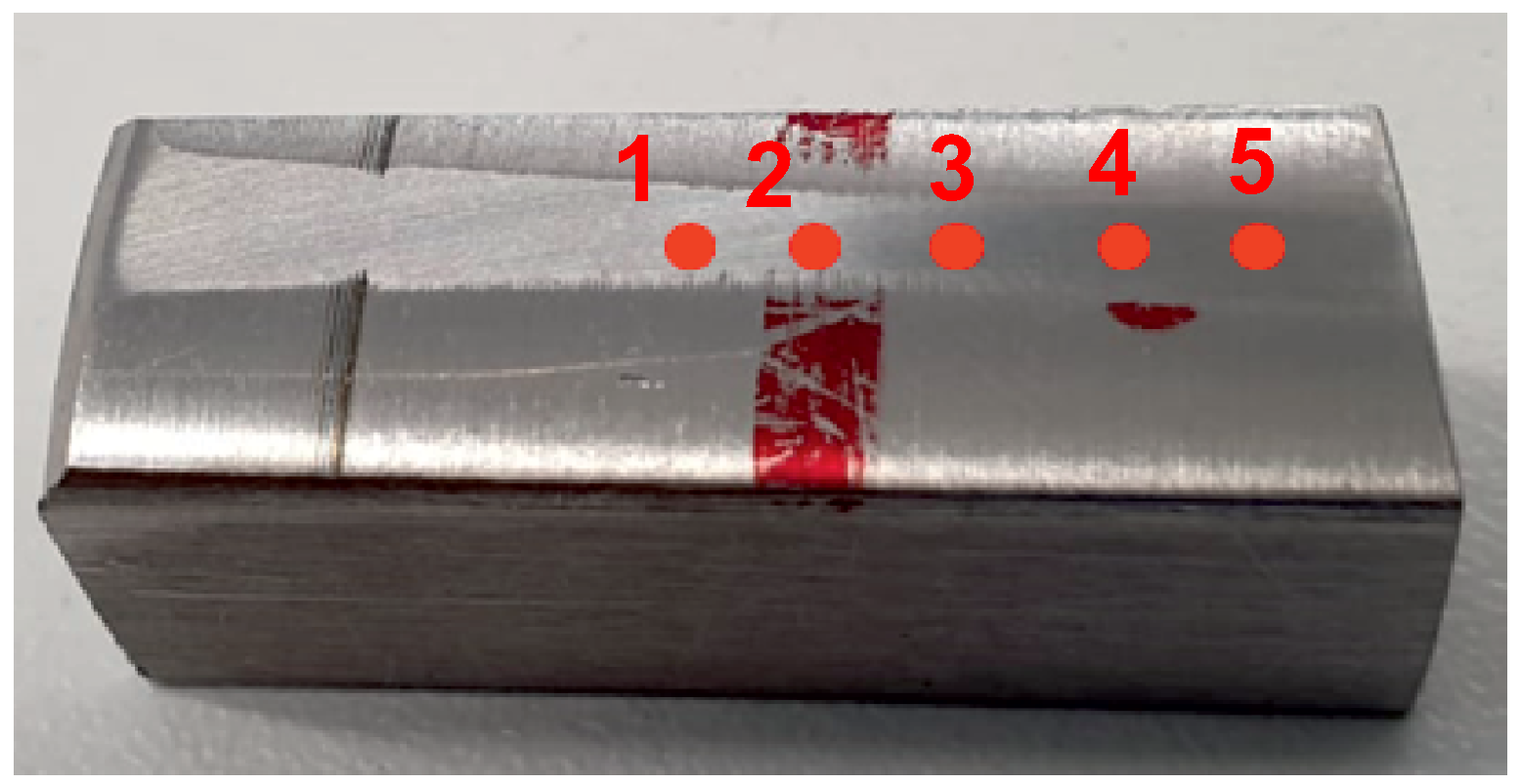
Jet impingement apparatus used in the potentiodynamic polarisation tests: (a) laboratory setup; (b) schematic diagram; (c) potentiodynamic polarisation test sample.
3.3.6. Microstructural Investigation
Samples for the microstructural investigation were cut to approximately 20 × 20 mm from the LMD overlay and substrate, mounted, polished to 0.05 μm diamond paste, and electrolytically etched with 10% oxalic acid electrolytic. The samples were observed under a light optical microscope (LOM) for observations of the microstructural characteristics, and in particular of the heat affected zone and dilution. LOM was also used to check for micro-cracks and porosity. Furthermore, scanning electron microscopy (SEM) was used to observe the microstructure at higher magnification of the powder, LMD overlay, and substrate. And energy dispersive X-ray spectroscopy (EDS) was used for the semi-quantitative chemical analysis. For both SEM and EDS, a Hitachi S-3700 tungsten filament scanning electron microscope with an accelerating voltage was used, which was manufactured by Hitachi High Tech Corporation based in Minato-ku, Tokyo 105-0003, Japan.
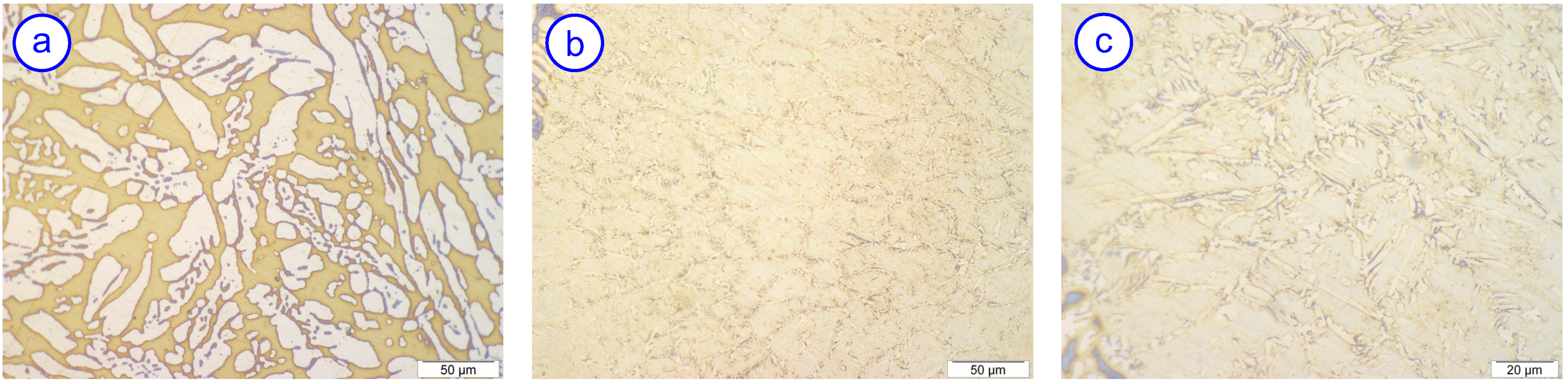
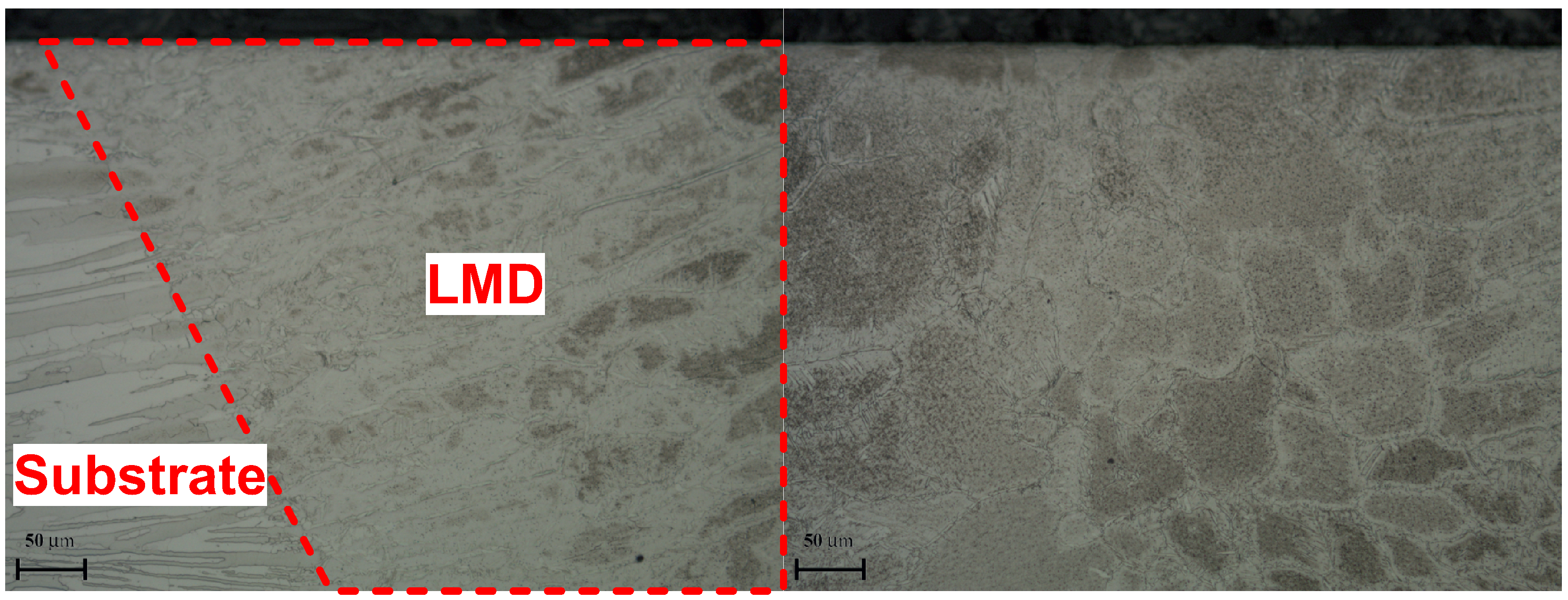
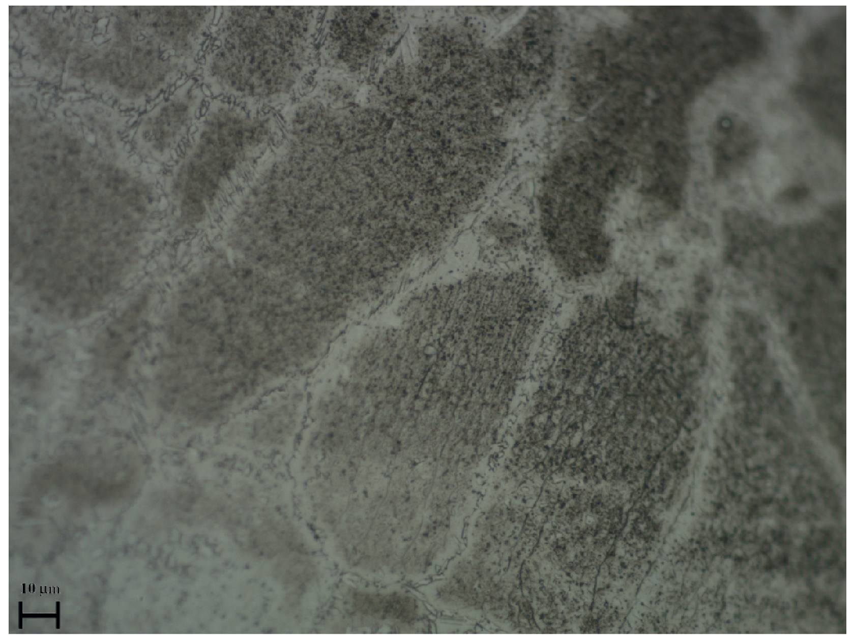
Two phase measurement methods were used to pick up the phases present in the LMD overlay and substrate. The samples were first etched in a solution of potassium ferricyanide and potassium hydroxide—Murakami’s reagent according to ASTM E407 [21] etchant number 98. If present, this method stains carbides and sigma phases. The samples were then electrolytically etched in 40% KOH at 2.5 V according to ASTM E407 [21] etchant number 97. This method is used to stain sigma, chi, and ferrite phases. Furthermore, the ferrite content of the substrate was determined over 16 adjacent fields, using a grid of 25 points. The ferrite content was conducted as per ASTM E562 [22] at ×500 magnification, as shown in Figure 10a for base metal and Figure 10b for cladding, and at ×1000 magnification, as shown in Figure 10c for cladding. And a ferrite scope was also used to determine the ferrite content by magnetic induction.
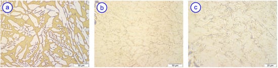
Figure 10.
Typical duplex microstructure: (a) base metal—magnification ×500; (b) cladding—magnification ×500; (c) cladding—magnification ×1000.
4. Results and Discussion
4.1. Temperature Control and Straightness Measurements
Excessive heat penetration of super duplex material at long time periods can cause catastrophic effects, including reduction in mechanical and corrosive resistance properties of the alloy due to the precipitation of intermetallic phases. Due to the difficulty of welding super duplex materials, the temperatures were very closely monitored during the LMD process in order to develop the best parameters to repair the super duplex without greatly affecting its mechanical and corrosion resistance properties, i.e., low heat/energy input to the material was a prerequisite.
The total time for cladding all tracks in each layer during the worst-case scenario was just below 30 min, and three layers were clad. The recorded temperatures are plotted over time in Figure 11. As can be seen from this figure, there is a cumulative effect with increasing bulk temperatures with each additional weld pass, and this resulted in the maximum interpass temperature of 150 °C being exceeded. After the final layer was clad, the peak recorded temperature took 38 min to cool down from 287 °C to below the interpass temperature. Whilst this was undesirable, it is thought that the short temperature excursions during the overlay will not have any damaging effect to either the weld deposit or the base material. At the lower embrittling temperatures (circa 300 °C), the holding time would need to be many hours before any effect would occur.
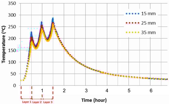
Figure 11.
Temperature during the laser cladding of the coupling location on the bar.
Furthermore, the difference of the dial gauge measurements pre- and post-LMD after machining were minimal, and the maximum distortion occurred close to the coupling location since a large amount of heat transfer took place in this location, but the distortion was very low (around 0.01 mm).
4.2. Bend Testing and DPI
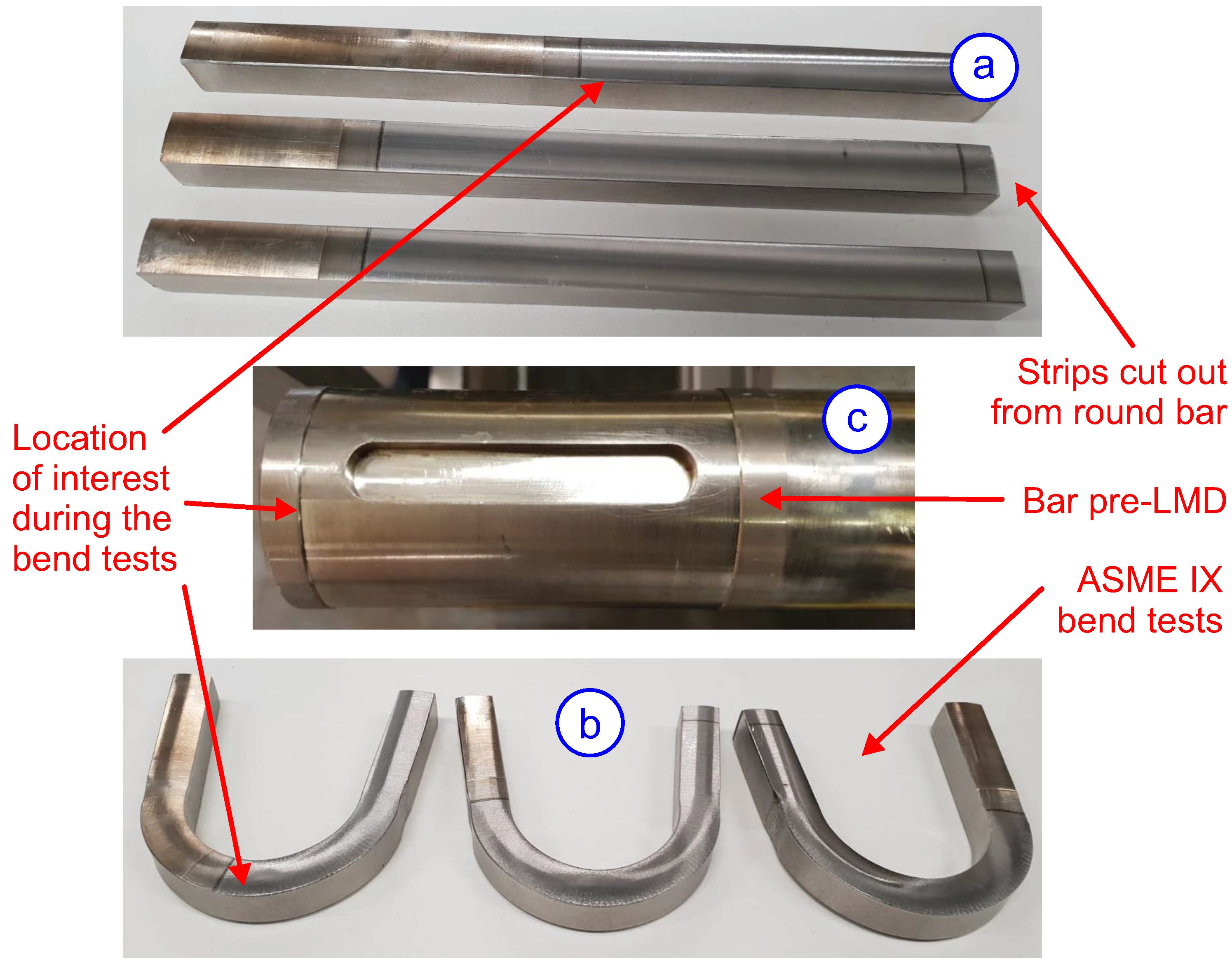
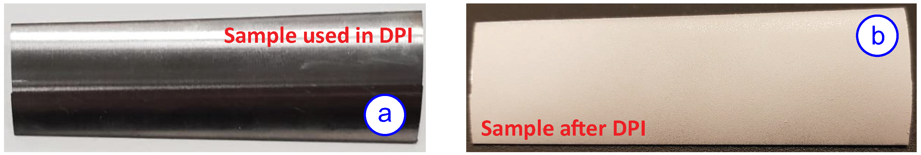
ASME BPVC.IX [18] mechanical bend tests were undertaken primarily to assess the ductility of the base alloy and LMD overlay. All tests were successful; that is, both the base alloy and LMD exhibited excellent ductility and no cracks were observed. In addition, under the DPI method when the developer was applied to the LMD overlay, no surface defects were noticed. If defects were present, they would be visible as they would be stained. The bend-tested samples in accordance with ASME BPVC.IX [18] are shown in Figure 12, with the testing results and acceptance criteria tabulated in Table 4. Dye penetrant inspection (DPI) was carried out in accordance with ASME BPVC.IX [18] on the LMD overlay (after machining), as shown in Figure 13a. No surface defects were noticed after the developer was applied, as shown in Figure 13b. If defects were present, they would be visible as they would be stained.

Figure 12.
Mechanical bend testing according to ASME BPVC.IX [18]: (a) specimens with cladding cut out of the bar and subjected to ASME IX loads; (b) successfully passed specimens; (c) bar pre-LMD.
Table 4.
Industry standard testing results and acceptance criteria.
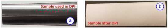
Figure 13.
Dye penetrant inspection (DPI) according to ASME BPVC.IX [18]: (a) machined back sample from LMD overlay of coupling location; (b) sample with developer as part of DPI.
4.3. Fatigue Testing
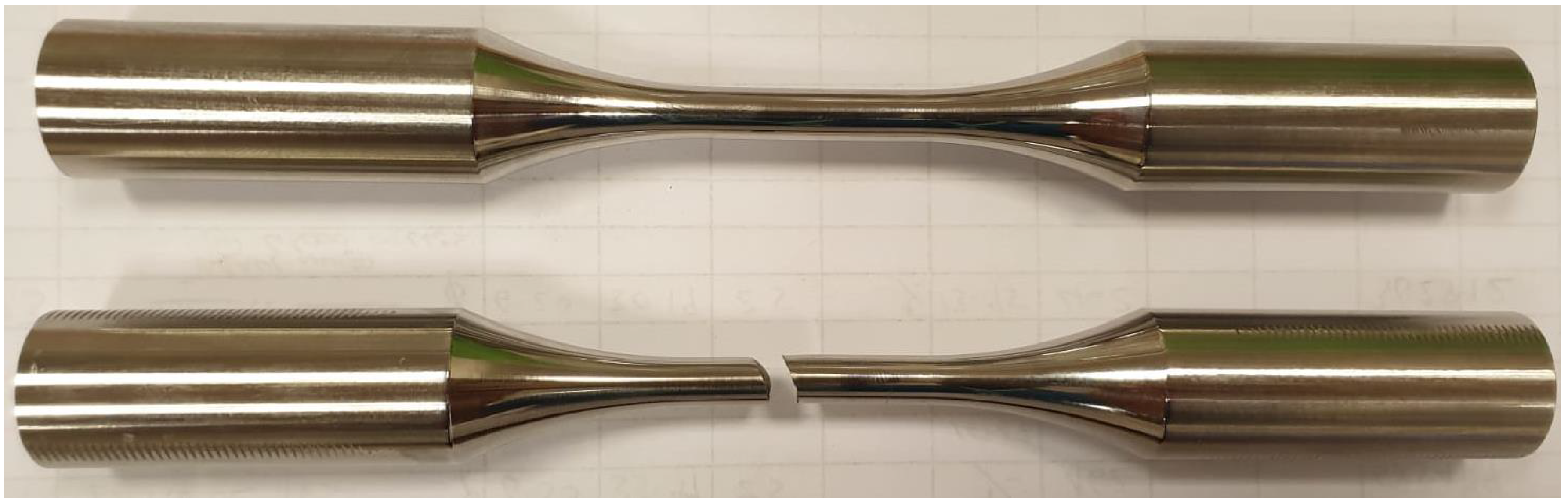
Furthermore, to understand in more depth the mechanical properties of the LMD-repaired area, fatigue testing was carried out. All specimens were tested for high cycle fatigue under a cyclic load with a symmetric compression–tension cycle (R = −1) until fracture, as shown in Figure 14 The stress amplitudes for cyclic testing was chosen to induce the mechanism of high cycle fatigue (HCF) using the stress-life approach for results interpretation. The applied force was chosen to keep the peak stress just below the yield strength to stay in the HCF domain and to avoid cyclic plastic strain corresponding to low cycle fatigue (LCF). The fatigue testing results are shown in Table 5, with eight tests performed in total. Two runs were carried out for each stress amplitude level and for each material (base and 50% LMD). An average variation in fatigue life for the base material is only 10%, while it increases to 23.5% for 50% LMD specimens, which can be explained by inhomogeneous microstructure, presence of residual stresses, pores, inclusions, etc.
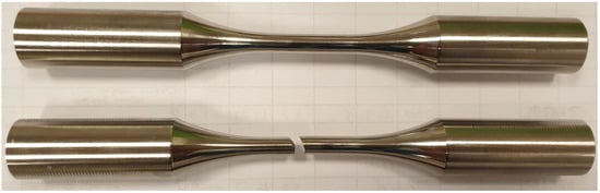
Figure 14.
Sample tested for high cycle fatigue under symmetric compression–tension load with stress amplitude of +/− 462 MPa at 8 Hz until fracture.
Table 5.
Fatigue test results.
The results show that the fatigue life of the sample with 50% LMD has just over half the fatigue life of the sample cut from the base metal without LMD. The reduced fatigue life of the LMD samples may be due to the ferrite content in the overlay, when higher amounts of ferrite lower the material toughness according to [25]. However, the fatigue life of the sample with 50% LMD is 70% of the benchmark sample that has been stress relieved. In addition, stress-relieved samples exhibit earlier fractures, i.e., at lower load cycles in comparison to non-stress-relieved samples. An increase in hardness was noticed [26] when stress relieving super duplex at 350 °C for a few hours and therefore reducing ductility and potentially fatigue resistance.
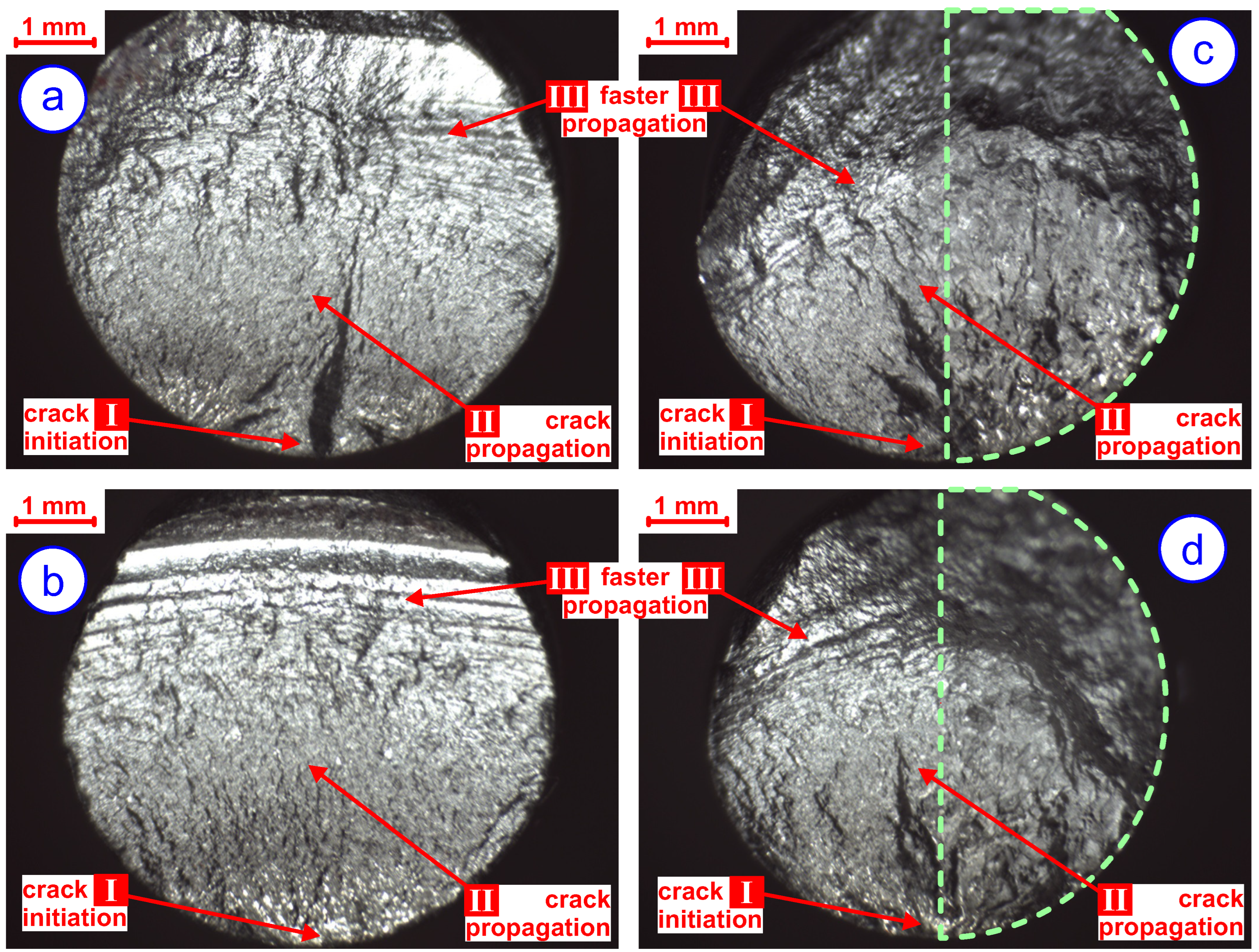
Furthermore, fractographic images of the respective test piece fracture surfaces were recorded using an optical stereo-microscope, as shown in Figure 15. The fractographic features of the benchmark trials with and without stress relieving are shown in Figure 15a,b, respectively. And the fractographic features of the samples with 50% LMD with and without stress-relieving trials is shown in Figure 15c,d, respectively. All of the fatigue test specimens exhibited classic fatigue marking (refer to [27,28] for a comprehensive investigation) for the initial stages of cracking, and this is followed by an area of fast/final rupture. The crack origin positions all coincided with the surface of the specimens.
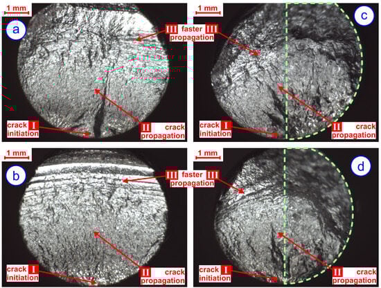
Figure 15.
Microstructure of the fracture surfaces: (a) benchmark trial with stress relieving; (b) benchmark trial without stress relieving; (c) sample with 50% LMD (dashed green) and with stress relieving; (d) sample with 50% LMD (dashed green) and without stress relieving.
Fatigue life reduction in 50% LMD test specimens may arise primarily from AM process-induced imperfections: residual tensile stresses promote crack initiation, microstructural inhomogeneities and porosity create stress concentration points, rough surface finishes accelerate crack formation, heat-affected zone alterations weaken the material. And most likely in this case a lack of fusion or metallurgical defects may provide a crack initiation site. These factors, stemming from LMD’s rapid thermal cycles, compromise resistance to cyclic loading, especially at the initial stage. This assumption is supported by the observation of the fatigue crack origin on the 50% LMD test pieces, which coincides with the outer surface of the specimens and at the intersection of the LMD/base material location, as can be seen in Figure 15c,d.
4.4. Hardness Investigation
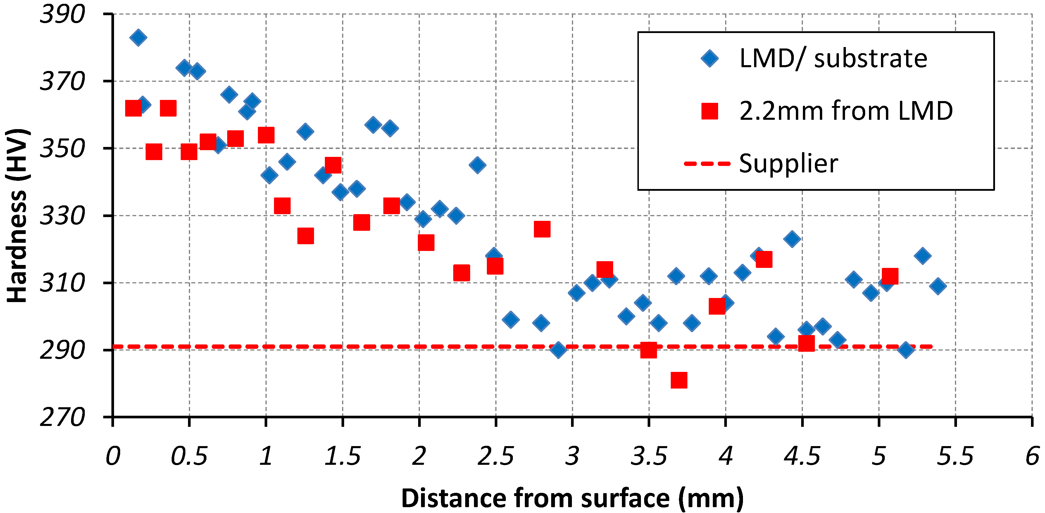
The hardness tests were conducted using a Mitutoyo MVK-G1 digital micro-hardness tester using a 200 g load. The hardness plot for the LMD overlay and substrate is shown in Figure 16. The hardness is up to 92 HV higher than the supplier’s nominal data in the overlay. The closer the overlay is to the substrate, the closer the hardness is to the supplier’s nominal levels. It is thought that some of the higher hardness is caused by the machining back of the surface, which has led to work hardening effects—this is a common difficulty when machining or drilling stainless steels, in particular austenitic based ones [29]. The micro-hardness measured 2.2 mm away from the LMD, also plotted in Figure 16, is up to 71 HV higher than the supplier’s nominal data in the overlay. Furthermore, macro-hardness measurements were taken at the surface of the overlay, as shown in Figure 17, with corresponding values reported in Table 6. Five individual indents were used for the macro-hardness measurements, and these values have an average of 345 HV. This is around 55 HV higher than the supplier’s nominal data in the overlay. For both micro- and macro-hardness measurements, the increase in hardness is considered to be within acceptable limits. Similarly, an increased hardness in the weld area was noticed in [30], when using laser welding without filer material.
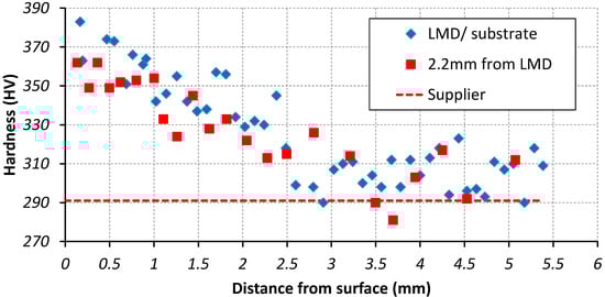
Figure 16.
Micro-Hardness testing using 200 g load for the super duplex laser cladding in the coupling location of the bar.
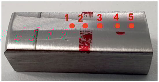
Figure 17.
Macro-hardness specimen with measurement points taken at red dots as listed in Table 6.
Table 6.
Macro-hardness measurements taken in points according to Figure 17.
4.5. G48 Method A Corrosion Test and Potentiodynamic Polarisation Scans
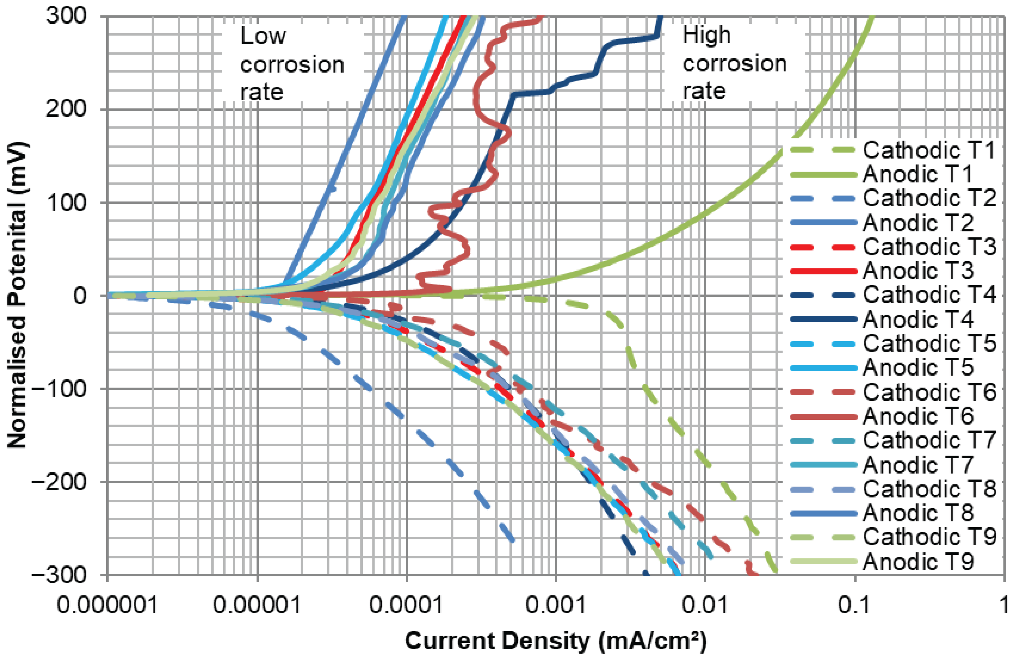
All LMD overlay and substrate samples passed the ASTM G48 Method A corrosion test in accordance with the standard ASTM v.03.02 [19], as shown in Table 4, with no weight loss and no pitting at ×20 magnification. In addition, potentiodynamic polarisation scans were conducted to assess the corrosion behaviour of the test materials (high- and low-power laser setting overlays of super duplex compared to wrought [rolled bar] super duplex), as shown in Figure 18. The potentiodynamic polarisation scans involved conducting scans in both anodic (more electropositive from the free corrosion potential, ) and cathodic (more electronegative from ) directions. The tests were conducted by shifting the potential either 300 mV above (anodic) or below (cathodic) . In order to calculate the corrosion rates of the materials, the Tafel extrapolation method was used to evaluate the corrosion current density, . From this, Faraday’s Law was used to calculate the corrosion rate in terms of mm/yr. For clarity, the higher the corrosion current density, , the larger the corrosion rate (i.e., polarisation scans which are furthest on the right on the x-axis, as shown in Figure 18, have the highest corrosion rates).
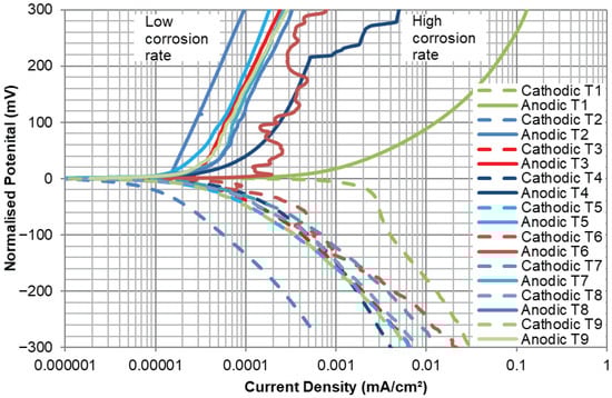
Figure 18.
Comparison of cathodic and anodic reactions of the super duplex overlay LMD investigations with wrought (rolled bar) super duplex.
In order to assess the test materials’ resistance to localised corrosion (pitting and crevice resistance), potential breakdown tests were conducted. This was done by shifting the electrode potential electropositive until the passive film broke down and the initiation of pits commenced. The breakdown potentials of all LMD tests were greater than 1 V (Ag/AgCl reference electrode), which is indicative of materials with good resistance to localised corrosion.
The corrosion rates, breakdown potentials, and reduction in corrosion rates compared to wrought (rolled bar) super duplex and of all LMD tests are shown in Table 7. The wrought super duplex and all LMD tests exhibited extremely small corrosion rates (<0.02 mm/year) in static condition in 3.5%NaCl aqueous solution. This would be expected for corrosion-resistant materials. Materials with poor corrosion resistance would typically exhibit a corrosion rate greater than 0.1 mm/year in the same testing environment. To summarise, all LMD test samples exhibited a significant reduction in corrosion rate (>91%) compared to wrought super duplex and exhibited similar resistance to localised corrosion. This backs up the findings from the G48 corrosion test.
Table 7.
Corrosion rates of all LMD and wrought super duplex investigations.
4.6. Microstructural Investigation
4.6.1. Light Optical Microscopy
Microstructural images of the super duplex laser cladding using the high-power laser setting are shown in Figure 19. Further microstructural images of the super duplex laser cladding using the close to the keyway laser setting is shown in Figure 20. It was noticed from these images that good quality overlays had been produced that were free from defects such as porosity. Also, in these figures, a similar structure is noted to that of laser treatment on super duplex [31] and of the laser beam trials carried out on duplex [32,33] using bead-on-plate conditions. The overlay solidification structure is comprised mainly of ferrite with grain boundary networks of austenite. Fine, well dispersed particles suspected to be silicate or other oxide/slag inclusions were observed throughout the overlay. However, these fine dispersed particles do not appear to have adversely affected weld quality (as demonstrated by the successful industry standard bend-test coupons and corrosion testing). The high proportion of ferrite in the overlay appears to be in excess of the phase balance limit typically found in duplex stainless alloys. It is considered that the higher proportion of ferrite in the weld may be due to the extremely fast rate of cooling experienced during and after solidification. A similar behaviour was noticed in [34,35]. Commercially available duplex stainless alloys typically have the most desirable balance of properties (tensile strength, ductility, toughness, corrosion resistance) when microstructure phase proportions of ferrite/austenite are around the range of 50/50–60/40.
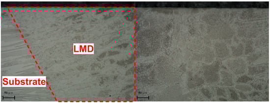
Figure 19.
Microstructure (etched) of high-power laser setting near final track and bulk overlay shown on the (left) and (right) image, respectively.
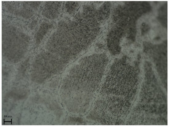
Figure 20.
Microstructure (etched) of “close to keyway” laser setting.
4.6.2. SEM and EDS
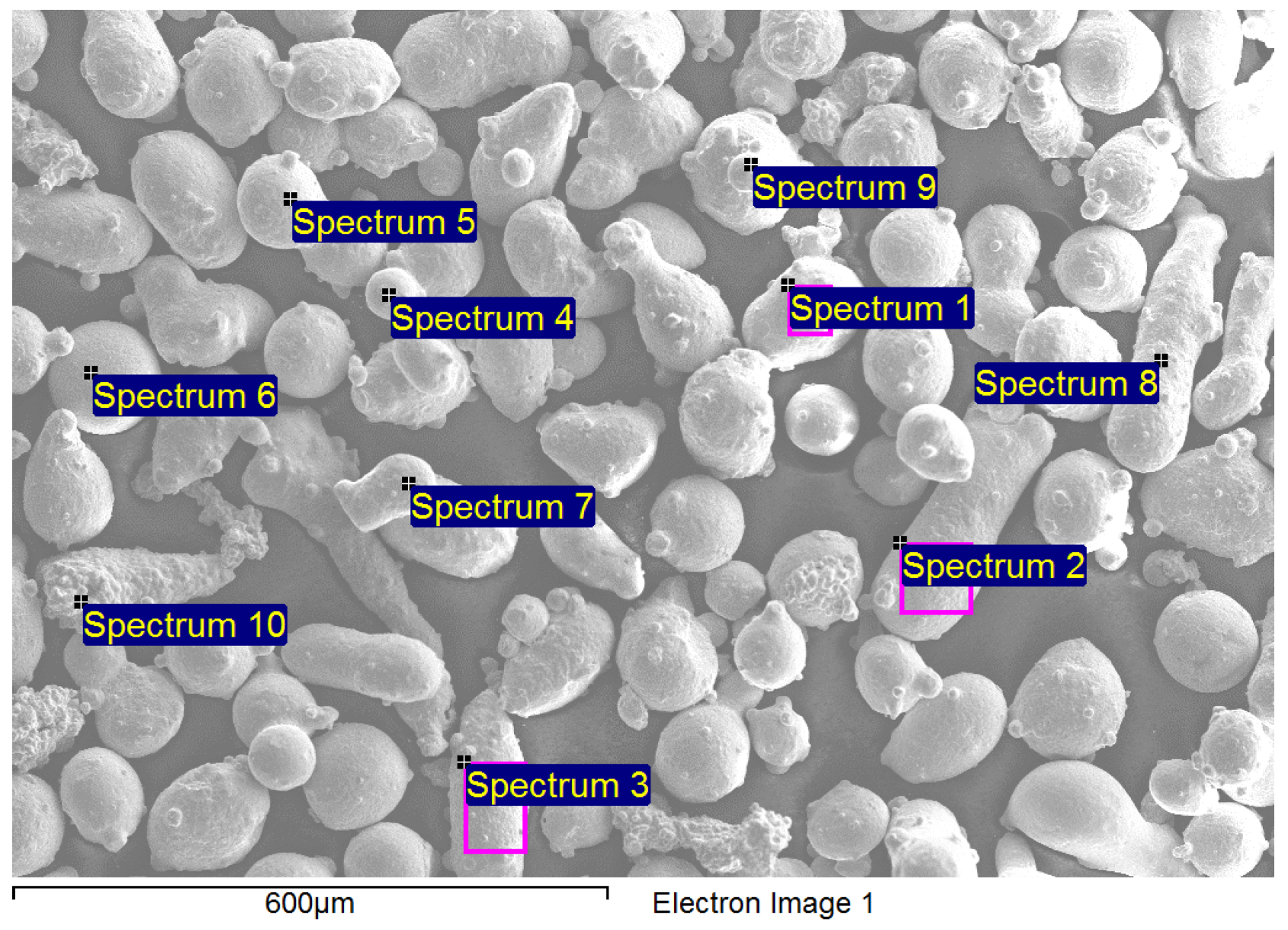
The powder particles that were used during the cladding on the coupling location of the shaft are shown in Figure 21. It was noticed that the chemical composition using point and area spectrums in SEM was in close agreement with the supplier’s nominal composition, as shown in Table 8. In addition, the powder was predominantly spherical with a size around 100 microns, and some elongated irregular shaped particles were also noted. As there was no such powder readily available in the market, this had to be created as a one-off; it is thought that higher quality powder that has almost all particles the same optimised size will further enhance the cladding qualities.

Figure 21.
SEM of super duplex powder used in the laser cladding.
Table 8.
SEM and supplier’s data of chemical composition of super duplex powder used in the laser cladding. All results in weight %.
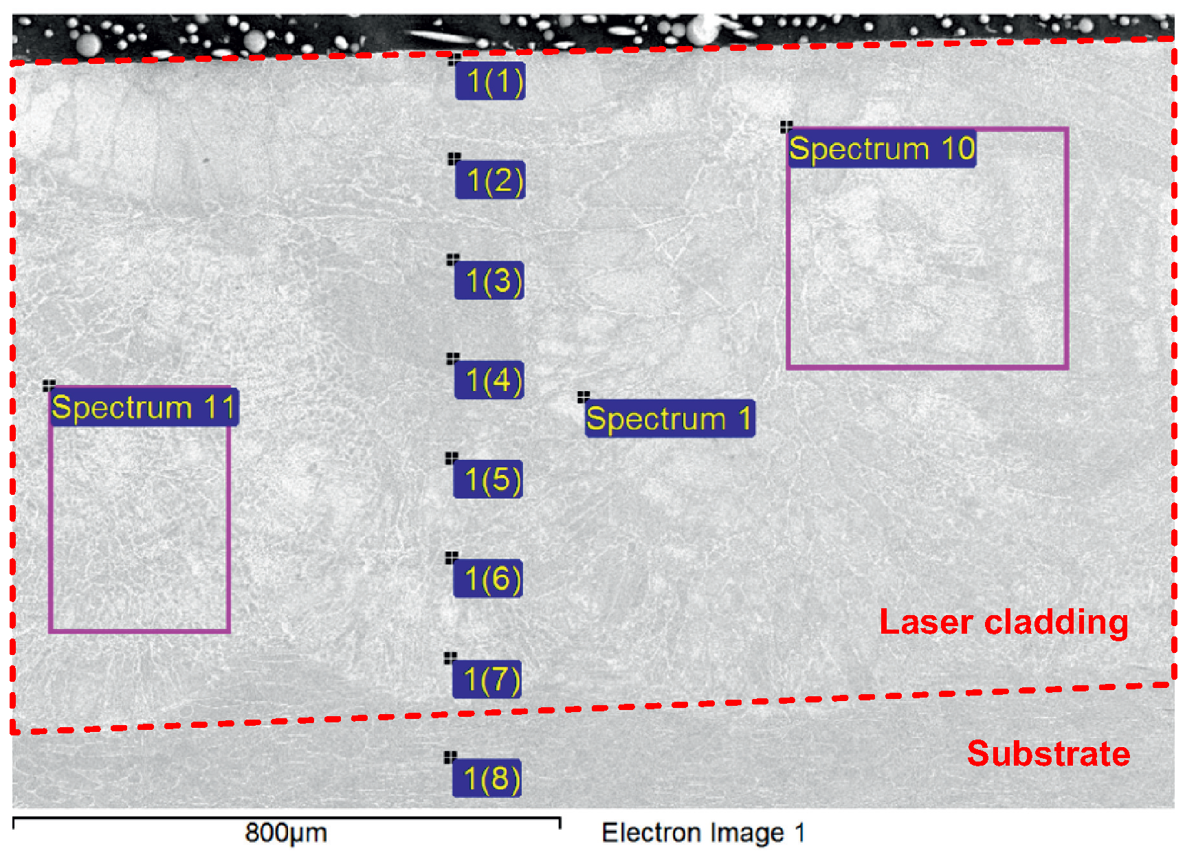
Furthermore, the chemical composition of the super duplex laser cladding on the super duplex substrate are shown in Figure 22 (tabulated in Table 9). It was noticed that the chemical composition was in close agreement with the supplier’s nominal composition. The cooling and reheating between each layer had no significant detrimental effects on the microstructure chemical composition, and a full dilution into the substrate was observed with no micro-cracks and porosity. Although the dilution was small, it did not affect the bonding strength, as proven by the successful ASME mechanical bend tests. In order to increase the dilution, one way is to increase the laser power, as detailed in [36]. However, in this case the dilution was deliberately kept small with lower laser power settings to avoid high temperature zones for long periods that create detrimental phases.
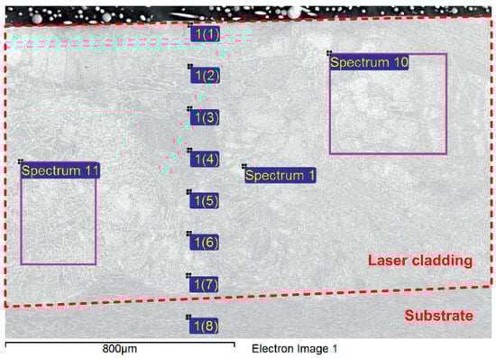
Figure 22.
SEM of super duplex laser cladding (red dashed lines) using “close to keyway” laser settings on super duplex substrate.
Table 9.
SEM and supplier’s data of chemical composition of super duplex laser cladding and substrate. All results in weight %.
4.6.3. Phase Investigation
The microstructure after etching according to ASTM E407 [21] etchant number 98 (if present, stains carbides, and sigma phase) had no intermetallic phases present in the LMD overlay and substrate. Samples were then etched according to ASTM E407 [21] etchant number 97 (if present, stains sigma, chi, and ferrite phases) with the intention of preferentially colouring ferrite and leaving austenite unaffected. This etchant worked as expected in the parent material but could not be fully resolved in the overlay. The results of both tests are tabulated in Table 4.
Furthermore, the ferrite content of the substrate was measured according to ASTM E562 [22], and it was within the typical range of duplex stainless steel material, 35 to 55% [24], as shown in Table 4. Since this method could not be used to determine the ferrite content in the overlay due to the fine microstructural features present, a ferrite scope was used instead. The ferrite content measured by the ferrite scope is shown in Table 3 of both the substrate and cladding at different locations and is within the typical range of duplex stainless steel material.
5. Conclusions
The paper discusses the development and validation of a laser metal deposition AM process for repairing damaged super duplex stainless steel components, addressing challenges in traditional repair methods and promoting sustainability in industrial applications. A new remanufacturing process, validated at TRL 6, is based on AM for the repair and salvaging of pump shafts for oil-and-gas applications. The repair of coupling location is addressed in this work as one of the most challenging locations on the pump shaft from a structural integrity point of view. This research directly contributes to the principles of a circular economy by extending the lifespan of critical components, reducing the need for raw material extraction and minimizing waste. By enabling the repair and reuse of damaged pump shafts, this process offers a sustainable alternative to traditional repair and replacement methods, leading to a reduced environmental footprint and promoting resource efficiency. The quality of the repair work and corresponding area was validated using the following types of testing:
- Passed ASME IX mechanical bend test;
- Passed ASTM G48 Method A corrosion test;
- Passed dye penetrant investigation;
- Successful potentiodynamic polarisation scans—all LMD test samples exhibited a significant reduction in corrosion rate (>91%) compared to wrought super duplex;
Additionally, the supplier’s nominal composition was met for the validation of the super duplex alloy chemical composition and ferrite content measurement using a Ferritescope. Furthermore, the overlay solidification structure is comprised mainly of ferrite with a grain boundary networks of austenite. Fine and well dispersed particles suspected to be silicate or other oxide/slag inclusions were observed throughout the overlay. However, these fine dispersed particles do not appear to have adversely affected weld quality (as demonstrated by the successful ASME IX bend-test coupons and successful ASTM G48 corrosion testing). The new remanufacturing process, by controlling the overall temperature of the pump shaft, met the operational requirements for straightness after LMD repair.
Most importantly, the fatigue life investigations and corresponding microstructural analysis were carried out in order to quantify the potential of repair work performance and value. The obtained fatigue life of specimens with LMD representing the repair work demonstrated the ability to restore potentially from 54% to 70% of the expected fatigue life of the original structural material, represented by specimens machined out of a shaft and stress relieved. The reduction in fatigue life needs to be considered when reviewing the repair potential for the industrial applications where the working stress level is high and service conditions are very demanding.
The economical aspects of the repair work should consider the energy consumed for repairing the pump shaft using AM, which is estimated at around 15% of a new pump shaft. Therefore, a total saving per year of around 6900 kWh could be achieved if all pump shafts were repaired using LMD, with the expectation of 78 pump shafts replaced per year. The expected resulting industrial impacts are significant using estimation based on the research outcomes in this project. The pump shaft repair lead time can be reduced from 6–10 weeks to 1–2 weeks, and the repair costs are estimated to be only 25% of a new shaft, which is solid evidence of the sustainable approach to manufacturing.
Finally, this work is an another proof of the growing role of AM in engineering, manufacturing, and sustainability. AM plays a crucial role in promoting sustainability and a circular economy by minimizing waste and enabling efficient resource use. It allows for on-demand production and design flexibility, which enhances durability and repairability. AM reduces waste through precise layer-by-layer deposition, contrasting with traditional subtractive methods. The technology supports the use of recycled materials, closing material loops and reducing the need for virgin resources. AM facilitates localized supply chains, reducing environmental impacts from excess inventory and transportation. Most importantly, using AM to repair empowers local businesses to be more self-sufficient, responsive to customer needs, and aligned with the growing demand for sustainable practices, ultimately fostering their growth and resilience within the community.
Author Contributions
Conceptualization, A.A. and P.X.; methodology, A.A., P.X., A.P., F.B., and Y.G.; software, A.A and F.B.; validation, A.A. and F.B.; formal analysis, A.A., F.B., and Y.G.; investigation, A.A., P.X., A.P., F.B., and Y.G.; resources, A.A. and F.B.; data curation, A.A.; writing—original draft preparation, A.A.; writing—review and editing, A.A., P.X., A.P., F.B., and Y.G.; visualization, A.A. and F.B.; supervision, A.A., P.X., and A.P.; project administration, A.A., P.X., and A.P.; funding acquisition, A.A., P.X., and A.P. All authors have read and agreed to the published version of the manuscript.
Funding
The authors declare that the research in this paper briefly titled “Re-Material Phase 2” was funded by collaborative industry-academia funding from the Weir Group (grant ID 18-9 O&G AM&D 1027) and the Scottish Institute for Remanufacture and Oil & Gas Innovation Centre (grant ID 17 OP-82). The funder was not involved in the study design, collection, analysis, interpretation of data, the writing of this article, or the decision to submit it for publication.
Institutional Review Board Statement
Not applicable.
Informed Consent Statement
Not applicable.
Data Availability Statement
The data presented in this study are available on request from the corresponding author. The data are not publicly available due to business restrictions.
Acknowledgments
The authors greatly appreciate the Weir Group for their financial and material support and the University of Strathclyde for hosting during the course of this work.
Conflicts of Interest
Author Alastair Pearson was employed by the company The Weir Group, Glasgow, UK. The remaining authors declare that the research was conducted in the absence of any commercial or financial relationships that could be construed as a potential conflict of interest.
References
- Xiao, H.; Liu, S.; Wang, D.; Chen, Y. Abrasion–Corrosion Behaviors of Steel–Steel Contact in Seawater Containing Abrasive Particles. Tribol. Trans. 2018, 61, 12–18. [Google Scholar] [CrossRef]
- Boillot, P.; Peultier, J. Use of Stainless Steels in the Industry: Recent and Future Developments. Procedia Eng. 2014, 83, 309–321. [Google Scholar] [CrossRef]
- Niinomi, M. (Ed.) Metals for Biomedical Devices, 2nd ed.; Woodhead Publishing Series in Biomaterials; Woodhead Publishing: Duxford, UK, 2019. [Google Scholar] [CrossRef]
- Murkute, P.; Pasebani, S.; Burkan Isgor, O. Metallurgical and Electrochemical Properties of Super Duplex Stainless Steel Clads on Low Carbon Steel Substrate produced with Laser Powder Bed Fusion. Sci. Rep. 2020, 10, 10162. [Google Scholar] [CrossRef]
- API RP 582; Welding Guidelines for the Chemical, Oil, and Gas Industries. American Petroleum Institute: Washington, DC, USA, 2009.
- Gunn, R.N. (Ed.) Duplex Stainless Steels: Microstructure, Properties and Applications; Woodhead Publishing Series in Metals and Surface Engineering; Woodhead Publishing: Cambridge, UK, 2019. [Google Scholar] [CrossRef]
- Lopez, N.; Cid, M.; Puiggali, M. Influence of o-phase on mechanical properties and corrosion resistance of duplex stainless steels. Corros. Sci. 1999, 41, 1615–1631. [Google Scholar] [CrossRef]
- Eriksson, M.; Lervåg, M.; Sørensen, C.; Robertstad, A.; Brønstad, B.M.; Nyhus, B.; Aune, R.; Ren, X.; Akselsen, O.M. Additive manufacture of superduplex stainless steel using WAAM. MATEC Web Conf. 2018, 188, 03014. [Google Scholar] [CrossRef]
- Hosseini, V.A.; Högström, M.; Hurtig, K.; Valiente Bermejo, M.A.; Stridh, L.E.; Karlsson, L. Wire-arc additive manufacturing of a duplex stainless steel: Thermal cycle analysis and microstructure characterization. Weld. World 2019, 63, 975–987. [Google Scholar] [CrossRef]
- Lervåg, M.; Sørensen, C.; Robertstad, A.; Brønstad, B.M.; Nyhus, B.; Eriksson, M.; Aune, R.; Ren, X.; Akselsen, O.M.; Bunaziv, I. Additive Manufacturing with Superduplex Stainless Steel Wire by CMT Process. Metals 2020, 10, 272. [Google Scholar] [CrossRef]
- Rahito; Wahab, D.A.; Azman, A.H. Additive Manufacturing for Repair and Restoration in Remanufacturing: An Overview from Object Design and Systems Perspectives. Processes 2019, 7, 802. [Google Scholar] [CrossRef]
- Leino, M.; Pekkarinen, J.; Soukka, R. The Role of Laser Additive Manufacturing Methods of Metals in Repair, Refurbishment and Remanufacturing—Enabling Circular Economy. Phys. Procedia 2016, 83, 752–760. [Google Scholar] [CrossRef]
- Molina, C.; Araujo, A.; Bell, K.; Mendez, P.F.; Chapetti, M. Fatigue life of laser additive manufacturing repaired steel component. Eng. Fract. Mech. 2021, 241, 107417. [Google Scholar] [CrossRef]
- Choi, Y.R.; Sun, S.D.; Liu, Q.; Brandt, M.; Qian, M. Influence of deposition strategy on the microstructure and fatigue properties of laser metal deposited Ti-6Al-4V powder on Ti-6Al-4V substrate. Int. J. Fatigue 2020, 130, 105236. [Google Scholar] [CrossRef]
- Vendra, L.J.; Achanta, A.; Sullivan, E. Fatigue Behavior of Laser Metal Deposited 17-4 PH Stainless Steel. In Structural Integrity of Additive Manufactured Parts; ASTM International: West Conshohocken, PA, USA, 2020. [Google Scholar] [CrossRef]
- Nowotny, S.; Scharek, S.; Beyer, E.; Richter, K.H. Laser Beam Build-Up Welding: Precision in Repair, Surface Cladding, and Direct 3D Metal Deposition. J. Therm. Spray Technol. 2007, 16, 344–348. [Google Scholar] [CrossRef]
- Lourenço, J.M.; Sun, S.D.; Sharp, K.; Luzin, V.; Klein, A.N.; Wang, C.H.; Brandt, M. Fatigue and fracture behavior of laser clad repair of AerMet® 100 ultra-high strength steel. Int. J. Fatigue 2016, 85, 18–30. [Google Scholar] [CrossRef]
- ASME BPVC.IX; Boiler and Pressure Vessel Code Section IX—Welding, Brazing, and Fusing Qualifications. American Society of Mechanical Engineers: New York, NY, USA, 2023.
- ASTM v.03.02; ASTM Volume 03.02: Corrosion of Metals; Wear and Erosion. Annual Book of ASTM Standards. American Society for Testing and Materials International: West Conshohocken, PA, USA, 2022.
- ASTM v.01.03; ASTM Volume 01.03: Steel—Plate, Sheet, Strip, Wire; Stainless Steel Bar. Annual Book of ASTM Standards. American Society for Testing and Materials International: West Conshohocken, PA, USA, 2023.
- ASTM E407-23; Standard Practice for Microetching Metals and Alloys. American Society for Testing and Materials International: West Conshohocken, PA, USA, 2023.
- ASTM E562-19; Standard Test Method for Determining Volume Fraction by Systematic Manual Point Count. American Society for Testing and Materials International: West Conshohocken, PA, USA, 2020.
- ASTM v.03.01; ASTM Volume 03.01: Metals—Mechanical Testing; Elevated and Low-Temperature Tests; Metallography. Annual Book of ASTM Standards. American Society for Testing and Materials International: West Conshohocken, PA, USA, 2022.
- NORSOK M-630; Material Data Sheets and Element Data Sheets for Piping. Standards Norway N-1326: Lysaker, Norway, 2020.
- Devendranath Ramkumar, K.; Thiruvengatam, G.; Sudharsan, S.; Mishra, D.; Arivazhagan, N.; Sridhar, R. Characterization of weld strength and impact toughness in the multi-pass welding of super-duplex stainless steel UNS 32750. Mater. Des. 2014, 60, 125–135. [Google Scholar] [CrossRef]
- Martins, M.; Rossitti, S.M.; Ritoni, M.; Casteletti, L.C. Effect of stress relief at 350°C and 550°C on the impact properties of duplex stainless steels. Mater. Charact. 2007, 58, 909–916. [Google Scholar] [CrossRef]
- Sales, A.; Kotousov, A.; Yin, L. Design against Fatigue of Super Duplex Stainless Steel Structures Fabricated by Wire Arc Additive Manufacturing Process. Metals 2021, 11, 1965. [Google Scholar] [CrossRef]
- Zhang, W.; Song, M.; Jiang, W.; Sun, G.; Shan, G.; Chen, M.; Bai, Y. Fatigue failure mechanism of 2205 duplex stainless steel using the neutron diffraction and EBSD technologies. Int. J. Fatigue 2022, 159, 106828. [Google Scholar] [CrossRef]
- Dolinšek, S. Work-hardening in the drilling of austenitic stainless steels. J. Mater. Process. Technol. 2003, 133, 63–70. [Google Scholar] [CrossRef]
- Taban, E.; Kaluc, E. Welding behaviour of Duplex and Superduplex Stainless Steels using Laser and Plasma ARC Welding processes. Weld. World 2011, 55, 48–57. [Google Scholar] [CrossRef]
- Neville, A.; Hodgkiess, T.; Dallas, J. A study of the erosion-corrosion behaviour of engineering steels for marine pumping applications. Wear 1995, 186–187, 497–507. [Google Scholar] [CrossRef]
- El-Batahgy, A.; Khourshid, A.; Sharef, T. Effect of Laser Beam Welding Parameters on Microstructure and Properties of Duplex Stainless Steel. Mater. Sci. Appl. 2011, 02, 1443–1451. [Google Scholar] [CrossRef]
- Mirakhorli, F.; Malek Ghaini, F.; Torkamany, M. Development of Weld Metal Microstructures in Pulsed Laser Welding of Duplex Stainless Steel. J. Mater. Eng. Perform. 2012, 21, 2173–2176. [Google Scholar] [CrossRef]
- Wang, H.S. Effect of Welding Variables on Cooling Rate and Pitting Corrosion Resistance in Super Duplex Stainless Weldments. Mater. Trans. 2005, 46, 593–601. [Google Scholar] [CrossRef]
- Yousefieh, M.; Shamanian, M.; Saatchi, A. Influence of Heat Input in Pulsed Current GTAW Process on Microstructure and Corrosion Resistance of Duplex Stainless Steel Welds. J. Iron Steel Res. Int. 2011, 18, 65–69. [Google Scholar] [CrossRef]
- Mahamood, R.; Akinlabi, E. Laser Power and Powder flow rate influence on the metallurgy and microhardness of Laser metal Deposited Titanium alloy. Mater. Today Proc. 2017, 4, 3678–3684. [Google Scholar] [CrossRef]


Disclaimer/Publisher’s Note: The statements, opinions and data contained in all publications are solely those of the individual author(s) and contributor(s) and not of MDPI and/or the editor(s). MDPI and/or the editor(s) disclaim responsibility for any injury to people or property resulting from any ideas, methods, instructions or products referred to in the content. |
© 2025 by the authors. Licensee MDPI, Basel, Switzerland. This article is an open access article distributed under the terms and conditions of the Creative Commons Attribution (CC BY) license (https://creativecommons.org/licenses/by/4.0/).