
Effect of Rebar Harsh Storage Conditions on the Flexural Behavior of Glass FRP Concrete


Abstract
1. Introduction
2. Literature Review
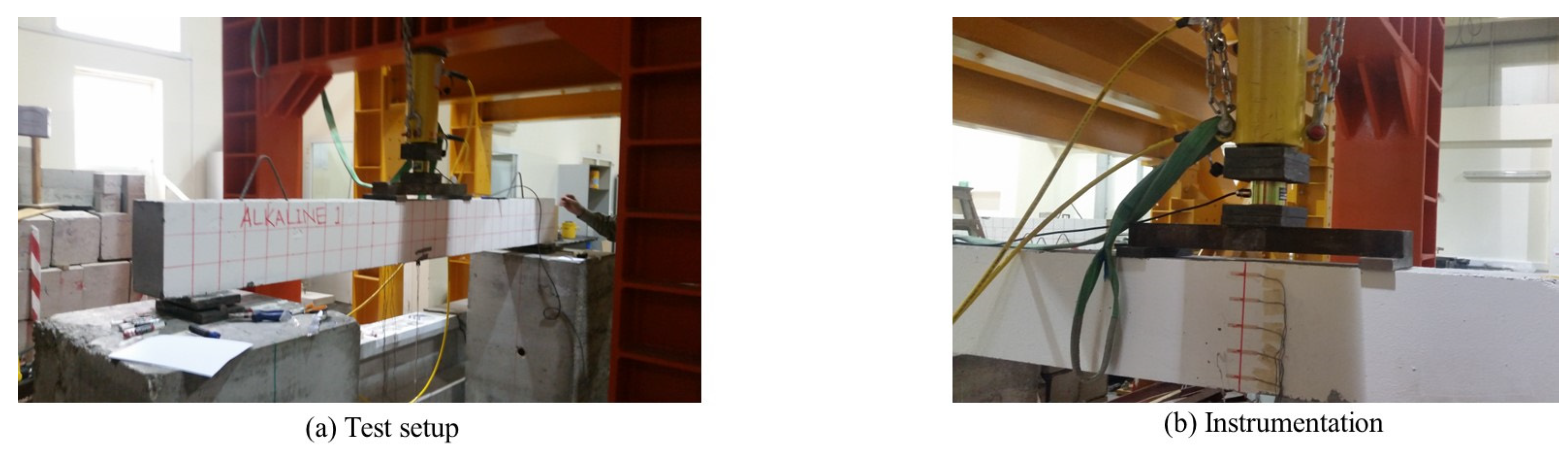
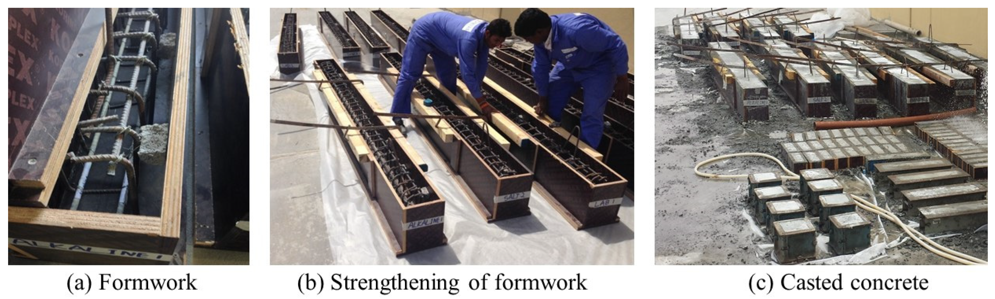
3. Experimental Program
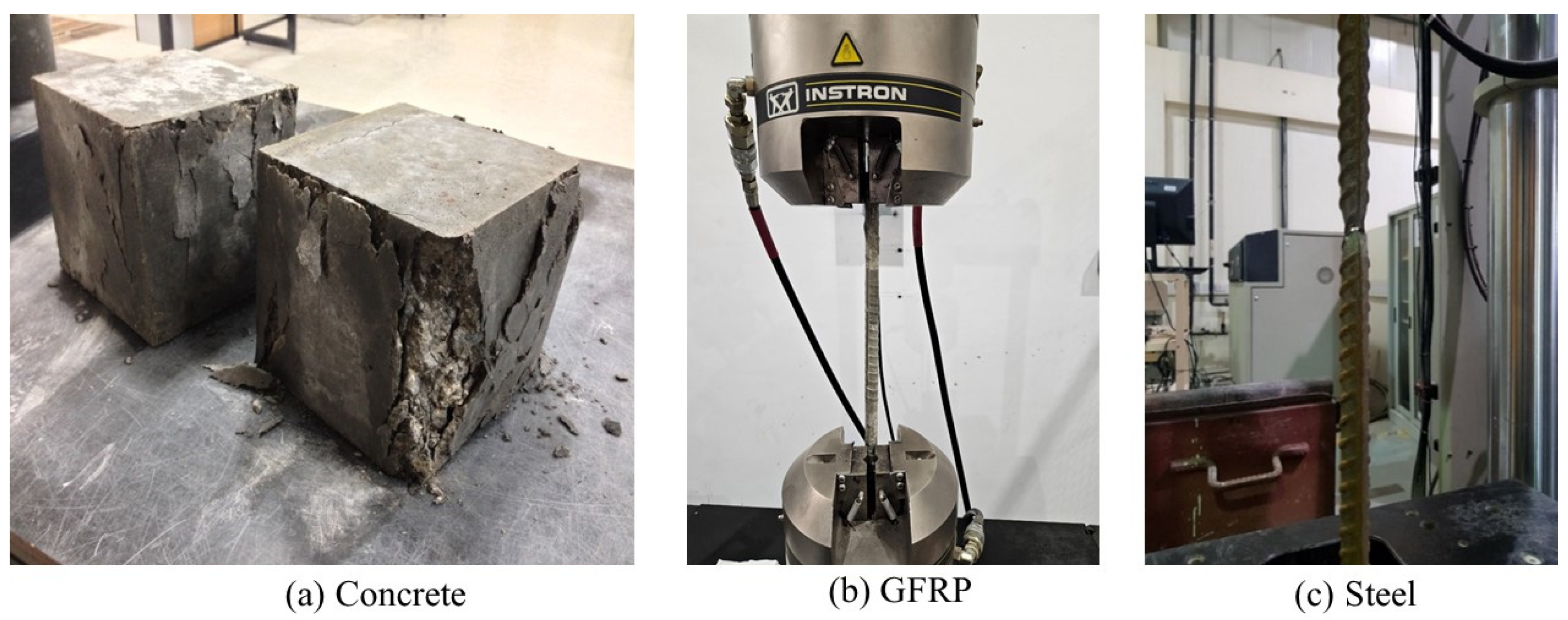
4. Materials and Methods
5. Results
5.1. Analysis of Experimental Findings
5.2. Theoretical Predictions
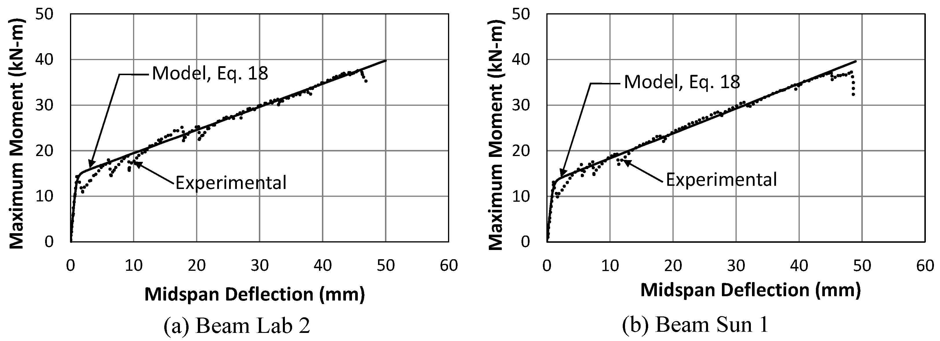
5.3. Modelling of the Entire Flexural Response
6. Conclusions
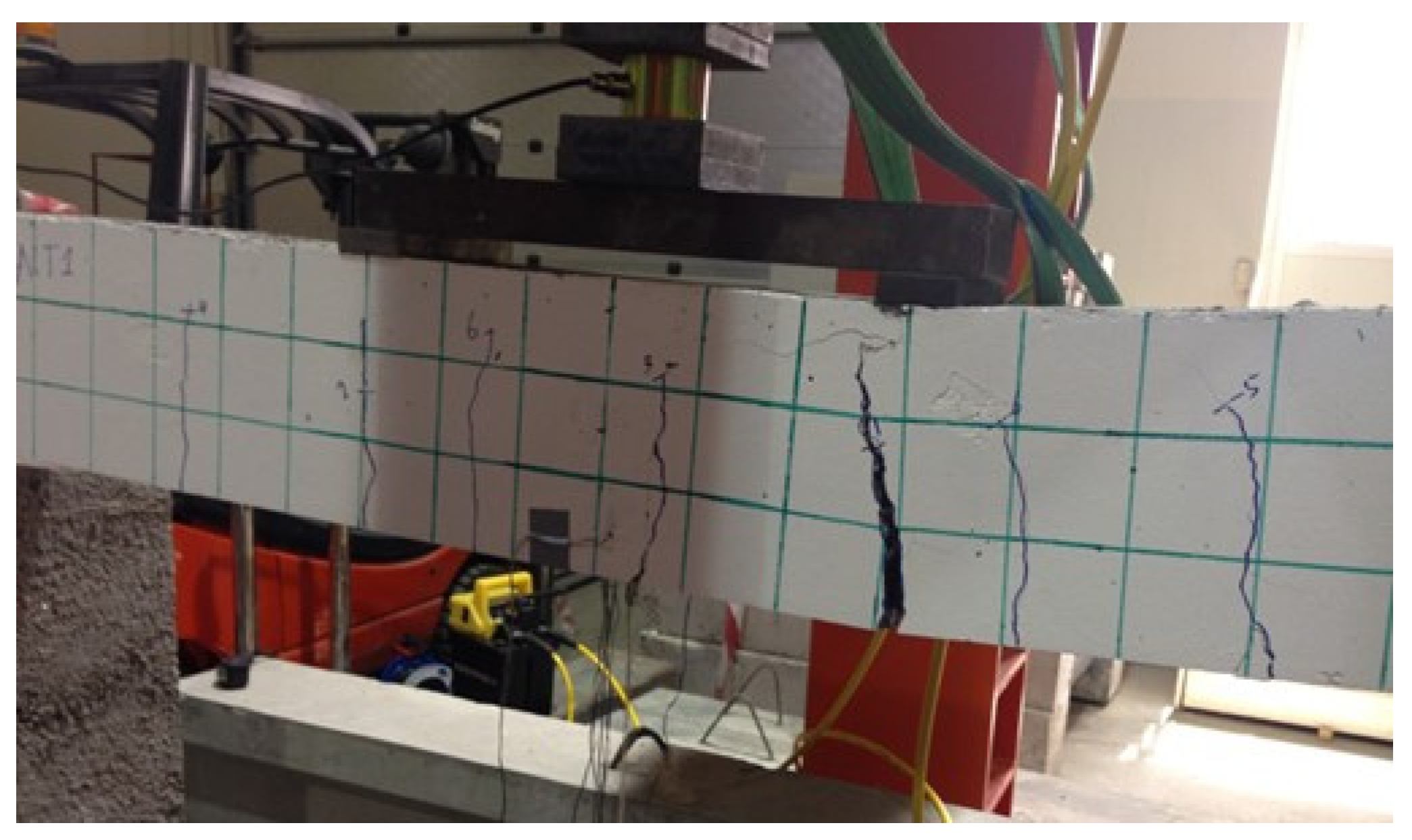
- Data from the strain gauges that were attached to the GFRP bars within the critical flexural region of the concrete beams confirmed the linear behavior of the embedded reinforcement with the increase in the applied load up to failure. No slippage due to bond failure between the surface of the GFRP bars and surrounding concrete was detected during the tests;
- Crack width records from the tests indicated the superior serviceability of the beams that contained composite rebars that were stored in a controlled environment and the inferior serviceability of the beams that contained rebars that were stored outdoors for an extended period of time prior to using them as reinforcement in concrete;
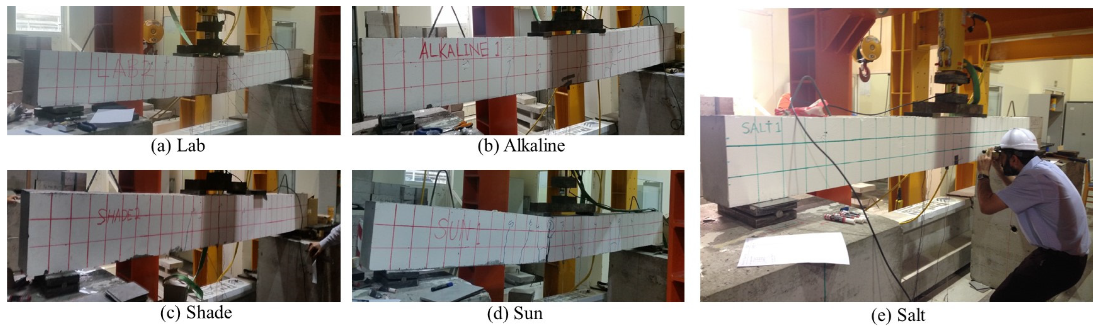
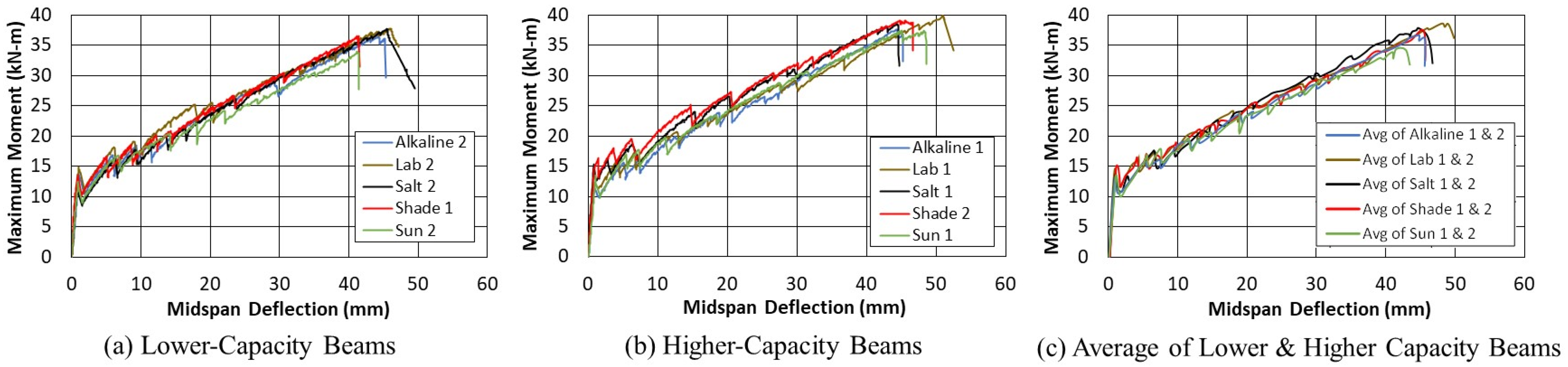
- The experimental test results showed that the moment capacity of the tested beams at ultimate was approximately 2.4–3.3 times the corresponding moment capacity at initial cracking, with the smallest ratios observed for the beams containing rebars that were exposed to an outdoor environment and the largest ratios for the control indoor beams. The flexural post-cracking stiffness was about 2.8–4.5% of the corresponding pre-cracking stiffness. The ductility index for the tested beams, measured as the deflection at ultimate to that at cracking, ranged between 2.9 and 4.16, with the higher value corresponding to one of the two control beams;
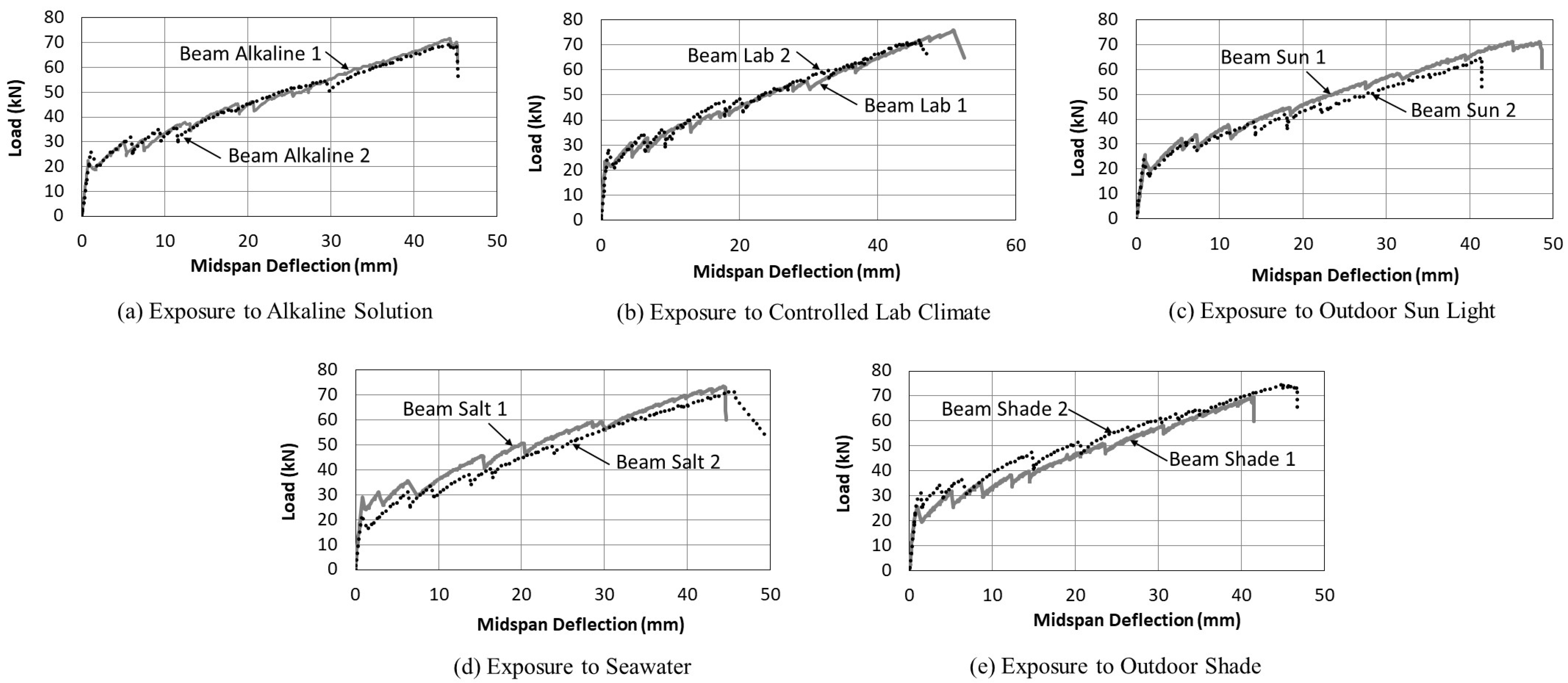
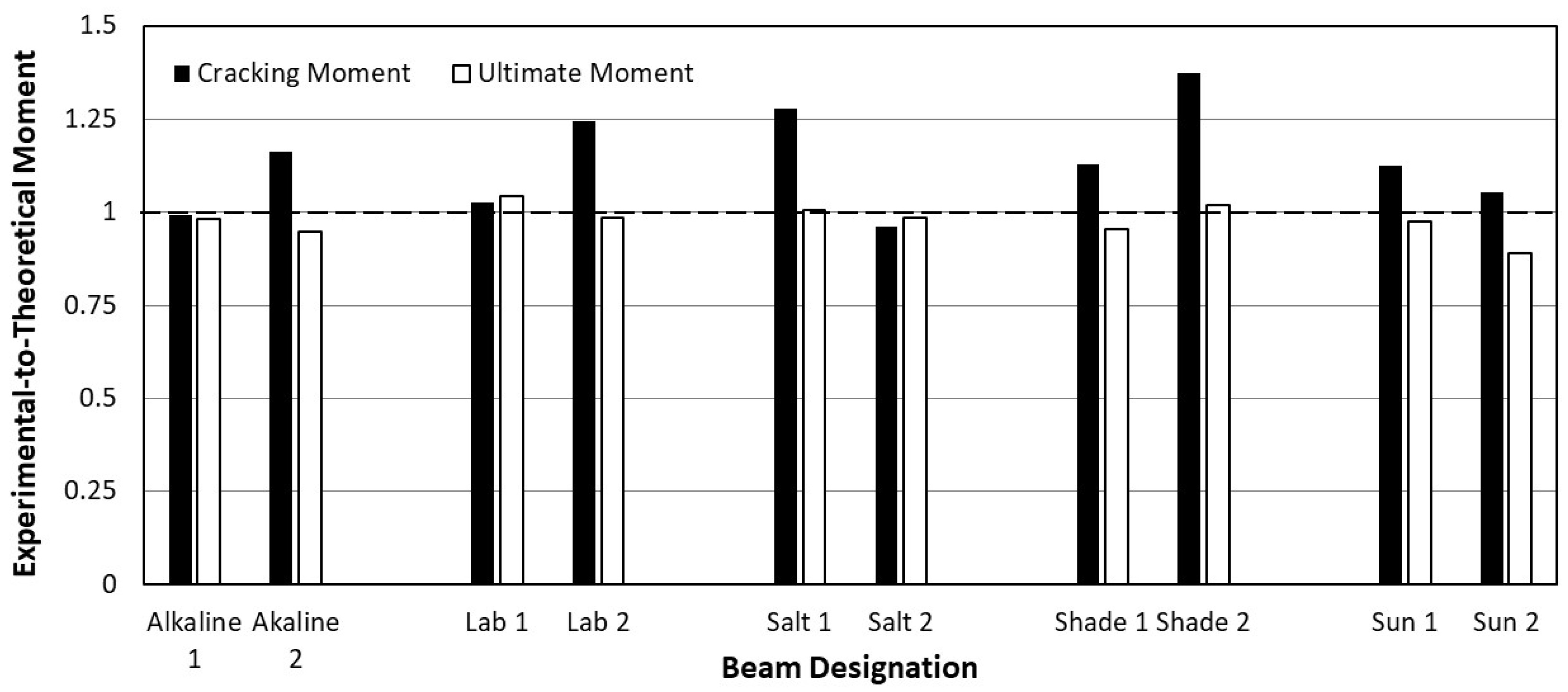
- GFRP bar exposure to an alkaline solution or outdoor direct sunlight slightly affected the cracking and ultimate moment capacities, reducing them by, respectively, 5% and 3% from the same parameters of the controlled indoor exposure. While the influence of GFRP bar exposure on the post-cracking stiffness of beams was minimal, it had a great effect on the pre-cracking stiffness, resulting in about a 25% reduction for the outdoor shade and sun environments. The largest effect of bar exposure on flexural ductility was due to exposure to the outdoor climate, for which reductions of 20% and 10% were observed for bars subjected to open air shade and sun, respectively;
- The predicted flexural strength at ultimate using the ACI 440 provisions gave comparable values when compared with the experimentally obtained results, with the difference between the two ranging between −4.2 to +12.6%. The cracking moment of the sections based on theoretical formulations was off the corresponding experimental findings by −4% to +28%;
- While the computed pre-cracking flexural stiffness of the considered beams compared reasonably well with the experimentally obtained values, the computed post-cracking flexural stiffness over-estimated the experimental values by 28–38%;
- A mathematical equation that envelopes the moment–deflection relationship for GFRP over-reinforced concrete beams is proposed. The equation requires information about two points on the curve, initial cracking and ultimate flexural conditions, and leads to close agreement with the experimental findings.
Author Contributions
Funding
Institutional Review Board Statement
Informed Consent Statement
Data Availability Statement
Acknowledgments
Conflicts of Interest
References
- Li, S.; Lv, H.; Huang, T.; Zhang, Z.; Yao, J.; Ni, X. Degradation of Reinforced Concrete Beams Subjected to Sustained Loading and Multi-Environmental Factors. Buildings 2022, 12, 1382. [Google Scholar] [CrossRef]
- Sbahieh, S.; Tahir, F.; Al-Ghamdi, S.G. Environmental and mechanical performance of different fiber reinforced polymers in beams. Mater. Today Proc. 2022, 62, 3548–3552. [Google Scholar] [CrossRef]
- Ji, X.-L.; Chen, L.-J.; Liang, K.; Pan, W.; Su, R.K.-L. A review on FRP bars and supplementary cementitious materials for the next generation of sustainable and durable construction materials. Constr. Build. Mater. 2023, 383, 131403. [Google Scholar] [CrossRef]
- Kinjawadekar, T.A.; Patil, S.; Nayak, G. A Critical Review on Glass Fiber-Reinforced Polymer Bars as Reinforcement in Flexural Members. J. Inst. Eng. (India) Ser. A 2023, 104, 501–516. [Google Scholar] [CrossRef]
- Kim, H.-Y.; Park, Y.-H.; You, Y.-J.; Moon, C.-K. Short-term durability test for GFRP rods under various environmental conditions. Compos. Struct. 2008, 83, 37–47. [Google Scholar] [CrossRef]
- Al-Salloum, Y.A.; El-Gamal, S.; Almusallam, T.; Alsayed, S.; Aqel, M. Effect of harsh environmental conditions on the tensile properties of GFRP bars. Compos. Part B Eng. 2012, 45, 835–844. [Google Scholar] [CrossRef]
- El-Hassan, H.; El Maaddawy, T. Microstructure Characteristics of GFRP Reinforcing Bars in Harsh Environment. Adv. Mater. Sci. Eng. 2019, 2019, 8053843. [Google Scholar] [CrossRef]
- Manalo, A.; Maranan, G.; Benmokrane, B.; Cousin, P.; Alajarmeh, O.; Ferdous, W.; Liang, R.; Hota, G. Comparative durability of GFRP composite reinforcing bars in concrete and in simulated concrete environments. Cem. Concr. Compos. 2020, 109, 103564. [Google Scholar] [CrossRef]
- Vizentin, C.; Glujić, D.; Špada, V. Effect of time-real marine environment exposure on the mechanical behavior of FRP composites. Sustainability 2021, 13, 9934. [Google Scholar] [CrossRef]
- Fergani, H.; Di Benedetti, M.; Oller, C.M.; Lynsdale, C.; Guadagnini, M. Durability and degradation mechanisms of GFRP reinforcement subjected to severe environments and sustained stress. Constr. Build. Mater. 2018, 170, 637–648. [Google Scholar] [CrossRef]
- Davalos, J.F.; Chen, Y.; Ray, I. Long-term durability prediction models for GFRP bars in concrete environment. J. Compos. Mater. 2011, 46, 1899–1914. [Google Scholar] [CrossRef]
- Gooranorimi, O.; Nanni, A. GFRP Reinforcement in Concrete after 15 Years of Service. J. Compos. Constr. 2017, 21, 04017024. [Google Scholar] [CrossRef]
- Arczewska, P.; Polak, M.A.; Penlidis, A. Degradation of glass fiber reinforced polymer (GFRP) bars in concrete environment. Constr. Build. Mater. 2021, 293, 123451. [Google Scholar] [CrossRef]
- Jin, Q.; Chen, P.; Gao, Y.; Du, A.; Liu, D.; Sun, L. Tensile Strength and Degradation of GFRP Bars under Combined Effects of Mechanical Load and Alkaline Solution. Materials 2020, 13, 3533. [Google Scholar] [CrossRef] [PubMed]
- Al-Tamimia, A.; Abed, F.H.; Al-Rahmani, A. Effects of harsh environmental exposures on the bond capacity between concrete and GFRP reinforcing bars. Adv. Concr. Constr. 2014, 2, 1–11. [Google Scholar] [CrossRef]
- Lu, C.; Yang, Y.; He, L. Mechanical and durability properties of GFRP bars exposed to aggressive solution environments. Sci. Eng. Compos. Mater. 2021, 28, 11–23. [Google Scholar] [CrossRef]
- Maranan, G.; Manalo, A.; Benmokrane, B.; Karunasena, W.; Mendis, P. Evaluation of the flexural strength and serviceability of geopolymer concrete beams reinforced with glass-fibre-reinforced polymer (GFRP) bars. Eng. Struct. 2015, 101, 529–541. [Google Scholar] [CrossRef]
- Nematzadeh, M.; Fallah-Valukolaee, S. Experimental and analytical investigation on structural behavior of two-layer fiber-reinforced concrete beams reinforced with steel and GFRP rebars. Constr. Build. Mater. 2021, 273, 121933. [Google Scholar] [CrossRef]
- Abbas, H.; Abadel, A.; Almusallam, T.; Al-Salloum, Y. Experimental and analytical study of flexural performance of concrete beams reinforced with hybrid of GFRP and steel rebars. Eng. Fail. Anal. 2022, 138, 106397. [Google Scholar] [CrossRef]
- Muhammad, M.A.; Ahmed, F.R. Evaluation of deflection and flexural performance of reinforced concrete beams with glass fiber reinforced polymer bars. Case Stud. Constr. Mater. 2023, 18, e01855. [Google Scholar] [CrossRef]
- Mohammed, A.A.; Muhammad, M.A.; Mohammed, B.K. Effect of PET waste fiber addition on flexural behavior of concrete beams reinforced with GFRP bars. Case Stud. Constr. Mater. 2023, 19, e02564. [Google Scholar] [CrossRef]
- Elangovan, G.; Rajanandhini, V. Flexural strength of Glass fiber reinforced polymer concrete beam with artificial Fine aggregate. Mater. Today Proc. 2022, 62, 1072–1077. [Google Scholar] [CrossRef]
- Farias, C.; Pessi, S.; Wanderlind, A.; Piva, J.H.; Pavei, E. Flexural behavior of concrete beams reinforced with glass fiber reinforced polymer and steel bars. Rev. De La Constr. 2022, 21, 506–522. [Google Scholar] [CrossRef]
- Ali, N.K.S.; Mahfouz, S.Y.; Amer, N.H. Flexural Response of Concrete Beams Reinforced with Steel and Fiber Reinforced Polymers. Buildings 2023, 13, 374. [Google Scholar] [CrossRef]
- Gouda, O.; Asadian, A.; Galal, K. Flexural and Serviceability Behavior of Concrete Beams Reinforced with Ribbed GFRP Bars. J. Compos. Constr. 2022, 26, 04022064. [Google Scholar] [CrossRef]
- Hassan, H.F.; Medhlom, M.K.; Ahmed, A.S.; Al-Dahlaki, M.H. Flexural performance of concrete beams reinforced by gfrp bars and strengthened by cfrp sheets. Case Stud. Constr. Mater. 2020, 13, e00417. [Google Scholar] [CrossRef]
- Abed, F.; ElMesalami, N. Effect of Harsh Environmental Conditions on the Bond-Dependent Coefficient of GFRP Bars in Concrete Beams. In Proceedings of the 2019 Advances in Science and Engineering Technology International Conferences (ASET), Dubai, United Arab Emirates, 26–28 March 2019; pp. 1–5. [Google Scholar]
- ACI 440.1R-15; ACI. Guide for the Design and Construction of Structural Concrete Reinforced with Fiber-Reinforced Polymer (FRP) Bars. American Concrete Institute: Detroit, MI, USA, 2021; 88p.
- Bischoff, P.H. Reevaluation of Deflection Prediction for Concrete Beams Reinforced with Steel and Fiber Reinforced Polymer Bars. J. Struct. Eng. 2005, 131, 752–767. [Google Scholar] [CrossRef]
- Mattock, A.H. Flexural Strength of Prestressed Concrete Sections by Programmable Calculator. PCI J. 1979, 24, 32–54. [Google Scholar] [CrossRef]


| Beams Label | Exposure Condition |
|---|---|
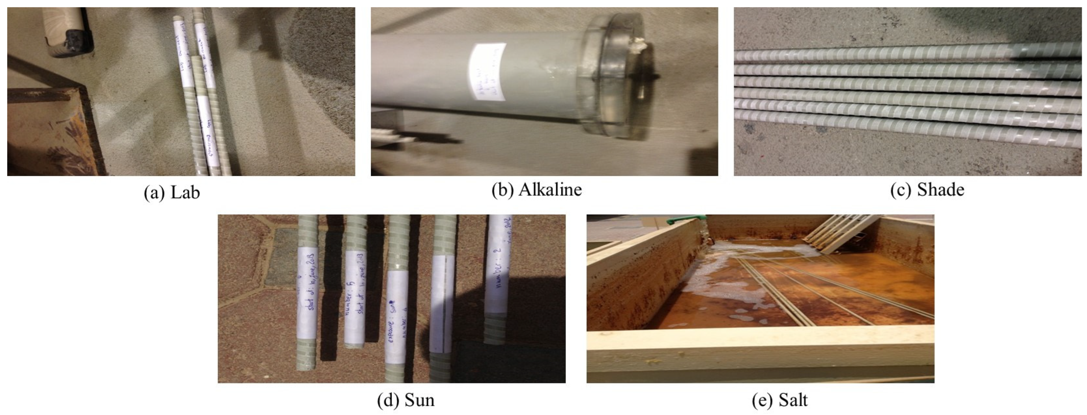
| Lab 1 and Lab 2 | Indoor controlled climate at 22–25 °C |
| Sun 1 and Sun 2 | Outdoor direct sun light (9–48 °C) |
| Shade 1 and Shade 2 | Outdoor in the shade (9–48 °C) |
| Alkaline 1 and Alkaline 2 | Solution having pH value of 12.99 pH |
| Salt 1 and Salt 2 | Salinity between 38 and 41 g/kg |
| Weather Condition | June | July | August | September | October | November | December |
|---|---|---|---|---|---|---|---|
| Maximum Temperature (°C) | 35–43 | 39–48 | 38–44 | 35–43 | 32–40 | 25–37 | 19–31 |
| Minimum Temperature (°C) | 23–30 | 29–34 | 29–34 | 25–31 | 21–27 | 17–24 | 9–20 |
| Range of Wind Speed (km/h) | 0–29 | 0–35 | 0–45 | 0–48 | 0–29 | 0–37 | 0–35 |
| Constituents | Amount (kg per m3 of Concrete) |
|---|---|
| Ordinary Portland Cement | 425 |
| Microsilica | 25 |
| Water | 151 |
| Crushed Washed Sand | 290 |
| Red Dune Sand | 390 |
| Coarse Aggregate (Maximum size = 20 mm) | 1180 |
| Additives (MegaFlow 2000 and MegaddVE) | 9 |
| Flexural Parameter | Alkal. 1 | Alkal. 2 | Lab 1 | Lab 2 | Salt 1 | Salt 2 | Shade 1 | Shade 2 | Sun 1 | Sun 2 |
|---|---|---|---|---|---|---|---|---|---|---|
| Cracking Moment (kN·m) | 11.85 | 13.91 | 12.26 | 14.87 | 15.28 | 11.49 | 13.48 | 16.42 | 13.45 | 12.57 |
| Pre-Cracking Stiffness (kN·m/m) | 14,484 | 13,366 | 19,724 | 14,899 | 18,016 | 15,143 | 14,460 | 11,692 | 12,963 | 13,556 |
| Ultimate Moment (kN·m) | 37.57 | 36.37 | 39.93 | 37.76 | 38.59 | 37.70 | 36.55 | 39.09 | 37.40 | 34.04 |
| Post-Cracking Stiffness (kN·m/m) | 593 | 520 | 550 | 508 | 536 | 587 | 569 | 522 | 545 | 534 |
| Ductility Index () | 3.73 | 3.18 | 4.16 | 3.10 | 2.90 | 3.95 | 3.08 | 2.73 | 3.34 | 3.27 |
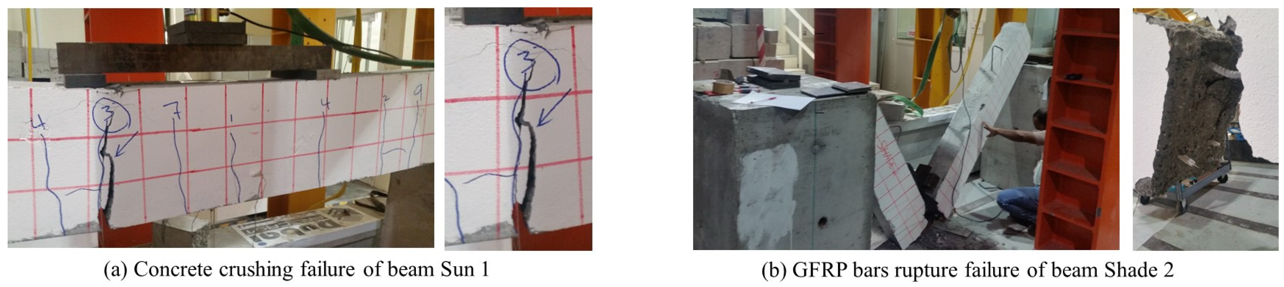
| Flexural Mode of Failure 1 | CC | CC | CC | CC | CC | CC | CC | BF | CC | BF |
| Average Flexural Parameter | Alkaline | Lab | Salt | Shade | Sun |
|---|---|---|---|---|---|
| Cracking Moment (kN·m) | 12.88 | 13.57 | 13.38 | 14.95 | 13.01 |
| Pre-Cracking Stiffness (kN·m/m) | 14,107 | 17,312 | 16,580 | 13,076 | 13,260 |
| Ultimate Moment (kN·m) | 36.97 | 38.84 | 38.14 | 37.82 | 35.72 |
| Post-Cracking Stiffness (kN·m/m) | 557 | 529 | 562 | 546 | 540 |
| Ductility Index () | 3.45 | 3.62 | 3.43 | 2.90 | 3.31 |
Disclaimer/Publisher’s Note: The statements, opinions and data contained in all publications are solely those of the individual author(s) and contributor(s) and not of MDPI and/or the editor(s). MDPI and/or the editor(s) disclaim responsibility for any injury to people or property resulting from any ideas, methods, instructions or products referred to in the content. |
© 2024 by the authors. Licensee MDPI, Basel, Switzerland. This article is an open access article distributed under the terms and conditions of the Creative Commons Attribution (CC BY) license (https://creativecommons.org/licenses/by/4.0/).
Share and Cite
Tabsh, S.W.; Tamimi, A.; El-Emam, M.; Zandavi, A. Effect of Rebar Harsh Storage Conditions on the Flexural Behavior of Glass FRP Concrete. Sustainability 2024, 16, 1944. https://doi.org/10.3390/su16051944
Tabsh SW, Tamimi A, El-Emam M, Zandavi A. Effect of Rebar Harsh Storage Conditions on the Flexural Behavior of Glass FRP Concrete. Sustainability. 2024; 16(5):1944. https://doi.org/10.3390/su16051944
Chicago/Turabian StyleTabsh, Sami W., Adil Tamimi, Magdi El-Emam, and Ali Zandavi. 2024. "Effect of Rebar Harsh Storage Conditions on the Flexural Behavior of Glass FRP Concrete" Sustainability 16, no. 5: 1944. https://doi.org/10.3390/su16051944
APA StyleTabsh, S. W., Tamimi, A., El-Emam, M., & Zandavi, A. (2024). Effect of Rebar Harsh Storage Conditions on the Flexural Behavior of Glass FRP Concrete. Sustainability, 16(5), 1944. https://doi.org/10.3390/su16051944