
Integrating BIM-LCA to Enhance Sustainability Assessments of Constructions

 ,
,  ,
, 
Abstract
1. Introduction
2. Materials and Methods
2.1. Objectives of the Study
2.2. Software and BIM Tools Utilized
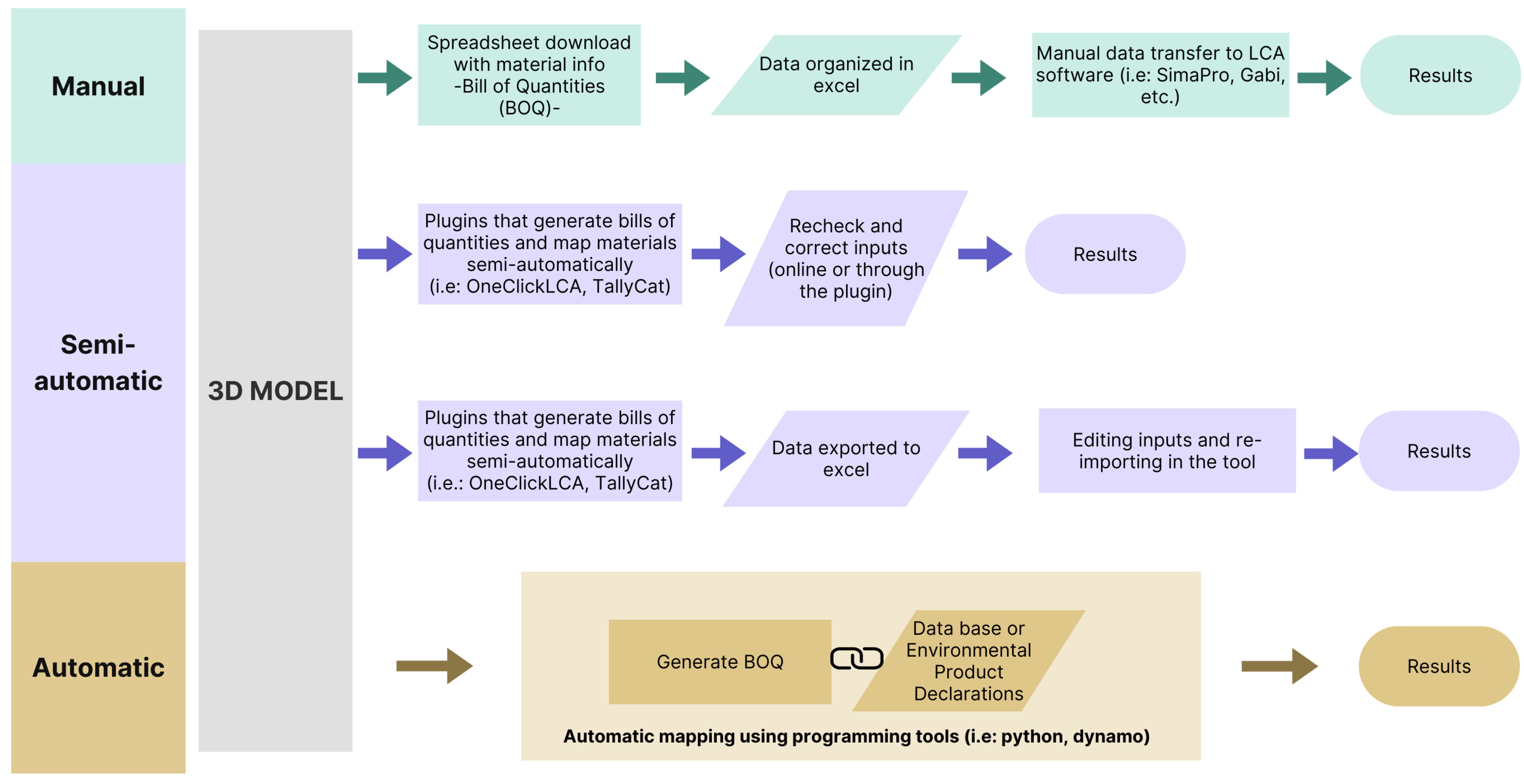
2.3. Process Map
2.4. Exchange Information Requirement (EIR)
- Building type;
- Area;
- Location;
- Estimated energy consumption.
- Description of elements/materials;
- Category, family, type;
- Dimensions and quantities;
- GUID.
2.5. Life-Cycle Assessment
Scope of Study and System Boundaries
- A1–A3 (Raw material extraction, transportation, and production): Included. Automatically attributed when an EPD is applied to each material dataset.
- A4 (Transportation): Included. Distances were manually inserted based on the ones informed in the EPD.
- A5 (Construction): Excluded in this study.
- B1 (Use): Excluded. (There is no specific field in OCL for inserting this information.)
- B2 (Maintenance): Excluded. (There is no specific field in OCL for inserting this information, but the field to inform repairment can be utilized.)
- B3 (Repair): Excluded. There is a specific field to be filled in to communicate annual repairs given to a product or material. This value is given as a percentage. Therefore, if there is a window over a total of ten in a building to be repaired in a year, the number to be provided is 2%. In this study, these blank spaces were left empty for both of the projects (before and after).
- B4–B5 (Replacement and refurbishment): Included. OCL automatically defines the service life of products and materials, enabling the automatic calculation of their impacts. The lifespan of the building is set to the standard 60 years established by EN 15978 [24] and EN 15804 [23]. Considering that some materials have shorter lifespans, the automatically defined lifespan provided by the software is adopted. Similarly, default values for waste, transportation distance, and end-of-life processing of materials configured by the system were adhered to. It is crucial to acknowledge that information on the longevity of products is often scarce; in many cases, even the manufacturers may not have precise data on the durability of their products. Therefore, the necessity for accurate and comprehensive EPD becomes evident, not only for selecting appropriate datasets for specific projects, but also to ensure that the life expectancies of products are accurately reported. This approach is vital for enhancing decision-making processes in sustainable construction, aligning with broader goals of environmental, social, and economic impact mitigation.
- B6 (Operational energy use): Included (demanded by OCL). This is calculated with Insight and Green Building Studio (GBS); to perform the carbon-emissions analysis for the building, OCL requires the estimated annual energy consumption and the lifespan of the building. For defining the building’s energy consumption, Revit® is used in conjunction with the GBS [25] and Insight [26] tools. The calculated annual energy consumption is 36,711 kWh/year for the existing construction and 30,744 kWh/year for the proposed version.
- B7 (Operational water use): Excluded.
- C1 (Demolition): Excluded.
- C2 (Transport): Excluded.
- C3–C4 (Waste processing and disposal): Included. OCL allows the user to define the EOL of the products. The options vary between ‘do nothing’, ‘reuse’, ‘backfilling and landfilling’ for inert materials, and ‘recycling’. The program suggests specific EOL depending on the EPD selected for the material. Concrete, mortar, and bricks, for example, are automatically set to be crushed and used as aggregate in subbase layers.
- D (Re-use, recovery and recycling potential): Included. In OCL it is possible to define whether the material is to be reused. This field is used to model the project after renovation, since most of the elements of the building were maintained.
3. Interoperability between Revit® and OneClick LCA
3.1. Nomenclature
- Which language should be adopted? Portuguese or English?
- What level of detail should be adopted in the material labels?
- What information needs to be visible and immediately comprehensible?
- Sequence of information within the material property?
- Class: WALL
- Family: WALL_EXT_E
- Type: WALL_EXT_CERAMIC_E
- Material: CERAMICBRICK_HOLLOW_25_E
3.2. Step-by-Step
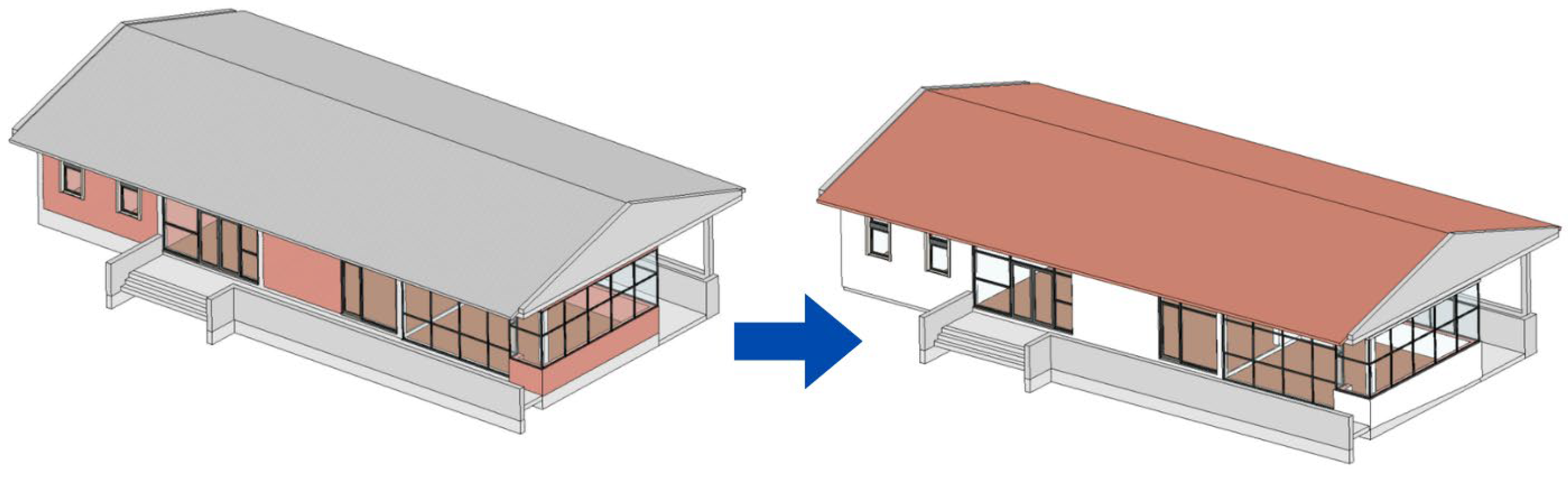
3.3. Proposed Phase
- Ceilings: Only in the ‘Proposed’ version.
- Curtain Panels: Modified.
- Curtain Wall Mullions:
- ○
- Casings: Retained.
- ○
- Frames: Modified.
- Doors:
- ○
- Interior: Retained but sanded, painted, and varnished.
- ○
- Exterior: Modified.
- Walls:
- ○
- Interior: Retained, but painted and refurbished (bathroom tiles).
- ○
- Exterior: Retained, but painted and refurbished (external insulation system).
- Floors: Modified.
- Roof: Modified.
- Stairs: Retained.
- Structural Elements: Retained.
- Windows: Modified.
- Export Revit® data to OCL (plugin and online).
- Map elements in the proposed phase (employing low-impact datasets for refurbished materials).
- Download the Excel file after mapping.
- Manually edit the comment field to classify existing, added, proposed, and refurbished elements.
- Filter existing elements to determine which datasets used in the existing phase should remain unchanged.
- Map the existing phase using datasets that might not necessarily be correct (opting for relatively higher impact datasets for material fields in the existing phase to be altered).
- Download the Excel file after this second mapping.
- Edit the comment field again to identify existing and refurbished elements, referring to the Excel file from the proposed phase.
- Transfer unchanged datasets from the proposed to the existing phase.
- Upload both Excel files to the online version of OCL (existing and proposed phases).
- Examine the results in the online version of OCL.
4. Results and Discussions
Challenges and Best Practices
5. Conclusions
Supplementary Materials
Author Contributions
Funding
Institutional Review Board Statement
Informed Consent Statement
Data Availability Statement
Acknowledgments
Conflicts of Interest
References
- Mora, T.D.; Bolzonello, E.; Cavalliere, C.; Peron, F. Key Parameters Featuring BIM-LCA Integration in Buildings: A Practical Review of the Current Trends. Sustainability 2020, 12, 7182. [Google Scholar] [CrossRef]
- United Nations. Sustainable Development Goals. Available online: https://sustainabledevelopment.un.org/?menu=1300 (accessed on 10 March 2020).
- ISO 14040; Environmental Management—Life Cycle Assessment—Principles and Framework. International Organization for Standardization: Geneva, Switzerland, 2006.
- Bovea, M.D.; Powell, J.C. Developments in life cycle assessment applied to evaluate the environmental performance of construction and demolition wastes. Waste Manag. 2016, 50, 151–172. [Google Scholar] [CrossRef] [PubMed]
- Oreto, C.; Biancardo, S.A.; Abbondati, F.; Veropalumbo, R. Leveraging Infrastructure BIM for Life-Cycle-Based Sustainable Road Pavement Management. Materials 2023, 16, 1047. [Google Scholar] [CrossRef] [PubMed]
- Boje, C.; Menacho, J.H.; Marvuglia, A.; Benetto, E.; Kubicki, S.; Schaubroeck, T.; Gutiérrez, T.N. A framework using BIM and digital twins in facilitating LCSA for buildings. J. Build. Eng. 2023, 76, 1072332. [Google Scholar] [CrossRef]
- EN ISO 19650-1; Organization and Digitalization of Information about Buildings and Civil Engineering Worls, Including Building Information Modelling (BIM): Part 1: Concepts and Principles. International Organization for Standardization: Geneva, Switzerland, 2018.
- EN ISO 19650-2; Organization and Digitalization of Information about Buildings and Civil Engineering Worls, Including Building Information Modelling (BIM): Part 2: Delivery Phase of the Assets. International Organization for Standardization: Geneva, Switzerland, 2018.
- Obrecht, T.P.; Röck, M.; Hoxha, E.; Passer, A. BIM and LCA Integration: A Systematic Literature Review. Sustainability 2020, 12, 5534. [Google Scholar] [CrossRef]
- Safari, K.; AzariJafari, H. Challenges and opportunities for integrating BIM and LCA: Methodological choices and framework development. Sustain. Cities Soc. 2021, 67, 10272. [Google Scholar] [CrossRef]
- Soust-Verdaguer, B.; Llatas, C.; García-Martínez, A. Critical review of bim-based LCA method to buildings. Energy Build. 2017, 136, 110–120. [Google Scholar] [CrossRef]
- Basbagill, J.; Flager, F.; Lepech, M.; Fischer, M. Application of life-cycle assessment to early stage building design for reduced embodied environmental impacts. Build. Environ. 2013, 60, 81–92. [Google Scholar] [CrossRef]
- Llatas, C.; Soust-Verdaguer, B.; Passer, A. Implementing Life Cycle Sustainability Assessment during design stages in Building Information Modelling: From systematic literature review to a methodological approach. Build. Environ. 2020, 182, 107164. [Google Scholar] [CrossRef]
- Crippa, J.; Araujo, A.M.; Bem, D.; Ugaya, C.M.; Scheer, S. A systematic review of BIM usage for life cycle impact assessment. BEPAM 2020, 10, 603–618. [Google Scholar] [CrossRef]
- Hollberg, A.; Genova, G.; Habert, G. Evaluation of BIM-based LCA results for building design. Autom. Constr. 2020, 109, 102972. [Google Scholar] [CrossRef]
- Najjar, M.; Figueiredo, K.; Palumbo, M.; Haddad, A. Integration of BIM and LCA: Evaluating the environmental impacts of building materials at an early stage of designing a typical office building. J. Build. Eng. 2017, 14, 115–126. [Google Scholar] [CrossRef]
- Tam, V.W.; Zhou, Y.; Illankoon, C.; Le, K.N. A critical review on BIM and LCA integration using the ISO 14040 framework. Build. Environ. 2022, 213, 108865. [Google Scholar] [CrossRef]
- Autodesk, Software Revit®, Version 2022, USA. Available online: https://www.autodesk.com/products/revit/overview?term=1-YEAR&tab=subscription (accessed on 24 November 2023).
- One Click LCA. One Click LCA: Life Cycle Assessment. 2023. Available online: https://www.oneclicklca.com/ (accessed on 24 November 2023).
- Building Transparency, KT Innovations, Thinkstep, and Autodesk. Tally. 2023. Available online: https://choosetally.com/contact/ (accessed on 24 November 2023).
- BS EN 17412-1:2020; Building Information Modelling—Level of Information Need: Part 1: Concepts and Principles. International Organization for Standardization: Geneva, Switzerland, 2020.
- One Click LCA. Building Information Model Creation Guidelines. Available online: https://www.oneclicklca.com/bim-creation-guidelines-for-model-use/ (accessed on 1 July 2023).
- EN 15804; Sustainability of Construction Works—Environmental Product Declarations—Core Rules for the Product Category of Construction Products. International Organization for Standardization: Geneva, Switzerland, 2018.
- EN 15978; Sustainability of Buildings—Evaluation of Environmental Quality of Buildings—Calculation Method. International Organization for Standardization: Geneva, Switzerland, 2011.
- Autodesk. Green Building Studio. 2023. Available online: https://gbs.autodesk.com/GBS/?redirectUrl=%2FGBS%2FProject (accessed on 6 November 2023).
- Autodesk. Insight. 2023. Available online: https://insight.autodesk.com/oneenergy (accessed on 27 October 2023).
- Masson, S. Short Guide to BIM Modelling for LCA Automation. Available online: https://oneclicklca.zendesk.com/hc/en-us/articles/360015040039-Short-Guide-to-BIM-Modelling-for-LCA-automation (accessed on 12 November 2023).
- Leiden University. CML Database. Available online: https://www.universiteitleiden.nl/en/science/environmental-sciences/tools-and-data#CMLCA (accessed on 20 October 2023).
- I Am Consultoria. SECClasS: Sustainability Enhanced Construction Classification System. 2021. Available online: https://secclass.pt/pesquisa/ (accessed on 15 November 2023).
- UK Government. Construction Operations Building Information Exchange (COBie): NBS. 2011. Available online: https://www.thenbs.com/knowledge/what-is-cobie#:~:text=Construction%20Operations%20Building%20Information%20Exchange,as%20distinct%20from%20geometric%20information (accessed on 5 August 2023).


Disclaimer/Publisher’s Note: The statements, opinions and data contained in all publications are solely those of the individual author(s) and contributor(s) and not of MDPI and/or the editor(s). MDPI and/or the editor(s) disclaim responsibility for any injury to people or property resulting from any ideas, methods, instructions or products referred to in the content. |
© 2024 by the authors. Licensee MDPI, Basel, Switzerland. This article is an open access article distributed under the terms and conditions of the Creative Commons Attribution (CC BY) license (https://creativecommons.org/licenses/by/4.0/).
Share and Cite
Lima, M.S.S.; Duarte, S.; Exenberger, H.; Fröch, G.; Flora, M. Integrating BIM-LCA to Enhance Sustainability Assessments of Constructions. Sustainability 2024, 16, 1172. https://doi.org/10.3390/su16031172
Lima MSS, Duarte S, Exenberger H, Fröch G, Flora M. Integrating BIM-LCA to Enhance Sustainability Assessments of Constructions. Sustainability. 2024; 16(3):1172. https://doi.org/10.3390/su16031172
Chicago/Turabian StyleLima, Mayara S. Siverio, Susana Duarte, Hans Exenberger, Georg Fröch, and Matthias Flora. 2024. "Integrating BIM-LCA to Enhance Sustainability Assessments of Constructions" Sustainability 16, no. 3: 1172. https://doi.org/10.3390/su16031172
APA StyleLima, M. S. S., Duarte, S., Exenberger, H., Fröch, G., & Flora, M. (2024). Integrating BIM-LCA to Enhance Sustainability Assessments of Constructions. Sustainability, 16(3), 1172. https://doi.org/10.3390/su16031172