Article

Fuzzy Logic-Based Smart Control of Wind Energy Conversion System Using Cascaded Doubly Fed Induction Generator

1
Electrical Engineering Department, Faculty of Sciences and Applied Sciences, University of Bouira, Bouira 10000, Algeria
2
Electrical Systems Engineering Department, University of Boumerdes, Frantz Fanon City, Boumerdes 35000, Algeria
3
Research Center in Industrial Technologies—CRTI, P.O. Box 64, Algiers 16014, Algeria
4
Department of Electrical Engineering, Hassiba Benbouali University, Chlef 02180, Algeria
*
Author to whom correspondence should be addressed.
Sustainability 2024, 16(21), 9333; https://doi.org/10.3390/su16219333
Submission received: 1 September 2024 / Revised: 13 October 2024 / Accepted: 21 October 2024 / Published: 27 October 2024

Abstract

:
This paper introduces a robust system designed to effectively manage and enhance the electrical output of a Wind Energy Conversion System (WECS) using a Cascaded Doubly Fed Induction Generator (CDFIG) connected to a power grid. The solution that was investigated is the use of a CDFIG that is based on a variable-speed wind power conversion chain. It comprises the electrical and mechanical connection of two DFIGs through their rotors. The originality of this paper lies in the innovative application of a fuzzy logic controller (FLC) in combination with a CDFIG for a WECS. To demonstrate that this novel configuration enhances control precision and performance in WECSs, we conducted a comparison of three different controllers: a proportional–integral (PI) controller, a fractional PID (FPID) controller, and a fuzzy logic controller (FLC). The results highlight the potential of the proposed system in optimizing power generation and improving overall system stability. It turns out that, according to the first results, the FLC performed optimally in terms of tracking and rejecting disturbances. In terms of peak overshoot for power and torque, the findings indicate that the proposed FLC-based technique (3.8639% and 6.9401%) outperforms that of the FOPID (11.2458% and 10.9654%) and PI controllers (11.4219% and 11.0712%), respectively. These results demonstrate the superior performance of the FLC in reducing overshoot, providing better control stability for both power and torque. In terms of rise time, the findings show that all controllers perform similarly for both power and torque. However, the FLC demonstrates superior performance with a rise time of 0.0016 s for both power and torque, compared to the FOPID (1.9999 s and 1.9999 s) and PI (0.0250 s and 0.0247 s) controllers. This highlights the FLC’s enhanced responsiveness in controlling power and torque. In terms of settling time, all three controllers have almost the same performance of 1.9999. An examination of total harmonic distortion (THD) was also employed to validate the superiority of the FLC. In terms of power quality, the findings prove that a WECS based on an FLC (0.93%) has a smaller total harmonic distortion (THD) compared to that of the FOPID (1.21%) and PI (1.51%) controllers. This system solves the problem by removing the requirement for sliding ring–brush contact. Through the utilization of the MATLAB/Simulink environment, the effectiveness of this control and energy management approach was evaluated, thereby demonstrating its capacity to fulfill the objectives that were set.

1. Introduction

The production of Wind Energy Conversion Systems (WECSs) reduces reliance on fossil fuels, leading to decreased greenhouse gas emissions and minimizing negative environmental impacts. By effectively harnessing natural wind resources, WECSs contribute to long-term energy sustainability and help mitigate climate change [1,2]. Additionally, their ability to operate in grid-connected systems makes them a highly viable option for sustainable energy transitions globally, positioning WECSs as one of the best choices for clean energy generation [2]. Several countries, including China, have expressed strong interest in harnessing clean and renewable energy sources, as these technologies can play a critical role in supporting China’s energy transition and can be used for the aim of contributing significantly to China’s goals of reaching the carbon peak by 2030 and achieving carbon neutrality by 2060 [3].
The introduction of renewable energies, namely wind energy, into the power grid poses significant difficulties in terms of management and optimization. Wind Energy Conversion Systems (WECSs) are challenging to manage because they are subject to uncertainties and variables caused by changing weather conditions [4,5,6,7,8]. Power control is crucial for effectively integrating WECSs into smart and traditional grids, ensuring stability, reliability, and optimal electrical energy utilization. Due to the unpredictable characteristics of wind, it is crucial to control the energy generation of wind turbines in order to ensure constant and effective incorporation into the electrical grid. Modern power control techniques prioritize the optimization of energy generation while reducing disruptions in the electrical grid, such as fluctuations in frequency and voltage [9,10,11]. Recent approaches involve the utilization of sophisticated techniques like fuzzy logic, predictive controllers, and machine learning algorithms to improve the robustness and effectiveness of power control. These strategies enable improved adjustment to fluctuating wind conditions and a more accurate control of wind energy integration into the power system [12,13,14,15,16,17].
Fuzzy controllers have emerged as an effective solution to improve the efficiency and stability of wind energy management systems [18,19,20,21,22]. FL controllers are being used more and more in wind power conversion systems to make them work better and more efficiently. FL controllers are great at dealing with the highly unpredictable and nonlinear behavior of wind. They do not need exact mathematical models, which are often hard to understand or do not work well in the real world, so they can adapt to changing wind speeds and directions [12,18].
In the literature, various papers address the control of WECSs, focusing on various aspects such as machine-side converters, grid-side converters, and pitch control strategies. The fuzzy logic controller (FLC) proposed in [23] generates the rotor voltages necessary to ensure that the active and reactive power in the WECS achieve their target reference values. In this case, fuzzy controllers frequently call for modifications that are quite fine.
The study in [24] presents a control law that combines sliding mode control and a single-input FLC to effectively and efficiently control a static synchronous compensator, enhancing both its performance and stability. The goal is to enhance the voltage profile and stability of an asynchronous WECS, even in the presence of wind speed and load fluctuations. However, an attractive choice is to experiment with an alternative form of FLCs, specifically ones that modify the PI reference value. In [25], an adaptive controller that is based on the principle of fuzzy logic is proposed in order to limit the extracted power at its rated value while simultaneously enhancing its quality. Additionally, the pitch angle is adjusted in order to alleviate the loads that are applied to the turbine and the drive train when they are operating under full load conditions. In [26], a model for Load Frequency Control (LFC) is given, which combines the economic dispatching control with the frequency control problem. The need for frequency stability is crucial in both the short-term and long-term operation of power systems. In [27], the suggested LFC model examines the role of hydro-turbines in power systems with abundant wind energy. It also seeks to understand how hydro-turbines contribute to the secondary frequency control scheme using a PID controller. Other researchers [28] aim to demonstrate the superiority of the adaptive PID controller with an FCL loop in a six-area power system associated with renewable energy sources. Current studies have additionally concentrated on comprehending the function of energy storage systems (ESSs), together with innovative control methods, in regulating the frequency of power systems mostly powered by wind. Using the cascaded dual-FLC strategy, a robust and adaptive energy management system was developed in [29] with the purpose of mitigating disturbances that were caused by varied solar irradiation, fluctuating wind speed, and even unexpected fluctuations in load. To achieve more stability, the suggested algorithm is able to govern the functioning of batteries, the mode of the microgrid, and the management of the load. In [30], an adaptive fuzzy logic controller is proposed as a control system designed to maximize power output from a WECS equipped with a permanent magnet synchronous generator. An excessive overshooting of the results is observed whenever there is a sudden shift in the references. A novel single-input variable (FLC) technique is proposed in [31] for a WT-driven doubly fed induction generator (DFIG) that is equipped with a battery energy storage system and operates in autonomous mode. The fact that this type of command is dependent on the internal properties of the system makes it a fragile command. In [32], there is a lack of a comparison study for the purpose of validating the results of the control and administration of an energy conversion system within a microgrid setup that includes numerous renewable energy sources and a storage system.
In the literature related to Brushless Double-Fed Induction Generators (BDFIGs), we can find several control techniques [33,34,35,36,37,38]. In [33], H. Huerta et al. explore a Hamiltonian model for controlling a BDFIG using sliding mode control (SMC) and passivity-based methods for grid connection. In [34], they further improve their previous work by extending traditional SMC with High-Order Sliding Mode Control (HOSMC), integrating it with passivity techniques to enhance BDFIG control performance. G. Dauksha et al. in [36] illustrate a comparative analysis of full-order and reduced-order state feedback control for a cascaded brushless doubly fed induction generator (CBDFIG). M. Cheng et al. in [37] focus on studying unbalanced grid voltage conditions and propose a Dual-Negative-Objective Coordinated Control strategy for the BDFIG. Indeed, the authors in [38] propose a non-traditional FLC for a DFIG in an oscillating water column power plant. Although the technique was experimentally validated and its superiority was proven, it has not yet been tested with wind energy systems, as acknowledged by the authors.
The literature related to CDFIGs shows that various control strategies have been applied [39,40,41,42,43,44,45,46,47,48,49,50,51], each with its own advantages and disadvantages. However, despite significant progress in applying FLCs in WECSs, there is currently no documented application of FLCs specifically for WECSs based on CDFIGs.
This paper conducts a comparative study of three controllers, notably a novel FLC, a fractional-order PID (FPID) controller, and a proportional–integral (PI) controller for a highly nonlinear and complex system in the first step. In the second step, we use the suggested controllers for the production and management of a WECS chain based on a CDFIG. This WECS configuration comprises a wind turbine (WT) that transforms wind’s kinetic energy into mechanical energy, and the latter is transformed into electrical energy via two cascaded asynchronous machines and an AC/AC converter that establishes the connection between the generator and the electrical network.
The brush–ring system in the DFIG, commonly employed in wind energy generation, reduces the machine’s reliability. In order to solve this problem, the electrical and mechanical connection of two DFIGs through their rotors is used to avoid the need for brush–ring sliding contact. The complete system is referred to as a CDFIG [11,16]. This machine serves as a generator for the generation of electrical energy. In order to establish a connection between the system and the network using a DC link, we utilize a power electronic transformer. The frequency converter comprises a rectifier on the machine side, which is responsible for managing and regulating the active and reactive powers transferred between the second stator and the grid. The grid-side inverter is controlled to ensure a constant DC link.
The following are the main contributions of this paper:
  • An FLC was designed for a CDFIG in WECS application.
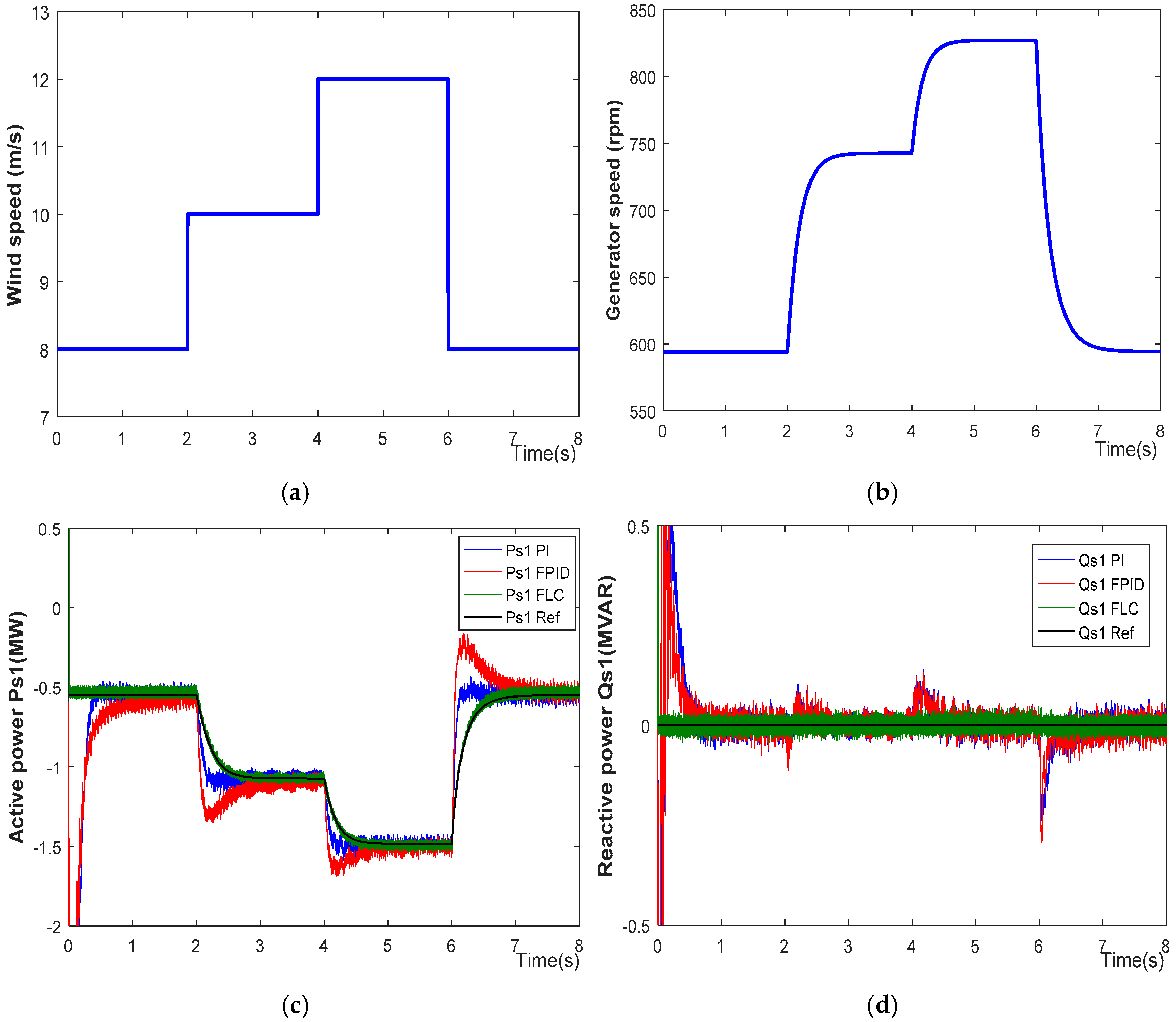
  • The reliability and applicability of the CDFIG controlled by an FLC were demonstrated under various conditions, including active power variations, smooth and step wind speed changes, and even the worst case of random wind speed variation.
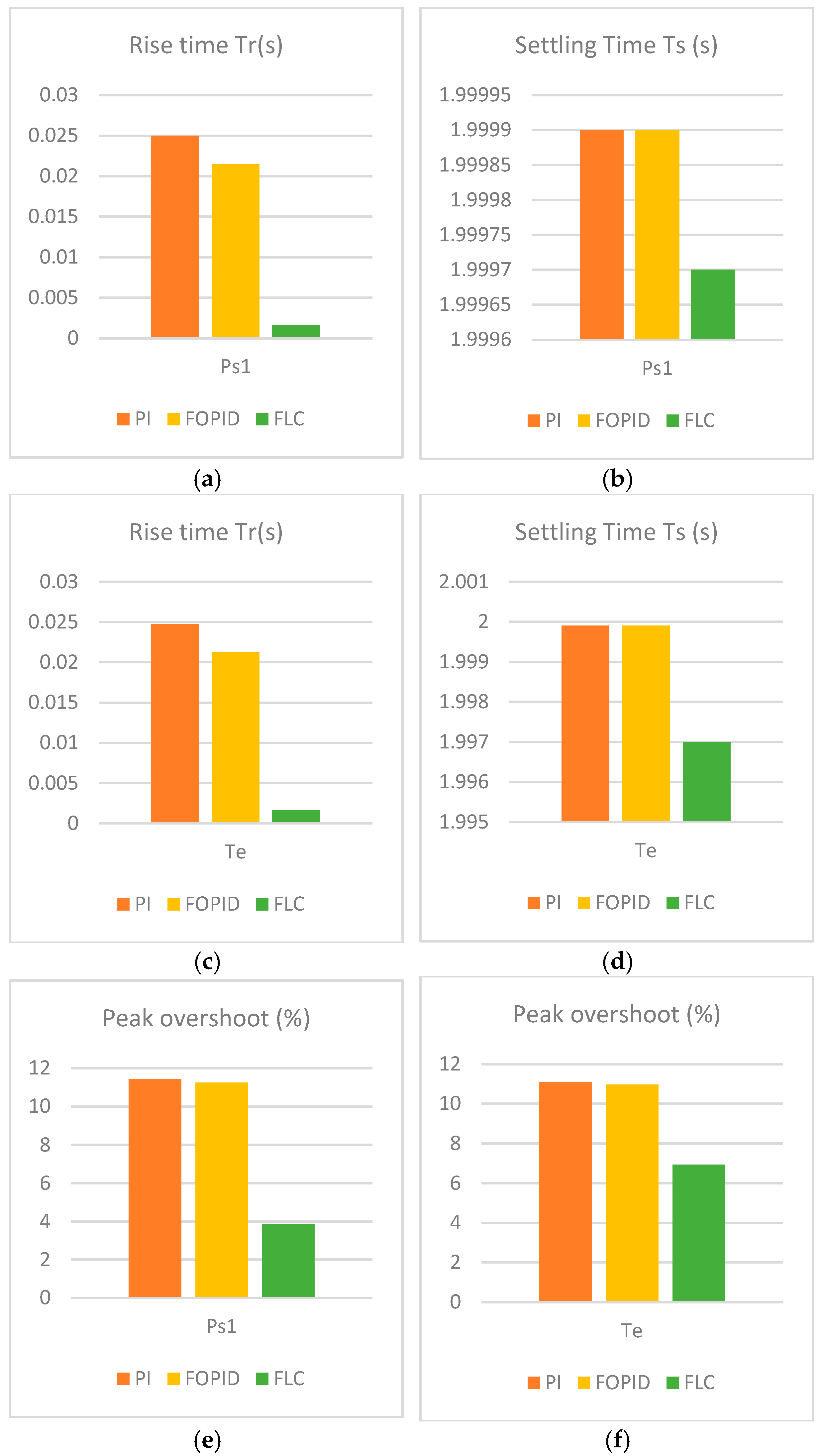
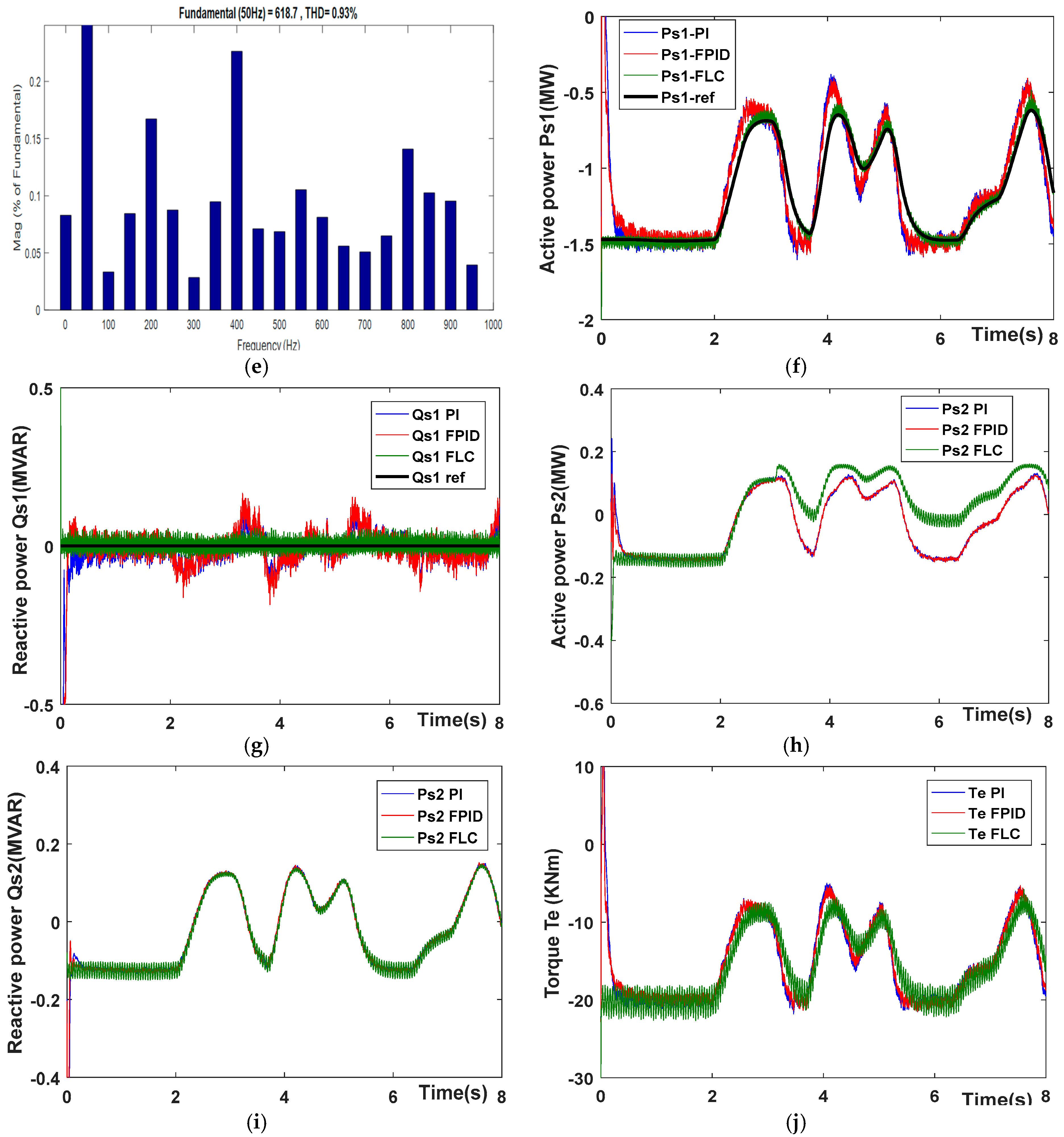
  • To demonstrate the effectiveness of the proposed FLC well, its performance was compared to well-established methods such as the use of PI and FOPID controllers.
The remainder of this paper is organized as follows.
Section 2 provides a summary of the mathematical modeling and a description of the energy conversion chain. Section 3 focuses on the design and implementation of the three controllers used in the WECS. Section 5 presents the simulation results and discusses the findings for all cases.

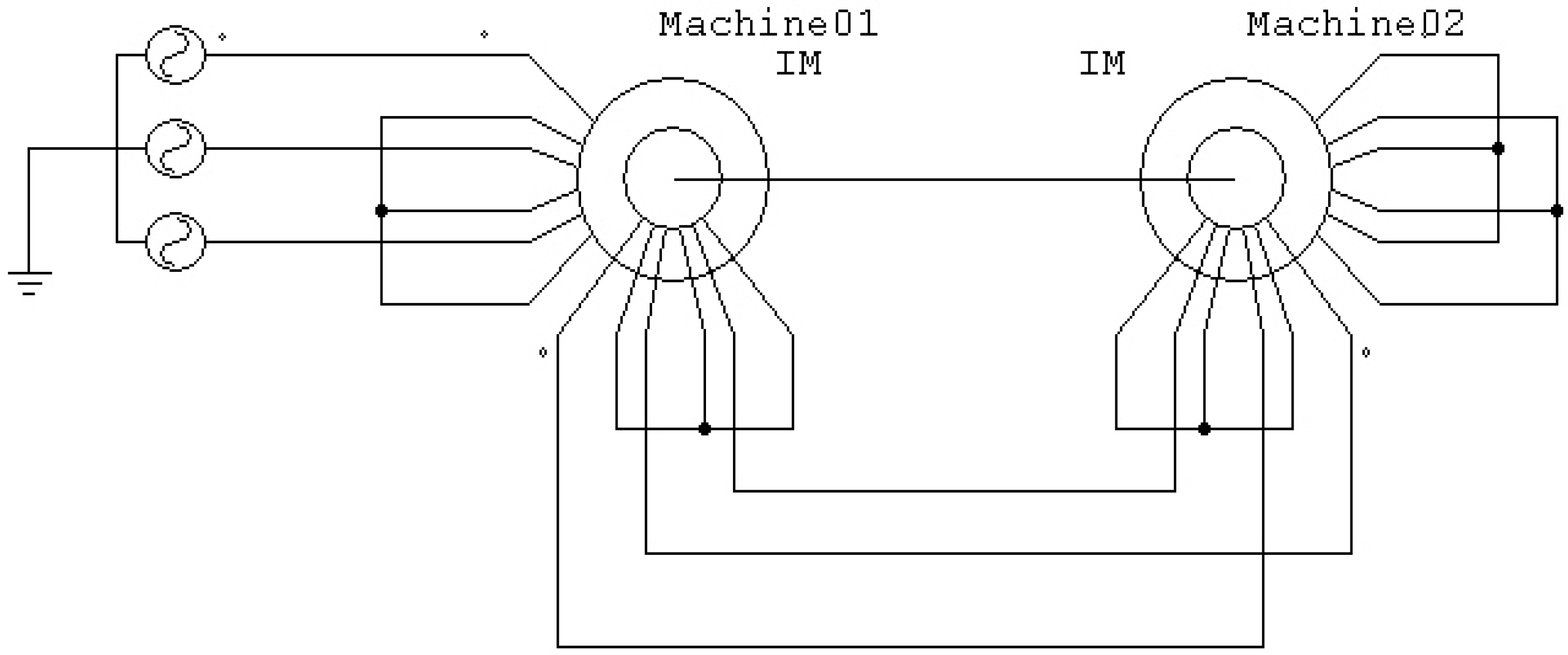
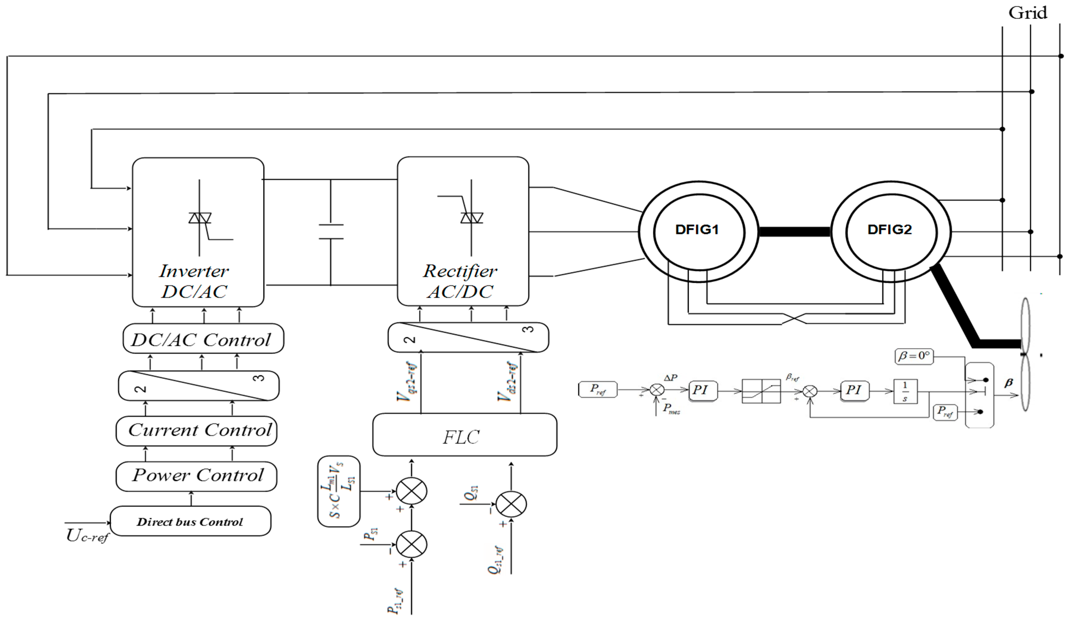
2. The Modeling and Description of the Energy Conversion Chain

CDFIGs represent a new area of research, but recently, a lot of studies have been published which concern several areas. Cascades can be found in wind power [49], small hydraulic power plants [50], and aviation [51].
The ring–brush system in DFIGs decreases their reliability; however, the electrical and mechanical coupling of two DFIGs via their rotors solves this issue by eliminating the need for sliding ring–brush contact. The entire system is called a CDFIG. In this case, succession coupling involves connecting the shafts and rotor windings in a reverse manner, resulting in the inversion of the rotor phases [40]. Figure 1 illustrates this coupling.
All equations are expressed in a frame of reference linked to the rotating field in the Park transform. The equations of the voltage and flux of the two DFIGs are as follows:
- DFIM 1:
v d s 1 = R s 1 i d s 1 + d φ d s 1 d t ω s 1 φ q s 1 v q s 1 = R s 1 i q s 1 + d φ q s 1 d t ω s 1 φ d s 1 v d r 1 = R r 1 i d r 1 + d φ d r 1 d t ( ω s 1 ω r 1 ) φ q r 1 v q r 1 = R r 1 i q r 1 + d φ q r 1 d t + ( ω s 1 ω r 1 ) φ d r 1
where v d s 1 , v d r 1 , and v q s 1 , v q r 1 represent the direct and quadrature voltage components of the stator and rotor, respectively, for the first DFIG. i d s 1 , i d r 1 , and i q s 1 , i q r 1 represent the direct and quadrature current components of the stator and rotor, respectively, for the first DFIG. φ d s 1 , φ d r 1 , and φ q s 1 , φ q r 1 denote the direct and quadrature voltage components of the stator and rotor, respectively, for the first DFIG R s 1 and R r 1 are the electrical resistance of the stator and rotor winding of one phase. ω s 1 is the speed of the synchronous reference frame of the first DFIG, and ω r 1 is the rotor electrical angular speed of the first DFIG.
φ d s 1 = L s 1 i d s 1 + L m 1 i d r 1 φ q s 1 = L s 1 i q s 1 + L m 1 i q r 1 φ d r 1 = L r 1 i d r 1 + L m 1 i d s 1 φ q r 1 = L r 1 i q r 1 + L m 1 i q s 1
L s 1 and L r 1 represent the total cyclic inductances of stator 1 and rotor 1, respectively.
L m 1 is the magnetizing inductance.
- DFIM 2:
v d r 2 = R r 2 i d r 2 + d φ d r 2 d t ( ω s 1 ω r 1 ) φ q r 2 v q r 2 = R r 2 i q r 2 + d φ q r 2 d t ( ω s 1 ω r 1 ) φ d r 2 v d s 2 = R s 2 i d s 2 + d φ d s 2 d t ( ω s 1 ω r 1 ω r 2 ) φ q s 2 v q s 2 = R s 2 i q s 2 + d φ q s 2 d t + ( ω s 1 ω r 1 ω r 2 ) φ q s 2
φ d s 2 = L s 2 i d s 2 + L m 2 i d r 2 φ q s 2 = L s 2 i q s 1 + L m 2 i q r 2 φ d r 2 = L r 2 i d r 2 + L m 2 i d s 2 φ q r 2 = L r 2 i q r 2 + L m 2 i q s 2
The two machines are identical, sharing the same equations and notations. We denote the first machine as 1 and the second machine as 2.
Modeling the electrical coupling of the two rotors depends on the type of coupling; the voltage and current equations are as follows:
v d r 1 = v d r 2 = v d r v q r 1 = v q r 2 = v q r
i d r 1 = i d r 2 = i d r i q r 1 = i q r 2 = i q r
The multivariable system can be represented by state-space equations. Multiple choices are possible for the state vector. Among these, we will take the vector of the stator and rotor currents.
I = i d s 1 i q s 1 i d r i d q r i d s 2 i q s 2 T
In order to obtain differential equations, we will need to replace the flux in the voltage equations. These differential equations are expressed as follows:
U = Z I + L d I d t
With
Z = R s 1 - ω s 1 L s 1 0 - ω s 1 L m 1 0 0 ω s 1 L s 1 R s 1 ω s 1 L m 1 0 0 0 0 - ω g 1 L m 1 R r - ω g 1 L r 0 λ ω g 1 L m 2 ω g 1 L m 1 0 ω g 1 L r R r - λ ω g 1 L m 2 0 0 0 0 λ ω s 2 L m 2 R s 2 - L s 2 ω s 2 0 0 - λ ω s 2 L m 2 0 L s 2 ω s 2 R s 2
L = L s 1 0 L m 1 0 0 0 0 L s 1 0 L m 1 0 0 L m 1 0 L r 0 - λ L m 2 0 0 L m 1 0 L r 0 - λ L m 2 0 0 - λ L m 2 0   L s 2 0 0 0 0 - λ L m 2 0 L s 2

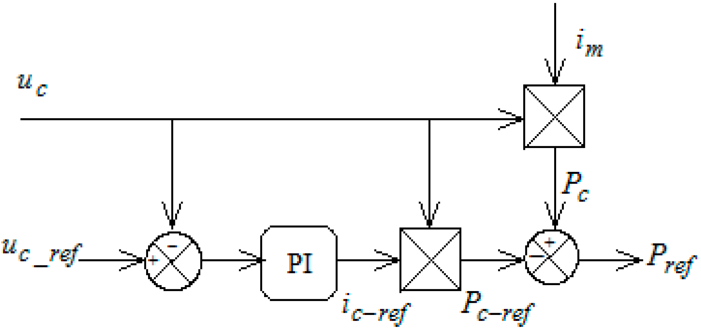
2.1. Control Powers of Stator-1

By aligning the d-axis of the (dq) reference frame with the flux of the first stator φs1, the steady-state model of the CDFIG is simplified as follows:
v d s 2 = R s 2 i d s 2 S . ω s ( L s 2 C . L m 2 ) . i q s 2 v q s 2 = R s 2 i q s 2 S . ω s ( L s 2 C . L m 2 ) . i d s 2 + C . S L m 1 . V s L s 1
where vds2 and vqs2 represent the two-phase voltage components of the second stator, which must be controlled to achieve the desired ids2 and iqs2 current levels in the machine. The influence of coupling terms between the d and q axes in S . ω s L s 2 C . L m 2 is minimal and can be effectively compensated for through proper regulator synthesis.
On the other hand, the term C . S . ( L m 1 V s )/ L s 1 represents an electromotive force that is dependent on the rotational speed. This term’s influence is significant as it introduces a tracking error. Therefore, the control strategy must account for this error to ensure accurate system performance.
The powers of stator-1 can be controlled through the currents of stator-2 by the following system of equations:
P s 1 = C . V s L m 1 . L s 1 i q s 2 Q q s 1 = V s 2 ω s L s 1 1 + C . L m 1 2 L s 1 L m 2 C . V s L m 1 L s 1 . i d s 2
With S = s 1 . s 2 = ω s 1 ω r 1 ω r 2 ω s 1 = ω s 1 Ω ( p 1 + p 2 ) ω s 1 , and C = L m 2 / ( L r 1 + L r 2 L m 1 2 L s 1 ) .
Finally, we can control the active power Ps1 and reactive power Qs1 exchanged between the network and stator-1 through the currents of stator-2 ids2 and iqs2.

2.2. The Modeling of the Connection to the Electrical Network

The main objective is to maintain zero reactive power to ensure a unity power factor on the network side in order to optimize efficiency. Then, the active power sent to the network is adjusted to its reference value, and the DC bus voltage is kept constant. The frequency converter (rectifier–inverter) and the CDFIG coupled to the network are shown in Figure 2.
The DC/AC converter, on the network side, is modeled as follows:
v i n 1 v i n 2 v i n 3 = u c 3 2 1 1 1 2 1 1 1 2 f 1 f 2 f 3
The current flowing through the grid side inverter is defined as follows:
i g = f 1 i i n 1 + f 2 i i n 2 + f 3 i i n 3
The AC/DC converter can be modeled as follows:
v a s 2 v b s 2 v c s 2 = u c 3 2 1 1 1 2 1 1 1 2 f 1 f 2 f 3
The current flowing through the machine-side rectifier is defined as follows:
i g = f 1 i a s 2 + f 2 i b s 2 + f 3 i c s 2
( f 1 ,   f 2 ,   f 3 ) and ( f 1 ,   f 1 ,   f 1 ) are logical connection functions of inverter and rectifier switches, respectively.
The current, which flows in the capacitor, comes from the rectifier on the machine side and inverter from the network side:
i c = i m i g
The temporal evolution of the DC link voltage is obtained from the integration of capacitive current:
d u c d t = 1 c ( i m i g )
The diagram in Figure 2 shows that the connection to the electrical network is made via an input filter. By applying the Park transformation, we can write the following:
v n d = R r i n d + L r d i n d d t e q + E d v n q = R r i n q + L r d i n q d t + e d + E q
With
e d = L r ω s i n d e d = L r ω s i n q
The reference power of the DC link is as follows:
P d c r e f = u c i c r e f
The DC link voltage regulation block is presented in Figure 3.
The active and reactive powers exchanged with the network are defined as follows:
P = E d i d r e f + E q i q r e f Q = E q i d r e f + E d i q r e f
We can derive the reference currents from Equation (21):
i d r e f = P r e f E d + Q r e f E q E d 2 + E q 2 i q r e f = P r e f E q Q r e f E d E d 2 + E q 2
The Id current is used to regulate the DC link voltage. It is controlled using a regulator (PI). Iq is used to regulate the reactive power transmitted. The regulation scheme for network currents is shown in Figure 4.

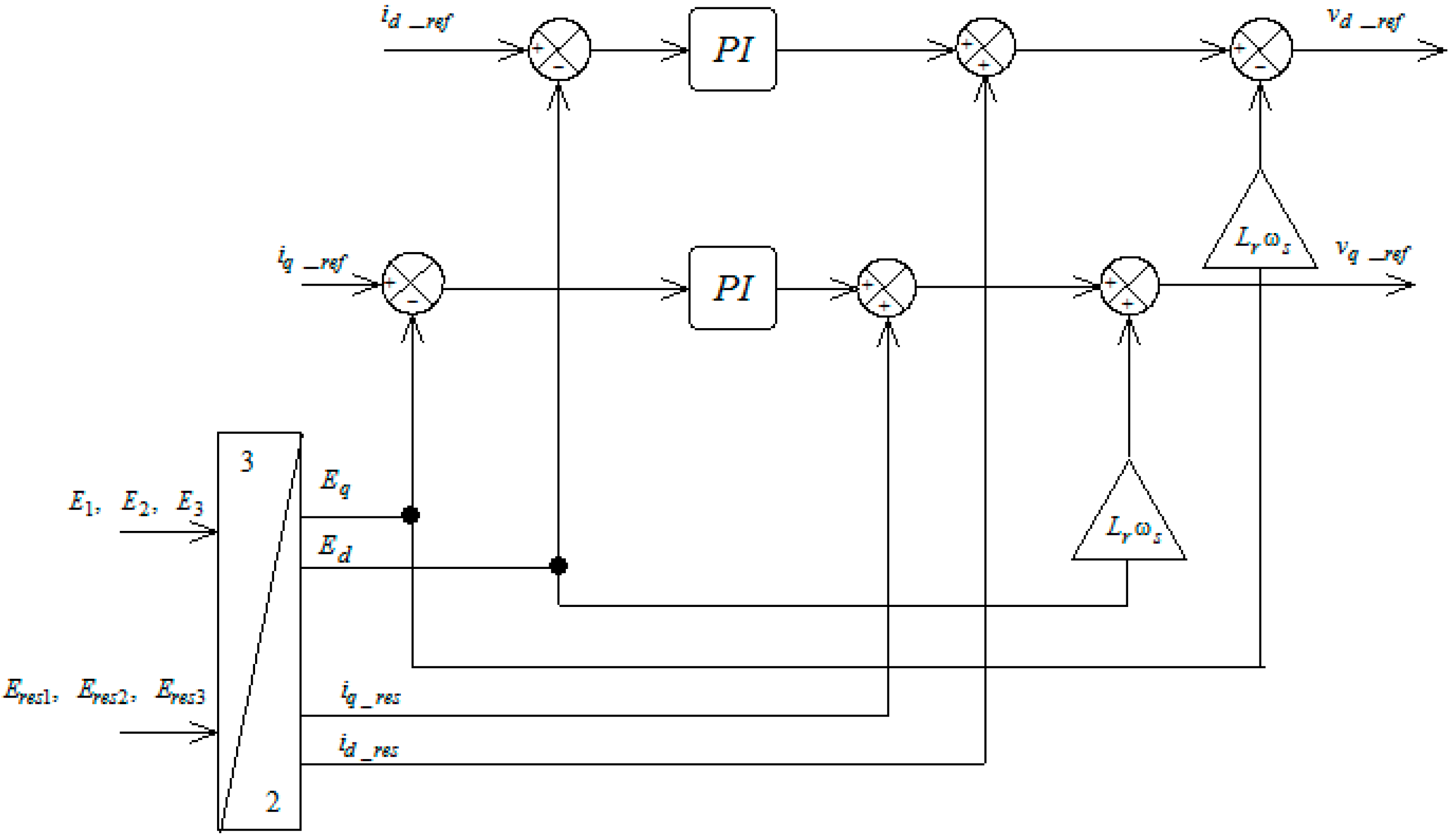
3. The Design of the Used Controllers

3.1. PI Controller

The regulation of wind power systems with proportional–integral controllers has been the subject of a great number of publications that have been published in the academic literature [52,53,54,55,56,57]. PI controllers, used in CDFIG control, are simple and quick to implement while offering acceptable performance (dynamic performance, robustness, and disturbance rejection). Figure 5 shows the closed-loop system, corrected by a classical PI controller, with its transfer function presented as follows:
G P I S = k p + k i S
The system’s response time is approximately 10 milliseconds, which is sufficiently rapid for usage on WTs, where wind fluctuations are gradual, and mechanical time constants are significant. Lowering the value may not enhance overall performance, but it could potentially result in disturbances during transient situations, resulting in undesired effects and instabilities. We used the pole compensation method here for its speed; it is obvious that it is not the only valid method for the synthesis of the PI controller. The results of our calculations are as follows: kp = 0.000118, and ki = 0.00184.

3.2. Fractional-Order PID Controller

A fractional PID (Proportional–Integral–Derivative) controller is an extension of the classic PID controller, has the form PIλDμ, and uses derivatives and integrals of a fractional order rather than integers. This approach makes it possible to control dynamic systems with greater flexibility and precision. The coefficients µ and λ are positive real numbers such that 0 < λ < 1, 0 < µ < 1. There are different kinds of FOPID controllers, including the PID (with λ = 1 and µ = 1), PI (with λ = 1 and µ = 0), PD (with λ = 0 and µ = 1), and P controllers (with λ = 0 and µ = 0) [58]. Figure 6 presents a graphical depiction of FPID controllers. The transfer function of the FOPID controller is expressed as follows:
G F O P I D s = k p + k i S λ + k d S μ
Recent research has shown that this controller’s performance, particularly its response speed and robustness, can be enhanced by changing to the fractional-order version [59,60,61,62]. The following is a list of the parameters that were used for the FOPID controller in order to find optimal solutions: kp = 0.000118, ki = 0.00184, kd = 0.0000000001, λ = 0.9, and μ = 0.5.

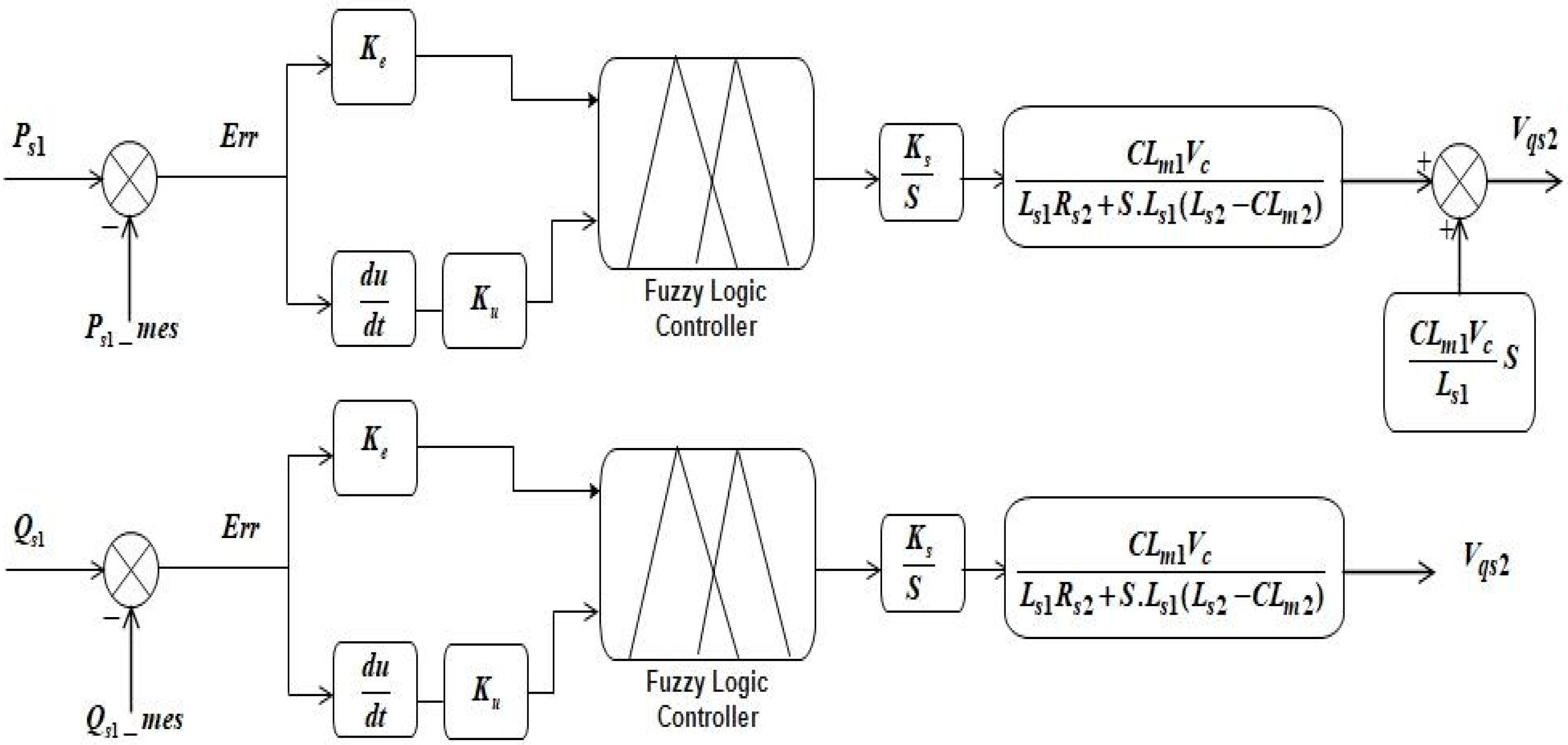
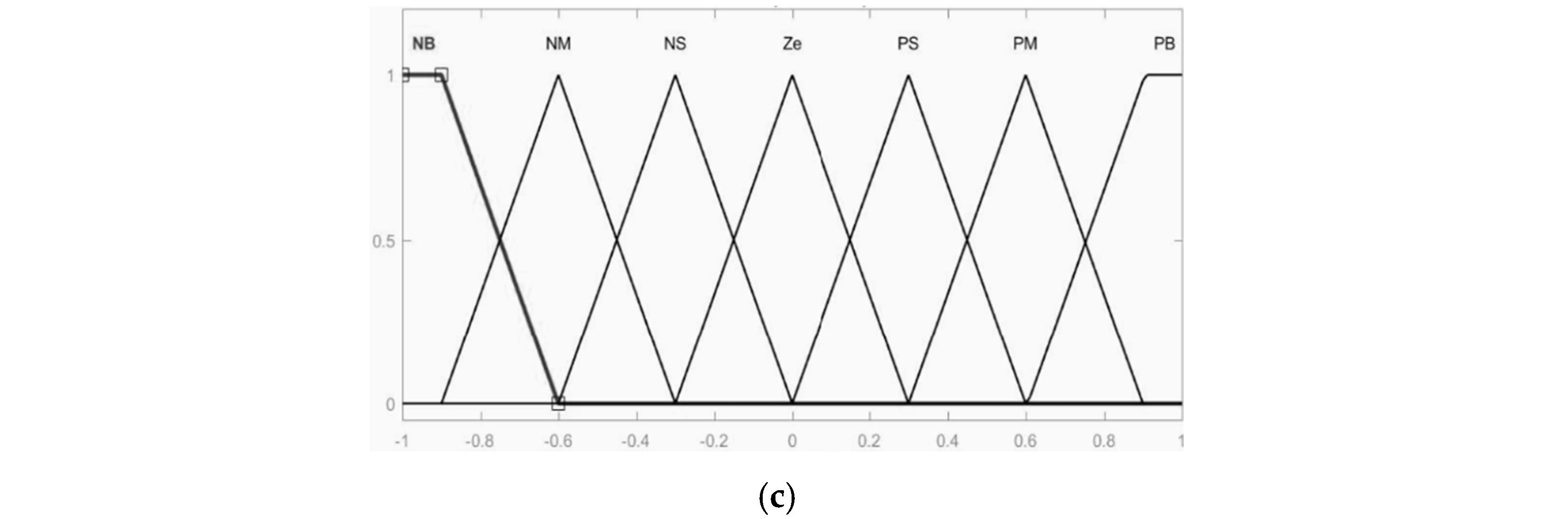
3.3. Fuzzy Logic Controller

The FLC is a type of controller that is based on fuzzy logic, which is a type of logic that works with approximate notions rather than precise values. A fuzzy logic controller (FLC) uses reasoning processes that are comparable to those that humans use. This is in contrast to standard control systems, which rely on precise mathematical models. Fuzzy logic is a form of multivalued logic in which the true value of a variable can be a real number between zero and one, which is considered “fuzzy”. In Boolean logic, the truth value of a variable cannot be 0 or 1 (Figure 7) and is generally called a “net” value.
There are many works in the literature that have used fuzzy controllers for system regulation [63,64,65,66,67,68]. The fuzzification of inputs, the application of a rule base, inferring to integrate the rule results, and defuzzification are the phases that a fuzzy controller requires to create an accurate output. Following these processes enables the processing of imprecise data and the making of suitable decisions in complex settings. Fuzzy logic controllers are illustrated graphically in Figure 8.
The controller block consists of a Mamdani-based inference system, which uses the center of gravity method for defuzzification. The choice of defuzzification method is dependent on the number of input/output parameters, and a specific set of rules was constructed for this purpose.
The Mamdani-based Fuzzy Inference System (FIS) is characterized by its intuitive nature and easily interpretable rules compared to Sugeno’s FIS. Despite having less flexibility in system design, Mamdani’s FIS is better suited for human input. In contrast, Sugeno’s rules require more mathematical formulations. Given the novelty of applying FLCs in Wind Energy Conversion Systems (WECSs) based on Cascaded Doubly Fed Induction Generators (CDFIGs), human expertise is essential, making the Mamdani approach particularly suitable for complex industrial applications, such as in our case.
In this scenario, the Mamdani Fuzzy Inference System (FIS) was chosen over the Sugeno FIS because of its superior flexibility, accuracy, and ability to produce improved results. The plant control u is determined based on the two state variables, error (e) and the rate of change of error (de). The control laws of the FLC are specified by the rule matrix presented in Table 1, and their Membership functions are presented in Figure 9.

4. Outcomes and Discussion

4.1. Test 1. Effect of Active Power Variation

The purpose of this section is to examine the manner in which the regulator adjusts to alterations in the operating conditions, such as disturbances from the outside world. In order to compare the controllers’ replies, we will use active power reference steps. The outcomes of the current test are illustrated in Figure 10.
We can conclude from Figure 10a,b that all of the regulators follow the reference to active power. The outcomes demonstrate that the proposed FLC approach outperforms that of the PI and FPID controllers in terms of robustness and tracking accuracy.
The interval in the range of [4,5,6] s will be the focus of our analysis. Table 2 provides a summary of the various controllers’ rising times, settling times, and overshoots of active power stators and torque. The FLC’s response time is the shortest among the other controllers. It is estimated at 0.0016 s for active power and torque. The settling time is almost identical, with a small reduction observed for the FLC. For both active power and torque, the estimate is 1.9997. The FLC’s peak overshoot is relatively low when compared to that of the FOPID and PI controllers. The peak overshoot values for active power and torque are 3.8639 and 6.9401, respectively. Figure 11 represents a comparative examination of the proposed technique in relation to other strategies. The use of the FLC method, as suggested, effectively decreased the rise time, settling times, and peak overshoots. The data shown in Table 2 and Figure 11 provide evidence of the usefulness of the suggested FLC in enhancing the features of the energy system discussed in this paper, in comparison to the alternative controller.

4.2. Test 2. The Effect of the Inertia of the WT

The inertia of a WT is highly influenced by its size and rated power, both of which are consistently growing over time. During this test, we will combine the WT with the generator shaft. The active power used as a reference for the generator will now be the mechanical power generated by the WT. The inertia of the WT breaks sudden changes in wind speed. Figure 12a illustrates the wind profile that is applied to the WT. We apply wind steps to see the effect of the inertia of the WT on the dynamics of the system. Figure 12b shows the generator’s speed.
The generator’s speed follows the same profile as that of the wind speed but with a certain delay due to the WT’s inertia, which slows down the system’s response.
As shown in Figure 12c, the active power of the first stator is represented. It is denoted by the symbol Ps1_ref, which signifies the mechanical power that is generated by the WT and will serve as the reference power for the generator. Taking into consideration the FLC strategy in comparison to the PI and FOPID strategies, we are able to draw the conclusion that the FLC method produces satisfactory outcomes, particularly with regard to the tracking of the reference and the rejection of disturbances. So as to prevent the exchange of reactive energy with the network, the reactive power of the first stator is maintained at zero, as seen in Figure 12c, and with this particular figure, we are able to reaffirm that the FLC is superior to all of the other controllers

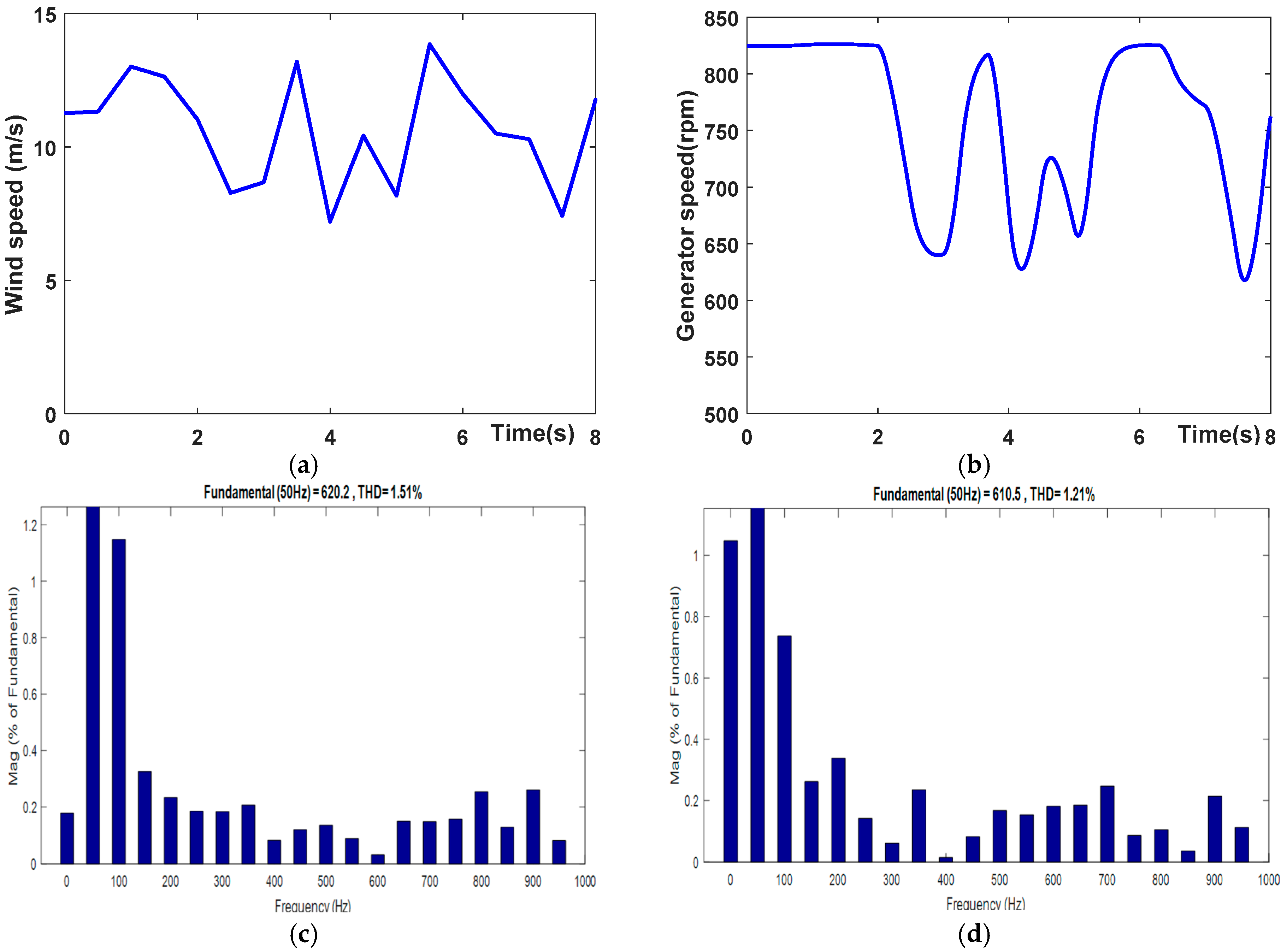
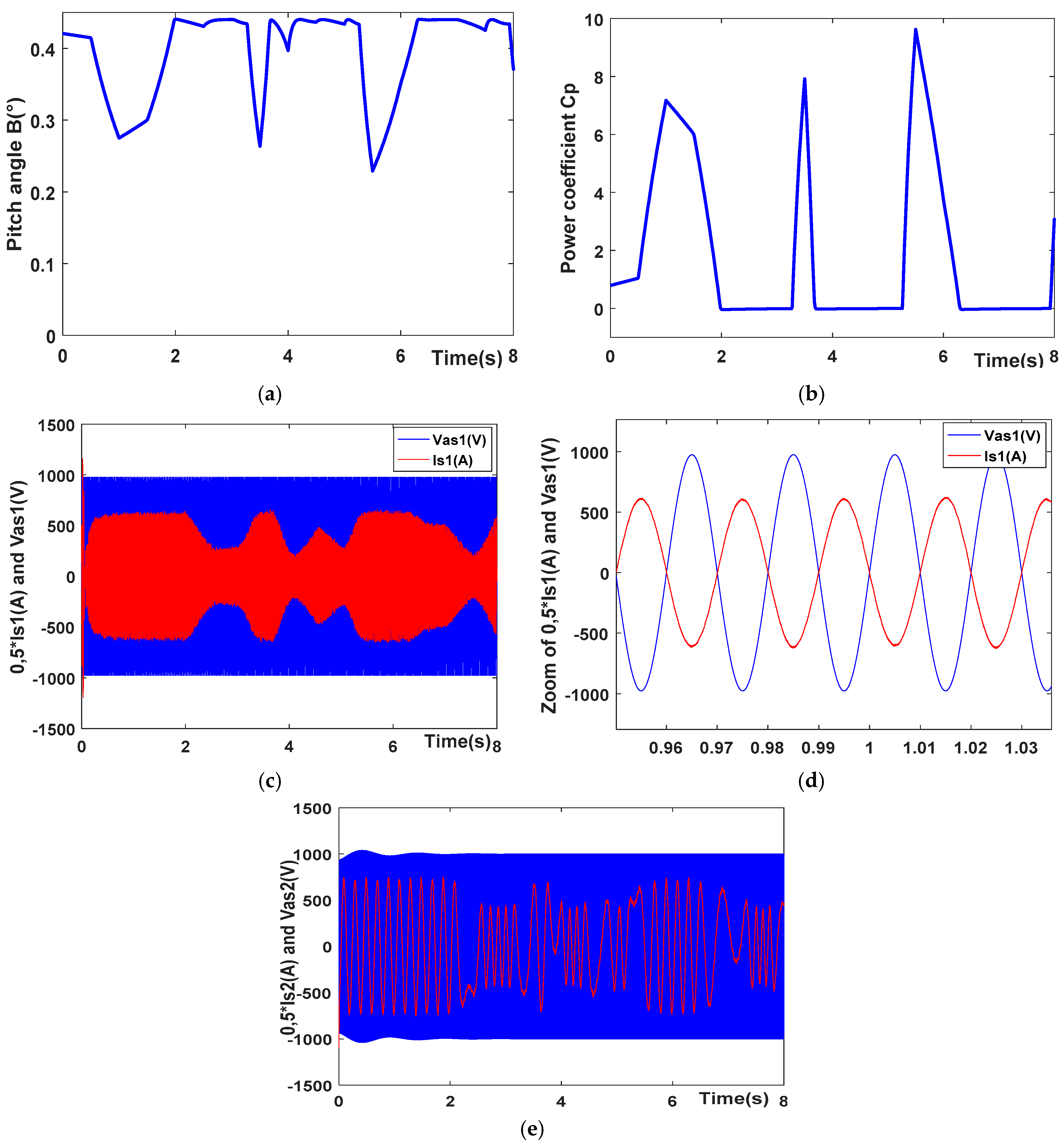
4.3. Test 3. Performance of CDFIG Under Random Wind Speed

During this third test, we perform an analysis of the complete system by using simulations of the entire chain of energy conversion. This includes the WT, the generator that is connected to the electrical network, and all of the energy control, management, and optimization systems. Direct power control is the approach that serves as a base for the control strategy. The active and reactive powers in the system are both under the control of this control independently. In order to regulate the amount of active power that is transmitted to the network by the first stator, we make adjustments to the supply voltages of the second stator. It is essential to exercise control on the aerodynamic power that is generated by the turbine. We make use of a switch in order to determine and thereafter select a suitable pitch angle. In situations where the aerodynamic power of the WT is less than the maximum power rating of the power converter, the angle is set to zero (β = 0°). The pitch angle is adjusted by the power converter once it reaches its maximum capacity. This is conducted in order to limit the amount of aerodynamic power. It is a proportional–integral (PI) controller that is responsible for determining this angle. The controller conducts this by comparing the nominal power with the measured power, which ultimately results in the WT running at a lower efficiency. The objective is to maximize the power that can be generated by the converter while staying within the limits that are considered acceptable. The energy conversion chain and its control are shown in Figure 13.
The wind speed that was applied to the energy conversion device is depicted in Figure 14a. Figure 14b illustrates the speed of the side shaft of the generator. Over-speed regimes are governed by the pitch control, which places a limit on this speed. An illustration of the total harmonic distortion (THD) of the first stator current can be found in Figure 14c–e.
Power quality is critical as it reflects the level of distortion within an electrical power system. Wind Energy Conversion Systems (WECSs) contribute to total harmonic distortion (THD) due to their intermittent nature, caused by wind fluctuations and nonlinear power electronic devices that generate harmonics and inter-harmonics. Elevated THD leads to voltage fluctuations, compromising system stability and increasing losses in components like transformers, generators, and cables through overheating. Moreover, high THD limits WECS grid integration and may result in disconnection to preserve grid stability if not properly managed.
We are able to confirm once more that the control strategy that makes use of fuzzy logic is the most effective by comparing it to the other three controllers, which are the PI controller (1.51%), FPID controller (1.21%), and FLC (0.93%), as presented in Table 3.
An illustration of the development of the active power as a function of wind variation can be found in Figure 14f. The power reference that is imposed by the turbine is followed by all of the control techniques (the use of PI, FPID, and FLC), with the exception of the FLC strategy, which is noticeably superior in terms of tracking and the rejection of disturbance. The reactive power of the first stator is displayed in Figure 14g. For the purpose of stopping the exchange of reactive power with the electrical network through the first stator, this power is maintained at zero. As the image demonstrates, the FLC method adheres to its reference in a satisfactory manner. The active power and reactive power of the second stator are represented in Figure 14h,i, respectively. These powers change based on the wind, with hyposynchronous positive speed positive powers and hypersynchronous negative speed powers. The torque is depicted in Figure 14j according to the three distinct methods. Just like the powers, torque has the same form.
The pitch control angle is represented in Figure 15a. An observation that we made is that the angle of inclination of the blades increases whenever the wind speed is greater than the nominal threshold. By increasing the pitch control, the power coefficient that is displayed in Figure 15b is reduced. This is conducted in order to limit the quantity of wind power that is captured by the WT. Figure 15c depicts the current and voltage characteristics of the first stator, and Figure 15d provides a zoomed-in view of the current and voltage of the stator. We note the fact that the current and the voltage are in phase opposition to one another. Additionally, the current and voltage of the second stator are depicted in Figure 15e. There is a correlation between the speed of the wind and the shape of the current.

5. Conclusions

The topic that is the focus of this article is the investigation of a control method that enables the management of energy that is generated by a WT and the optimization of its output. This study compares three different types of controllers, namely the PI controller, FPID controller, and FLC, with the main focus being on direct power control. The CDFIG is the name of the electromagnetic converter that was utilized in order to convert this energy.
The first test results demonstrate that when compared to other techniques such as the use of PI and FPID controllers, in terms of peak overshoot (%) for Ps and torque (Te), the findings reveal that the FLC-based technique (3.8639%, 6.9401%) outperforms that of both the FOPID (11.2458%, 10.9654%) and PI controllers (11.4219%, 11.0712%). This demonstrates the FLC’s superior ability to reduce overshoot, offering better control stability. Additionally, for the rise time (s) of Ps1 and Te, all controllers show similar performance. However, the FLC excels with rise times of 0.0016 s for both, significantly outperforming the FOPID (1.9999 s) and PI (0.0250 s, 0.0247 s) controllers. During the second test, which focused on examining the impact of different factors including the WT’s inertia, the results indicate that the FLC performs better than the other controllers at tracking the reference. After examining the THD curves of the first stator currents from the results of the third test, we can affirm that the intelligent fuzzy logic controller (FLC) surpasses the other controllers in terms of performance. Ultimately, we chose to utilize an intelligent approach, specifically the use of a fuzzy controller, for the generation and management of electrical energy generated by wind power.
Future work will focus on enhancing controller performance through optimization techniques such as Genetic Algorithms (GAs), Artificial Neural Networks (ANN), and Particle Swarm Optimization (PSO). Additionally, the proposed controllers will be validated through experimental testing. Efforts will also be made to improve power quality by reducing total harmonic distortion (THD) using advanced techniques.

Author Contributions

Conceptualization, A.M.; Methodology, H.M.; Validation, A.M. and H.M.; Formal analysis, K.B., B.B. and A.Y.; Investigation, H.S.; Resources, A.M. and H.M.; Writing—original draft, A.M., H.M. and K.B. All authors have read and agreed to the published version of the manuscript.

Funding

This article received no external funding.

Institutional Review Board Statement

Not applicable.

Informed Consent Statement

Not applicable.

Data Availability Statement

The original contributions presented in the study are included in this article; further inquiries can be directed to the corresponding author.

Acknowledgments

The authors thank Research Center in Industrial Technologies—CRTI, P.O. Box 64, 16014 Algiers, Algeria for supporting this work.

Conflicts of Interest

The authors declare no conflicts of interest.

References

  1. Wang, Q.; Luo, K.; Wu, C.; Tan, J.; He, R.; Ye, S.; Fan, J. Inter-farm cluster interaction of the operational and planned offshore wind power base. J. Clean. Prod. 2023, 396, 136529. [Google Scholar] [CrossRef]
  2. Ye, S.; Wang, Q.; Mu, Y.; Luo, K.; Fan, J. Loads and fatigue characteristics assessment of wind farm based on dynamic wake meandering model. Renew. Energy 2024, 236, 121419. [Google Scholar] [CrossRef]
  3. Zhang, X.; Wang, Q.; Ye, S.; Luo, K.; Fan, J. Efficient layout optimization of offshore wind farm based on load surrogate model and genetic algorithm. Energy 2024, 309, 133106. [Google Scholar] [CrossRef]
  4. Behara, R.K.; Saha, A.K. Analysis of Wind Characteristics for Grid-Tied Wind Turbine Generator Using Incremental Generative Adversarial Network Model. IEEE Access 2024, 12, 38315–38334. [Google Scholar] [CrossRef]
  5. Kumar, R.; Mishra, S.K.; Mohanta, D.K. An integrated development environment based situational awareness for operational reliability evaluation in wind energy systems incorporating uncertainties. Electr. Power Syst. Res. 2024, 233, 110467. [Google Scholar] [CrossRef]
  6. Akhtar, I.; Altamimi, A.; Khan, Z.A.; Alojaiman, B.; Alghassab, M.; Kirmani, S. Reliability Analysis and Economic Prospect of Wind Energy Sources Incorporated Microgrid System for Smart Buildings Environment. IEEE Access 2023, 11, 62013–62027. [Google Scholar] [CrossRef]
  7. Lohr, C.; Peterssen, F.; Schlemminger, M.; Bensmann, A.; Niepelt, R.; Brendel, R.; Hanke-Rauschenbach, R. Multi-criteria energy system analysis of onshore wind power distribution in climate-neutral Germany. Energy Rep. 2024, 12, 1905–1920. [Google Scholar] [CrossRef]
  8. Neshat, M.; Sergiienko, N.Y.; Nezhad, M.M.; da Silva, L.S.; Amini, E.; Marsooli, R.; Garcia, D.A.; Mirjalili, S. Enhancing the performance of hybrid wave-wind energy systems through a fast and adaptive chaotic multi-objective swarm optimisation method. Appl. Energy 2024, 362, 122955. [Google Scholar] [CrossRef]
  9. Rasool, S.; Muttaqi, K.M.; Sutanto, D. A Novel Configuration of a Hybrid Offshore Wind-Wave Energy Conversion System and Its Controls for a Remote Area Power Supply. IEEE Trans. Ind. Appl. 2022, 58, 7805–7817. [Google Scholar] [CrossRef]
  10. Majout, B.; Bossoufi, B.; Karim, M.; Skruch, P.; Mobayen, S.; El Mourabit, Y.; Laggoun, Z.E.Z. Artificial neural network-based direct power control to enhance the performance of a PMSG-wind energy conversion system under real wind speed and parameter uncertainties: An experimental validation. Energy Rep. 2024, 11, 4356–4378. [Google Scholar] [CrossRef]
  11. Maafa, A.; Abdelghani, Y.; Mellah, H.; Smail, H.; Sahraoui, H. Optimization of the Powers Exchanged between a Cascaded Doubly Fed Induction Generator and the Grid with a Matrix Converter. Eurasia Proc. Sci. Technol. Eng. Math. 2023, 26, 700–709. [Google Scholar] [CrossRef]
  12. Milles, A.; Merabet, E.; Benbouhenni, H.; Debdouche, N.; Colak, I. Robust control technique for wind turbine system with interval type-2 fuzzy strategy on a dual star induction generator. Energy Rep. 2024, 11, 2715–2736. [Google Scholar] [CrossRef]
  13. Hossain, M.A.; Chakrabortty, R.K.; Elsawah, S.; Gray, E.; Ryan, M.J. Predicting Wind Power Generation Using Hybrid Deep Learning with Optimization. IEEE Trans. Appl. Supercond. 2021, 31, 06013055. [Google Scholar] [CrossRef]
  14. Kushwaha, A.; Gopal, M.; Singh, B. Q-Learning based Maximum Power Extraction for Wind Energy Conversion System with Variable Wind Speed. IEEE Trans. Energy Convers. 2020, 35, 1160–1170. [Google Scholar] [CrossRef]
  15. Li, Y.; Yin, P.-K.; Chen, F.-B. Prediction of wind load power spectrum on high-rise buildings by various machine-learning algorithms. Structures 2024, 67, 107015. [Google Scholar] [CrossRef]
  16. Maafa, A.; Mellah, H.; Ghedamsi, K.; Aouzellag, D. Improvement of Sliding Mode Control Strategy Founded on Cascaded Doubly Fed Induction Generator Powered by a Matrix Converter. Eng. Technol. Appl. Sci. Res. 2022, 12, 9217–9223. [Google Scholar] [CrossRef]
  17. Li, N.; He, F.; Ma, W.; Wang, R.; Zhang, X. Wind Power Prediction of Kernel Extreme Learning Machine Based on Differential Evolution Algorithm and Cross Validation Algorithm. IEEE Access 2020, 8, 68874–68882. [Google Scholar] [CrossRef]
  18. Dineshkumar, C.; Jeong, J.H.; Joo, Y.H. Observer-based fuzzy control for fractional order PMSG wind turbine systems with adaptive quantized-mechanism. Commun. Nonlinear Sci. Numer. Simul. 2024, 136, 108087. [Google Scholar] [CrossRef]
  19. Benbouhenni, H.; Bizon, N.; Mosaad, M.I.; Colak, I.; Djilali, A.B.; Gasmi, H. Enhancement of the power quality of DFIG-based dual-rotor wind turbine systems using fractional order fuzzy controller. Expert Syst. Appl. 2024, 238, 121695. [Google Scholar] [CrossRef]
  20. Wadawa, B.; Errami, Y.; Obbadi, A.; Sahnoun, S. Robustification of the H∞ controller combined with fuzzy logic and PI&PID-Fd for hybrid control of Wind Energy Conversion System Connected to the Power Grid Based on DFIG. Energy Rep. 2021, 7, 7539–7571. [Google Scholar]
  21. Arifin, M.S.; Uddin, M.N.; Wang, W. Neuro-Fuzzy Adaptive Direct Torque and Flux Control of a Grid-Connected DFIG-WECS with Improved Dynamic Performance. IEEE Trans. Ind. Appl. 2023, 59, 7692–7700. [Google Scholar] [CrossRef]
  22. Chishti, F.; Murshid, S.; Singh, B. Weak Grid Intertie WEGS with Hybrid Generalized Integrator for Power Quality Improvement. IEEE Trans. Ind. Electron. 2020, 67, 1113–1123. [Google Scholar] [CrossRef]
  23. Tamaarat, A. Active and Reactive Power Control for DFIG Using PI, Fuzzy Logic and Self-Tuning PI Fuzzy Controllers. Adv. Model. Anal. C 2019, 74, 95–102. [Google Scholar] [CrossRef]
  24. Mokhtari, M.; Zouggar, S.; M’sirdi, N.K.; Elhafyani, M.L. Sliding Mode & Single Input Fuzzy Logic Controllers for Voltage Regulation of an Asynchronous Wind Turbine Using STATCOM. IFAC-PapersOnLine 2020, 53, 12803–12808. [Google Scholar]
  25. Zamzoum, O.; Derouich, A.; Motahhir, S.; El Mourabit, Y.; El Ghzizal, A. Performance analysis of a robust adaptive fuzzy logic controller for wind turbine power limitation. J. Clean. Prod. 2020, 265, 121659. [Google Scholar] [CrossRef]
  26. Gholamrezaie, V.; Dozein, M.G.; Monsef, H.; Wu, B. An Optimal Frequency Control Method Through a Dynamic Load Frequency Control (LFC) Model Incorporating Wind Farm. IEEE Syst. J. 2018, 12, 392–401. [Google Scholar] [CrossRef]
  27. Takayama, S.; Matsuhashi, R. Development of model for load frequency control in power system with large-scale integration of renewable energy. In Proceedings of the 2016 IEEE Power and Energy Conference at Illinois (PECI), Urbana, IL, USA, 19–20 February 2016; pp. 1–8. [Google Scholar]
  28. Ashfaq, T.; Mumtaz, S.; Ahmad, S.; Ullah, B.; Albogamy, F.R. Automatic Generation Control in Renewables-Integrated Multi-Area Power Systems: A Comparative Control Analysis. Sustainability 2024, 16, 5735. [Google Scholar] [CrossRef]
  29. Mehta, S.; Basak, P. Cascaded dual fuzzy logic controller for stable microgrid operation mitigating effects of natural uncertainty in solar and wind energy sources. e-Prime-Adv. Electr. Eng. Electron. Energy 2023, 5, 100215. [Google Scholar] [CrossRef]
  30. Salem, A.A.; Aldin, N.A.N.; Azmy, A.M.; Abdellatif, W.S.E. Implementation and Validation of an Adaptive Fuzzy Logic Controller for MPPT of PMSG-Based Wind Turbines. IEEE Access 2021, 9, 165690–165707. [Google Scholar] [CrossRef]
  31. Puchalapalli, S.; Singh, B. A Single Input Variable FLC for DFIG-Based WPGS in Standalone Mode. IEEE Trans. Sustain. Energy 2020, 11, 595–607. [Google Scholar] [CrossRef]
  32. El Mezdi, K.; El Magri, A.; Watil, A.; El Myasse, I.; Bahatti, L. Integrated Control and Energy Flow Management for Hybrid Grid-Connected Photovoltaic/Wind Systems with Battery Storage Using Fuzzy Logic Controllers. IFAC-PapersOnLine 2024, 58, 442–447. [Google Scholar] [CrossRef]
  33. Huerta, H.; Loukianov, A. Energy based sliding mode control of Brushless Double-fed Induction Generator. Int. J. Electr. Power Energy Syst. 2021, 130, 107002. [Google Scholar] [CrossRef]
  34. Huerta, H. Brushless Double-Fed Induction Generator Control: Passivity with High Order Sliding Modes Control. In Proceedings of the 2023 9th International Conference on Control, Decision and Information Technologies (CoDIT), Rome, Italy, 3–6 July 2023; pp. 602–607. [Google Scholar]
  35. Liu, Y.; Hussien, M.G.; Xu, W.; Shao, S.; Rashad, E.M. Recent Advances of Control Technologies for Brushless Doubly-Fed Generators. IEEE Access 2021, 9, 123324–123347. [Google Scholar] [CrossRef]
  36. Dauksha, G.; Górski, D.; Iwański, G. State-feedback control of a grid-tied cascaded brushless doubly-fed induction machine. Electr. Power Syst. Res. 2024, 228, 110043. [Google Scholar] [CrossRef]
  37. Cheng, M.; Cao, Z.; Yan, X. Dual-Negative-Objective Coordinated Control of Brushless Doubly Fed Induction Generator under Unbalanced Grid Voltage. CES Trans. Electr. Mach. Syst. 2024, 8, 347–355. [Google Scholar] [CrossRef]
  38. Elnaghi, B.E.; Abelwhab, M.N.; Mohammed, R.H.; Abdel-Kader, F.E.S.; Ismaiel, A.M.; Dessouki, M.E. The Validation and Implementation of the Second-Order Adaptive Fuzzy Logic Controller of a Double-Fed Induction Generator in an Oscillating Water Column. Electronics 2024, 13, 291. [Google Scholar] [CrossRef]
  39. Maafa, A.; Mellah, H.; Sahraoui, H.; Yahiou, A. Performance improvement of a DPC-FPID strategy with matrix converter using CDFIG in wind power system. Wind. Eng. 2024. [Google Scholar] [CrossRef]
  40. Maafa, A.; Aouzellag, D.; Ghedamsi, K.; Abdessemed, R. Cascaded doubly fed induction generator with variable pitch control system. Rev. Roum. Sci. Tech.-Électrotechn. Énerg 2016, 61, 361–366. [Google Scholar]
  41. Hopfensperger, B.; Atkinson, D.J.; Lakin, R.A. Combined magnetising flux oriented control of the cascaded doubly-fed induction machine. IEE Proc.-Electr. Power Appl. 2001, 148, 354. [Google Scholar] [CrossRef]
  42. Han, P.; Cheng, M.; Chen, Z. Single-Electrical-Port Control of Cascaded Doubly-Fed Induction Machine for EV/HEV Applications. IEEE Trans. Power Electron. 2017, 32, 7233–7243. [Google Scholar] [CrossRef]
  43. El Achkar, M.; Mbayed, R.; Salloum, G.; Le Ballois, S.; Monmasson, E. Generic study of the power capability of a cascaded doubly fed induction machine. Int. J. Electr. Power Energy Syst. 2017, 86, 61–70. [Google Scholar] [CrossRef]
  44. Patin, N.; Monmasson, E.; Louis, J.-P. Modeling and control of a cascaded doubly-fed induction generator based on dynamical equivalent circuits. Math. Comput. Simul. 2010, 81, 225–238. [Google Scholar] [CrossRef]
  45. Sadeghi, R.; Madani, S.M.; Agha-kashkooli, M.; Ataei, M. Reduced-order model of cascaded doubly fed induction generator for aircraft starter/generator. IET Electr. Power Appl. 2018, 12, 757–766. [Google Scholar] [CrossRef]
  46. Hopfensperger, B.; Atkinson, D.J.; Lakin, R.A. Stator flux oriented control of a cascaded doubly-fed induction machine. IEE Proc.-Electr. Power Appl. 1999, 146, 597. [Google Scholar] [CrossRef]
  47. Patin, N.; Monmasson, E.; Louis, J.-P. Modeling and Control of a Cascaded Doubly Fed Induction Generator Dedicated to Isolated Grids. IEEE Trans. Ind. Electron. 2009, 56, 4207–4219. [Google Scholar] [CrossRef]
  48. Mehrjardi, R.T.; Ershad, N.F.; Rahrovi, B.; Ehsani, M. Detailed Model of the Grid-Connected Cascaded Doubly Fed Induction Machine. IEEE Trans. Ind. Appl. 2022, 58, 3414–3423. [Google Scholar] [CrossRef]
  49. Protsenko, K.; Xu, D. Modeling and Control of Brushless Doubly-Fed Induction Generators in Wind Energy Applications. IEEE Trans. Power Electron. 2008, 23, 1191–1197. [Google Scholar] [CrossRef]
  50. Adamowicz, M.; Strzelecki, R. Cascaded doubly fed induction generator for mini and micro power plants connected to grid. In Proceedings of the 2008 13th International Power Electronics and Motion Control Conference, Poznan, Poland, 1–3 September 2008; pp. 1729–1733. [Google Scholar]
  51. Abdolhadi, H.Z.; Markadeh, G.A.; Boroujeni, S.T. Sliding Mode and Terminal Sliding Mode Control of Cascaded Doubly Fed Induction Generator. Iran. J. Electr. Electron. Eng. 2021, 17, 3. [Google Scholar]
  52. Hawari, Q.; Kim, T.; Ward, C.; Fleming, J. A robust gain scheduling method for a PI collective pitch controller of multi-MW onshore wind turbines. Renew. Energy 2022, 192, 443–455. [Google Scholar] [CrossRef]
  53. Turksoy, O.; Ayasun, S.; Hames, Y.; Sönmez, Ş. Computation of Robust PI-Based Pitch Controller Parameters for Large Wind Turbines. Can. J. Electr. Comput. Eng. 2020, 43, 57–63. [Google Scholar] [CrossRef]
  54. Du, Z.; Yufan, F.; Yang, X.; Li, J. Design of PI Controller for a Class of Discrete Cascade Control Systems. IEEE Trans. Autom. Sci. Eng. 2023, 20, 2607–2615. [Google Scholar] [CrossRef]
  55. Kakkar, S.; Maity, T.; Ahuja, R.K.; Walde, P.; Saket, R.K.; Khan, B.; Padmanaban, S. Design and Control of Grid-Connected PWM Rectifiers by Optimizing Fractional Order PI Controller Using Water Cycle Algorithm. IEEE Access 2021, 9, 125941–125954. [Google Scholar] [CrossRef]
  56. Sreenu, C.; Mallesham, G.; Shekar, T.C.; Salkuti, S.R. Pairing voltage-source converters with PI tuning controller based on PSO for grid-connected wind-solar cogeneration. Frankl. Open 2024, 8, 100138. [Google Scholar] [CrossRef]
  57. Naqvi, S.S.; Jamil, H.; Iqbal, N.; Khan, S.; Lee, D.I.; Park, Y.C.; Kim, D.H. Multi-objective optimization of PI controller for BLDC motor speed control and energy saving in Electric Vehicles: A constrained swarm-based approach. Energy Rep. 2024, 12, 402–417. [Google Scholar] [CrossRef]
  58. Idir, A.; Canale, L.; Bensafia, Y.; Khettab, K. Design and Robust Performance Analysis of Low-Order Approximation of Fractional PID Controller Based on an IABC Algorithm for an Automatic Voltage Regulator System. Energies 2022, 15, 8973. [Google Scholar] [CrossRef]
  59. Shi, J.Z. A Fractional Order General Type-2 Fuzzy PID Controller Design Algorithm. IEEE Access 2020, 8, 52151–52172. [Google Scholar] [CrossRef]
  60. Gao, P.; Zhang, G.; Ouyang, H.; Mei, L. An Adaptive Super Twisting Nonlinear Fractional Order PID Sliding Mode Control of Permanent Magnet Synchronous Motor Speed Regulation System Based on Extended State Observer. IEEE Access 2020, 8, 53498–53510. [Google Scholar] [CrossRef]
  61. Frikh, M.L.; Soltani, F.; Bensiali, N.; Boutasseta, N.; Fergani, N. Fractional order PID controller design for wind turbine systems using analytical and computational tuning approaches. Comput. Electr. Eng. 2021, 95, 107410. [Google Scholar] [CrossRef]
  62. Gupta, D.K.; Dei, G.; Soni, A.K.; Jha, A.V.; Appasani, B.; Bizon, N.; Srinivasulu, A.; Nsengiyumva, P. Fractional order PID controller for load frequency control in a deregulated hybrid power system using Aquila Optimization. Results Eng. 2024, 23, 102442. [Google Scholar] [CrossRef]
  63. Benbouhenni, H.; Colak, I.; Bizon, N.; Mosaad, M.I.; Tella, T.G. Power regulation of variable speed multi rotor wind systems using fuzzy cascaded control. Sci. Rep. 2024, 14, 16415. [Google Scholar] [CrossRef]
  64. Chaoui, H.; Khayamy, M.; Aljarboua, A.A. Adaptive Interval Type-2 Fuzzy Logic Control for PMSM Drives with a Modified Reference Frame. IEEE Trans. Ind. Electron. 2017, 64, 3786–3797. [Google Scholar] [CrossRef]
  65. Krishnama Raju, S.; Pillai, G.N. Design and Implementation of Type-2 Fuzzy Logic Controller for DFIG-Based Wind Energy Systems in Distribution Networks. IEEE Trans. Sustain. Energy 2016, 7, 345–353. [Google Scholar] [CrossRef]
  66. Alika, R.; Mellouli, E.M.; Tissir, E.H. A modified sliding mode controller based on fuzzy logic to control the longitudinal dynamics of the autonomous vehicle. Results Eng. 2024, 22, 102120. [Google Scholar] [CrossRef]
  67. Triviño, A.; López, A.; Yuste, A.J.; Cuevas, J.C. Decentralized EV charging and discharging scheduling algorithm based on Type-II fuzzy-logic controllers. J. Energy Storage 2024, 93, 112054. [Google Scholar] [CrossRef]
  68. Choon, N.H.; Cheah, Y.N.; Goh, O.S.; Choo, Y.H.; Basiron, H.; Kumar, Y.J. A Review on Automated Menu Planning Approaches. J. Comput. Sci. 2016, 12, 582–596. [Google Scholar]
Figure 1. The connection of the CDFIG to the electrical network.
Sustainability 16 09333 g001
Figure 2. The connection of the CDFIG to the electrical network via power converters.
Sustainability 16 09333 g002
Figure 3. DC link regulation scheme.
Sustainability 16 09333 g003
Figure 4. Network-side current regulation scheme.
Sustainability 16 09333 g004
Figure 5. Closed-loop system.
Sustainability 16 09333 g005
Figure 6. FOPID controller applied to WECS.
Sustainability 16 09333 g006
Figure 7. Range of logical values: (a) Boolean logic, (b) fuzzy logic [63].
Sustainability 16 09333 g007
Figure 8. Design of fuzzy logic controller.
Sustainability 16 09333 g008
Figure 9. Membership functions: (a) error (e), (b) change of error (de), (c) output (u).
Sustainability 16 09333 g009aSustainability 16 09333 g009b
Figure 10. Various controllers’ responses to power steps: (a) active power, (b) generator torque.
Sustainability 16 09333 g010
Figure 11. A comparative study between FLC, PI, and FOPID characteristics for the torque and active power: (a) Ps1 rise time Tr (s); (b) Ps1 settling time Ts (s); (c) Te rise time Tr (s); (d) Te settling time Ts (s); (e) Ps1 peak overshoot (%); (f) Te peak overshoot (%).
Sustainability 16 09333 g011
Figure 12. Characteristics of CDFIG with integration of inertia of wind turbine: (a) wind speed (m/s); (b) generator speed (rpm); (c) Ps1 (MW); (d) Qs1 (MVAR).
Sustainability 16 09333 g012
Figure 13. The energy conversion chain and its control.
Sustainability 16 09333 g013
Figure 14. Characteristics of CDFIG with random wind speed: (a) wind speed (m/s); (b) generator speed (rpm); (c) THD of first stator; (d) THD of first stator; (e) THD of first stator; (f) Ps1 (MW); (g) Qs1 (MVAR); (h) Ps2 (MW); (i) Qs2 (MVAR); (j) torque Te (KN.m).
Sustainability 16 09333 g014aSustainability 16 09333 g014b
Figure 15. Characteristics of CDFIG with energy production system.
Sustainability 16 09333 g015
Table 1. Rule matrix for FLC.
eNBNMNSZEPSPMPB
du
NBNBNBNBNBNMNSZE
NMNBNBNBNMNSZEPS
NSNBNBNMNSZEPSPM
ZENBNMNSZE PSPMPB
PSNMNSZEPSPMPBPB
PMNSZEPSPMPBPBPB
PBZEPSPMPBPBPBPB
Table 2. Comparative analysis of proposed controllers.
Ps1Te (kN.m)
PIRise time Tr (s)0.02500.0247
Settling time Ts (s)1.99991.9999
Peak overshoot (%)11.421911.0712
FOPIDRise time Tr (s)0.02150.0213
Settling time Ts (s)1.99991.9999
Peak overshoot (%)11.245810.9654
FLCRise time Tr (s)0.00160.0016
Settling time Ts (s)1.99971.9997
Peak overshoot (%)3.86396.9401
Table 3. THD of proposed controllers.
ControllerPIFPIDFLC
THD1.51%1.21%0.93%
Disclaimer/Publisher’s Note: The statements, opinions and data contained in all publications are solely those of the individual author(s) and contributor(s) and not of MDPI and/or the editor(s). MDPI and/or the editor(s) disclaim responsibility for any injury to people or property resulting from any ideas, methods, instructions or products referred to in the content.

