Article

Effect of Interlayer Composition on the Properties of Laser-Directed-Energy-Deposition-Based Additively Manufactured Copper-Stainless Steel Wall Structures

1
Homi Bhabha National Institute, Anushaktinagar, Mumbai 400094, India
2
Additive Manufacturing Technology Lab, Raja Ramanna Centre for Advanced Technology, Indore 452013, India
3
School of Computing, Engineering and Digital Technologies, Teesside University, Middlesbrough TS1 3BX, UK
*
Authors to whom correspondence should be addressed.
Sustainability 2024, 16(2), 519; https://doi.org/10.3390/su16020519
Submission received: 24 November 2023 / Revised: 21 December 2023 / Accepted: 5 January 2024 / Published: 7 January 2024

Abstract

:
Laser-directed energy deposition (LDED) is one of the advanced techniques used for the sustainable manufacturing of engineering components with minimal material wastage and higher performance. This paper reports an investigation on LDED-based additive manufacturing of compositionally graded Copper (Cu)-stainless steel (SS) wall structures for improved performance of tooling components. Three different approaches, such as Cu-SS direct joint, 20% graded Cu-SS, and 50% graded Cu-SS, are used to build the wall structures. Optical microscopy of LDED-built graded samples reveals defect-free deposition of Cu-SS direct joint and 50% graded Cu-SS wall structures at identified process parameters, whereas the 20%-graded wall yields micro-cracks in the lower Cu region. The elemental distribution shows gradual traditions in the weight percentages of Cu and Fe along the built wall. Furthermore, the ultimate tensile strengths of the direct Cu-SS joint wall structure and the 50%-graded Cu-SS wall structure are higher than the strength of LDED-deposited Cu, while the 20%-graded Cu-SS wall structure has lower ultimate tensile strength than the strength of LDED-deposited Cu. Lower ultimate strength and failure in the lower-Cu zone of 20% graded Cu-SS wall structure can be attributed to the presence of micro-cracks in the Cu20SS80 zone of 20%-graded Cu-SS wall structures. The study establishes LDED as a technique for building multi-material components promoting sustainability in terms of manufacturing and component performance.

1. Introduction

Laser additive manufacturing (LAM) is a significant subset of additive manufacturing (AM) technologies that plays a pivotal role in creating components with minimal material wastage, thereby contributing to sustainability efforts [1]. The sustainability aspect of LAM comes from the fabrication methodology, which uses the digital data of a part to selectively add the material as per the required geometry using layer-wise building methodology. The above methodology minimizes/eliminates the need for machining of the components, leading to minimal waste generation. LAM is generally categorized into two primary methods: laser powder bed fusion (LPBF) and laser-directed energy deposition (LDED). The key distinction between them lies in how they feed the raw material, which can be in the form of either powder or wire. In addition, LAM deploys a high-power laser beam as a heating source to melt the feedstock material. LPBF finds application in building highly complex parts using fine powders and lasers with beam diameters in micron scale. Out of the two LAM techniques, LDED is used for building multi-material components due to its uniqueness in a combination of material and shape design freedom [1,2]. In addition, conventional methods employed for achieving spatial variations in compositions or structures include power metallurgy, vapor deposition, centrifugal casting, and welding. These traditional techniques are associated with challenges such as slower production rates, lower bond strength, limited geometrical complexity, and restricted material versatility [1]. LDED accomplishes this multi-material capacity through two significant approaches. Firstly, it employs pre-mixed powder feeding—in which various powders, each representing a specific material—are simultaneously introduced into the melt-pool. This approach facilitates the creation of components with gradient properties, known as functionally graded materials (FGM), which exhibit varying material compositions at different locations within the component to meet specific performance requirements [3,4]. Secondly, by employing a multi-feeder system, LDED can produce multi-material components by utilizing multiple feeders, each delivering a different material. These feeders operate at predetermined rates, offering precise control over the material composition at various points within the component. This method can be particularly valuable in cases where materials need to be strategically positioned for optimal performance [5]. LDED using powders has wide applications due to its geometry control, precision, and easy process control. Numerous studies have been conducted to demonstrate the capability of LDED for building FGM or multi-material components [3,4,5,6,7,8,9].
The fabrication of multi-material components aids in joining materials with a significant difference in thermo-physical properties and materials that form intermetallics/brittle precipitates at the interface [10]. In addition, the multi-material components develop properties that are different from the individual materials aiding in tailored structures, properties, and performance [11]. Out of various combinations of multi-material, FGM or multi-material of copper (Cu)–stainless steel (SS) stands out as a significant and ongoing research area with diverse applications, including tooling, cryogenic systems, power generation, and heat transfer industries [12]. Cu-SS FGMs or multi-material structures are meticulously engineered to leverage the advantageous thermal conductivity of Cu in combination with the superior strength and corrosion resistance of SS within a single component. However, the production of Cu-SS FGMs or multi-material components presents substantial challenges owing to the pronounced disparities in thermo-physical properties—such as thermal expansion coefficient, melting point temperature, and thermal conductivity—between Cu and SS. Additionally, the limited solubility of Cu and Fe in each other even at higher temperatures increased the complexity of building Cu-SS structure using LDED. It may be noted that the solubility of Cu and Fe with each other is poor (maximum Cu solubility in Fe is about 10 wt. % even at higher temperatures (i.e., ~1550 K), whereas the solubility of Fe in Cu is less than 5 wt. % at 1550 K [13,14].These above-mentioned challenges often result in the formation of solidification cracks and porosity at the interface of LDED-built direct Cu-SS joints [6,15,16,17]. One of the techniques employed to address these issues stemming from abrupt interfaces is the creation of FGMs, which offer a more gradual transition in material properties.
The literature highlights the complexity of fabricating Cu-SS joints (FGM and direct joining) through AM and welding, with the outcome influenced by the Cu-SS composition and processing parameters [15,16,18]. The investigation carried out by Noecker II et al. involved tungsten arc welding of tool steel–Cu composites, and it was observed that as the concentration of Cu decreased, there was an increased vulnerability to the crack formation during the solidification process [17]. This susceptibility varied from low to high as the Cu weight percentages changed from 100% to 50% in the Cu-SS systems [17]. In a similar manner, Articek et al. underscored the significance of having sufficient terminal Cu available during the solidification process. They observed higher tensile strength in Cu–tool steel components deposited using LDED with various compositions, in contrast to pure samples. Their findings led to the conclusion that issues related to porosity and crack formation primarily result from suboptimal process parameters [15]. Zhang et al. incorporated a layer of a nickel-based superalloy between them as a solution to address these challenges, allowing for the successful production of multi-material Cu–tool steel injection molds using LDED [16]. In another study, Osipovich et al. showcased the potential of wire-feed based AM, particularly through a twin-feeder system, for creating transition joints in Cu-SS materials [19]. Furthermore, in one of our recent research endeavors, we built bulk Cu-SS FGM with varying grading percentages, employing specific composition-dependent parameters [12]. This investigation revealed that when employing multi-track and multi-layer depositions, which involve repeated thermal cycles, liquation cracking tends to occur in regions with lower Cu compositions [12]. One effective approach to mitigate liquation cracking is to minimize the number of thermal cycles by constructing wall structures. Additionally, Cu-SS wall structures offer the potential to replace traditionally manufactured stainless steel fins, thereby improving cooling efficiency and reducing fin dimensions. This enhancement in cooling performance and size reduction of fins contributes to the development of radiators, chillers, condensers, and more. Furthermore, in terms of sustainability, LDED is one of the techniques that can be used for building thin-walled components with minimal wastage and reduced distortion as compared to subtractive manufacturing techniques [20].
However, a review of the existing literature reveals a dearth of information concerning Cu-SS wall structures built through LDED. Consequently, this study seeks to address this gap by investigating the use of LDED to fabricate functionally graded Cu-SS wall structures with varying grading percentages. The research endeavors to investigate the influence of varying grading percentages on deposit quality, microstructure evolution, and mechanical behavior.

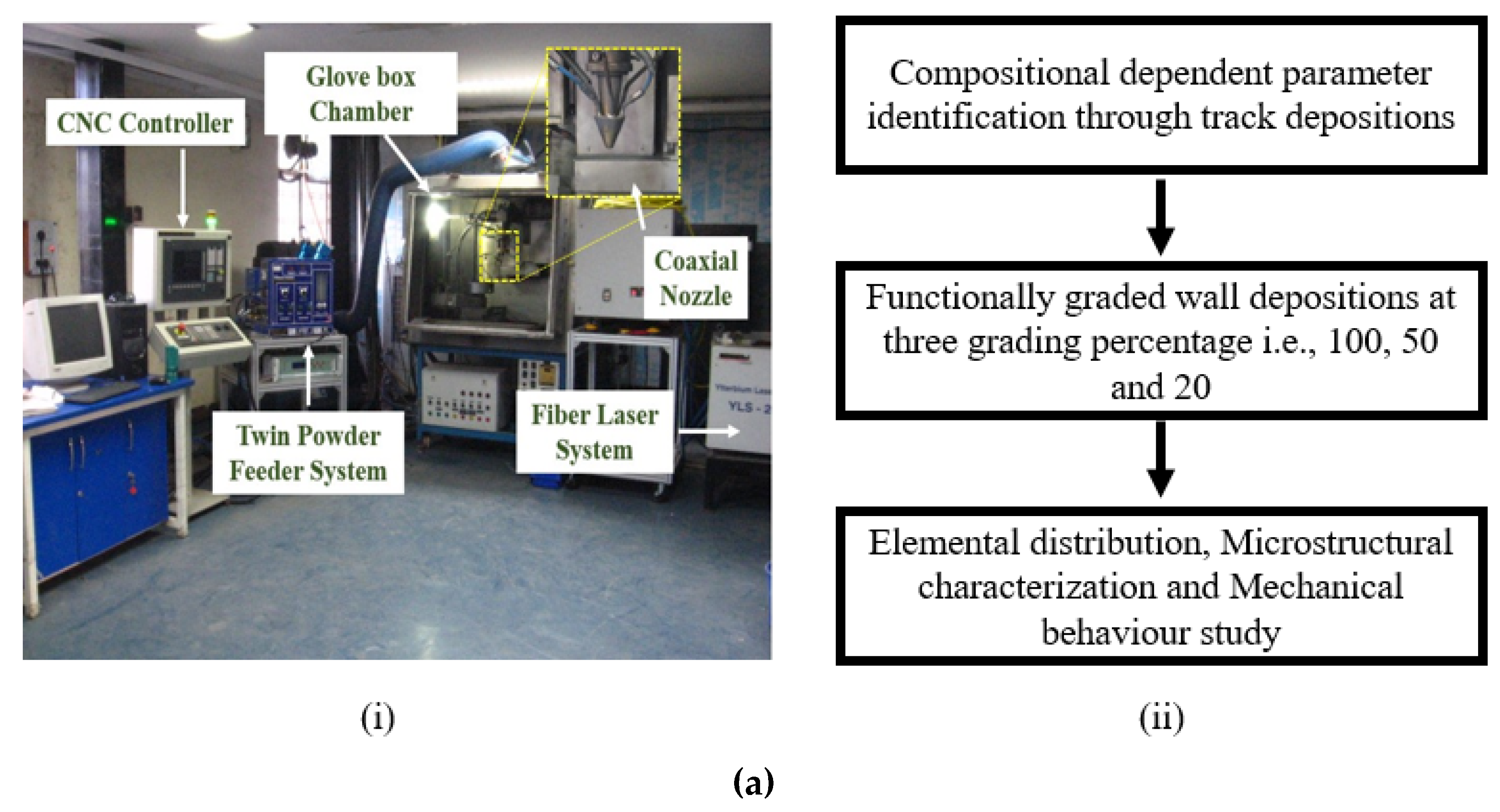
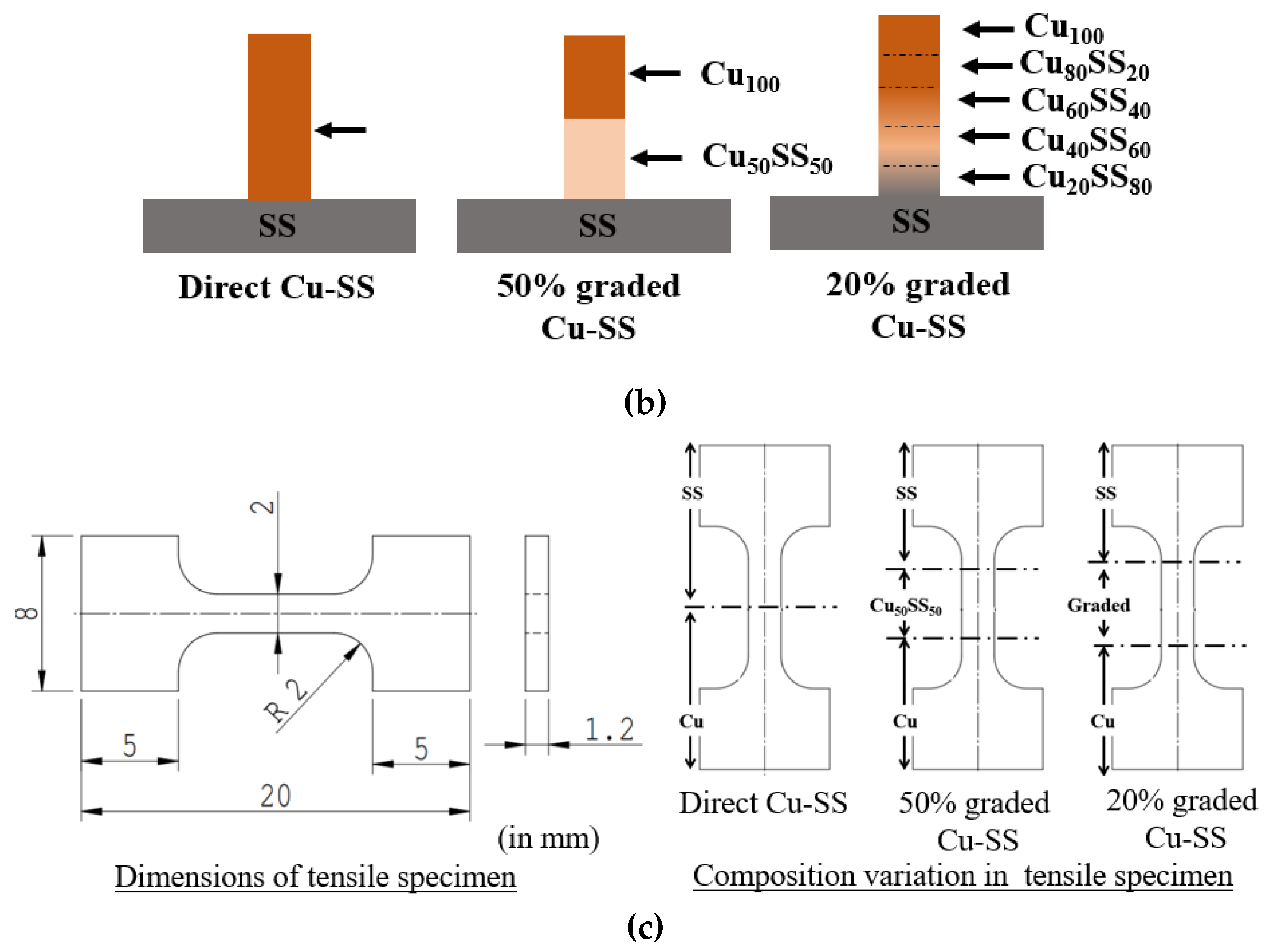
2. Materials and Methods

LDED of FG Cu-SS wall structures is conducted using an in-house-developed LDED system, as shown in Figure 1(a,i) [12], and the flow chart shown in Figure 1(a,ii) reveals the experimental procedure. For the experiments, commercially available SS 304L powder and Cu powder are employed. SS 304L steel grade is used in the present investigation, considering the better weldability of SS304L along with its application in heat transfer equipment such as heat sinks, tubes-pipes, injection moulds, heat exchangers, dissimilar joints, etc., in power generation, the tooling industry, the aerospace sector, the medical industry, etc. [3,12]. Before the deposition process begins, the Cu and SS powders are meticulously blended with various compositions, denoted as Cu X SS 100-X, with “X” taking on values of 20, 40, 50, 60, and 80. This blending is carried out thoroughly for a duration of 3 h at a rotational speed of 70 revolutions per minute utilizing a specialized powder-mixing machine.
Full factorial experiments are carried out by varying laser power (600–1800 W), scan speed (0.3–0.7 m/s) and powder feed rate (4–8 g/min) at three-level each for depositing tracks and wall structures of Cu-SS mix composition [12]. Furthermore, Cu-SS FGM wall structures are deposited as per Figure 1b at the identified process parameter (combination of laser power, scan speed, and powder feed rate) as mentioned in Table 1 and are used for depositing individual blended compositions of Cu-SS [12,21]. Subsequently, LDED-deposited wall structures are sectioned perpendicular to the scan-direction using wire EDM, mounted, and polished by following standard metallurgical guidelines. Chemical etching is conducted using a blended solution composed of 5 g of ferric chloride, 25 mL of hydrochloric acid, and 100 mL of ethanol. Optical microscopy, utilizing the LEICA DM 2700M model, is employed to conduct a qualitative examination of structural integrity and the detection of cracks. In parallel, scanning electron microscopy (SEM) equipped with energy-dispersive spectroscopy (EDS), featuring the Carl Zeiss Sigma model, is utilized for elemental mapping and fractographic analysis. Vickers micro-hardness measurement is carried out at a load of 100 gm for a dwell time of 10 s (make: Omnitech, model: MVH-S Auto). Single-cycle automated ball indentation (ABI) is performed to measure the energy storage capability of the material with respect to different Cu-SS compositions. ABI is performed using a spherical hardened tool steel ball indenter with a diameter of 1 mm (make: Biss). ABI test is carried out for a loading cycle of 50 N load and an unloading cycle up to 5 N load with a pre-load of 5 N. The area under the curve is estimated to measure the energy absorption capability of the material. To assess the strength of the Cu-SS joint, micro-tensile testing is conducted using a universal testing machine with a loading capacity of 5 kN (Manufacturer: SDAtlas, Model: H5kL) at a strain rate of 0.001 s−1. Micro-tensile samples are sub-size specimens prepared by following the standard mechanical tensile testing methodology available in the literature, as shown in Figure 1c [12]. The tensile specimen is designed in such a way that all the interfaces and graded regions lie within the gauge length.

3. Results and Discussion

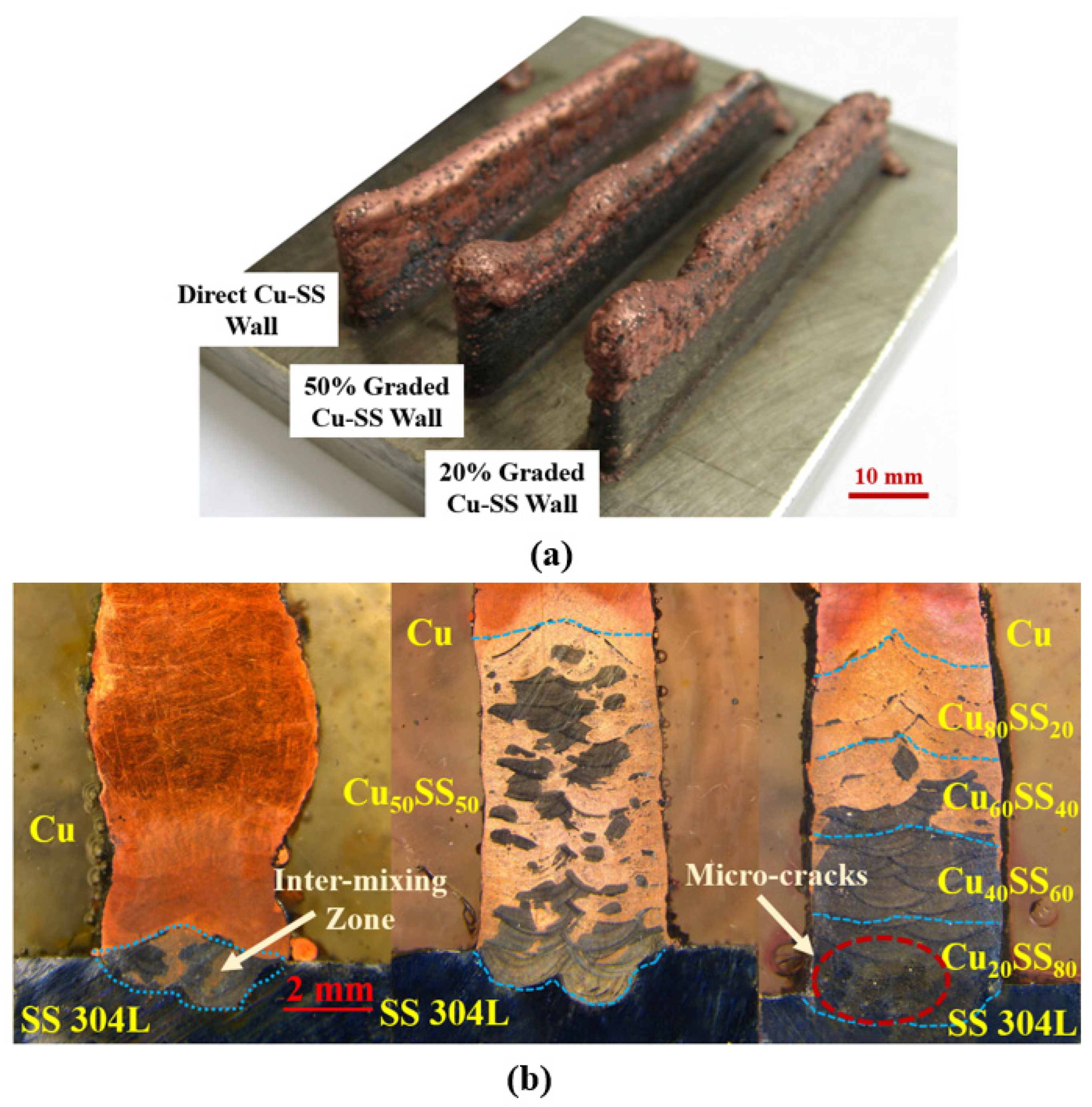
3.1. LDED of Graded Wall

LDED of FG Cu-SS wall structures is carried out at identified process parameters for each composition as per Table 1. The compositional dependent parameter is identified by laying tracks of each composition as per the process parameter combinations mentioned earlier. The compositional dependent parameter selection is based on the quality of the track (continuity and surface defects), cross-sectional defects (cracks and porosity), and aspect ratio (track width/track height). A detailed investigation is carried out to identify process parameters for each composition and process parameter yielding defect-free depositions (crack and porosity), and an aspect ratio greater than or equal to five is selected for further processing [12,21]. Figure 2a illustrates the photographic view of the LDED-deposited Cu-SS wall structures with a direct Cu-SS joint and the 50%- and 20%- graded Cu-SS walls. It is observed that LDED-built Cu-SS wall structures yield non-uniformity in the Cu deposited region. This can be attributed to the agglomeration behaviour of Cu arising due to its lower surface tension [21]. Figure 2b presents the cross-sectional view along the build direction of LDED deposited wall structures. As depicted in Figure 1b, the schematic illustrates the complete elemental transition from SS to Cu as it progresses along the build direction. Due to the limited solubility of the Cu-Fe system and the faster solidification inherent to LDED, it yields a distinctive morphology characterized by randomly distributed and phase-separated Cu- and Fe-rich zones, as depicted in Figure 2b.
It is observed that these graded walls yield defect-free depositions at the identified process parameters (refer to Figure 2). In addition, it is observed at a few locations that LDED-built 20%-graded Cu-SS wall structures yield micro-cracks in the lower Cu region (Cu20SS80 and Cu40SS60). Figure 3 represents a typical trapping behavior of Cu and micro-crack in the lower Cu region of the 20% graded wall. It is observed that the entrapment of Cu predominantly occurs within the inter-dendritic or grain boundary regions, manifesting as thin films or isolated Cu structures. The solidifying Fe particle displaces the liquid Cu towards these inter-dendritic areas or grain boundaries due to their lower solubility, leading to the sequestration of Cu within these regions. The formation of micro-cracks in the lower Cu region can be explained as provided below.
As solidification begins, the Fe particles start solidifying (due to higher melting point temperature) and pushing out the Cu liquid particles from the Fe matrix due to lower solubility of Cu-Fe into each other (≤10% even at higher temperature 1503 K). This leads to the trapping of liquid Cu particles or film in solidifying Fe grain (inter-dendritic region or grain boundary, refer to Figure 3a). Further, as the solidification process progresses, this liquid Cu film is subjected to tensile strain due to the solidification of Fe and Cu. Moreover, if this Cu film is unable to effectively absorb the generated tensile strain, it leads to the formation of micro-cracks in the Cu film (refer to Figure 3b). Another possibility of micro-crack formation is liquation cracks during multi-layer depositions due to trapping of the weak phase, i.e., Cu occurs in thin film or phase-separated morphologies during solidification. While depositing multiple layers above this Cu-trapped region, this Cu film suffers from a continuous heating and cooling cycle incurring thermal strain due to expansion and contraction. If this generated thermal strain in the trapped Cu film is above the ultimate tensile strength of Cu, then it may lead to crack or micro-crack generation in the trapped film.

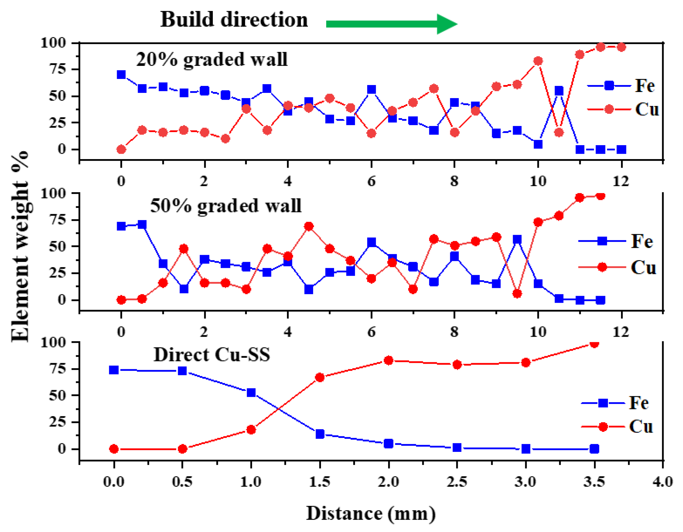
3.2. Elemental Distribution across the Graded Wall

Figure 4 showcases the transition in composition from Fe to Cu along the build direction, as quantified through EDS-point analysis. The LDED-fabricated direct Cu-SS bulk material exhibits a sharp change in compositions, specifically in terms of the weight percentages of both Fe and Cu, consistent with the intended design. In the case of walls graded built at 20% and 50% grading, a gradual shift in the measured weight percentages of both Fe and Cu, coupled with localized fluctuations within the graded zone, is observed (refer to Figure 4). The step-by-step variation in the composition aids in the gradual change in mechanical and thermo-physical properties of the FG wall structures. These fluctuations in compositions can be attributed to the presence of randomly distributed Cu-rich and Fe-rich zones, as initially depicted in Figure 2b.

3.3. Microstructural Transformation across the Graded Wall

Figure 5 illustrates the microstructural transformation with compositions in LDED-built FG wall structures. The predominant re-melting and heat transfer through the previously deposited layers leads to epitaxial grain growth occurring along the build direction giving rise to columnar grain growth within the Cu-zone of LDED-built structures [12], as demonstrated in Figure 5a. Moreover, it is evident that the Fe-rich zone exhibits fine columns with a dendritic morphology characterized by the entrapment of Cu within the inter-dendritic zone. This phenomenon can be attributed to the accelerated solidification process caused by the presence of liquid Cu within the melt pool leading to faster heat transfer. In addition, rejected Cu particles from the solidifying Fe-rich zone restrict the grain growth causing finer dendritic morphology (refer to Figure 5b). It is also observed that the re-melted zone has finer dendritic columnar morphology (refer to Figure 5b). The formation of these finer morphologies can be attributed to the availability of multiple heterogeneous nucleation sites during re-melting and rapid cooling during LDED. It is also observed at a few locations in the lower Cu region that dendritic morphology yields micro-porosity assisted with the presence of Cu (refer to Figure 5c). This micro-porosity arises from the shrinkage of trapped liquid Cu during the terminal stage of solidification [22]. As solidification progresses, trapped liquid particles start shrinking, and the unavailability of liquid Cu in the trapped inter-dendritic zone leads to the generation of voids or micro-porosity.

3.4. Mechanical Behavior of Graded Wall

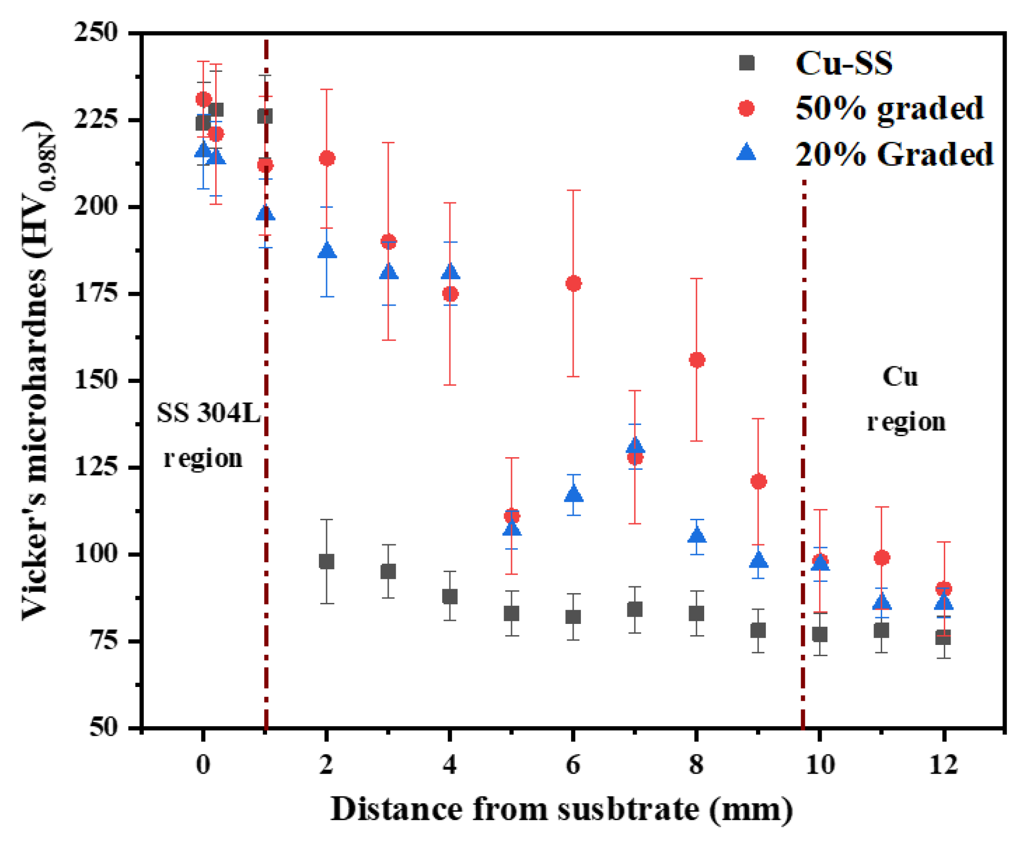
3.4.1. Variation in Micro-Hardness with Compositions

Figure 6 presents the variation in micro-hardness along the grading direction in graded walls. A gradual transition in micro-hardness variation is observed along the build direction with respect to compositions (refer to Figure 6). The variation in measured micro-hardness value is observed from 215 ± 6 HV0.98N to 88 ± 6 HV0.98N along the build direction from the SS zone to the Cu zone. However, the formation of local Fe and Cu-rich zones leads to large variations in micro-hardness values in 20% and 50% graded walls. The micro-hardness within the Cu zone built by LDED falls within the range of 78 HV0.98N to 92 HV0.98N. It is observed that the measured value of LDED built Cu is higher than the hardness value of conventional rolled Cu [12,23]. This higher hardness in the Cu zone can be attributed to the smaller microstructural features of LDED built Cu. Furthermore, it is worth noting that the Cu-rich zone within the blended or graded area exhibits micro-hardness values exceeding 99 HV0.98N. The increased hardness can be ascribed to the presence of entrapped Fe particles within the Cu-rich area, which enhances the overall level of hardness, whereas the measured micro-hardness value in the Fe-rich zone varies from 180 HV0.98N to 223 HV0.98N. Thus, a significant variation in hardness is observed in the Fe-rich zone. This lower micro-hardness region in the Fe-rich zone occurs due to the presence of a soft Cu phase. Additionally, the higher hardness values in Fe-rich zones away from the interface can be due to the finer-grain morphology caused by rapid solidification rates in LDED as described earlier.

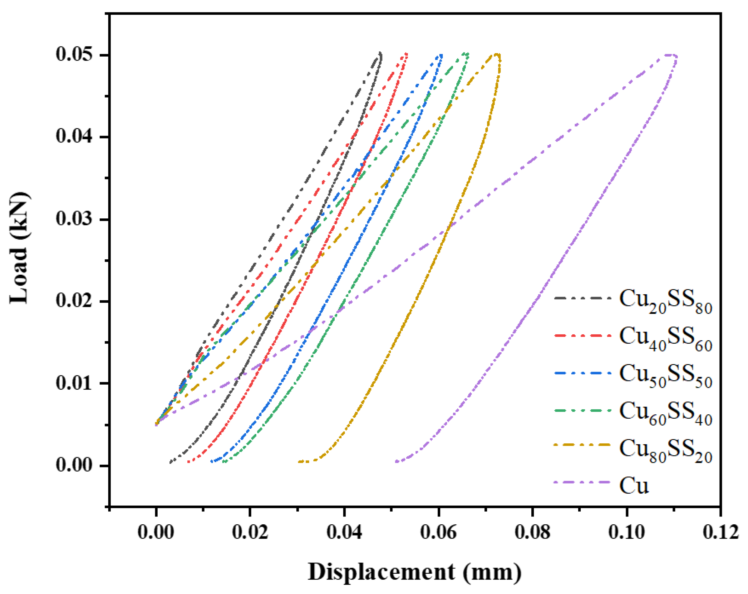
3.4.2. Energy Absorption Capability with Compositions

A single-cycle ABI is conducted to assess the impact of composition on the plastic deformation and energy absorption capability of LDED-built graded walls [24]. Figure 7 presents the load–displacement curve of the single cycle ABI test. The energy stored during deformation can be evaluated by measuring the area under the load–displacement curve. The measured values for the area under the curve, obtained from the load–displacement curve in Cu20SS80, Cu40SS60, Cu50SS50, Cu60SS40, Cu80SS20, and the Cu region are 0.37 N-mm, 0.44 N-mm, 0.59 N-mm, 0.78 N-mm, 1.11 N-mm, and 1.53 N-mm, respectively. As the Cu content increased, the area under the indentation load and displacement curve expanded. This observation indicates a clear correlation between the composition and energy storage capability. An increase in the Cu percentage corresponds to an augmented area under the curve, suggesting a proportional increase in relative energy storage capability as the Cu content increases. Further, measured values of maximum displacement from load-displacement are 0.04 mm, 0.05 mm, 0.06 mm, 0.066 mm, 0.072 mm, and 0.11 mm in Cu20SS80, Cu40SS60, Cu50SS50, Cu60SS40, Cu80SS20, and the Cu region, respectively (as illustrated in Figure 7). An increase in displacement in an ABI test typically indicates greater material ductility or deformability. This increase in displacement can also indicate enhanced toughness or the material’s ability to absorb more energy during deformation.

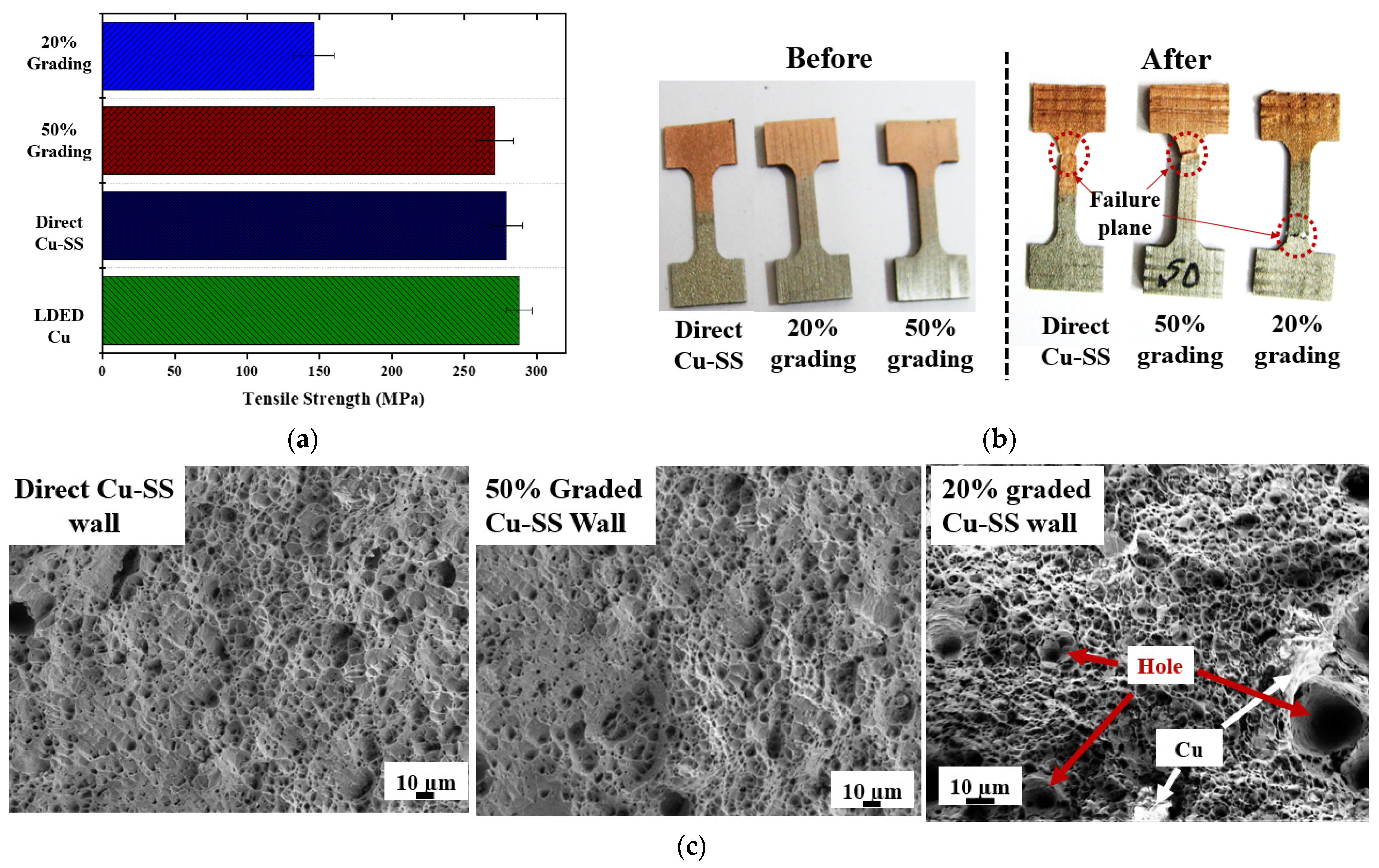
3.4.3. Variation in Ultimate Tensile Strength with Grading

LDED-deposited wall structures are subjected to tensile testing to evaluate the effect of grading on mechanical strength. As mentioned earlier, the tensile sample is prepared in a such way that all the interfaces are accumulated in gauge length (refer to Figure 1c). Figure 8a represents the ultimate tensile strength obtained from the tensile test of LDED deposited Cu, direct Cu-SS wall, 50% FG Cu-SS wall, and 20% FG Cu-SS wall. The evaluated values of ultimate tensile strength are 271 ± 8 MPa, 279 ± 10 MPa and 141 ± 5.5 MPa for LDED deposited direct Cu-SS wall structure, 50% FG Cu-SS wall and 20% FG Cu-SS wall structures, respectively. The tensile strength obtained from the LDED-deposited direct Cu-SS wall structure and the 50% FG Cu-SS wall is close to the strength of LDED-deposited Cu, as depicted in Figure 8a [21]. Moreover, the breaking point occurs in the Cu region for direct Cu-SS wall structure and 50% FG Cu-SS walls during the tensile testing, and in the Fe-rich region (Cu20SS80) for 20% FG Cu-SS wall structures, as shown in Figure 8b. This implies that LDED-built Cu50SS50 and Cu-SS joint yield nearly defect-free deposits in interfaces and blended regions [12]. In addition, it is also observed that the strength of LDED graded wall structures is lower than the strength of graded bulk structures [12]. This can be due to the coarser microstructure in LDED-built walls as compared to fine grains in LDED bulk structures due to reduced cooling rates typically seen in wall structures.
The tensile strength of 20% FG Cu-SS wall structures is lower than the tensile strength of LDED-deposited Cu. The reduced strength and fracture point in the lower Cu region of the LDED-deposited 20% FG Cu-SS wall structures can be ascribed to the existence of micro-cracks or micro-porosity within the Cu20SS80 lower region of the 20% FG Cu-SS wall structures. In addition, this can be due to the softer Cu phase in the inter-dendritic zone offering lower restrictions to dislocation movements causing reduced strength.
SEM is employed to analyze and characterize the morphological features of the fractured surface of the tensile specimen. Figure 8c represents the morphology of the fracture surface of direct Cu-SS wall structure, 50% FG Cu-SS wall and 20% FG Cu-SS wall structures. The presence of scattered dimples on the fractured surface serves as an indicator of ductile failure mode during tensile testing of LDED built graded wall structures. Non-uniformity in the size of dimples can be attributed to the heterogeneous property of the LDED deposited sample due to higher cooling rates and rapid solidification. The presence of deep voids on the fracture surface serves as an indication of trans-granular ductile rupture resulting from the formation of micro-voids and early cracks [25]. This phenomenon leads to reduced tensile strength, as depicted in Figure 8a.

3.5. Sustainability Aspect of LDED Built Graded Wall

It is well established that AM offers minimal wastage of raw material during the fabrication stage of engineering components promoting suitability in manufacturing [26]. Beyond the reduction of raw material wastage, AM empowers the creation of more efficient components, which, in turn, translates into enhanced performance and prolonged component lifespan, thereby ensuring the sustainability of these components throughout their service life [1,26].
In the context of multi-material components, such as Cu-SS, achieving optimal performance becomes a priority. However, when sharp compositional transitions occur at the interface of such components, it often leads to premature component failure and material wastage. This is where compositionally graded Cu-SS components play a crucial role. They not only enhance the component performance by offering a harmonious blend of improved strength, corrosion resistance, and thermal properties but also extend the lifespan of dissimilar components. Fabricating an engineering component with complex geometry using multiple materials is challenging with conventional manufacturing processes. Thus, the fabrication of compositionally graded Cu-SS structures through LDED-based additive manufacturing not only promotes sustainability during the manufacturing phase but also ensures the sustainability of engineering components throughout their service life [27,28]. In addition, the aforementioned utilization of multi-material Cu-SS wall structures presents an opportunity to substitute conventionally manufactured stainless steel fins, leading to enhanced cooling efficiency and reduced dimensions of the fins. This fin offers improved thermal properties of the system due to increased Cu content [29,30]. This leads to enhancement in cooling performance and size reduction of fins and contributes to the development of radiators, chillers, condensers, and more. Thus, LDED of Cu-SS wall structures promotes sustainable manufacturing during fabrication stages and functionality. This approach embodies a holistic commitment to resource efficiency and long-term performance, aligning with broader sustainability goals in the field of manufacturing.

4. Conclusions

In the scope of the present work, LDED of direct Cu-SS, 50%-graded and 20%-graded Cu-SS wall structures is successfully accomplished. From this study, the following conclusions can be derived:
  • Direct Cu-SS and 50%-graded Cu-SS wall structures yield defect deposition at identified parameters.
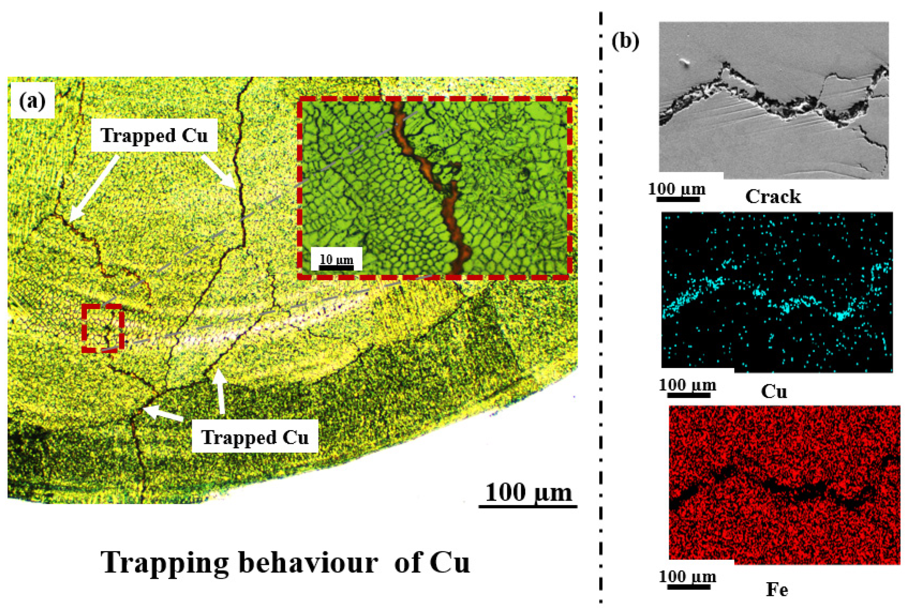
  • Cu-SS wall structures deposited with 20% grading exhibit the presence of micro-cracks and micro-porosity within the Cu20SS80 zone. This occurrence is attributed to the rupture of the thin film of trapped or terminal Cu.
  • LDED built possess columnar grain morphology on Cu region and dendritic-columnar in SS region of blended and graded region due to higher cooling rate. In addition, trapped Cu film or isolated Cu particles offers higher nucleation sites and restrict grain growth of the Fe-rich zone, leading to finer-grain morphology in the Fe-rich zone.
  • Single cycle ABI reveals that increased Cu percentage yields a large area under the load–displacement curve indicating improved deformability capacity and energy storage capacity.
  • Finer-grain morphology leads to higher measured micro-hardness values in the Fe-rich zone and the Cu-rich zone, whereas randomly distributed morphologies of Cu-rich and Fe-rich zones lead to large variations in the measured values of micro-hardness.
  • The assessment of mechanical strength reveals that both the direct Cu-SS wall structure and the 50%-graded Cu-SS wall structure exhibit superior strength as compared to the 20%-graded Cu-SS wall structure.
This study firmly establishes LDED as a robust and viable technique for constructing thin-walled Cu-SS components with graded compositions. These components hold great promise for various applications in industries such as tooling, power generation, and cryogenics.

Author Contributions

Conceptualization, C.P.P. and S.Y.; methodology C.P.P. and A.K.R.; formal analysis, S.Y.; investigation, S.Y. and A.N.J.; resources, C.P.P. and S.K.D.; data curation, S.Y., A.K.R. and A.N.J.; writing—original draft preparation S.Y.; writing—review and editing, A.N.J., A.K.R. and C.P.P.; supervision, C.P.P. and S.K.D.; project administration, S.K.D. All authors have read and agreed to the published version of the manuscript.

Funding

This research was funded by the Department of Atomic Energy, Govt. of India.

Institutional Review Board Statement

Not applicable.

Informed Consent Statement

Not applicable.

Data Availability Statement

The data that support the findings of this study are available on request from the corresponding author.

Acknowledgments

S. Yadav expresses gratitude for the financial support provided by the Raja Ramanna Centre for Advanced Technology (RRCAT), a vital institution under the aegis of the Department of Atomic Energy, Government of India. The authors wish to extend their heartfelt appreciation to P. Ganesh, Shri. Abhijit Chowdhury, Anshu Sahu, V. Bharadwaj, G. K. Mishra, Upendra Kumar, Suresh Kumar, Sokhen Tudu, Lalit, and the dedicated team members of the Laser Additive Manufacturing Laboratory (LAML) at RRCAT, Indore. Their unwavering support and contributions have been instrumental in the successful execution of this research endeavor, and their commitment is sincerely acknowledged.

Conflicts of Interest

The authors declare no conflicts of interest.

References

  1. Paul, C.P.; Sunil Yadav, S.K.; Nayak, A.N.; Jinoop, N.; Bindra, K.S. Is Laser Additive Manufacturing Sustainable? In Sustainability for 3D Printing; Springer International Publishing: Cham, Switzerland, 2021; pp. 29–54. [Google Scholar]
  2. Bhavar, V.; Prakash, K.; Sandeep, T.; Singh, R.K.P. A review on functionally gradient materials (FGMs) and their applications. In Proceedings of the IOP Conference Series: Materials Science and Engineering, Phuket, Thailand, 2–5 August 2017; IOP Publishing: Bristol, UK, 2017; Volume 229, p. 012021. [Google Scholar]
  3. Paul, C.P.; Yadav, S.; Rai, A.K.; Jinoop, A.N.; Bindra, K.S. Laser Directed Energy Deposition based additive manu-facturing of metallic multi-material: A Review. J. Metall. Mater. Sci. 2021, 63, 75–87. [Google Scholar]
  4. Ansari, M.; Jabari, E.; Toyserkani, E. Opportunities and challenges in additive manufacturing of functionally graded metallic materials via powder-fed laser directed energy deposition: A review. J. Mater. Process. Technol. 2021, 294, 117117. [Google Scholar] [CrossRef]
  5. Chakkravarthy, V.; Jose, S.P.; Lakshmanan, M.; Manojkumar, P.; Narayan, R.L.; Kumaran, M. Additive manufacturing of novel Ti-30Nb-2Zr biomimetic scaffolds for successful limb salvage. Mater. Today: Proc. 2022, 64, 1711–1716. [Google Scholar] [CrossRef]
  6. Feenstra, D.; Banerjee, R.; Fraser, H.L.; Huang, A.; Molotnikov, A.; Birbilis, N. Critical review of the state of the art in multi-material fabrication via directed energy deposition. Curr. Opin. Solid State Mater. Sci. 2021, 25, 100924. [Google Scholar] [CrossRef]
  7. Bandyopadhyay, A.; Bryan, H. Additive manufacturing of multi-material structures. Mater. Sci. Eng. R Rep. 2018, 129, 1–16. [Google Scholar] [CrossRef]
  8. Chao, W.; Li, L. Recent progress and scientific challenges in multi-material additive manufacturing via laser-based powder bed fusion. Virtual Phys. Prototyp. 2021, 16, 347–371. [Google Scholar]
  9. Reichardt, A.; Shapiro, A.A.; Otis, R.; Dillon, R.P.; Borgonia, J.P.; McEnerney, B.W.; Hosemann, P.; Beese, A.M. Advances in additive manufacturing of metal-based functionally graded materials. Int. Mater. Rev. 2021, 66, 1–29. [Google Scholar] [CrossRef]
  10. Chen, B.; Su, Y.; Xie, Z.; Tan, C.; Feng, J. Development and characterization of 316L/Inconel625 functionally graded material fabricated by laser direct metal deposition. Opt. Laser Technol. 2020, 123, 105916. [Google Scholar] [CrossRef]
  11. Domack, M.S.; Baughman, J.M. Development of nickel-titanium graded composition components. Rapid Prototyp. J. 2005, 11, 41–51. [Google Scholar] [CrossRef]
  12. Yadav, S.; Paul, C.; Rai, A.K.; Singh, R.; Dixit, S. Elucidating laser directed energy deposition based additive manufacturing of copper-stainless steel functionally graded material: Processing and material behavior. J. Manuf. Process. 2023, 92, 107–123. [Google Scholar] [CrossRef]
  13. Zhang, X.; Pan, T.; Chen, Y.; Li, L.; Zhang, Y.; Liou, F. Additive manufacturing of copper-stainless steel hybrid com-ponents using laser-aided directed energy deposition. J. Mater. Sci. Technol. 2021, 80, 100–116. [Google Scholar] [CrossRef]
  14. Chen, Y.Z.; Liu, F.; Yang, G.C.; Xu, X.Q.; Zhou, Y.H. Rapid solidification of bulk undercooled hypoperitectic Fe–Cu alloy. J. Alloys Compd. 2007, 427, L1–L5. [Google Scholar] [CrossRef]
  15. Articek, U.; Milfelner, M.; Anzel, I. Synthesis of functionally graded material H13/Cu by LENS technology. Adv. Prod. Eng. Manag. 2013, 8. [Google Scholar] [CrossRef]
  16. Zhang, X.; Cheng, S.; Tan, P.; Aaron, F.; Zhang, Y.; Li, L.; Liou, F. Additive manufacturing of copper–H13 tool steel bi-metallic structures via Ni-based multi-interlayer. Addit. Manuf. 2020, 36, 101474. [Google Scholar] [CrossRef]
  17. Noecker, F.F.; DuPont, J.N. Functionally graded copper–steel using laser engineered net shaping™ process. In International Congress on Applications of Lasers & Electro-Optics; AIP Publishing: Long Island, NY, USA, 2002. [Google Scholar]
  18. Rodrigues, T.A.; Bairrão, N.; Farias, F.W.C.; Shamsolhodaei, A.; Shen, J.; Zhou, N.; Maawad, E.; Schell, N.; Santos, T.G.; Oliveira, J.P. Steel-copper functionally graded material produced by twin-wire and arc additive manufacturing (T-WAAM). Mater. Des. 2022, 213, 110270. [Google Scholar] [CrossRef]
  19. Osipovich, K.S.; Astafurova, E.G.; Chumaevskii, A.V.; Kalashnikov, K.N.; Astafurov, S.V.; Maier, G.G.; Kolubaev, E.A. Gradient transition zone structure in steel–copper sample produced by double wire-feed electron beam additive manu-facturing. J. Mater. Sci. 2020, 55, 9258–9272. [Google Scholar] [CrossRef]
  20. Kim, M.J.; Saldana, C. Post-processing of additively manufactured IN625 thin-walled structures using laser remelting in directed energy deposition. J. Manuf. Process. 2023, 88, 59–70. [Google Scholar] [CrossRef]
  21. Yadav, S.; Paul, C.P.; Jinoop, A.N.; Rai, A.K.; Bindra, K.S. Laser directed energy deposition based additive manu-facturing of copper: Process development and material characterizations. J. Manuf. Process. 2020, 58, 984–997. [Google Scholar] [CrossRef]
  22. Prokhorov, N.N. Elements of the metal physics and crystallization process. In Physical Processes in Metals in Welding, 1st ed.; Metallurgy: Moscow, Russia, 1968; Volume 1, p. 695. [Google Scholar]
  23. Guschlbauer, R.; Momeni, S.; Osmanlic, F.; Körner, C. Process development of 99.95% pure copper processed via selective electron beam melting and its mechanical and physical properties. Mater. Charact. 2018, 143, 163–170. [Google Scholar] [CrossRef]
  24. Haggag, F.M.; Hutton, J.T.; Nanstad, R.K.; Swain, R.L.; Thomas, D.L. Use of Automated Ball Indentation Testing to Measure Flow Properties and Estimate Fracture Toughness in Metallic Materials; ASTM International: West Conshohocken, PA, USA, 1990. [Google Scholar]
  25. Bhardwaj, T.; Shukla, M. Effect of Scan Direction on Tensile properties and Fractography of Laser Additive Manufactured Maraging Steel. Mater. Today Proc. 2019, 18, 3842–3848. [Google Scholar] [CrossRef]
  26. Mecheter, A.; Tarlochan, F.; Kucukvar, M. A Review of Conventional versus Additive Manufacturing for Metals: Life-Cycle Environmental and Economic Analysis. Sustainability 2023, 15, 12299. [Google Scholar] [CrossRef]
  27. Colorado, H.A.; Velásquez, E.I.G.; Monteiro, S.N. Sustainability of additive manufacturing: The circular economy of materials and environmental perspectives. J. Mater. Res. Technol. 2020, 9, 8221–8234. [Google Scholar] [CrossRef]
  28. Tang, Y.; Yang, S.; Zhao, Y.F. Sustainable design for additive manufacturing through functionality integration and part consolidation. Handb. Sustain. Addit. Manuf. 2016, 1, 101–144. [Google Scholar]
  29. Mills, K.C. Recommended Values of Thermophysical Properties for Selected Commercial Alloys; Woodhead Publishing: Cambridge, UK, 2002. [Google Scholar]
  30. Dhaou, H.; Ben Khedher, N.; Mellouli, S.; Souahlia, A.; Askri, F.; Jemni, A.; Ben Nasrallah, S. Improvement of thermal performance of spiral heat exchanger on hydrogen storage by adding copper fins. Int. J. Therm. Sci. 2011, 50, 2536–2542. [Google Scholar] [CrossRef]
Figure 1. LDED of Cu-SS wall structures: (a) experimental setup and experimental methodology; (b) schematic of the wall deposition Schematic (c) 2D drawing of the samples used for micro-tensile testing.
Sustainability 16 00519 g001aSustainability 16 00519 g001b
Figure 2. LDED of CG Cu-SS wall structures at three grading percentages (a) as-built wall structures (b) cross-section view.
Sustainability 16 00519 g002
Figure 3. Microstructure showing (a) cracks and Cu trapping (b) elemental composition along the cracks.
Sustainability 16 00519 g003
Figure 4. EDS analysis along the build direction of the Cu-SS wall.
Sustainability 16 00519 g004
Figure 5. Microstructural morphology in LDED-built (a) Cu region, (b) SS region, or blended region and (c) BSE of microporosity in lower Cu region.
Sustainability 16 00519 g005
Figure 6. Micro-hardness variation across LDED built graded Cu-SS walls.
Sustainability 16 00519 g006
Figure 7. Load–displacement curve of single cycle ABI indentation across the different regions of blended compositions.
Sustainability 16 00519 g007
Figure 8. Tensile test of graded Cu-SS wall (a) UTS (b) representative of tensile coupon before and after test (c) fractography of fractured surface of three graded sample.
Sustainability 16 00519 g008
Table 1. Process parameter used for LDED of different blended compositions.
S. NoCompositionsLaser Power (W)Scan Speed (m/min)Powder Feed Rate (g/min)
1Cu100 SS012000.38
2Cu80 SS2012000.58
3Cu60 SS4010000.38
4Cu50 SS5010000.38
5Cu40 SS608000.38
6Cu20 SS808000.38
Disclaimer/Publisher’s Note: The statements, opinions and data contained in all publications are solely those of the individual author(s) and contributor(s) and not of MDPI and/or the editor(s). MDPI and/or the editor(s) disclaim responsibility for any injury to people or property resulting from any ideas, methods, instructions or products referred to in the content.

