Article

An Algorithm to Minimize Near-Zero Rebar-Cutting Waste and Rebar Usage of Columns

Department of Architectural Engineering, Kyung Hee University, Yongin-si 17104, Gyeonggi-do, Republic of Korea
*
Author to whom correspondence should be addressed.
Sustainability 2024, 16(1), 308; https://doi.org/10.3390/su16010308
Submission received: 12 October 2023 / Revised: 7 December 2023 / Accepted: 26 December 2023 / Published: 28 December 2023
(This article belongs to the Special Issue Shaping towards Sustainability in Architecture and Civil Engineering)

Abstract

:
Rebar usage and cutting waste contribute significantly to global greenhouse gas emissions, mainly CO2 and CH4. Researchers have explored various means to minimize cutting waste; however, these studies have yet to address reducing splices and utilizing a single specific special-length rebar. Hence, this study proposed an algorithm to minimize rebar usage and reduce rebar-cutting waste to less than 1% (near-zero rebar-cutting waste). The algorithm involves two main steps: (1) reducing the number of splices by utilizing special-length rebar and (2) adjusting the rebar accordingly based on the obtained special-length rebar. The algorithm was applied to the column rebars of an RC building to validate its effectiveness. The results confirmed a reduction in rebar usage by 3.226 tons (17.76%), a cutting waste rate of 0.83% (near-zero rebar-cutting waste achieved), a reduction of 11.18 tons in CO2 emissions, and a cost reduction of USD 3741. Employing the proposed algorithm in RC building and structure projects will amplify the corresponding benefits and contribute to the achievement of SDGs adopted by the United Nations to ensure sustainable resource usage and the acceleration of sustainable and green construction practices.

Graphical Abstract

1. Introduction

Greenhouse gas (GHG) emissions pose a real threat to the environment, causing global warming and climate change. According to the US Environmental Protection Agency [1], GHGs comprise 79.4% CO2, 11.5% CH4 (methane), 6.2% N2O (nitrous oxide), and 3% fluorinated gases. The construction industry is a major contributor to GHG emissions, with excessive steel reinforcement bar (rebar) usage and cutting waste generating significant carbon emissions globally [2]. In 2019, global rebar-cutting waste reached 47.3 million tons, equivalent to 16.2 million tons of CO2 emissions [3], wasting a tremendous amount of energy for nothing. High amounts of rebar-cutting waste can end up in landfills if not properly managed and disposed of. When rebar pieces end up in landfills, they can indirectly contribute to the production of landfill gas (LFG). Improperly disposed of cutting waste can end up in landfills, where it may be mixed with other types of waste, such as general waste. The presence of rebar-cutting waste within the landfill can exacerbate the generation of LFG by entrapping moisture and increasing the temperature of the surrounding waste, consequently accelerating the decomposition process [4]. LFG is mainly composed of 40–50% CO2 and 50–60% CH4 [5,6], with trace amounts of H2S (hydrogen sulfide) [7]. CH4 is a powerful greenhouse gas (GHG) with a global warming potential 28 times greater than CO2 [7]. The production of each metric ton of rebar requires 304–525 kWh of electricity and 54–96 m3 of fresh water [8] and is further burdened by potential carbon emissions associated with inefficient, non-renewable thermal power plants. Therefore, rebar-cutting waste and rebar usage is a serious threat to the environment. From a construction field viewpoint, employing a rebar unit price of USD 900/ton-rebar [9] and a carbon price of USD 75/ton-CO2 [10], global financial losses resulting from rebar-cutting waste could reach a notable USD 43.8 billion. This figure arises from the substantial production of rebar-cutting waste, estimated at 47.3 million tons, which contributes to approximately 16.2 million tons of CO2 emissions. Thus, minimizing rebar-cutting waste and rebar usage is essential to prevent further financial losses in construction projects and foster sustainable construction practices.
Previous studies predominantly utilized stock-length rebar to create cutting patterns to minimize cutting waste [11,12,13,14,15,16]. Subsequently, with the introduction of special-length (SpL) rebar, some researchers have successfully integrated stock-length and special-length rebars, leading to an even greater reduction in cutting waste [17,18]. However, certain conditions, such as a minimum order quantity, pre-order time, minimum length, and maximum length associated with acquiring SpL rebar, might differ between steel mills [18]. Regarding the lap splice position, most studies examined the lap splice position to optimize rebar-cutting patterns [13,14,15,16,17]. Building codes stipulate lapping zone regulations that govern the position of lap splices during rebar design and arrangement. These regulations are intended to ensure the effective distribution of moment forces within the structure. Researchers [11,12,19] attempted to optimize the lap splice position to reduce rebar-cutting waste in the beam, column, and shear wall. However, despite the adherence, significant cutting waste was still generated (7.2–10.8%). These results imply that the adoption of the lapping zone regulation provided by building codes restricts the effort to reduce the cutting waste. Moreover, construction sites do not strictly adhere to rebar lapping zones in practice due to time-consuming construction procedures, reducing constructability and productivity [20]. Lap splice design in concrete relies on factors like bond strength, cover, confinement, and rebar tensile capacity [21]. Consequently, the lap position within the member is flexible if designed per these factors. Placed beyond the mandated zone, lap splices can still achieve equivalent strength and stability to those placed within [20].
The previous optimization studies [11,12,13,14,15,16,17] limited their study, as they primarily focused on minimizing cutting waste, ignoring the potential for reducing rebar usage through the reduction of the number of splices. In support of this viewpoint, Chen and Yang asserted that the RC design should consider as few splices as possible [19]. Considering the limitations of the previous studies and the potential of placing lap splices beyond the lapping zone, this study proposed a novel algorithm that aimed to minimize rebar usage and obtain near-zero rebar-cutting waste (N0RCW) by reducing the number of splices, allowing flexibility in the positioning of lap splices, and using SpL rebars. The proposed algorithm was verified using longitudinal rebar of continuous columns. This type of column was selected due to its significance as a key structural member in reinforced concrete buildings and its high rebar requirements. In addition, the algorithm’s objective aligns with the Sustainable Development Goals (SDGs) [22] adopted by the United Nations in 2015, particularly SDGs 9, 12, 13, and 15. These goals have a direct or indirect connection with the construction sector [23]. SDG 9 aims to build resilient infrastructure, promote inclusive and sustainable industrialization, and foster innovation; SDG 12 aims to ensure sustainable consumption and production patterns; SDG 13 aims to take serious action to combat climate change and its impacts; and SDG 15 aims to protect and restore land, as well as halt land degradation. Therefore, the application of the proposed algorithm is expected to contribute to the advancement of sustainable, green construction practices and the achievement of the SDGs.
This paper is systematically organized into distinct phases: (1) definition of problems and introduction of novelty; (2) thorough review of existing studies focusing on optimizing rebar-cutting waste and understanding column characteristics; (3) development of the proposed algorithm with detailed methods and procedural steps; (4) comprehensive analysis of rebar-cutting waste, rebar usage, CO2 emissions, and related costs in a case study that applied the proposed algorithm; and (5) in-depth discussion, presentation of findings, results, and insights into future research avenues.

2. Preliminary Study

2.1. Authors’ Related Works

Building codes mandate specific lapping zones for rebar splicing in structural members to ensure the effective distribution of moment forces. However, complying with these regulations can be challenging on construction sites due to various reasons, one of which is the difficulty of meeting the requirements on site. In response to this challenge, researchers conducted experiments and investigations to study the structural stability of members with rebar splices beyond the designated zone. These studies revealed that spliced rebar beyond its designated zone can achieve the same level of structural integrity as those spliced within the designated zone [20]. Furthermore, strict adherence to lap splice regulations leads to the use of more rebars, contributing to increased rebar waste generation. This insight prompted the exploration of disregarding the lap splice position for various structural members, which in this case were columns. While each structural member exhibits reinforcement characteristics that may influence the rebar optimization process, a method was developed to estimate the rebar quantities for columns based on these characteristics [24]. In addition, the special-length-priority concept [18] was developed to further reduce the amount of cutting waste when using stock-length rebar. This study, therefore, incorporated the special-length-priority concept without strict adherence to the lapping zone regulations to reduce the rebar-cutting waste and rebar usage of columns.

2.2. Rebar Optimization Methods

Waste management strategies prioritizing source reduction and prevention offer the greatest efficacy, minimizing resource consumption and adverse environmental impacts [25]. Generally, current rebar optimization methods can be divided into several groups: cutting pattern optimization, utilizing either stock-length or SpL rebar, and lap splice position optimization. These methods can be combined to produce the least amount of rebar-cutting waste and are explained as follows.
The selection of optimal cutting patterns can significantly reduce the trim loss of rebar [11]. Various cutting pattern optimization algorithms were developed to minimize cutting waste, including linear, integer, heuristic, and particle swarm optimization algorithms [18,19,26,27,28]. For example, Chen and Yang [19] employed a linear programming approach to determine the best lapping pattern by using stock-length rebar. Khalifa et al. [29] compared integer programming with a genetic algorithm and found that the genetic algorithm is more effective in reducing rebar-cutting losses. Porwal and Hewage [26] and Lee et al. [18] employed a heuristic approach to analyze the optimal combination of rebar. Both aforementioned studies integrated practical measures and imposed constraints to efficiently generate optimal cutting patterns. In addition, Porwal and Hewage [26] introduced the utilization of SpL rebar to obtain the optimal rebar-cutting patterns. Li et al. [27] went further by developing a novel approach focused on Design for Manufacture and Assembly to optimize rebar design using BIM and a hybrid metaheuristic algorithm. Finally, Ren et al. [28] developed a particle swarm optimization algorithm to optimize the rebar-cutting scheme.
In terms of the lap splice position, most studies considered the fixed position of lap splices [13,14,15,16,17], which restricts the potential of reducing cutting waste. Nadoushani et al. [11,12] optimized the lap splice position within the regulated lapping zone by building codes, such as ACI. However, their effort still resulted in cutting waste of 7.2% for columns and 10.6% for shear walls [11,12]. Chen and Yang [19] attempted to reduce the cutting waste of rebar with lap splice position optimization of a beam, yet resulted in 8.4% cutting waste. The design of lap splices in concrete structures depends on crucial factors, such as the concrete–steel bond, concrete cover, confinement provided by the transverse reinforcement, and rebar tensile strengths [21]. Hence, as long as the lap splice is designed following these factors, the location of the lap splice can be varied within the structural member. Furthermore, as asserted by Widjaja et al. [20], providing lap splices beyond the regulated lapping zone can still provide an equivalent level of structural strength and stability.
A few studies optimized rebar-cutting patterns for the last optimization method by prioritizing SpL rebar over stock-length rebar [17,18]. Lee et al. [18] minimized the rebar-cutting waste by prioritizing SpL rebar over stock length in generating the rebar-cutting patterns. However, Lee et al. [18] generated several SpL rebars, which is not favorable as steel mills usually impose quite strict minimum requirements for purchasing, leading to a limitation on rebar length.
Besides the mentioned approaches, numerous previous studies on optimizing rebar have integrated building information modeling (BIM) to construct the structural model and gather rebar information [11,12,14,26]. BIM models can store geometric data and other information and allow for automatic updates and regeneration of information when modifications are made to the model [30]. This ensures project consistency and coordination throughout the project’s life cycle. Nadoushani et al. [11,12] employed a BIM-produced rebar-cutting list to generate optimized lapping patterns and cutting patterns and minimize trim loss. Using linear programming, the rebar-cutting list obtained from BIM was used to reduce rebar waste [14]. Porwal and Hewage [26] integrated BIM into rebar-waste optimization during the design phase.
Efforts to minimize rebar-cutting waste have been a focus of sustainable construction practices. However, there has been an absence of research on reducing rebar usage as a means to promote sustainable construction. Given the immense worldwide demand for steel and rebar, the reduction in rebar usage would result in a decrease in carbon emissions through the entire production and installation process. Therefore, this study attempted to develop a novel approach that reduces the number of lap splices and uses SpL rebar, which can significantly reduce rebar usage while also achieving N0RCW.

2.3. Column Rebar Characteristics

Columns serve as the main components of the structural frame, where they are specifically designed as vertical load-bearing elements that support axial compressive loads [31]. They play a crucial role in transferring the overall loads from beams to the foundation while ensuring the stability of the structure [32]. The main rebars within continuous columns consist of dowel bars, which establish connections between the foundations and columns, longitudinal rebars that are repetitively linked through lap splices, and rebars anchored to the top beam, as depicted in Figure 1a. Figure 1b demonstrates the details of the main column rebars: the column’s main bar is firmly anchored to the top beam, the dowel bar is anchored securely to the foundation, and the lap splice is positioned at the bottom of each floor.
Building codes, such as ACI and KDS codes, specify the column’s lapping zone [33,34]. ACI [33] specifies that lap splices are permitted within the center half of the member length. KDS [34] specifies a similar approach in that the lap splices are located within half of the column height from the adjacent floor. Conversely, BS and JGC do not specifically set the lapping zone [35,36]. These codes emphasize avoiding lap splice placement in high-stress areas. Furthermore, JGC states that when lapping in the plastic hinge section is inevitable, the splice zone should be reinforced with transverse reinforcement [36].
Contractors generally lap the main rebars of columns directly above the foundation and above the column–beam joint, as shown in Figure 1b, as it is easily identifiable, which increases contractors’ productivity. However, in practice, contractors may use their judgment to put the lap splice along the column, which might be above or below the column–beam joint or in the lapping zone [20]. This practice is deemed acceptable within the JGC codes [36] if the lap length is designed correctly following the factors outlined by Almeida et al. [21]. As a result, the proposed algorithm of this study, which was based on the flexibility of the lap splice position, can reduce the number of lap splices and place the lap splices along the column. This proposed algorithm can avoid unnecessary rebar usage and rebar-cutting waste.

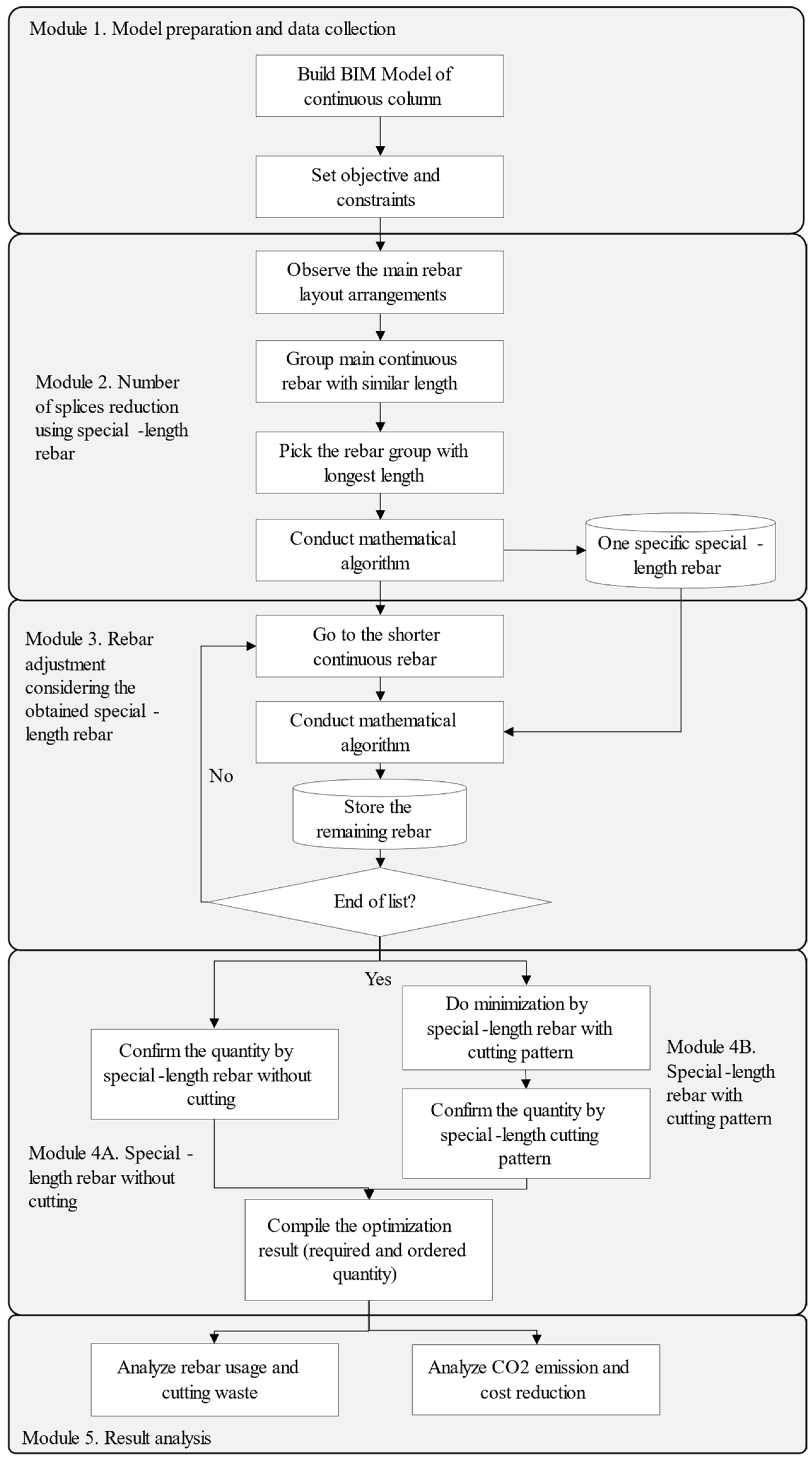
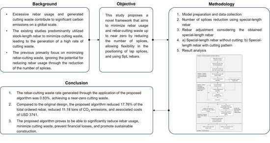
3. Algorithm for the N0RCW and Rebar Usage Minimization

Figure 2 shows the framework of this study. The framework consisted of five modules: (1) model preparation and data collection; (2) the number of splices reduction using SpL rebar; (3) rebar adjustment considering the obtained special SpL rebar; (4) generation of SpL rebar without cutting and SpL rebar with cutting patterns; and (5) results analysis regarding cutting waste, rebar usage, CO2 emission, and cost reduction. The primary focus of the proposed algorithm was minimizing rebar usage and cutting waste, aiming for near-zero by reducing splices, introducing flexibility in the lap splice positions, and employing SpL rebar. This paper presents an algorithm to generate a single SpL rebar that meets steel mills’ minimum quantity and preorder time requirements for SpL rebar procurement. Lee et al. [18] defined the minimum ordered quantity as 50 tons and a two-month lead time for preorders.

3.1. Model Preparation and Data Collection

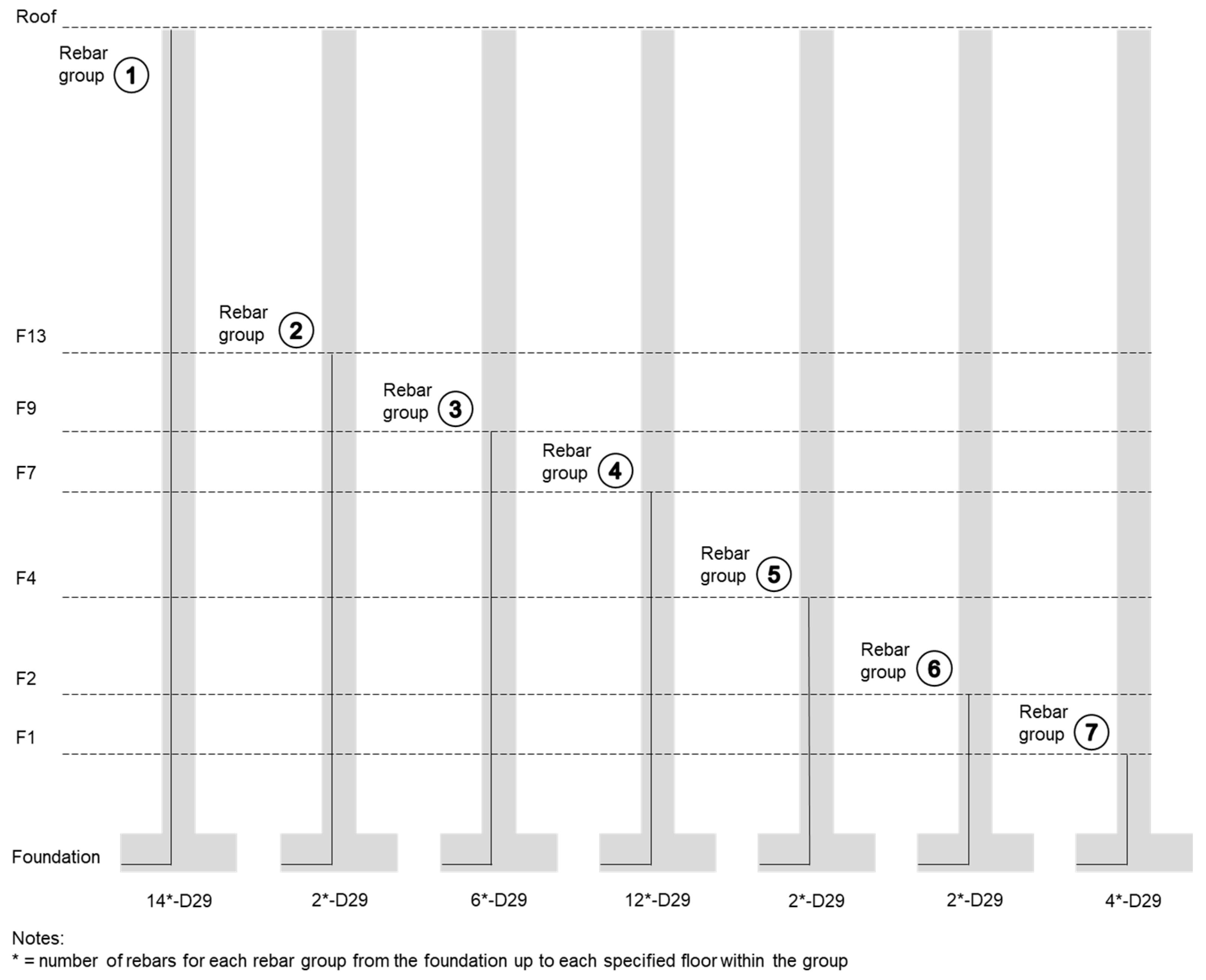
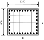
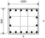
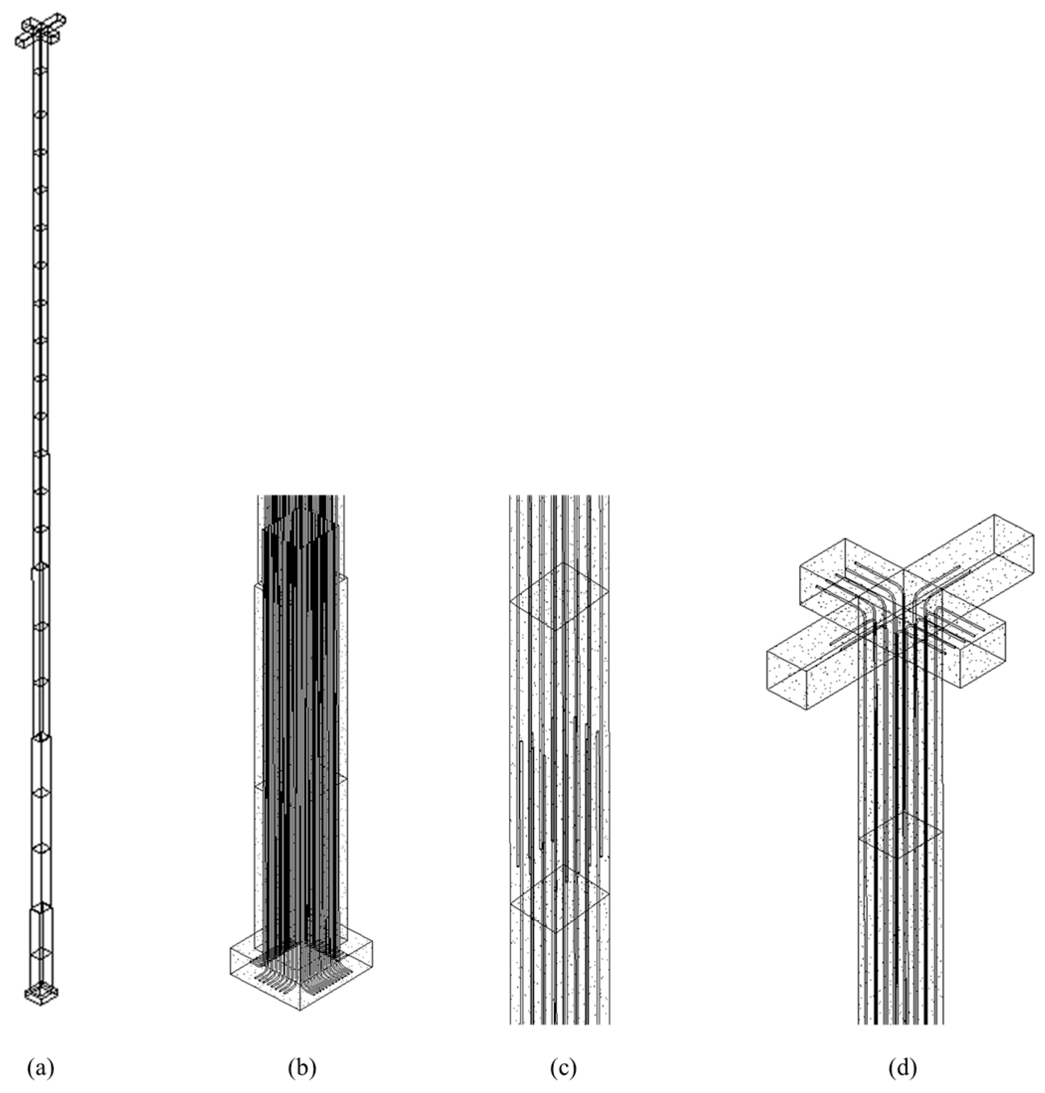
In the first module, the column was built as a structural BIM model in Autodesk Revit following the original structural design. A 3D model was created with the length, width, and depth of concrete columns from the foundation to the roof floor. The reinforcements, which consisted of the main rebar and hoops, were added to the column. From the BIM model, it can be observed that the column exhibited various rebar layout configurations as it extended from the basement floor (B2) to the roof floor, as shown in Table 1. This variation occurred because the column dimensions and the number of rebars decreased on the upper floors. For instance, there were 42 rebars from B2 to B1, whereas there were only 14 rebars from the 13th floor (F13) to the 20th floor (F20).
Based on the observed layout configuration, it can be deduced that certain rebars spanned from the foundation to the roof floor, while others extended only up to a specific point in the column. The proposed algorithm took advantage of this rebar layout by grouping rebars with similar lengths. Consequently, column rebars were classified based on their shared length. For instance, 14 rebars that spanned from the foundation to the roof floor were grouped and labeled as the first rebar group. Similarly, two rebars that spanned from the foundation to the 13th floor (F13) were grouped and referred to as the second rebar group. In this case study, the grouping process was repeated until a total of seven rebar groups were obtained, as shown in Figure 3.

3.2. Number of Splices Reduction Prioritizing SpL Rebar

The second module dealt with the first rebar group, which had the longest length. A series of mathematical algorithms were implemented to reduce the number of splices from the original design. By the end of this module, one specific SpL rebar was obtained.
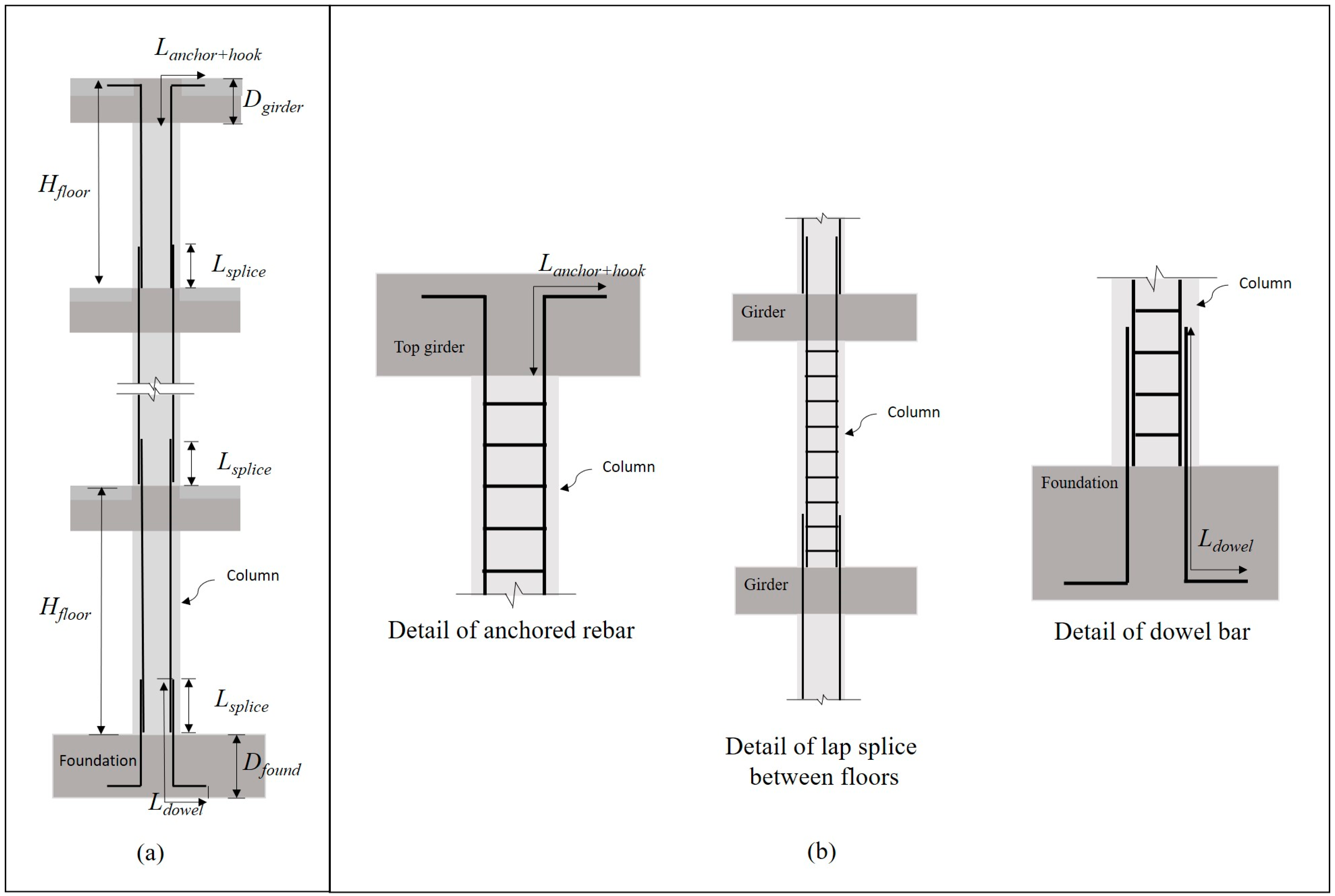
First, rebar information regarding splices ( n s p l i c e ), spans ( n s p a n ), rebars ( n r e b a r ), and the length of lapping ( L l a p ) of the original design needed to be obtained, as it is necessary for the algorithm. Second, the total length ( L t o t a l ) of continuous rebar in the first rebar group was calculated. The total length equation of the column main rebar that stretched from the foundation to the top girder is shown in Equation (1), as proposed in previous research [24]. Equation (1) incorporates the height of the floor, number of floors, depth of girder, length of dowel, length of anchorage, lap length, and number of lap splices.
L t o t a l = 1 n f H f l o o r D g i r d e r + L d o w e l + L a n c h o r + h o o k + L s p l i c e B m a r g i n
where L t o t a l is the total length of continuous main rebar (mm), H f l o o r is the height of each floor (mm), n f is the number of floors for each rebar group, D g i r d e r is the depth of the girder (mm), L d o w e l is the length of the dowel bar (mm), L a n c h o r + h o o k is the hook anchorage length (mm), L s p l i c e is the lap splice length (mm), n s p l i c e is the number of splices, and B m a r g i n is the bending deduction.
Third, the number of SpL rebar was calculated by dividing the total length ( L t o t a l ) by the maximum purchase length ( L m a x ). The number of SpL rebars ( n r e b a r _ s p ) was calculated using the ceiling function to obtain an integer number, as shown in Equation (2).
n r e b a r _ s p = c e i l i n g ( L t o t a l L m a x )
It can be observed that the number of SpL rebars was less than the original number of rebars ( n r e b a r ), which means that the number of splices for an SpL rebar ( n s p l i c e _ s p ) was less than the original number of splices ( n s p l i c e ). Calculation of the number of splices of an SpL rebar ( n s p l i c e _ s p ) was undertaken by reducing the number of SpL rebars by 1, as shown in Equation (3). For example, if the previous equation yielded five SpL rebars, then there would be four splices when considering the SpL rebars (5 − 1 = 4).
n s p l i c e _ s p = n r e b a r s p 1
The difference between the number of splices in the original design and with using SpL rebar led to the reduction in lap splice ( s p l i c e ), which was calculated as shown in Equation (4).
s p l i c e = n s p l i c e n s p l i c e _ s p
The new total rebar length ( L t o t a l _ s p ) should be calculated due to the reduction in the number of splices, as described in Equation (5).
L t o t a l _ s p = L t o t a l ( s p l i c e × L l a p )
The new total rebar length ( L t o t a l _ s p ) was then divided by the number of SpL rebar ( n s p l i c e _ s p ) to acquire the calculated length of the rebar ( L c a l c ), as shown in Equation (6). Then, the calculated length acquired was rounded up to obtain the special-length rebar ( L s p ), as shown in Equation (7). The roundup function was used so that the calculation result was rounded up to one decimal place, as SpL rebar can only be ordered in 0.1 m intervals.
L c a l c = L t o t a l _ s p n r e b a r _ s p
L s p = r o u n d u p L c a l c
Finally, the lapping length was adjusted by using Equation (8).
L a d _ s p l i c e = L s p l i c e + L s p × n r e b a r _ s p L t o t a l n r e b a r _ s p

3.3. Rebar Adjustment Considering the Obtained SpL Rebar

This third module attempted to utilize the SpL rebar obtained from the previous module to accommodate other rebar groups. As dividing the total length of each rebar group by the obtained SpL rebars did not yield an integer value, this step generated a remaining rebar. By the end of the third module, the remaining rebars were collected.
Utilizing Equation (1), the total rebar length ( L t o t a l ) for each rebar group was obtained. The number of rebars ( n r e b a r ) could be calculated by dividing the total rebar length ( L t o t a l ) by the length of the SpL rebar ( L s p ), as described in Equation (9). The ceiling function was used to obtain an integer number. Subsequently, Equation (10) could be employed to calculate the number of SpL rebars for each rebar group.
n r e b a r = c e i l i n g ( L t o t a l L s p )
n r e b a r _ s p j = n r e b a r 1
However, not all rebars could be installed with the obtained SpL rebar. Thus, the remaining rebar ( L r e m a i n i n g ) could be calculated by subtracting the total rebar length ( L t o t a l ) by the total length of SpL rebar that could be installed, as shown in Equation (11). It should be emphasized that the number of remaining rebars will consistently remain at one.
L r e m a i n i n g = L t o t a l n r e b a r _ s p j × L s p

3.4. Quantity Calculation

As shown in Figure 2, the fourth module was about quantity calculation and was divided into two parts. Module 4A was developed to calculate the rebar quantity ( Q r e b a r ) by multiplying the SpL rebar length ( L s p ), number of SpL rebars ( n r e b a r _ s p ), and unit weight of the rebar ( w r e b a r ), as shown in Equation (12). The number of SpL rebars without cutting could be collected from the second and third modules.
Q r e b a r = i = 1 N ( n r e b a r _ s p × L s p   × w r e b a r )
Meanwhile, for module 4B, the number of SpL rebars with cutting patterns ( n r e b a r _ s p ) for the remaining rebars needed to be processed using Equation (13) through Equation (18). These equations were derived from a prior study by Lee et al. [18]. Equation (13) served as the objective function, aiming to reduce the proportion of cutting waste produced by the cutting patterns of SpL rebar.
M i n i m i z e   f X i = i = 1 N L s p i n i l i n i L s p i n i
where L s p i is special length i (mm), l i is the length of cutting pattern i obtained by combining multiple demand lengths (mm), and n i is the number of rebar combinations with the same cutting pattern.
Equations (14)–(18) show the constraints necessary for fulfilling the objective function. In Equation (14), it is required that the length ( l i ) of cutting pattern i gained from the multiple required rebars combination ( r 1 + r 2 + + r n ) should not exceed or equal to the designated special length ( L s p i ). Equation (15) stipulates that the number of rebar combinations sharing the same cutting pattern i ( n i ) must be greater than zero, with i being a positive natural number. Equation (16) specifies that the special length ( L s p i ) must fall within the range of minimum ( L m i n ) to maximum ( L m a x ) of the special length that can be ordered. Equation (17) dictates that the total combined rebar quantity ( Q t o t a l ) must be greater than or equal to the minimum rebar quantity required by the steel mills ( Q s o ). Finally, Equation (18) establishes that the rebar-cutting waste ( ε ) should be less than or equal to the target rebar-cutting waste ( ε t ).
l i     L s p i ,    l i = r 1 + r 2 + + r n
0 < n i ,           i = 1 ,   2 ,   ,   N
L m i n   L s p i   L m a x
Q s o   Q t o t a l
ε = L s p i l i L s p i   ε t
From this module, the required quantity ( Q r e q ) and ordered quantity ( Q o r d ) were obtained based on Equation (12). The required quantity was the actual quantity that was used in the construction, while the ordered quantity was the quantity ordered by the contractors from the steel mills; they were calculated by multiplying the quantity, length, and unit weight of rebar ( w r e b a r ). The required quantity for continuous rebars ( Q r e q c ) could be calculated by considering the calculated rebar length ( L c a l c ) described in Equation (6), as shown in Equation (19), while for the remaining rebars ( Q r e q r ), the quantity could be calculated by considering the total length of the cutting pattern i ( l i ), as described in Equation (20). Equation (21) could be utilized to calculate the ordered quantity for both the continuous and remaining rebars, taking into account the identified SpL rebar ( L s p ). The RCW rate was calculated by dividing the difference between the ordered and required quantities by the ordered quantity, as described in Equation (22).
Q r e q c = n r e b a r _ s p × L c a l c × w r e b a r
Q r e q r = n r e b a r _ s p × l i × w r e b a r
Q o r d = n r e b a r _ s p × L s p × w r e b a r
R C W = Q o r d Q r e q Q o r d × 100 %

3.5. Result Analysis

In the fifth module, the rebar database from the second and third modules, as well as the required and ordered quantities from the fourth module, were compiled. Then, the rebar usage and RCW from the developed algorithm were analyzed and compared with the original design. Finally, the advantages of reducing the number of splices and using SpL rebar were confirmed by comparing the produced CO2 emission and the CO2-associated saving cost with the original design.

4. Validation of the Algorithm

4.1. Case Application

The proposed algorithm was applied to a single continuous column called C14 that spanned from the building’s foundation to its roof floor. A 50-ton minimum order quantity and a two-month preorder period were temporarily disregarded to find the optimal solution for a single continuous column. The building itself comprised a total of 22 floors, with 20 floors located above ground level and 2 basement floors. The column height on each floor varied according to the floor’s specific height. The standard, shortest, and tallest floors were 3800, 3700 mm, and 6000 mm, respectively. More detailed information regarding the column is presented in Table 2. The BIM model of the C14 column that had applied special-length rebar following the proposed algorithm of this study is shown in Figure A1 in Appendix A.
Following the first module, a 3D structural model was built in BIM and the column rebar layout arrangements were observed. In this case study, the main rebar was grouped into seven rebar groups, as shown in Table 3. The illustration of the rebar group division can be seen in Figure 3.

4.2. Number of Splices Reduction

This step attempted to reduce the number of splices from the original structural design. First, rebar information from the original structural design was gathered. For the first rebar group, it was assumed that each floor used one rebar. Hence, there were 22 spans with 22 rebars and 21 splices. The lapping length was 1500 mm. Subsequently, Equation (1) above was used to calculate the total length of the first rebar group. Using the obtained rebar information, a total length of 130,092 mm was obtained.
Then, the number of SpL rebars was calculated using Equation (2). A maximum length of 12 m was used, as it is the maximum stock length that can be provided by steel mills. The result for the number of SpL rebars was 11. This means there were 11 continuous SpL rebars along the C14 column stretching from the foundation to the roof floor. Having 11 SpL rebars also meant there were 10 splices used to install the rebar. The difference in the number of splices with the original design was 11 splices.
Next, the new total rebar length was calculated due to the number of splices reduction. By using Equation (5), the new total rebar length was 113,592 mm. This result was then divided by the number of SpL rebars to acquire the length of the SpL rebars, as shown in Equation (6). This equation resulted in 10.327 m, and it was subsequently rounded up to 10.4 m. Therefore, 11 SpL rebars that were 10.4 m long with 10 splices needed to be installed for one continuous rebar stretch from the foundation to the roof of the C14 column.

4.3. Rebar Adjustment

This step attempted to utilize the obtained SpL rebar from the previous step to other rebar groups. This step generated a remaining rebar for each rebar group because the total length of each rebar group divided by a special length did not result in an integer value.
Take the second rebar group (foundation to the bottom of the 13th floor) for example. Utilizing Equation (1), the total rebar length for the second rebar group was 85.871 m, with 13 splices. The number of rebars for the second rebar group was calculated by dividing the total rebar length by the SpL rebar, as described in Equation (8). As a result, nine rebars with eight splices needed to be installed from the foundation to the bottom of the 13th floor. However, only eight rebars can be installed using a 10.4 m SpL rebar. Thus, the remaining rebar was calculated by subtracting the total length of the SpL rebar that could be installed from the total rebar length, as described in Equation (9). Therefore, eight SpL rebars of 10.4 m and the 2.68 m remaining rebar should be installed in the case of the second rebar group. This process was conducted for other rebar groups, as summarized in Table 4.

4.4. Quantity Calculation

The quantity calculation was conducted by calculating the quantity of SpL rebar without cutting and SpL rebar with a cutting pattern, as explained in module 4. Module 4A was begun by compiling the SpL rebar without cutting from modules 2 and 3. The total number of SpL rebars was obtained by multiplying the number of SpL rebars from one continuous rebar by the number of continuous rebars in each rebar group. Then, following Equation (10), the SpL rebar quantity was calculated by multiplying the total number of SpL rebars with a unit weight of D29 rebar with a value of 5.04 × 10⁻⁶ ton/mm [37]. Table 5 summarizes the quantity of SpL rebar without cutting. The required quantity was obtained by using an SpL rebar of 10.327 m before the ceiling function was applied. The ordered quantity was obtained by using an SpL rebar of 10.4 m, considering that an SpL rebar has to be ordered in 0.1 m intervals.
Next, module 4B was conducted to obtain SpL rebars with cutting patterns for the remaining rebars, as summarized in Table 6. The remaining rebars from the second to the seventh rebar groups were gathered and SpL rebars with cutting patterns were investigated by using Equations (11)–(16). Here, two options of SpL rebars were obtained. Based on calculation results, both options required seven SpL rebars. The first SpL rebar was 10.4 m, which generated 5.71% of rebar-cutting waste, while the second SpL rebar was 10.2 m, which generated the least amount of rebar-cutting waste, which was 3.87%.

4.5. Comparison of the Original Design and Generated Results

4.5.1. Cutting Waste Analysis

Using Equation (22), the cutting waste rate was analyzed using the required and ordered quantities that were obtained using Equations (19)–(21). For the SpL rebars without cutting, a loss rate of 0.57% was obtained. As discussed in previous subsections, SpL rebar procurement potentially results in a loss rate. In the case of using SpL rebars of 10.4 m for SpL rebar with the cutting pattern, the total required quantity to construct the C14 column was 14.815 tons, and the ordered quantity was 14.939 tons, resulting in 0.83% of cutting waste, as shown in Table 7.
In the case of using an SpL rebar of 10.2 m for SpL rebar with the cutting pattern, the total cutting waste was 0.78%, as displayed in Table 8. Both solutions successfully obtained near-zero cutting waste (N0RCW). As both achieved N0RCW, SpL rebar of 10.4 m for SpL rebar with the cutting pattern was used for further analysis since one specific SpL rebar for the whole column C14 is favorable for contractors and steel mills. Furthermore, current minimum requirements require a minimum order quantity of 50 tons to purchase the SpL rebar. Given the insignificant impact of the SpL with the cutting pattern on the overall cutting waste rate, it was difficult to meet the minimum requirements when utilizing two distinct lengths of SpL rebar.

4.5.2. Rebar Usage Analysis

In order to confirm the effectiveness of the proposed algorithm, the quantity from the original design was compared with the quantity of the proposed algorithm. Stock-length rebar of 6 m and 8 m were utilized to calculate the quantity. The detailed quantity calculation of the original design is shown in Table A1 in Appendix A. The total required and ordered quantities of the original design were 15.817 and 18.164 tons, respectively. Thus, there was 12.93% of RCW, which was more than the general assumption of 3%. Conversely, the required and ordered quantities of the proposed algorithm were 14.815 and 14.939 tons, respectively, resulting in 0.83% of RCW. Furthermore, there was a reduction in cutting waste by 2.224 tons or 94.72% when the proposed algorithm was utilized. The obtained result demonstrated a notable reduction in cutting waste to near zero while significantly reducing the rebar usage by 3.226 tons, which was equivalent to 17.76%. Table 9 summarizes the difference between the existing and proposed rebar quantity.

4.5.3. CO2 Emissions and Cost Reduction Analysis

After the near-zero cutting waste was confirmed, a comparison of CO2 emission and cost reduction before and after optimization was conducted. Using 3.466 ton-CO2/ton-rebar [38], the CO2 emission from the actual and optimized rebar quantities was calculated. As a result, the proposed algorithm reduced CO2 emissions by up to 11.18 tons-CO2.
It is important to verify the cost-saving impact by converting the successfully saved rebar to tonnage and CO2 emissions to cost. Hence, the quantity reduction was multiplied by the rebar unit cost (USD 900/ton-rebar) [9] and the CO2 reduction was multiplied by the carbon price reported by the International Monetary Fund (IMF) (USD 75/ton-CO2) [10]. As a result, the rebar cost was reduced by USD 2903 and the carbon cost was reduced by USD 838. The total cost reduction with the proposed algorithm was USD 3741 for column C14. These results demonstrate that reducing the number of splices and utilizing one specific SpL rebar contributed significantly to sustainable construction and cost reduction of construction projects. Table 10 tabulates the reduction rate on the CO2 and CO2-associated cost.

5. Discussion

Sustainable and green construction practices have placed significant emphasis on reducing rebar-cutting waste, as investigated by previous studies [11,12,13,14,15,16,17,18]. Nevertheless, there has been an insufficient focus on reducing rebar consumption. Unnecessary rebar usage commonly occurs when contractors place the lap splice on every floor of the continuous column when the rebar can be continued to the next floor. This practice does not conform to Chen and Yang’s statement. Chen and Yang [19] affirmed that there should be as few splices as possible in designing continuous reinforcements. Therefore, the proposed algorithm of this study emphasizes a number of splices reduction, which can significantly reduce rebar usage. Compared with the original design with a lap splice on every floor, the proposed algorithm used one specific length of SpL rebar, where the lap splice can be placed anywhere along the column. As a result, there was a notable decrease of 17.76% in the total amount of ordered rebar, emphasizing a substantial reduction in rebar consumption.
Regarding cutting waste, the algorithm successfully achieved N0RCW with 0.83% RCW, compared with the 12.93% RCW of the original design, representing a 94.72% reduction. N0RCW is possible due to SpL rebar utilization for rebar with and without cutting patterns. Even after achieving less rebar usage and N0RCW, the algorithm has a limitation. The algorithm is conducted by obtaining predetermined SpL rebar from the rebar group with the longest length and using that SpL rebar in other rebar groups. Hence, for future studies, an algorithm should be developed to be able to obtain one specific SpL rebar without a predetermined SpL rebar. Additionally, the installation of continuous SpL rebar may present certain challenges. To address these challenges, the development of a specialized device to facilitate the installation process, particularly in column–beam or column–girder joints, will be explored in future research.
While reliable and cost-effective, conventional lap splices become longer with increasing rebar diameter. To ensure a good bond, lap splices must be long enough, which can make them costly and impractical. Certain building codes, like the ACI [33], prohibit splicing rebar with a diameter exceeding 36 mm. Couplers of mechanical splices offer an alternative to lap splicing, allowing for connecting these rebar sizes with shorter lap splicing [39], reducing the number of rebars required and rebar waste. Future research could explore the use of couplers to further reduce rebar usage.
Given the immense worldwide demand for steel and rebar, the reduction in rebar usage and cutting waste would result in a reduction in carbon emissions, as well as GHG and cost throughout the entire production and installation process. This study showed that the proposed algorithm was able to reduce CO2 emissions by up to 11.18 tons and the cost by up to USD 3741. This was only for one column, namely, C14. Hence, when the algorithm is applied to a construction project with many columns, the advantages of the algorithm will also be multiplied. Additionally, the reduction of rebar waste conforms with the Sustainable Development Goals (SDGs) adopted by the United Nations in 2015, particularly SDGs 9, 12, 13, and 15. This ensures sustainable rebar usage and helps to tackle the adverse impacts of rebar waste on the environment.
Nevertheless, SpL rebar usage is not yet commonly adopted by the construction industry. One challenge is that steel mills often set difficult requirements, such as a minimum order quantity for a specific SpL rebar. This study demonstrated that obtaining a specific SpL rebar for a single continuous column is possible, requiring 14.939 tons for one column. This was sufficient to meet the minimum order quantity of 50 tons, as the building was constructed of multiple columns. As the authors expect that SpL rebar usage will become more prevalent in the future, it would be advantageous for steel mills to apply more flexible SpL rebar procurement options to make it more accessible to small and medium construction projects. Furthermore, manufacturers of construction materials and products play a critical role in attaining several Sustainable Development Goals (SDGs) targets [40].

6. Conclusions

This paper presents a novel approach for the number of splices reduction and rebar adjustment utilizing special-length rebar, aiming to achieve near-zero rebar-cutting waste and minimize rebar usage. To verify the effectiveness of the proposed algorithm, a continuous column was chosen as a case study. This study highlighted several essential discoveries that contribute to the effort of minimizing rebar-cutting waste and rebar usage, as follows:
  • The obtained results reveal a cutting waste amount of 0.83%, indicating the achievement of near-zero rebar-cutting waste.
  • The algorithm presented led to a reduction of 3.226 tons of rebar, representing a significant 17.76% decrease in the overall ordered rebar quantity. It also resulted in an 11.68-ton reduction in CO2 emissions and lowered the costs by USD 3741.
  • These results highlight the noteworthy potential of the lap splice position optimization, number of splices reduction, and special-length rebar utilization in significantly reducing rebar usage, minimizing cutting waste, promoting sustainable and green construction, contributing to the achievement of Sustainable Development Goals, and preventing further financial losses. Therefore, the discoveries provide insight into significantly reducing cutting waste and rebar usage without impairing the structural integrity or harming the environment.
  • It should be noted that the utilization of special-length rebar is not yet prevalent in the construction industry, partly due to stringent requirements imposed by steel mills, such as a minimum order quantity. This can make it difficult for small and medium construction projects to use special-length rebar, even though a minimum order quantity of 50 tons was met in this case study. Thus, steel mills are encouraged to apply more flexible procurement options for special-length rebar.
Future studies should explore various methods and approaches to further reduce cutting waste and rebar usage, including mechanical couplers. Couplers allow for a connection of two adjacent rebar rods without lap splicing. In addition, the development of a specialized device should also be explored to facilitate the installation process of continuous special-length rebars. Nevertheless, this study demonstrated the feasibility of obtaining a specific special-length rebar for a continuous column. Moreover, the practical application of the proposed algorithm in reinforced concrete buildings and structures that involve numerous columns will further amplify the corresponding benefits.

Author Contributions

S.K.: conceptualization, methodology, validation, resources, data curation, writing—review and editing, supervision, project administration, and funding acquisition. S.L.: conceptualization, methodology, validation, resources, and project administration. D.D.W.: methodology, formal analysis, investigation, writing—original draft preparation, and writing—review and editing. T.S.N.R.: formal analysis, writing—original draft preparation, and writing—review and editing. All authors have read and agreed to the published version of the manuscript.

Funding

This research was funded by the National Research Foundation of Korea (NRF) grants funded by the government of the Republic of Korea (MOE) (no. 2022R1A2C2005276, 2022).

Institutional Review Board Statement

Not applicable.

Data Availability Statement

No new data were created or analyzed in this study. Data sharing is not applicable to this article.

Conflicts of Interest

The authors declare no conflict of interest.

Appendix A

Figure A1. BIM model of column C14. (a) Overall of column C14; (b) the special-length rebar anchored to the foundation; (c) the lap splice of special-length rebar in the middle of the column; (d) the special-length rebar anchored to the top beam.
Sustainability 16 00308 g0a1
Table A1. Quantity calculation of the original design.
FloorFloor HeightLap LengthRequired Length (mm)Preferred Stock Length (mm)Number of RebarRequired Quantity (Ton)Ordered Quantity (Ton)
B2–B13700150052006000421.1011.270
B1–F14600150061008000421.2911.693
F1–F24600150061008000381.1681.532
F2–F35600150071008000361.2881.452
F3–F45600150071008000361.2881.452
F4–F55600150071008000341.2171.371
F5–F65600150071008000341.2171.371
F6–F76000150075008000341.2851.371
F7–F83800150053006000220.5880.665
F8–F93800150053006000220.5880.665
F9–F103800150053006000160.4270.484
F10–F113800150053006000160.4270.484
F11–F123800150053006000160.4270.484
F12–F133800150053006000160.4270.484
F13–F143800150053006000140.3740.423
F14–F153800150053006000140.3740.423
F15–F163800150053006000140.3740.423
F16–F173800150053006000140.3740.423
F17–F183800150053006000140.3740.423
F18–F193800150053006000140.3740.423
F19–F204400150059006000140.4160.423
F20–roof4400150059006000140.4160.423
Total51615.81718.164

References

  1. United States Environmental Protection Agency. Overview of Greenhouse Gases. 2023. Available online: https://www.epa.gov/ghgemissions/overview-greenhouse-gases (accessed on 20 October 2023).
  2. Miller, S.A.; Horvath, A.; Monteiro, P.J.M. Readily Implementable Techniques Can Cut Annual CO2 Emissions from the Production of Concrete by over 20%. Environ. Res. Lett. 2016, 11, 074029. [Google Scholar] [CrossRef]
  3. Kwon, K.; Kim, D.; Kim, S. Cutting Waste Minimization of Rebar for Sustainable Structural Work: A Systematic Literature Review. Sustainability 2021, 13, 5929. [Google Scholar] [CrossRef]
  4. New York State Department of Health. Important Things to Know about Landfill Gas. 2023. Available online: https://www.health.ny.gov/environmental/outdoors/air/landfill_gas.htm (accessed on 4 December 2023).
  5. Hanson, J.L.; Manheim, D.C.; Yesiller, N. Geoenvironmental Assessment of Climate Impacts from Landfill Gas Emissions. Soils Found. 2023, 63, 101279. [Google Scholar] [CrossRef]
  6. United States Environmental Protection Agency. Basic Information about Landfill Gas. 2023. Available online: https://www.epa.gov/lmop/basic-information-about-landfill-gas (accessed on 20 October 2023).
  7. Malmir, T.; Lagos, D.; Eicker, U. Optimization of Landfill Gas Generation based on a Modified First-Order Decay Model: A Case Study in the Province of Quebec, Canada. Environ. Syst. Res. 2023, 12, 6. [Google Scholar] [CrossRef]
  8. Melhem, N.N.; Maher, R.A.; Sundermeier, M. Waste management strategies prioritizing source reduction and prevention offer the greatest efficacy, minimizing resource consumption and adverse environmental impacts. J. Constr. Manag. 2021, 147, 04021056. [Google Scholar] [CrossRef]
  9. Construction Association of Korea. Construction on Hold as Material Prices Go through the Roof. 2022. Available online: https://koreajoongangdaily.joins.com/2022/04/22/business/industry/Inflation/20220422165447730.html (accessed on 17 January 2023).
  10. International Monetary Fund (IMF). Why Countries Must Cooperate on Carbon Prices. 2022. Available online: https://www.imf.org/en/Blogs/Articles/2022/05/19/blog-why-countries-must-cooperate-on-carbon-prices (accessed on 12 January 2023).
  11. Nadoushani, Z.S.M.; Hammad, A.W.; Akbarnezhad, A. A Framework for Optimizing Lap Splice Positions within Concrete Elements to Minimize Cutting Waste of Steel Bars. In Proceedings of the 33rd International Symposium on Automation and Robotics in Construction (ISARC 2016), Auburn, AL, USA, 21 July 2016. [Google Scholar] [CrossRef]
  12. Nadoushani, Z.S.M.; Hammad, A.W.; Xiao, J.; Akbarnezhad, A. Minimizing Cutting Wastes of Reinforcing Steel Bars Through Optimizing Lap Splicing within Reinforced Concrete Elements. Constr. Build. Mater. 2018, 185, 600–608. [Google Scholar] [CrossRef]
  13. Zubaidy, S.; Dawood, S.Q.; Khalaf, I.D. Optimal Utilization of Rebar Stock for Cutting Processes in Housing Project. Int. Adv. Res. J. Sci. 2016, 3, 189–193. [Google Scholar]
  14. Nanagiri, Y.V.; Singh, R.K. Reduction of Wastage of Rebar by Using BIM and Linear Programming. Int. J. Technol. 2015, 5, 329. [Google Scholar] [CrossRef]
  15. Zheng, C.; Yi, C.; Lu, M. Integrated Optimization of Rebar Detailing Design and Installation Planning for Waste Reduction and Productivity Improvement. Autom. Constr. 2019, 101, 32–47. [Google Scholar] [CrossRef]
  16. Khondoker, M.T.H. Automated Reinforcement Trim Waste Optimization in RC Frame Structures using Building Information Modeling and Mixed-Integer Linear Programming. Autom. Constr. 2021, 124, 103599. [Google Scholar] [CrossRef]
  17. Zheng, C.; Lu, M. Optimized Reinforcement Detailing Design for Sustainable Construction: Slab Case Study. Procedia Eng. 2016, 145, 1478–1485. [Google Scholar] [CrossRef]
  18. Lee, D.; Son, S.; Kim, D.; Kim, S. Special-Length-Priority Algorithm to Minimize Reinforcing Bar-Cutting Waste for Sustainable Construction. Sustainability 2020, 12, 5950. [Google Scholar] [CrossRef]
  19. Chen, Y.H.; Yang, T.K. Lapping Pattern, Stock Length, and Shop Drawing of Beam Reinforcements of an RC Building. J. Comput. Civ. Eng. 2015, 29, 04014028. [Google Scholar] [CrossRef]
  20. Widjaja, D.D.; Rachmawati, T.S.N.; Kwon, K.; Kim, S. Investigating Structural Stability and Constructability of Buildings Relative to the Lap Splice Position of Reinforcing Bars. J. Korea Inst. Build. Constr. 2023, 23, 315–326. [Google Scholar] [CrossRef]
  21. Almeida, J.P.; Prodan, O.; Tarquini, D.; Beyer, K. Influence of Lap Splices on the Deformation Capacity of RC Walls. I: Database Assembly, Recent Experimental Data, and Findings for Model Development. J. Struct. Eng. 2017, 143, 04017156. [Google Scholar] [CrossRef]
  22. United Nations Department of Economic and Social Affairs. The 17 Goals. 2023. Available online: https://sdgs.un.org/goals (accessed on 20 October 2023).
  23. Ebekozian, A.; Aigbavboa, C.; Aigbedion, M. Construction industry post-COVID-19 recovery: Stakeholders perspective on achieving sustainable development goals. Int. J. Constr. Manag. 2023, 23, 1376–1386. [Google Scholar] [CrossRef]
  24. Rachmawati, T.S.N.; Widjaja, D.D.; Kim, S. Advancing an Automated Algorithm for Estimating Rebar Quantities in Columns. J. Korea Inst. Build. Constr. 2023, 23, 497–508. [Google Scholar] [CrossRef]
  25. Nikmehr, B.; Hosseini, M.R.; Wang, J.; Chileshe, N.; Rameezdeen, R. BIM-Based Tools for Managing Construction and Demolition Waste (CDW): A Scoping Review. Sustainability 2021, 13, 8427. [Google Scholar] [CrossRef]
  26. Porwal, A.; Hewage, K.N. Building Information Modeling–Based Analysis to Minimize Waste Rate of Structural Reinforcement. J. Constr. Eng. Manag. 2012, 138, 943–954. [Google Scholar] [CrossRef]
  27. Li, M.; Wong, B.C.L.; Liu, Y.; Chan, C.M.; Gan, V.J.L.; Cheng, J.C.P. DfMA-Oriented Design Optimization for Steel Reinforcement Using BIM and Hybrid Metaheuristic Algorithms. J. Build. Eng. 2021, 44, 103310. [Google Scholar] [CrossRef]
  28. Ren, K.; Jia, L.; Huang, J.; Wu, M. Research on Cutting Stock Optimization of Rebar Engineering Based on Building Information Modeling and an Improved Particle Swarm Optimization Algorithm. Dev. Built Environ. 2023, 13, 100121. [Google Scholar] [CrossRef]
  29. Khalifa, Y.; Salem, O.; Shahin, A. Cutting Stock Waste Reduction Using Genetic Algorithms. In Proceedings of the 8th Annual Conference on Genetic and Evolutionary Computation, Seattle, WA, USA, 8–12 July 2006; pp. 1675–1680. [Google Scholar] [CrossRef]
  30. Ali, K.N.; Alhailah, H.H.; Kassem, M.A. Collaboration and Risk in Building Information Modelling (BIM): A Systematic Literature Review. Buildings 2022, 12, 571. [Google Scholar] [CrossRef]
  31. Samarakkody, D.I.; Thambiratnam, D.P.; Chan, T.H.T.; Moragaspitiya, P.H.N. Differential axial shortening and its effects in high rise buildings with composite concrete filled tube columns. J. Constr. Build. Mater. 2017, 143, 659–672. [Google Scholar] [CrossRef]
  32. Hassoun, M.N.; Al-Manaseer, A.A. Structural Concrete: Theory and Design, 7th ed.; Wiley: Hoboken, NJ, USA, 2020; ISBN 978-1-119-60512-6. [Google Scholar]
  33. American Concrete Institute. Building Code Requirements for Structural Concrete and Commentary (Metric), 1st ed.; American Concrete Institute: Farmington Hills, MI, USA, 2014; pp. 1–519. [Google Scholar]
  34. KDS 14 20 52: 2021; Concrete Structure—Joint Design Criteria. Korean Ministry of Land, Infrastructure and Transportation: Sejong, Republic of Korea, 2022; pp. 1–15.
  35. BS 8110-1: 1997; Structural Use of Concrete: Code of Practice for Design and Construction—Part 1. 2nd ed. British Standard Institute: London, UK, 1997; pp. 1–150.
  36. Japan Society of Civil Engineers (JSCE). JSCE Guidelines for Concrete No. 15—Standard Specifications for Concrete Structures—“Design”, 1st ed.; Japan Society of Civil Engineers: Tokyo, Japan, 2007; pp. 1–469. [Google Scholar]
  37. Dongguk Steel. Reinforcing Bars. 2023. Available online: https://www.dongkuksteel.com/en/product/rebars_basic (accessed on 12 January 2023).
  38. Korea Institute of Construction Technology (KICT). The Environmental Load Unit Composition and Program Development for LCA of Building: The Second Annual Report of the Construction Technology R&D Program; Korean Institute of Construction Technology: Goyang, Republic of Korea, 2004; Available online: https://scienceon.kisti.re.kr/srch/selectPORSrchReport.do?cn=TRKO201000018952 (accessed on 17 January 2023).
  39. Bompa, D.V.; Elghazouli, A.Y. Ductility of Reinforced Concrete Members Incorporating Mechanical Splices. In Proceedings of the 16th European Conference on Earthquake Engineering (16ECEE), Thessaloniki, Greece, 18–21 June 2018; Available online: https://www.researchgate.net/publication/328805138_Ductility_of_reinforced_concrete_members_incorporating_mechanical_splices (accessed on 20 October 2023).
  40. Secher, A.Q.; Collin, C.; Linnet, A. Construction Product Declarations and Sustainable Development Goals for Small and Medium Construction Enterprises. In Proceedings of the 25th CIRP Life Cycle Engineering (LCE) Conference, Copenhagen, Denmark, 30 April–2 May 2018; pp. 54–58. [Google Scholar] [CrossRef]
Figure 1. (a) Common main rebar arrangement of the column; (b) detail of column rebar arrangement (adapted from Rachmawati et al. [24]).
Sustainability 16 00308 g001
Figure 2. Algorithm framework for N0RCW and rebar usage minimization.
Sustainability 16 00308 g002
Figure 3. Rebar groups that shared similar lengths (adapted from Rachmawati et al. [24]).
Sustainability 16 00308 g003
Table 1. Rebar arrangement of each section (adapted from Rachmawati et al. [24]).
FloorsB2-B1F1F2-F3F4-F6
C14Sustainability 16 00308 i001Sustainability 16 00308 i002Sustainability 16 00308 i003Sustainability 16 00308 i004
Concrete strength, fc (MPa)35353535
Dimension (mm)1400 × 11001200 × 11001200 × 10001200 × 800
Reinforcement42–UHD2938–UHD2936–UHD2934–UHD29
HoopsBoth endsHD10@300HD10@150HD10@150HD10@150
CenterHD10@300HD10@300HD10@300HD10@300
FloorsF7-F8F9-F12F13-F20
C14Sustainability 16 00308 i005Sustainability 16 00308 i006Sustainability 16 00308 i007
Concrete strength, fc (MPa)353535
Dimension (mm)1000 × 8001000 × 8001000 × 800
Reinforcement22–UHD2916–UHD2914–UHD29
HoopsBoth endsHD10@150HD10@150HD10@150
CenterHD10@300HD10@300HD10@300
Table 2. Data of column and its reinforcement.
DescriptionContents
Foundation depth ( D f )600 mm
Foundation concrete cover ( C f )50 mm
Basement level (B2–B1) height8300 mm
Upper ground level (F1–roof) height87,400 mm
Total floor height ( H f l o o r ) 95,700 mm
Girder depth ( D g i r d e r )700 mm
Rebar diameter ( d )UHD600 D29
Concrete strength ( f c )B2-F20: 35 MPa
Girder depth ( D g i r d e r )700 mm
Lap splice length ( L s p l i c e )1500 mm
Anchorage length ( L a n c h o r )1050 mm
90-degree hook length ( L h o o k )350 mm
Dowel bar length ( L d o w e l )2350 mm
Bend deduction ( B m a r g i n )79 mm
Table 3. Rebar groups with a similar total length.
Rebar GroupFloorsNo. of Continuous Rebars (pcs)Total Height of Floor (mm)
1stB2–roof1495,700
2ndB2–F13264,100
3rdB2–F9648,900
4thB2–F71241,300
5thB2–F4224,100
6thB2–F2212,900
7thB2–F148300
Table 4. Summarization of rebar adjustment and obtained remaining rebars.
Rebar GroupFloorsTotal Length (mm)Number of SpL Rebars (pcs)Length of Remaining Rebar (mm)
2ndB2–F1385,87182680
3rdB2–F964,67162280
4thB2–F754,07152080
5thB2–F432,37131180
6thB2–F218,17117780
7thB2–F112,07111680
Table 5. Quantity calculation of SpL rebar without cutting.
Rebar GroupFloorNumber of Continuous Rebars (pcs)No. of SpL Rebars per One Continuous RebarTotal No. of SpL Rebars (EA)Required Quantity (Ton)Ordered Quantity (Ton)
1stB2–roof14111548.0158.072
2ndB2–F1328160.8330.839
3rdB2–F966361.8741.887
4thB2–F7125603.1233.145
5thB2–F42360.3120.314
6thB2–F22120.1040.105
7thB2–F14140.2080.210
Total14.46914.572
Table 6. SLP combination of the remaining rebars.
Length (mm)Number (pcs)Required Quantity (Ton)Ordered Quantity (Ton)Cutting Waste (%)
10,40070.3460.3675.71%
10,20070.3460.3603.87%
Table 7. Cutting waste analysis utilizing 10.4 m of SpL rebar.
DescriptionSpL Rebar (m)Required Quantity (Ton)Ordered Quantity (Ton)Cutting Waste (Ton)Loss Rate (%)
SpL rebar without cutting10.414.46914.5720.1030.71%
SpL rebar with cutting pattern10.40.3460.3670.0215.71%
14.81514.9390.1240.83%
Table 8. Cutting waste analysis utilizing 10.2 and 10.4 m of SpL rebars.
DescriptionSpL Rebar (m)Required Quantity (Ton)Ordered Quantity (Ton)Cutting Waste (Ton)Loss Rate (%)
SpL rebar without cutting10.414.46914.5720.1030.71%
SpL rebar with cutting pattern10.20.3460.3600.0143.87%
14.81514.9320.1170.78%
Table 9. Comparison of the original design and proposed algorithm.
DescriptionRequired Quantity (Ton)Ordered Quantity (Ton)Cutting Waste (Ton)RCW Rate (%)
Original design (O)15.81718.1642.34812.93
Proposed algorithm (P)14.81514.9390.1240.83
Reduction (O-P)1.0023.2262.22412.10
Reduction rate (O-P)/O6.33%17.76%94.72%93.58%
Table 10. Comparison of CO2 emission and cost reduction.
DescriptionQuantity (Ton)CO2 Amount (Ton)Rebar Cost (USD)Carbon Cost (USD)Total Cost (USD)
Original (O)18.16462.9616,348472221,070
Proposed (P)14.93951.7813,445388417,329
Reduction (O-P)3.22611.1829038383741
Disclaimer/Publisher’s Note: The statements, opinions and data contained in all publications are solely those of the individual author(s) and contributor(s) and not of MDPI and/or the editor(s). MDPI and/or the editor(s) disclaim responsibility for any injury to people or property resulting from any ideas, methods, instructions or products referred to in the content.

