Abstract
Electric vehicles (EVs) are set to become one of the domestic transportation systems that are highly preferred over conventional vehicles. Due to the huge demand for and cost of fuel, many people are switching over to EVs. Companies such as Tesla, BMW, Audi, and Mercedes have started marketing EVs. These EVs need charging stations to charge the batteries. The challenges for EV batteries require the implementation of features such as fast charging, long-run utilization, reduced heat emission, a light weight, and a small size. However, fast charging using conventional converters generates an imbalance in current injection due to the passive component selection. In this study, a converter is proposed that uses an interleaved network that provides a balanced current injection; i.e., an improved interleaved phase-shifted semi-bridgeless boost converter (IIPSSBBC) is designed for EV battery charging applications. The suggested approach is mathematically designed using MATLAB/Simulink (2021) software. The result shows that the battery charging current achieves about 16.5 A, which is relatively more than conventional systems. Moreover, the charging time of the proposed converter is about 6 hrs for a 50 Ah battery with a discharge load capacity of 5000 W, which is relatively less than the conventional method. In a nutshell, compared with conventional converters, the IIPSSBBC performs better, and, notably, the charging speed and current injection are increased by two times the amount. Further, a prototype hardware model is developed to assess the performance of the proposed converter.
1. Introduction
At present, hybrid and electric vehicles have grasped extensive attention across the world due to continuous developments in energy storage systems, power electronic converters, motor drives, and appropriate control theories [1]. Moreover, the private transportation domain has been progressively increasing for a few years, with more than 20 million vehicles in Europe [2]. In particular, the upsurge in demand for clean resources requires scholars of power electronics to develop substitutes for internal combustion engine (ICE) cars [3]. The technological development of traditional ICEs is not sufficient to resolve the concerns associated with the carbon emissions produced by road vehicles. Therefore, long-term sustainable mobility can only be guaranteed by adopting novel technologies, which need to be competent before being presented to the market. Battery electric vehicles (BEVs) are a striking substitute for the current ICE vehicles due to their lower ecological influence and zero emissions. Nonetheless, BEVs are a less mature expertise, with huge restrictions on enhancements, specifically on electric drives and segments of energy storage devices [4]. However, the effective positioning of EVs hinges on numerous crucial elements, such as cost optimization, government policies, and range increase. In particular, the core price difference between ICE vehicles and EVs originates from vehicle powertrains, such as the motor and battery, the ancillary price tag associated with research and development, and administration activities. More specifically, about 60.0% of material costs are from the total battery cost, and roughly 52.0% are from the permanent magnet motor price [5].
Globally, electric vehicles (EVs) are one of the fastest emerging technologies. The Global Electric Vehicle Outlook [6] forecasted in the year 2021 states that the volume of electric cars on the road will be about 16.5 million, which is thrice that of the current scenario. Due to the high demand for EVs, manufacturers are concentrating on developing research on charging and battery technology; in particular, onboard charging (OBC) is the better choice due to its simplicity [7]. Notably, distributed generations (DGs) are becoming a prominent option for incorporating energy distribution due to their economic, environmental, and technical advantages [8] that could help to advance renewable-based EV charging stations. Fossil-fuel-based energy production causes a surge in the release of greenhouse gases that exacerbate ecological circumstances due to effluence elements [9,10,11]. Many research articles have been published related to distributed energy, DC/DC converters, disturbance systems, and DC motor drives. For the converting technique, the conventional diode bridge AC-to-DC converter is replaced by a bridgeless converter to reduce conduction losses. Voltage regulation can be carried out using a DC/DC converter connected between the inverter and energy storage device in the powertrain of an EV and a hybrid EV, and it can stabilize the DC bus voltage [12]. Additionally, a DC/DC converter facilitates the provision of the bidirectional energy transaction ability to capture the regenerative power production that can be stored in the battery banks. Furthermore, some of the applications in EVs may entail overlapping input–output voltage choices. A bridgeless DC/DC converter with power factor correction (PFC) is necessary to limit the harmonic level on the AC side as per IEC standards [13]. Moreover, unlike the continuous conduction mode of operation, the discontinuous current conduction mode of operation of the converters is reliable, cost effective, and robust, and it also eliminates the phase-locked loop (PLL).
Some of the converter approaches are intended to function in the discontinuous capacitor voltage mode (DCVM) in order to accomplish a small total harmonic distortion (THD) and an incessant current on the input side with the simplest assembly. The DCVM procedure offers added benefits, namely, low turn-off losses, a reduced complexity, and an intrinsic PFC of the controller circuit. Unlike a buck converter, this type of converter eradicates the dead angle of the current on the input side without involving any additional circuits. Likewise, the efficiency of the converter is enhanced by removing the two-input diodes in the energy-passing footpath. The total switching loss can be avoided by attaining nearly zero-current switching (ZCS) during turn-on and nearly zero-voltage switching (ZVS) during turn-off.
This research work is structured as follows: Section 2 provides a summary of the recent works in the literature. Section 3 presents the proposed system and its modes of operation. Section 4 presents the results and discussion of both the simulations and the hardware prototype model. Finally, Section 5 concludes the research work.
2. Related Works
Considering the working background of this paper, a robust literature review is performed to assess the performance and application of various converting topologies.
A buck-boost-based switched-mode bridgeless AC/DC was adapted by Dixit A et al. [14] with orthodox rectifier units, and their associated losses can be eliminated using this bridgeless topology. It operates under the discontinuous current conduction mode (DCCM), therefore attaining natural PFC for an adjustable alternating current input. The control is modest due to the engagement of a solitary sensor and the removal of a phase-locked loop. The experimental outcomes were investigated using a 1 kW prototype hardware model. Further, Pandey R et al. suggested a canonical switching cell (CSC) converter, which was found to increase the ripple of the output voltage and provide an increased power quality in the conventional battery chargers of e-rickshaws [15]. It operates in the continuous inductor conduction mode (CICM) to comprehend PFC and a half-bridge converting element-based DC/DC converter structured by pulse width control (PWM).
An improved PFC rectifier and ZVS-ZCS DC/DC high-frequency converter were recommended by Kanimozhi G et al. [16], which comprised an effective dual-step charging network and a current-based DC/DC switching converter. This controller achieved a non-linear converter switching regulator that showed high robustness, a faster transient response, and noise rejection on the input side. It also improved the efficiency of the battery charger by reducing the losses when switching decreasing the stresses on the voltage that reversing the diode’s recovery losses. Further, the simulation and hardware results suggested that the charging (overall) efficiency increased by about 96.50%; 3% greater than that of the traditional dual-step methodology employing an interleaved converter. Additionally, Ortiz-Castrillion et al. [17] suggested a sliding-surface-based semi-bridgeless boost converter that had a novel sliding surface to regulate semi-bridgeless boost converters that concurrently achieve PFC and the regulation of the DC bus. It was the first controlling approach that did not require a cascaded PI/hybrid PI-sliding mode mechanism for instantaneously governing DC and AC voltages. Moreover, it gave superlative dynamic performance by eliminating DC overvoltages. Further, an examination of the stability of the projected start-up (surface) against huge perturbations was accomplished.
Several converter cells have been demonstrated to show particular configuration interpretation procedures, and the enactment of the resultant shortened configurations has been studied using bridgeless PFC configuration simplification and design [18]. To offer an unbiased quantitative configuration considering volume, cost, and power loss, this work introduced a reliable element-database-based model process. Then, the outcomes were investigated to provide options for various configurations. Further, Lapez-Santos et al. [19] proposed an isolated bridgeless SEPIC high PFC rectifier with an examination and plan of a sliding-mode-based regulator to attain a high PFC in the bridgeless inaccessible form of the single-ended primary inductor converting operation. It was employed as a bi-directional isolated interaction between a low-voltage DC distribution bus and an AC source. To safeguard the tracing of a high-quality current reference on the input side, the sliding-mode regulation was adopted, which was attained through a sine waveform function generator coordinated with the power network. Then, a pulse-density modulation for semi-bridgeless active rectifiers was proposed with an enriched pulse-density modulation energy regulation technique in an inductive energy transfer scheme [20]. The features of ZVS and ZCS for the SBAR’s switches could also be attained with the anticipated technique to regulate the gate signals using the synchronization governor. Then, the hardware prototype model with four paralleled pickups warranted the suggested technique.
The semi-bridgeless interleaved PFC boost rectifier also recommended by the authors in [21] had a front-end converter for plug-in hybrids. The projected approach achieved a greater efficiency with a greater input power factor and a smaller amount of power drained from the utility. The reformed converter configuration attained a greater efficiency, namely, 97.0%, as it removed the bridge rectifier and the accumulation of slow diodes. Experimental fallouts suggested that the power factor was 0.999 with fewer than 5.0% THD when the load was regulated from one state to another (half to full load state). Further, Khalid et al. [22] proposed a multi-pulse converter-based rectification scheme with an off-board configuration for EV charging. It employs a model of multi-pulse converters for EV charging that increases the power quality of the derived line current. The projected configuration works on a tie-line power grid frequency and neglects the usage of high-frequency switches, consequently taming the efficiency and diminishing the intricacy of the complete charging system. The EV charging configuration was developed in MATLAB/Simulink to assess the power quality parameters using THD in the input line current and power factor.
A bi-directional power charging control strategy was introduced with the charging control characteristic of the batteries associated with the power grid, instantaneously adjusting the voltage and frequency of the grid for a 24 h period [23]. The observed outcomes proved the soundness of the anticipated control approach during the synchronization of a plug-in hybrid EV, with a substantial peak reduction and power quality enhancement. Moreover, Ramesh Kumar T et al. [24] reported a matrix converter (MC) to assess the mechanical and electrical features of a wind energy system using two distinct schemes. The input filters with the MC were engaged to improve the efficiency of the arrangement with a condensed harmonic substance involved in the power network. The observed outcomes revealed the competence of the MC with the input filter, achieving an important range of 95.75% and outpacing other conventional converting practices. Moreover, Rajalakshmi et al. [25] developed a simplified high gain quasi-boost inverter (SHGqBI) to eradicate the weaknesses of conventional schemes. The anticipated inverter condensed the extra modules that could reduce the size of the model with condensed losses during conduction and switching. The THDs of the current and voltage of the suggested inverter were logged, showing estimable scales of 2.70% and 10.20%, respectively.
Based on the aforementioned analyses, it can be seen that various topologies have been adapted to boost operations in different applications. Considering the outcomes of these topologies, there is a strong need to improve the charging characteristics of onboard battery chargers, but an improved power modulator is required. Moreover, the power modulator must be lightweight and have more backup power supplies. Henceforth, an improved interleaved phase-shifted semi-bridgeless boost converter is modeled for EV charging stations, and it is expected that this model can provide the performance required for EV applications.
In this paper, an improved interleaved phase-shifted semi-bridgeless boost converter (IIPSSBBC) is designed for EV battery charging applications. The suggested approach is mathematically designed using MATLAB/Simulink 2021. Compared with conventional converters, IIPSSBBC has an additional control topology that injects the current by sharing the interleaved stages. The current imbalance during the cycles of charging can be overwhelming. Thus, the performance of the proposed converter triggers a charging speed and a current injection that have about twice the range of those of the conventional one. Further, a prototype hardware model is developed to assess the performance of the proposed converter.
3. Proposed System and Modes of Operation
The proposed system consists of various sources, a step-down transformer, an improved interleaved phase-shift semi-bridgeless boost converter (IIPSSBBC) with bidirectional switching, an EV battery, and a charging station. A functional block illustration of the suggested structure is given in Figure 1, which shows a simple operational representation of the proposed approaches. It consists of a 230 V AC supply stepped down using a transformer of 24 V, and the input is given to the IIPSSBBC in the EV charging station. The battery is permitted to charge, and it also discharges to the load connected to it. The charging adapter can be modified by adding the IIPSSBBC to support the fast-charging mode for the EV battery/charging station.
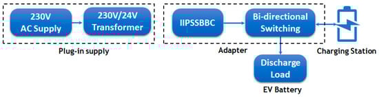
Figure 1.
Block diagram of proposed system.
The proposed converter, namely, IIPSSBBC, is modeled using diodes (D1, D2, D3, D4, D5, D6, D7, D8, DA, and DB), inductors (L1, L2, L3, and L4), switches (SW1 and SW2), and a parallel capacitor (C). A pictorial representation of the recommended converter model is given in Figure 2.
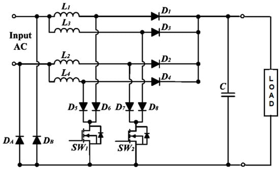
Figure 2.
Diagram of proposed circuit.
During the first half cycle (positive) of the input voltage, inductor L1 stores energy through diode D6 and switch SW1, as revealed in Figure 3a. Similarly, inductor L2 stores energy through diode D8 and switch SW2. In the same way, during the second half cycle (negative) of the input voltage, inductors L2 and L4 store energy through diodes D5 and D7 and switches SW1 and SW2, as shown in Figure 3b. The positive half cycle is divided into four modes. The modes of operation are explained in detail below.
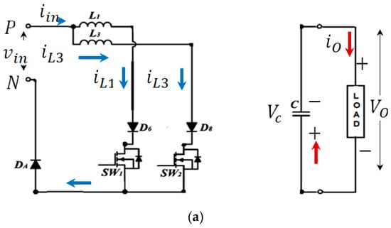
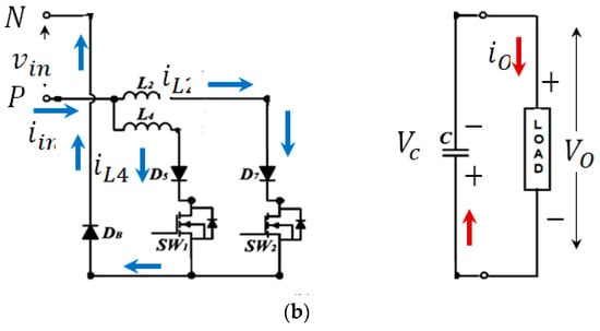
Figure 3.
Operations of the converter: (a) positive half-cycle and (b) negative half cycle.
- Mode 1: (t0–t1)
During this mode, switches SW1 (switch 1) and SW2 (switch 2) are in the ON condition. Therefore, the inductor stores energy through diodes D6 (diode 6) and D8 (diode 8) and switches SW1 and SW2. Capacitor C discharges the energy to the load, as presented in Figure 4a. The currents enter through L1 (inductor 1) and L3 (inductor 3) are the same, where the change in current () is given as follows:
where denotes the input voltage (V). represents the duty cycle.
symbolizes the switching time (s). and represent the switches. to represent the inductors. to represent the diodes. represents the change in the current (A).
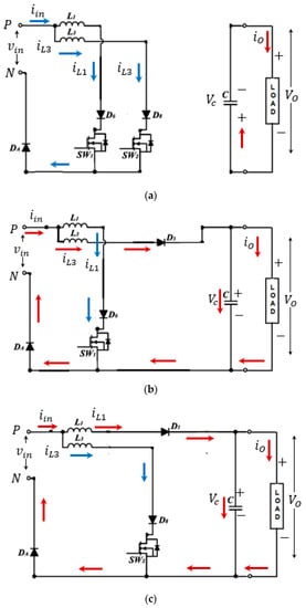
Figure 4.
Different modes of operation: (a) modes 1 and 3, (b) mode 2, and (c) mode 4.
- Mode 2: (t1–t2)
During this mode, SW1 is ON, and SW2 is OFF. The current that passes via inductor L1 increases linearly and stores energy through D6 and SW1, as shown in Figure 4b, where the change in the current is given as follows:
- Mode 3: (t2–t3)
During this mode, switches SW1 and SW2 are in the ON position. Similar to mode 1, inductors L1 and L3 store energy, and capacitor C discharges the energy to the load, as illustrated in Figure 4a.
- Mode 4: (t3–t4)
During this mode, switch SW1 is OFF, and SW2 is ON; the current flow is depicted in Figure 4c. Inductor L3 stores energy through diode D8 and switch SW2. However, inductor L1 releases the energy to the load through D1 (diode 1). The change in the current of L3 is derived as follows:
where the term represents the output voltage.
Further, the waveforms of the various components of the proposed converter, namely, the gating signals, inductor current, FET current, boost diode current, and body diode current, are illustrated in Figure 5.
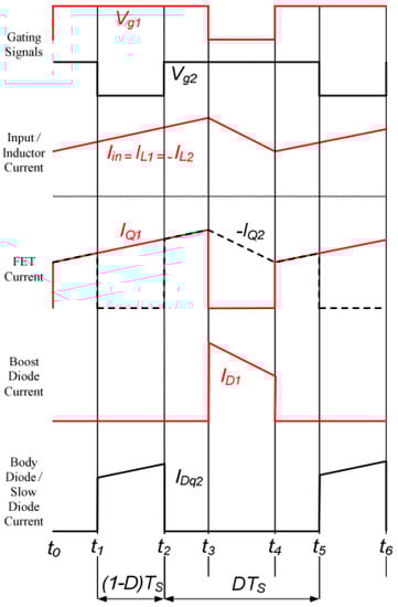
Figure 5.
The waveforms of the suggested converter.
4. Results and Discussion
The proposed converter is modeled in MATLAB 2021 with the IIPSSBBC in addition to the bi-directional converter in order to speed up the charging time. Hence, it is expected that the converter is more convenient and provides charging in a fast time. The complete model is developed using the Simulink platform, and it is given in Figure 6. The comprehensive simulation parameters of the proposed design are illustrated in Table 1.
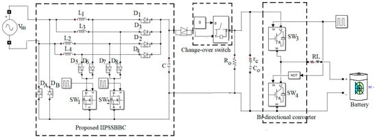
Figure 6.
Simulation illustration of proposed system.

Table 1.
Simulation parameters.
Further, the characteristic features of a lithium-ion battery are simulated by a nominal discharge current of 0.4347C (21.73A), and they are depicted in Figure 7. The lithium-ion battery shows healthier behavior against the rated current at a designated temperature. Then, the complete system is simulated in MATLAB 2021 as per the data given in Table 1.
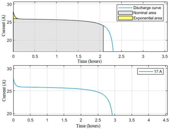
Figure 7.
Nominal current discharge of the battery.
As shown in the simulation model, the input power is connected to an interleaved SEPIC converter, and Figure 8 displays the simulated outcomes of the AC source applied to the proposed converter model. The model shows a voltage rating of 24 V and a current magnitude of 16 A.
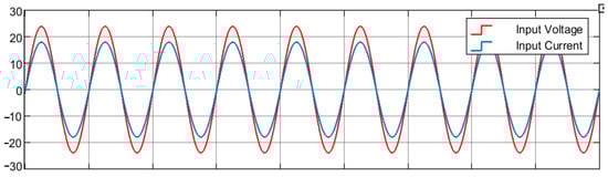
Figure 8.
AC source fed to the converter.
The proposed converter has MOSFET switches, and it allows the voltage to decrease during the switching sequence. The MOSFET switches have a voltage stress of 30 V during the conduction. Figure 9 shows the MOSFET parameters, namely, the voltage in MOSFET 1 and the voltage in MOSFET 2 and the gate pulse.
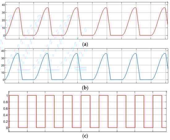
Figure 9.
MOSFET parameters: (a) voltage in MOSFET 1 and (b) voltage in MOSFET 2 and (c) gate pulse.
The load is linked to operate the battery for discharging. Moreover, the charging of the battery is carried out based on the switching sequence. A load of 200 W is coupled to the battery output. Figure 8 displays the various electrical parameters across the battery and the load. The state of charge (SoC) of the battery is maintained at about 44.925%, as illustrated in Figure 10a. The battery current is observed to be of a greater magnitude, at about 280 A, with a battery voltage value of 26 V. The battery power displays a wattage of 5000 W, and the same energy is taken by the load from the battery, as described in Figure 10d. Notably, healthier behavior can be observed in the power deliverance to the load and the temperature characteristics described in Figure 11.
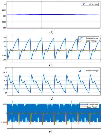
Figure 10.
Load parameters: (a) SoC, (b) battery and load current, (c) battery voltage, and (d) battery power.
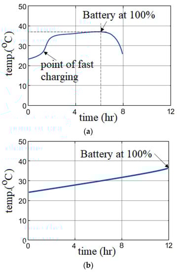
Figure 11.
Temperature characteristics of battery: (a) proposed system and (b) conventional system.
Further, the temperature characteristic of the proposed system during the fast-charging process of the battery is assessed and depicted in Figure 11a. It is found that there is a sudden increase in temperature after 2 h of charging, but flat characteristics are maintained for successive hours of charging, and a temperature value of 38 °C is not exceeded. To determine the effectiveness of the proposed system, the conventional charging process of the battery is evaluated, and this is illustrated in Figure 11b. It is found that there is a linear increase in temperature up to 12 h of charging and that the maximum value is about 36 °C.
Moreover, an attempt is made to develop a hardware model of the proposed converter, as shown in the above illustration. A block diagram of the anticipated prototype model is given in Figure 12. The prototype model consists of an input supply stepped down to 6V. The Alternating Current output acts as an input to the interleaved phase-shifted semi-bridgeless converter. The output of the converter is given to the lithium-ion battery as shown below figure.
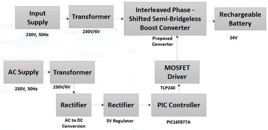
Figure 12.
Block diagram of hardware prototype.
In the block diagram, the circuit is designed as a prototype model, and a complete description of the circuit is given in Figure 13.
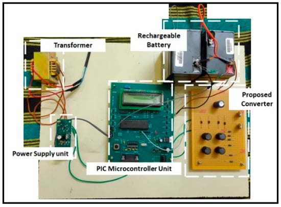
Figure 13.
Hardware prototype model.
The hardware consists of an AC source and it is converted into DC using a rectifier panel. The input is directly given to the proposed transformer with a DC/DC converter comprising a high gain. The MOSFET driver circuit is designed and controlled using a PIC16F877a microcontroller. The PIC controller is powered using the transformer stepped down from 230 V to 6 V and later rectified. The regulator IC LM7805 is used to provide the regulated output. The hardware input and the output are measured using a multimeter and CRO. Figure 14 shows the detailed results measured during the hardware operation. Specifically, Figure 14a displays the input and output voltages of about 6 V and 18 V, respectively. The gate pulse magnitude is observed from the controller of the hardware, and it is found to be 15.2 V. The voltage at the load is observed using CRO, and it is given in Figure 14e.
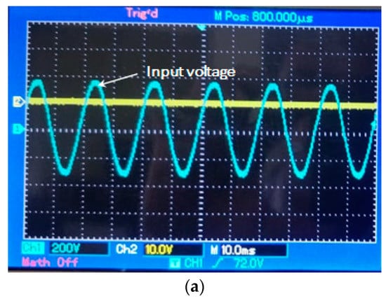
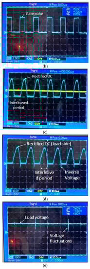
Figure 14.
Hardware results: (a) input voltage, (b) gate pulse of proposed converter, (c) rectified Direct Current (DC) voltage on the charging side, (d) rectified voltage on discharging side, and (e) voltage at load terminals.
Further, it is essential to compare the conventional interleaved phase-shifted semi-bridgeless boost converter and the modified interleaved phase-shifted semi-bridgeless boost converter in order to assess the usefulness of the projected model. It is detected that the charging current of the conventional converter model is 8 A, but the improved converter model attained a current magnitude of 16 A. Similarly, for the 50 Ah battery modules, the charging time of the battery is found to be 12.5 h for the conventional converter model and 6 h for the proposed improved model.
Based on the observed results, the proposed converter shows superior performance for electric vehicle battery applications, and this is verified using simulated and prototype hardware setups. However, a large-scale hardware design is required to warrant the effectiveness of the proposed converter, and that can be the focus of future works.
5. Conclusions
Mathematical modeling in MATLAB/Simulink is carried out for battery charging stations. Simulation work is carried out for modified interleaved phase-shifted semi-bridgeless boost converter (IIPSSBBC) systems. From the observed results, the battery charging current in the conventional system is 8 A but the battery charging current in the proposed IIPSSBBC is 16.5 A which is twice the value compare with conventional one. It is also noted that, for a 50 Ah battery and a discharge load capacity of 5000 W, the charging time is 12.5 hrs in the conventional method and 6 hrs in the recommended system. This is achieved by operating the proposed converter under ZVS and ZCS conditions. Based on the simulation work, a prototype model of a similar system is developed. The prototype model is investigated for a low power rating considering the cost of the project. The prototype design is stepped down from 230 V to 6 V and is given to the suggested converter. The converter increases the voltage from 6 V to 12 V and charges the battery. The proposed model can be developed for the large-scale fast charging of electric vehicles.
Author Contributions
Conceptualization, K.K. and R.K.; methodology, K.K.; software, K.K.; validation, R.K. and M.H.A.; formal analysis, M.H.A.; investigation, K.K.; resources, R.K.; writing—original draft preparation, K.K.; writing—review and editing, R.K., Z.W.G. and M.H.A.; visualization, K.K.; supervision, M.H.A. and Z.W.G.; project administration, R.K. All authors have read and agreed to the published version of the manuscript.
Funding
This research received no external funding.
Institutional Review Board Statement
Not applicable.
Informed Consent Statement
Not applicable.
Data Availability Statement
The data presented in this study are available on request from the corresponding author. The data are not publicly available due to internal institutional policies.
Conflicts of Interest
The authors declare no conflict of interest.
References
- Badawy, M.O.; Sharma, M.; Hernandez, C.; Elrayyah, A.; Guerra, S.; Coe, J. Model Predictive Control for Multi-Port Modular Multilevel Converters in Electric Vehicles Enabling HESDs. IEEE Trans. Energy Convers. 2022, 37, 10–23. [Google Scholar] [CrossRef]
- The International Organization of Motor Vehicle Manufacturers. World Motor Vehicle Production by Country and Type. Available online: http://www.oica.net/wp-content/uploads/total-2013-2.pdf (accessed on 4 September 2014).
- Hariri, R.; Sebaaly, F.; Kanaan, H.Y. A Review on Modular Multilevel Converters in Electric Vehicles. In Proceedings of the IECON 2020 the 46th Annual Conference of the IEEE Industrial Electronics Society, Singapore, 18–21 October 2020. [Google Scholar] [CrossRef]
- Quraan, M.; Yeo, T.; Tricoli, P. Design and Control of Modular Multilevel Converters for Battery Electric Vehicles. IEEE Trans. Power Electron. 2016, 31, 507–517. [Google Scholar] [CrossRef]
- Zhou, W.; Cleaver, C.J.; Dunant, C.F.; Allwood, J.M.; Lin, J. Cost, range anxiety and future electricity supply: A review of how today’s technology trends may influence the future uptake of BEVs. Renew. Sustain. Energy Rev. 2023, 173, 113074. [Google Scholar] [CrossRef]
- Akhormeh, A.R.N.; Abbaszadeh, K.; Moradzadeh, M.; Shahirinia, A. High-Gain Bidirectional Quadratic DC–DC Converter Based on Coupled Inductor With Current Ripple Reduction Capability. IEEE Trans. Ind. Electron. 2021, 68, 7826–7837. [Google Scholar] [CrossRef]
- Harasimczuk, M. A QR-ZCS boost converter with tapped inductor and active edge-resonant cell. IEEE Trans. Power Electron. 2020, 35, 13085–13095. [Google Scholar] [CrossRef]
- Venkatesan, C.; Kannadasan, R.; Ravikumar, D.; Loganathan, V.; Alsharif, M.H.; Choi, D.; Hong, J.; Geem, Z.W. Re-Allocation of Distributed Generations Using Available Renewable Potential Based Multi-Criterion-Multi-Objective Hybrid Technique. Sustainability 2021, 13, 13709. [Google Scholar] [CrossRef]
- Balaguru, V.S.S.; Swaroopan, N.J.; Raju, K.; Alsharif, M.H.; Kim, M.-K. Techno-Economic Investigation of Wind Energy Potential in Selected Sites with Uncertainty Factors. Sustainability 2021, 13, 2182. [Google Scholar] [CrossRef]
- Raju, K.; Elavarasan, R.M.; Mihet-Popa, L. An Assessment of Onshore and Offshore Wind Energy Potential in India Using Moth Flame Optimization. Energies 2020, 13, 3063. [Google Scholar]
- Subramanian, S.; Sankaralingam, C.; Elavarasan, R.M.; Vijayaraghavan, R.R.; Raju, K.; Mihet-Popa, L. An Evaluation on Wind Energy Potential Using Multi-Objective Optimization-Based Non-Dominated Sorting Genetic Algorithm III. Sustainability 2021, 13, 410. [Google Scholar] [CrossRef]
- Ahmed, A.; Khan, M.A.; Badawy, M.; Sozer, Y.; Husain, I. Performance analysis of bi-directional DC-DC converters for electric vehicles and charging infrastructure. In Proceedings of the IEEE Energy Conversion Congress and Exposition, Denver, CO, USA, 15–19 September 2013. [Google Scholar] [CrossRef]
- Murshid, S.; Singh, B. Reduced Sensor Based PMSM Driven Autonomous Solar Water Pumping System. IEEE Trans. Sustain. Energy 2020, 11, 1323–1331. [Google Scholar] [CrossRef]
- Dixit, A.; Pande, K.; Gangavarapu, S.; Rathore, A.K. DCM-Based Bridgeless PFC Converter for EV Charging Application. IEEE J. Emerg. Sel. Top. Ind. Electron. 2020, 1, 57–66. [Google Scholar] [CrossRef]
- Pandey, R.; Singh, B. Canonical Switching Cell (CSC) Converter-Based Power Factor-Corrected Battery Charger for E-Rickshaw. IEEE Trans. Ind. Appl. 2020, 56, 5046–5055. [Google Scholar] [CrossRef]
- Kanimozhi, G.; Natrayan, L.; Angalaeswari, S.; Paramasivam, P. An Effective Charger for Plug-In Hybrid Electric Vehicles (PHEV) with an Enhanced PFC Rectifier and ZVS-ZCS DC/DC High-Frequency Converter. J. Adv. Transp. 2022, 2022, 7840102. [Google Scholar] [CrossRef]
- Ortiz-Castrillón, J.R.; Mejía-Ruiz, G.E.; Muñoz-Galeano, N.; López-Lezama, J.M.; Cano-Quintero, J.B. A Sliding Surface for Controlling a Semi-Bridgeless Boost Converter with Power Factor Correction and Adaptive Hysteresis Band. Appl. Sci. 2021, 11, 1873. [Google Scholar] [CrossRef]
- Chen, Z.; Liu, B.; Yang, Y.; Davari, P.; Wang, H. Bridgeless PFC Topology Simplification and Design for Performance Benchmarking. IEEE Trans. Power Electron. 2021, 36, 5398–5414. [Google Scholar] [CrossRef]
- Lopez-Santos, O.; Cabeza-Cabeza, A.; Garcia, G.; Martinez-Salamero, L. Sliding Mode Control of the Isolated Bridgeless SEPIC High Power Factor Rectifier Interfacing an AC Source with a LVDC Distribution Bus. Energies 2019, 12, 3463. [Google Scholar] [CrossRef]
- Fan, M.; Shi, L.; Yin, Z.; Jiang, L.; Zhang, F. Improved Pulse Density Modulation for Semi-bridgeless Active Rectifier in Inductive Power Transfer System. IEEE Trans. Power Electron. 2019, 34, 5893–5902. [Google Scholar] [CrossRef]
- Kanimozhi, G.; Sreedevi, V.T. Semibridgeless Interleaved PFC Boost Rectifier for PHEV Battery Chargers. IETE J. Res. 2018, 65, 128–138. [Google Scholar] [CrossRef]
- Khalid, M.R.; Alam, M.S.; Amrr, S.M.; Jamil Asghar, M.S. Multi-Pulse Converter based Rectification Scheme for Improving Power-Quality of EVs Charging Station. In Proceedings of the International Conference on Sustainable Energy and Future Electric Transportation (SEFET), Hyderabad, India, 21–23 January 2021. [Google Scholar] [CrossRef]
- Mohammadi, F.; Nazri, G.A.; Saif, M. A Bidirectional Power Charging Control Strategy for Plug-in Hybrid Electric Vehicles. Sustainability 2019, 11, 4317. [Google Scholar] [CrossRef]
- Rameshkumar, T.; Chandrasekar, P.; Kannadasan, R.; Thiyagarajan, V.; Alsharif, M.H.; Kim, J.H. Electrical and Mechanical Characteristics Assessment of Wind Turbine System Employing Acoustic Sensors and Matrix Converter. Sustainability 2022, 14, 4404. [Google Scholar] [CrossRef]
- Rajalakshmi, M.; Chandramohan, S.; Kannadasan, R.; Alsharif, M.H.; Kim, M.-K.; Nebhen, J. Design and Validation of BAT Algorithm Based Photovoltaic System Using Simplified High Gain Quasi Boost Inverter. Energies 2021, 14, 1086. [Google Scholar] [CrossRef]
Disclaimer/Publisher’s Note: The statements, opinions and data contained in all publications are solely those of the individual author(s) and contributor(s) and not of MDPI and/or the editor(s). MDPI and/or the editor(s) disclaim responsibility for any injury to people or property resulting from any ideas, methods, instructions or products referred to in the content. |
© 2023 by the authors. Licensee MDPI, Basel, Switzerland. This article is an open access article distributed under the terms and conditions of the Creative Commons Attribution (CC BY) license (https://creativecommons.org/licenses/by/4.0/).