Article

Orthogonal Experimental Study on Remediation of Ethylbenzene Contaminated Soil by SVE

1
School of Resources and Safety Engineering, Central South University, Changsha 410083, China
2
School of Resources and Geosciences, China University of Mining and Technology, Xuzhou 221000, China
3
Department of Civil Engineering, Monash University, Melbourne, VIC 3800, Australia
*
Author to whom correspondence should be addressed.
Sustainability 2023, 15(2), 1168; https://doi.org/10.3390/su15021168
Submission received: 22 November 2022 / Revised: 2 January 2023 / Accepted: 4 January 2023 / Published: 8 January 2023

Abstract

:
Soil vapor extraction (SVE) technology has strong potential value in the decontamination of soils dominated by volatile contaminants. In this paper, in order to evaluate in detail the influence of the main factors on the efficiency of SVE, L9(34) orthogonal tests and response surface analysis were carried out using a self-developed one-dimensional SVE system model. A first-order kinetic reaction model was also employed to analyze the relationship between pollutant concentration and time. The thermal reaction unit of SVE technology with a scale consistent with the soil column of the indoor test was simulated using COMSOL simulation software. The obtained results indicate that the most important factors affecting the performance of SVE are time, temperature, and contaminant concentration, while the influence of the extraction flow rate is not significant. A first-order kinetic reaction model can be used to predict the half-life of contaminant concentrations. Combined with the desirability function, the optimal conditions for the removal of ethylbenzene from soil were: time 180 min, temperature 20 °C, extraction flow 6000 mL/min, and contaminant concentration 2%. The developed numerical model, 3D-SVE, nicely simulates laboratory findings. These results can provide ideas to improve the efficiency of SVE.

1. Introduction

At present, soil environmental issues are becoming more and more serious in the world, especially in developing countries [1]. The general public has also become worried about acute and chronic toxic threats to health and the environment, about loss of natural resources, and adverse effects on the value of their homes [2]. Petroleum and petrochemical products often contaminate soil in the form of non-aqueous-phase liquids (NAPL) [3]. The most common hydrocarbon soil remediation methods include in situ thermal desorption techniques, ex situ thermal desorption techniques, bioremediation, and soil vapor extraction (SVE) [4]. Among them, SVE is an in situ remediation technology recommended by the US federal Superfund program for its efficiency and economy [5]. This technology is mainly used to clean up the volatile and semi-volatile contaminants in soil.
The efficiency of SVE technology for the remediation of contaminated soil is influenced by many factors, including operating conditions (such as soil temperature and extraction flow), contaminant properties (such as vapor pressure and solubility), and soil characteristics (such as natural porosity, permeability, organic matter or water contents) [1,6,7,8]. The increase in vapor extraction flow leads to a higher contaminant-removal efficiency. Furthermore, an optimal vapor extraction flow for the contaminant can be acquired through calculation [9]. Temperature is one of the most important factors in the performance of SVE. Field studies have reported that various thermally enhanced SVE applications (radio frequency heating, electrical resistance heating, hot air injection, steam injection) elevate temperatures and vapor pressures to different levels to enhance efficiency [10,11]. The applications of T-SVE (thermally enhanced soil vapor extraction) have largely improved the removal efficiency of pollutants, expanded the extent of pollutants, and decreased the remediation time [12]. It has also been reported that soil grain sizes, operation period, contaminant concentration, and organic content have a great impact on removal efficiency [13,14]. Shi et al. [7] found that the removal rate of contaminants was proportional to the extraction time, until the removal rate reached saturation, by a layered extraction test. Qin et al. [9] investigated the factors influencing the removal of chlorobenzenes from unsaturated soils by SVE and indicated that the higher the organic matter content in the soil, the lower the removal efficiency through a series of one-dimensional column experiments.
Existing studies on the remediation of hydrocarbon-contaminated soils mainly focus on the comparison of influencing factors, and few studies on adsorption kinetics have been carried out in conjunction with parameter-optimization systems. Yang et al. [4] used the Freundlich equation to fit the adsorption process, calculated the kinetic parameters, and investigated the applicable range of adsorption kinetics. In addition, Yu et al. [8] demonstrated by T-SVE experiments that the organic matter removal process in petroleum hydrocarbon soils also conforms to the Elovich thermal desorption kinetic equation. Yang et al. [15] studied the adsorption/desorption behavior and kinetics of the volatile organic pollutant toluene in soils with different pores, and the results showed that the first-order model is more suitable to describe the adsorption process, implying that physical adsorption plays a major role.
At present, most of the studies on SVE are stuck in indoor experiments and field trials [16]. Ding et al. [6] designed a thermal oxidation SVE (TOSVE) system and conducted laboratory simulations. The innovative addition of natural-material slag and an oxidant to the tail gas treatment device improved the tail gas treatment efficiency. Shi et al. [7] constructed a soil vapor extraction to remove benzene-contaminated soil in a layered extraction simulator, and layered intermittent extraction could remove more than 90% of benzene from the soil. Yang et al. [5] investigated BTEX migration and SVE remediation in a sandbox laboratory and demonstrated that SVE removal of benzene was the highest among the four tested contaminants under low-temperature conditions. Labianca et al. [14] examined the performance of SVE remediation systems for petroleum hydrocarbon contaminated sites, with a total final efficiency equal to 73%.
Numerical modeling has become an important tool in the development of SVE technology by providing a better understanding of the SVE processes and enhancement of SVE applications [17,18]. Van Thinh Nguyen et al. [17] developed a 3D-SVE model based on the COMSOL finite element method, which simulated well the laboratory findings and allowed to vary the important control mass transfer relations. D. Esrael et al. [19] proposed a model to simulate the SVE/exhaust process focusing on the effect of mass transfer coefficient evaluation on the simulation of experimental results and COMSOL was used as a numerical method to solve the 2D axisymmetric model. Xu et al. [20] used the coupling technique of ERH (electrical resistance heating) and SVE to optimize the electrode arrangement by simulating the site temperature distribution patterns under different physical fields using COMSOL with soil temperature as a probe. Yang et al. [21] derived the applicability of SVE technology at low temperatures and the mechanism of benzene removal based on the TMVOC model. Numerical simulations can be used to help researchers design and evaluate SVE systems.
Currently, the main method to study the factors influencing SVE is the control variable method [9]. However, these factors interact and constrain each other in actual SVE operations [22,23,24]. To evaluate the interactive effects of operating parameters on SVE performance, this paper designed a novel SVE thermal reaction unit with ethylbenzene as the target pollutant, and for the first time used a combination of orthogonal tests and response surface analysis, and obtained the highest pollutant removal rates. The kinetic characteristics of pollutant removal during SVE operation were verified with a first-order kinetic fitting model. The best combination was also simulated by 3D numerical simulation to obtain the contaminant migration pattern and verify the experimental results.

2. Materials and Methods

2.1. Contaminated Soil Collection and Determination

The silt was collected from an uncontaminated sinkhole in Yunlong District, Xuzhou. Figure 1 shows the location of the sampling point. The depth of the collapse pit is about 4 m, the area is about 25 m2. The fresh soil samples were tested and no petroleum hydrocarbon was found in the soil. The silty soil samples were pulverized and sieved to pass 200 mesh. Soil texture and organic matter content were determined using the hydrometer method and potassium dichromate oxidation spectrophotometric method, respectively. The specific surface area and micropore volume of soil were analyzed by N2-BET analysis using a Quantachrome NOVA 4200e analyzer. Table 1 shows the basic physical and chemical properties of soil samples. All soil samples were dehydrated at 200 °C for 8 h.

2.2. Specimen Preparation and Processing

Ethylbenzene (purity = 98.5%) was selected as the target pollutant and blended homogeneously with silty soil. Subsequently, each group of soil samples was placed in a sealed bag and stored in a refrigerator at 4 °C for 5 days so that the ethylbenzene in the soil was evenly distributed. The volume of ethylbenzene required for each group of soil columns can be calculated using Equation (1).
V = 6505 ∗ q/0.867 ∗ 0.985
where V is the volume of ethylbenzene and q is the percentage of ethylbenzene in the soil sample. The soil mass of each group is 6505 g, and the relative density of ethylbenzene is 0.867 (25/4 °C). Each group of test soil columns was sealed immediately after assembly, then put into the test temperature box, and kept at the set temperature for three hours to ensure that the temperature of the whole system reached the set temperature. Subsequently, the glass rotameter was adjusted to the set value, the SVE device started, and the time recorded. The experimental time of each experimental group was divided into 8 segments, and 8 soil samples were collected with the disposable probe in each group. Soil samples were sealed in disposable brown glass vials and then frozen in the refrigerator, awaiting analysis. The volume of each soil sample was about 20 mL.

2.3. Target Pollutant Detection

The gas chromatograph (GC) quantitative analysis detector was a hydrogen flame detector (FID). The carrier gas used high-purity argon, and the chromatographic column was an SH-Rtx-1 capillary column. The column temperature was increased from 40 °C to 300 °C at a rate of 15 °C/min and maintained at this temperature for five minutes. The inlet temperature was 250 °C, and the temperature of the detector was 320 °C. Liquid injection and external standard methods were used for the quantitative analysis of curve calibration.

2.4. SVE Experimental Model

In this study, an experimental model which was able to meet the experimental conditions was constructed and tested at an indoor site at China University of Mining and Technology. An overview of the setup of SVE is given in Figure 2. The model was made of tempered glass with a thickness of 12 mm; the useful diameter and height of the model were 250 and 800 mm, respectively; the inlet was equipped with an activated carbon filter and the top of the glass column was sealed with PTEF material. There was a fixed sampling port during the test. The ethylbenzene in the extraction gas was first liquefied and recovered by a condenser, and then absorbed by ethanol. The designed glass clay column was used as the reaction unit of SVE technology, the pump was the power unit, and the powdered activated carbon condenser tube was installed as the recovery unit. The negative pressure power provided by the pump drives the gas flow inside the soil so that the contaminants are carried out of the soil by the airflow. At the same time, as some of the volatilized pollutants are separated from the soil, most of the pollutants occupying the non-aqueous phase of the soil will appear to be further volatilized under the action of their own saturated vapor pressure to cause the gas-liquid system pressure to reach equilibrium. Experiments and related theories have shown that the bottom-pumping approach produces better directional air pressure than top pumping, inflation, or bottom inflation in terms of the dynamics [25].

2.5. Kinetic Analysis

Adsorption kinetics provide valuable information about the mechanism of adsorption [26]. The Freundlich kinetic equation was used to analyze the process of a series of reaction mechanisms, mainly for describing the exponential decay of adsorption energy with increasing surface saturation [4]. There are many applications of the first-order kinetic reaction mathematical model, such as pollutant degradation, radioactive decay, and heating [27,28]. In this paper, we investigated whether the experimental reaction process conforms to the first-order kinetic reaction model. The mathematical model of the reaction is as follows:
dC/dt = −kt,
lnC = lnC0kt,
T1/2 = 0.693/k,
where t is time, C is the concentration of pollutant, C0 is the initial concentration, k is the reaction rate constant, and k > 0 and does not change with the concentration of reactants. Equation (3) is a special solution of Equation (2) when t0 is equal to 0. The first-order constant k is the slope of the natural logarithm of the contaminant concentration against time t and is commonly estimated by the best-fit linear regression line of the ordinary least squares. T1/2 is the half-life of the contaminant concentration in the system, and it can be calculated by Equation (4) [29].

2.6. Orthogonal Experiments

The orthogonal testing method is a design method for investigating multiple factors and levels [30]. It is conducted by selecting an appropriate number of representative test cases from a large number of test data, which are uniformly dispersed and neatly comparable [31]. This paper aims to elevate the remediation efficiency and reduce costs by investigating the operating parameters of SVE. In this orthogonal test design, the removal rate was chosen as the indicator. The following four parameters were investigated: time, temperature, extraction flow, and contaminant concentration. In the remainder of the article, those parameters are indicated as A, B, C, and D, respectively. Three levels are considered in the work for each factor, that is, the L 9 ( 3 4 ) orthogonal array, which is illustrated in Table 2.
As can be seen in Table 3, the numbers are listed from 1 to 9 in the first column, representing the 9 tests. The second to fourth columns represent the levels of the different factors A, B, C, and D. Each row in the table corresponds to a test, in which the numbers 1, 2, and 3 represent different levels of each factor as shown in Table 2. From the orthogonal array designed above, it can be observed that, for any column, all three levels are involved and occur with equal frequency. Between any two columns, there are all possible combinations of different levels of occurrence, with an equal number of occurrences. Finally, given that our survey involved only four factors, and the last column is not empty, four repeated experiments should be designated for the error evaluation and variance analysis.

2.7. Setting up the 3D-SVE Model

The porous medium of the model is soil, not idealized sandy soil. The soil itself is subject to cohesion, as well as negative and positive pressures. The negative pressure comes from the pumping borehole, while the positive pressure comes from the various stresses in the soil itself. The pumping borehole causes a rapid flow of contaminants within the soil, which requires consideration of gravity, pressure, viscous resistance, and permeability resistance. The physics interface of free and porous media flow in COMSOL was selected under comprehensive consideration, which describes free flow and fast flow in porous media, and the corresponding control equations are shown in Equation (5). The contaminant material filled in the pores of the porous media is ethylbenzene with fluid properties. The values of the relevant parameters set in the model are shown in Table 4, and the outlet pressure is set to −101.325 kPa [32,33].
ρ u t   =     ×   [ p I   +   κ ]   +   F   +   ρ g ,
ρ∇ × u = 0,
κ = μ(∇u + (∇u)T),
where ρ is the fluid density, u is the fluid velocity, p is the fluid pressure, I is the unit matrix, κ is the permeability, F is the fluid resistance, and μ is the dynamic viscosity.

3. Results and Discussion

3.1. Kinetic Characteristics of Pollutant Removal in SVE

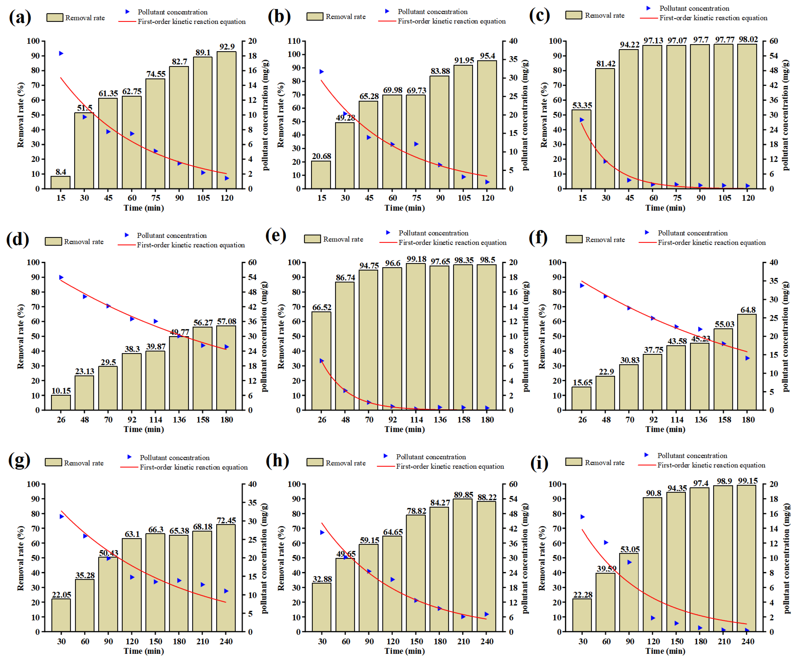
The removal rate of ethylbenzene in nine groups of experiments is shown in Figure 3a–i. As can be observed from Figure 3, the removal rate increases with time in each group of experiments. Except for test 1 and test 2, there are obvious tailing effects in other groups of tests, which causes a decrease in treatment efficiency [34]. This is because there is free energy on the surface of fine-grained soil, and hydrocarbon components can be adsorbed by its surface [4]. These show that the fabrication and installation of the experimental device conform to the model design, and the operation state of the device is stable.
The scatter plot of pollutant concentration with time can be seen in Figure 3a–i. Obviously, the pollutant concentration decreases with time in nine tests. As shown in Figure 3, the first-order kinetic reaction model (Equations (2)–(4)) is also employed to fit the change in pollutant concentration with time. In Table 5, the minimum value of R2 is greater than 0.92, which indicates that the experimental reaction process can be described by the first-order kinetic model [35]. Based on the reaction model, the half-life of pollutant concentration in each test was calculated, the results are shown in Figure 4.
The cumulative bar graph of the half-life for nine tests is shown in Figure 4. It can be observed that the percentage of half-life time in tests 4 and 5 (180 min) is the smallest, but test 4 has the lowest removal rate. The percentage of half-life time in test 3 (120 min) is 10%, while half-life time is the shortest (12.77 min), which shows that the performance of test 3 and test 5 is much better than that of other groups.

3.2. Range Analysis

Table 6 shows the scheme adopting the L9(34) orthogonal design to study the operating parameters of the SVE. Each row represents a test and a specific combination of levels for each factor. Therefore, good tests are investigated with the assistance of model experiments. The right column of the table shows the results of the indicators (I–IV) for each repeated test, i.e., the removal rate for each test. The results of the indicators are presented in the right column of the table.
In this paper, range analysis was employed to examine the results of orthogonal tests. The results of the range analysis are presented in Table 7. First, the sum of the removal rate Kij and the average values K ij for level j under factor i (i = 1,2,3,4; j = 1,2,3) were computed. When determining the i-th factor, the difference between these means reflects the effect of the level of the i-th factor on the removal rate. Following this, we obtained the range Ri by Equation (8):
Ri = max(Ki1, Ki2, Ki3)min(Ki1, Ki2, Ki3),
where Ri represents the influence degree of the factor.
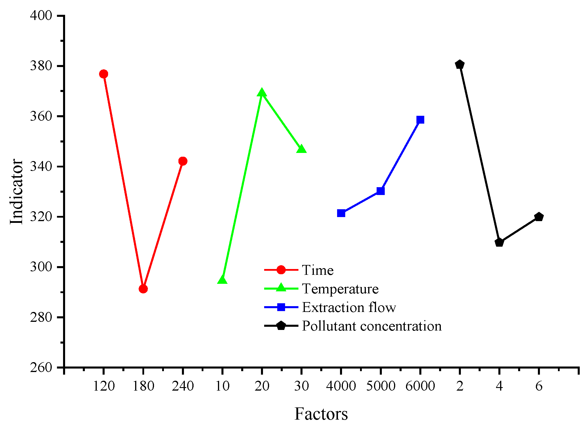
From Table 7, it can be observed that the most influential factor in SVE performance is time, followed by temperature and contaminant concentration. The impact of extraction flow is minimal. Qin et al. [9] showed that the increase in removal rate was not significant at higher extraction flow levels. Figure 5 is plotted and the indicators for each factor can be characterized by the removal rate. It is clear from the figure that the highest points of the four broken lines indicate the maximum average removal rate for each level of the factor. In principle, a specific optimal solution needs to be determined, and in general, it is desirable to choose from the experiments performed. If the required index is large, it is better to choose the level that can make the index large enough to meet the experimental purpose; if the required index is small, it is better to choose the level that can make the index small enough to meet the experimental purpose. Finally, it is also necessary to consider whether the scheme can improve experimental efficiency and reduce experimental costs.
In this experiment, the maximum value of the removal rate index is sought according to the requirements. Combined with Figure 5 above, the optimal solution is time: 120 min, temperature: 20 °C, extraction flow: 6000 mL/min, and contaminant concentration: 2%. It can be known that if this scheme is not in the experimental scheme as originally designed, then it is necessary to compare this scheme with the best experimental scheme with the best index in the original orthogonal experimental design table. The results of the comprehensive analysis are integrated as shown in Table 6, and it is easy to know that test 5 has the best comprehensive index. In Table 7, the average value of indicators of test 3 is slightly higher than that of test 5; however, in the four replicate experiments, the indicators of test 5 are higher than those of test 3 in all three replicate experiments. Moreover, the removal rate of test 5 in the fourth replicate experiment is too low, that is, lower than 4% compared with the previous three replicate experiments, so the results of the fourth replicate experiment can be judged as the error term. In conclusion, test 5 was selected as the experimental group with the best overall index.
A validation experiment is needed for the optimal solution, and only the time factor differs between this optimal solution and the factors of test 5. In the previous analysis, in the mathematical model of the first-order kinetic reaction equation it could be verified that the pollutant ethylbenzene concentration changes throughout the experimental process. The model function is a decreasing function of time and the overall fit assessment meets the criteria. Therefore, it can be concluded that the removal rate at 120 min will not be higher than the removal rate at 180 min. Taken together, the optimal combination of the factors in this orthogonal experiment was A2B2C3D1.

3.3. Variance Analysis

The results of the above analysis are based on the range analysis method, but range analysis cannot identify data fluctuations due to changes in test conditions and test errors, nor can it provide an accurate quantitative analysis of the significance of each factor [31]. Compared with the range analysis, the judgment accuracy of ANOVA is relatively higher [36]. Therefore, we need to verify the reliability of the conclusion through variance analysis [37]. The computational procedure of ANOVA can be described in Equations (9)–(14).
SST = SSfactors + SSerror,
dfT = dffactors + dferror,
S S T = l = 1 n m = 1 r x lm 2 T 2 n r
dfT = nr − 1,
S S factor = 1 a r i = 1 a j = 1 b K i j 2 T 2 n r ,
dffactor = b − 1,
where SST represents the sum of squares, SSerror represents the sum of errors, and SSfactors represents the sum of squares for regression. In Equation (10), dfT means the total degrees of freedom (DF), dffactor is the DF of one factor, dferror represents the DF of error. In Equation (11) n(n = 9) is the number of tests required for the orthogonal array, r(r = 4) is the number of replicate experiments, xlm is the indicator value for test l under repeat m (l = 1, 2, 3, 4, 5, 6, 7, 8, 9; m = 1, 2, 3, 4). T represents the sum of nine test indicators (including repeated experiments).
Following this, the mean square of each factor (MSfactor), the mean square of error (MSerror), and the F-value of each factor (Ffactor) can be calculated according to the following Equations (15)–(17).
MS factor = S S f a c t o r d f f a c t o r
MS error = S S e r r o r d f e r r o r
F factor = M S f a c t o r M S e r r o r r
The critical value of F (Fcritical) is a function of DF and significance level (α). If Ffactor > Fcritical, it can be considered that this factor has a significant impact on the test results. To simplify the discussion, only the calculated results of the experimental data are listed in Table 8.
From Table 8, it can be noted that the FA, FB, FC, and FD exceed the Fcritical(α = 0.05), which reflects that these factors are significant, while the FA, FB, and FD exceed the Fcritical(α = 0.01), indicating that these factors are also highly significant. FA is greater than FB, followed by FD and FC, indicating that time has the greatest influence on the performance of SVE, followed by temperature, contaminant concentration, and extraction flow. The order is consistent with the order of the results of the range analysis. It should be emphasized that SSerror is smaller than SSfactor, which indicates that the error has less influence on the experiments than other factors.

3.4. Response Surface Analysis

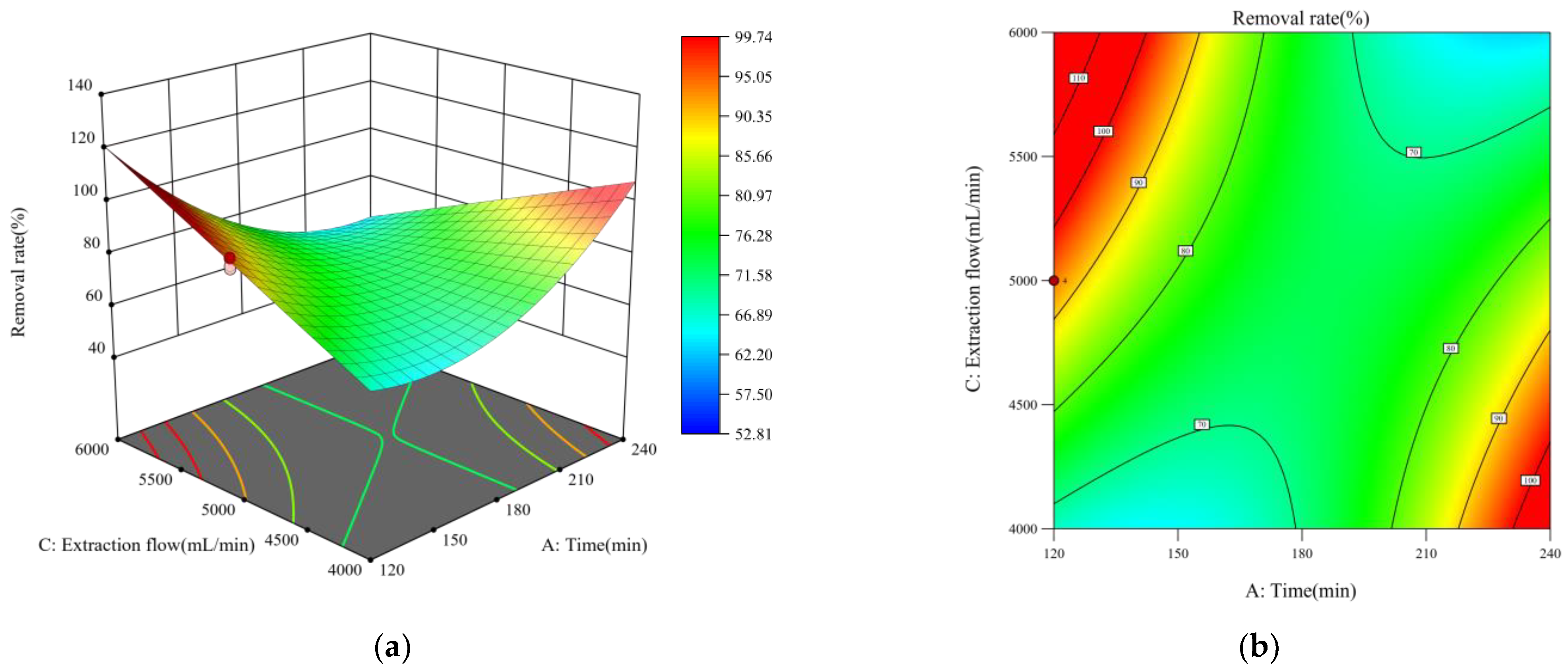
In this experiment, time, temperature, extraction flow, and contaminant concentration were used as the test variables, and the removal rate was used as the response value Y [38]. The response surface analysis is performed on the test results in Table 9, and the response surface plots and contour plots of the effect of the interaction terms on the removal rate can be obtained, which are shown in Figure 6 and Figure 7 [39]. In these plots, the two factors differ, while the other factors remain constant at their mean values. There are significant interactions between time and temperature and between time and extraction flow [40]. The interaction effect of time/temperature has a considerable negative cooperative effect on the target variable. The multiple quadratic regression model for the removal rate is as follows.
Y = −112.95417 + 0.425618 × A + 0.811833 × B + 0.076059 × C−11.0925 × D−0.007715 × A × B−0.00041 × A × C + 0.004734 × A2,
As shown in Table 9, the regression model is subjected to ANOVA and the significance test is performed on the regression coefficients. First, the model p-value is less than 0.0001, which indicates that the model equation is significant and well correlated. Meanwhile, the “lack of fit f-value” of 0.0859 indicates the lack of fit is not significant [41]. In the model, the p-values for A, B, C, and D are less than 0.05, indicating that they have a significant effect on the removal rate. There is a greater influence of D than A, B, or C on the removal rate. The “R-Squared” is 0.9803 and the “Pred R-Squared” of 0.9662 is a good approximation to the “Adj R-Squared” of 0.9754, indicating that the model fits well. The CV-value for the model is only 2.8% (less than 10%), which indicates the model has a high degree of confidence and the model equation is able to better reflect the experimental data. The signal-to-noise ratio is measured by the “Adeq Precision”, and a ratio over four is considered desirable, therefore the ratio of 37.2404 in this model is sensible [42]. In conclusion, the model adequately reflects the actual correlation between removal rate and process parameters.
Figure 8a shows a comparison of the predicted removal rate from the simplified model with the actual measured value. The predicted values of the model (removal rate, %) are in good agreement with the observed values from the experiments. Additionally, Figure 8b shows a plot of residuals versus predicted responses. As can be seen, the distribution of the residuals is random with no trend. Based on these results, it can be concluded that the proposed model is the most reasonable and accurate way to describe the relationship between variables and responses, and is enough to assess the impact of variables.
The optimal conditions for the removal of ethylbenzene could be obtained by maximizing the “desirability function” [43,44,45]. The experimental combination that maximizes the desirability function includes the best combination of test 5 derived from the range analysis, i.e., the optimal removal conditions are time: 180 min, temperature: 20 °C, extraction flow: 6000 mL/min, and contaminant concentration: 2%.

3.5. Simulation

Based on the previous discussion, the optimal combination (A2B2C3D1, time: 180 min, temperature: 20 °C, extraction flow: 6000 mL/min, contaminant concentration: 2%) was simulated with a three-dimensional model using COMSOL software, and the numerical model was dimensionally consistent with the experimental model. The simulation of this physical field requires the following assumptions: (1) the porous medium of this physical field is a homogeneous medium with isotropic density, homogeneity of pores, and permeability; (2) air in the homogeneous medium is neglected and the porous medium is assumed to be saturated and the pores are filled with contaminants; (3) the negative pressure generated by the pumping borehole acts uniformly on the surrounding medium and the boundary fluid flow is laminar; (4) the medium temperature of the site is uniformly consistent at 293.15 K (20 °C).
The boundary conditions and initial conditions were set as follows [17]: (1) The entire boundary of the SVE thermal reaction unit is thermally insulated and closed, and only the borehole opening on the top surface is open; (2) the initial pollutant concentration is 140 mg/g; (3) the displacement component of all points on the boundary is always 0.
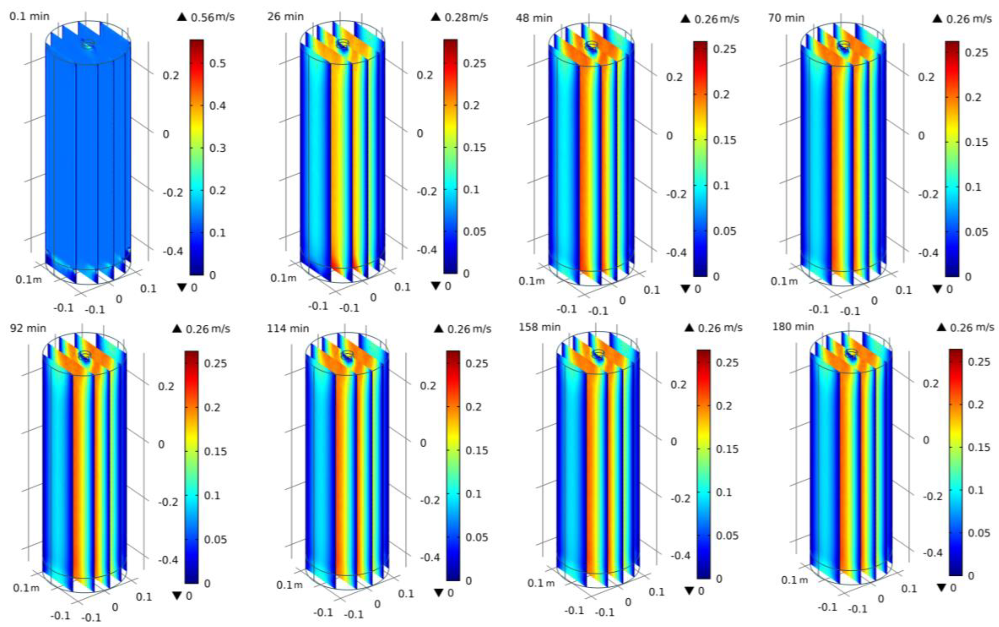
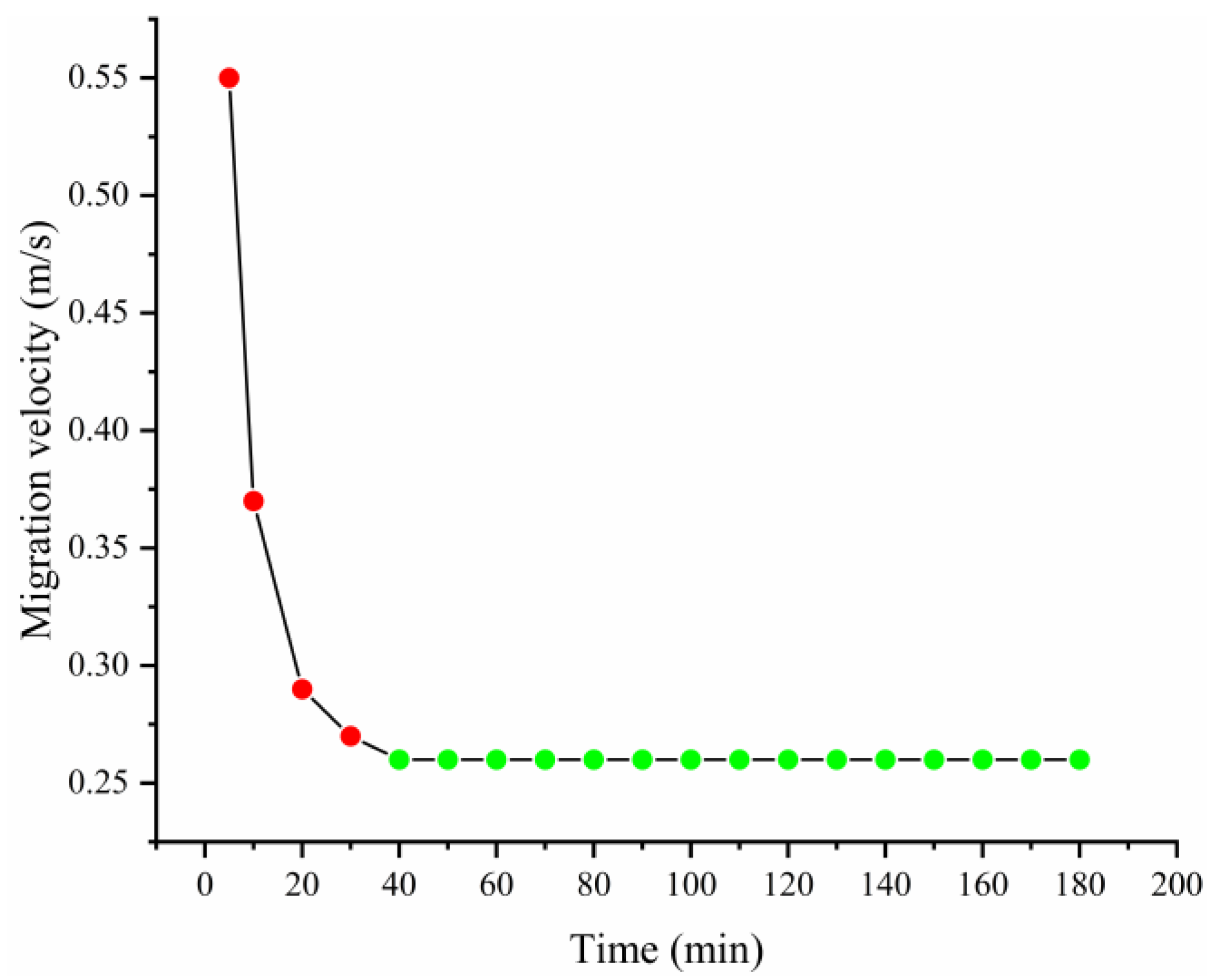
The state of contaminant migration is characterized by the flow rate of the fluid. The contaminant migration variation is shown in Figure 9. The maximum velocity of contaminant migration over the whole simulation period is shown in Figure 10. It can be seen that the maximum velocity of contaminant migration in 10–20 min decreases from 0.37 m/s to 0.29 m/s and the largest decline occurs; in 20–40 min, the maximum velocity of pollutant migration gradually decreases to 0.26 m/s; in 40–180 min, it is stable at 0.26 m/s. The above phenomenon shows that, in the SVE numerical model, the contaminant at the beginning volatilizes under the effect of high temperature, so the migration rate is fast. At the later stage, the migration rate remains stable, most likely because the contaminant concentration decreases slowly. The residual contaminants remain in the soil in the adsorbed state, and a tailing effect appears. Generally, this phenomenon is consistent with most of the soil column experiments.

4. Conclusions

In this work, a one-dimensional SVE thermal reaction experimental model was constructed and the effects of time, temperature, extraction flow rate, and pollutant concentration on the performance of SVE were investigated using an orthogonal experimental method and response surface analysis. In addition, the pollutant migration pattern was investigated by numerical simulation based on the experimental results, and the conclusions are as follows.
  • Based on the range analysis and the first-order kinetic reaction model, it can be concluded that test 5 (A2B2C3D1) is the optimal combination, and in addition, the half-life performance in test 3 and test 5 is better than the other groups.
  • ANOVA and Duncan’s new multiple range tests showed that the effect of factors on SVE was greater than the fluctuation of data caused by errors, and four factors were significant or highly significant.
  • Response surface analysis showed that time, temperature, and extraction flow rate had a positive effect on the removal rate, while the interaction of time with temperature and time with extraction flow rate had a very significant negative effect. In addition, the optimal remediation conditions were: time 180 min, temperature 20 °C, extraction flow rate 6000 mL/min, and contaminant concentration 2%.
  • The isometric numerical simulation showed that the maximum rate of contaminant migration remained stable after the model was heated for 40 min under the optimal combination of conditions, and a trailing effect was also observed.

Author Contributions

Conceptualization, S.Z. and Y.C.; methodology, S.Z. and Y.C.; software, S.Z. and Y.C.; validation, S.Z., Y.C., and W.L.; formal analysis, S.Z. and Y.C.; investigation, Z.L.; resources, R.S.; data curation, R.S.; writing—original draft preparation, S.Z. and Y.C.; writing—review and editing, S.Z., Y.C., and Z.L.; visualization, S.Z. and Y.C.; supervision, S.Z. and Z.L.; project administration, R.S.; funding acquisition, Z.L. All authors have read and agreed to the published version of the manuscript.

Funding

This research was funded by the National Natural Science Foundation of China (Grant No. 51974359) and the Postgraduate Scientific Research Innovation Project of Hunan Province (Grant No. CX20220205).

Institutional Review Board Statement

Not applicable.

Informed Consent Statement

Not applicable.

Data Availability Statement

Not applicable.

Conflicts of Interest

The authors declare no conflict of interest.

References

  1. Zhang, Q.; Feng, Q.; Zhu, X.; Zhang, M.; Wang, Y.; Yang, L. Box Experiment Study of Thermally Enhanced SVE for Benzene. Int. J. Environ. Res. Public Health 2021, 18, 4062. [Google Scholar] [CrossRef] [PubMed]
  2. Ding, X.-H.; Feng, S.-J.; Zheng, Q.-T.; Peng, C.-H.; Zhu, Z.-W.; Yang, C.-B. Transient migration behavior of VOC vapor in layered unsaturated soils subjected to multiple time-dependent point pollution sources: Analytical study. Sci. Total Environ. 2022, 806, 150370. [Google Scholar] [CrossRef] [PubMed]
  3. Chen, Y. Study on Typical Influencing Factors of Non-Aqueous Pollutants in SVE Technology. Master’s Thesis, China University of Mining and Technology, Xuzhou, China, 2019. [Google Scholar]
  4. Yang, Y.; Wang, C.; Sha, X.; Song, M.; Sang, Y.; Zhu, L. Desorption kinetics of thermal enhanced soil vapor extraction technology used in hydrocarbon contaminated soil. Chin. J. Environ. Eng. 2019, 13, 2328–2335. [Google Scholar]
  5. Yang, Y.; Li, J.; Xi, B.; Wang, Y.; Tang, J.; Wang, Y.; Zhao, C. Modeling BTEX migration with soil vapor extraction remediation under low-temperature conditions. J. Environ. Manag. 2017, 203, 114–122. [Google Scholar] [CrossRef] [PubMed]
  6. Ding, Y.; Zhang, Y.; Deng, Z.; Song, H.; Wang, J.; Guo, H. An innovative method for soil vapor extraction to improve extraction and tail gas treatment efficiency. Sci. Rep.-UK 2022, 12, 6495. [Google Scholar] [CrossRef] [PubMed]
  7. Shi, J.; Yang, Y.; Li, J.; Xi, B.; Wang, Y.; Wang, Y.; Tang, J. A study of layered-unlayered extraction of benzene in soil by SVE. Environ. Pollut. 2020, 263, 114219. [Google Scholar] [CrossRef] [PubMed]
  8. Yu, Y.; Shao, Z.; Liu, J.; Wen, W.; Yan, Z. Factors influencing remediation of semi-volatile petroleum hydrocarbon-contaminated soil by thermally enhanced soil vapor extraction. Chin. J. Environ. Eng. 2017, 11, 2522–2527. [Google Scholar]
  9. Qin, C.-Y.; Zhao, Y.-S.; Zheng, W.; Li, Y.-S. Study on influencing factors on removal of chlorobenzene from unsaturated zone by soil vapor extraction. J. Hazard. Mater. 2010, 176, 294–299. [Google Scholar] [CrossRef]
  10. Hinchee, R.E.; Dahlen, P.R.; Johnson, P.C.; Burris, D.R. 1,4-Dioxane Soil Remediation Using Enhanced Soil Vapor Extraction: I. Field Demonstration. Groundw. Monit. Remediat. 2018, 38, 40–48. [Google Scholar] [CrossRef]
  11. Poppendieck, D.G.; Loehr, R.C.; Webster, M.T. Predicting hydrocarbon removal from thermally enhanced soil vapor extraction systems: 2. Field study. J. Hazard. Mater. 1999, 69, 95–109. [Google Scholar] [CrossRef]
  12. Lim, M.W.; Von Lau, E.; Poh, P.E. A comprehensive guide of remediation technologies for oil contaminated soil—Present works and future directions. Mar. Pollut. Bull. 2016, 109, 14–45. [Google Scholar] [CrossRef] [PubMed]
  13. Hao, G.; Yong, Q.; Guangxiang, Y.; Chunxiao, W. Research progress on the soil vapor extraction. J. Groundw. Sci. Eng. 2020, 8, 57–66. [Google Scholar]
  14. Labianca, C.; De Gisi, S.; Picardi, F.; Todaro, F.; Notarnicola, M. Remediation of a Petroleum Hydrocarbon-Contaminated Site by Soil Vapor Extraction: A Full-Scale Case Study. Appl. Sci. 2020, 10, 4261. [Google Scholar] [CrossRef]
  15. Yang, X.; Yi, H.; Tang, X.; Zhao, S.; Yang, Z.; Ma, Y.; Feng, T.; Cui, X. Behaviors and kinetics of toluene adsorption-desorption on activated carbons with varying pore structure. J. Environ. Sci. 2018, 67, 104–114. [Google Scholar] [CrossRef]
  16. Wang, Y.; Wang, Y.; Tang, J.; Li, J.; Yang, Y.; Bai, S.; Shi, J. Numerical simulation of SVE in groundwater table fluctuation zone based on TMVOC. China Environ. Sci. 2020, 40, 350–356. [Google Scholar]
  17. Nguyen, V.T.; Zhao, L.; Zytner, R.G. Three-dimensional numerical model for soil vapor extraction. J. Contam. Hydrol. 2013, 147, 82–95. [Google Scholar] [CrossRef] [Green Version]
  18. Rehman, Z.U.; Khalid, U.; Ijaz, N.; Mujtaba, H.; Haider, A.; Farooq, K.; Ijaz, Z. Machine learning-based intelligent modeling of hydraulic conductivity of sandy soils considering a wide range of grain sizes. Eng. Geol. 2022, 311, 106899. [Google Scholar] [CrossRef]
  19. Esrael, D.; Kacem, M.; Benadda, B. Modelling mass transfer during venting/soil vapour extraction: Non-aqueous phase liquid/gas mass transfer coefficient estimation. J. Contam. Hydrol. 2017, 202, 70–79. [Google Scholar] [CrossRef]
  20. Xu, D.; Zhang, Y.; Zhu, L.; Sang, Y. ERH remediation process optimization of organic contaminated soil based on COMSOL simulation. Chin. J. Environ. Eng. 2021, 15, 3642–3650. [Google Scholar]
  21. Yang, Y.; Zhao, C.J.; Li, J.; Bai, S.G.; Xi, B.D.; Tang, J.; Lu, N.Q. Numerical Simulation through SVE Technique based on TMVOC under Low Temperature. Res. Environ. Sci. 2017, 30, 1587–1596. [Google Scholar]
  22. Fen, C.-S.; Cheng, H.-C.; Ku, C.-C. An effective response surface-based optimisation approach for soil vapour extraction system design. Civ. Eng. Environ. Syst. 2008, 25, 227–243. [Google Scholar] [CrossRef]
  23. Fen, C.-S.; Chan, C.; Cheng, H.-C. Assessing a Response Surface-Based Optimization Approach for Soil Vapor Extraction System Design. J. Water Resour. Plan. Manag. 2009, 135, 198–207. [Google Scholar] [CrossRef]
  24. Sabour, M.R.; Jalali, S.H.S.; Dezvareh, G. Comprehensive Model for Remediation of Sandy Soils Contaminated with Volatile Organic Compounds Using Thermal Enhancement of Soil Vapor Extraction Method. Water Air Soil Pollut. 2017, 228, 239. [Google Scholar] [CrossRef]
  25. Wei, Q. Laboratory Experimental Study on Remediation of Vocs-Contaminated Site by Thermal-Enhanced Soil Vapor Extraction. Master’s Thesis, Southeast University, Nanjing, China, 2018. [Google Scholar]
  26. Alyüz, B.; Veli, S. Kinetics and equilibrium studies for the removal of nickel and zinc from aqueous solutions by ion exchange resins. J. Hazard. Mater. 2009, 167, 482–488. [Google Scholar] [CrossRef]
  27. Jin, Z.; Zhang, X.; Li, M.; Qian, C. Crack Self-healing Kinetic Model of Microbial Self-healing Concrete. Mater. Rep. 2020, 34, 1194–1200. [Google Scholar]
  28. Xiang, F. Discussion on Some Issues on Parameter Statistics of First-Order Chemical Kinetics Reaction Equation. J. Ecol. Rural Environ. 1998, 14, 20–25. [Google Scholar]
  29. Cancelli, A.M.; Gobas, F.A. Treatment of naphthenic acids in oil sands process-affected waters with a surface flow treatment wetland: Mass removal, half-life, and toxicity-reduction. Environ. Res. 2022, 213, 113755. [Google Scholar] [CrossRef]
  30. Yuan, L.; Ma, Y.; Zhang, J.; Men, J.; Sun, T.; Zhao, H.; Wu, H.; Wang, H.; Dai, S. Orthogonal analysis and mechanism of compressive strength and microstructure of the metakaolin-fly ash geopolymer. Case Stud. Constr. Mater. 2022, 17, e01154. [Google Scholar] [CrossRef]
  31. Wang, B.; Lin, R.; Liu, D.; Xu, J.; Feng, B. Investigation of the effect of humidity at both electrode on the performance of PEMFC using orthogonal test method. Int. J. Hydrogen Energy 2019, 44, 13737–13743. [Google Scholar] [CrossRef]
  32. Li, D.; Xu, C.; Xiong, Z. Gas flowing model of mining face and solve it using COMSOL. J. China Coal Soc. 2012, 37, 967–971. [Google Scholar]
  33. Shi, Y.; Rui, S.; Xu, S.; Wang, N.; Wang, Y. COMSOL Modeling of Heat Transfer in SVE Process. Environments 2022, 9, 58. [Google Scholar] [CrossRef]
  34. Zhao, L.; Zytner, R.G. Estimation of SVE closure time. J. Hazard. Mater. 2008, 153, 575–581. [Google Scholar] [CrossRef] [PubMed]
  35. Liu, C.; Liu, J.; Guo, P.; Peng, J.; Zhang, L.; Li, Y. Mercury removal from spent low-level mercury catalyst by thermal treatment. Can. J. Chem. Eng. 2022, 100, S236–S245. [Google Scholar] [CrossRef]
  36. Meng, H.; Li, Y.-F.; Zhang, C. Modeling of discharge voltage for lithium-ion batteries through orthogonal experiments at subzero environment. J. Energy Storage 2022, 52, 105058. [Google Scholar] [CrossRef]
  37. Ishrat, S.I.; Khan, Z.A.; Siddiquee, A.N.; Badruddin, I.A.; Algahtani, A.; Javaid, S.; Gupta, R. Optimising Parameters for Expanded Polystyrene Based Pod Production Using Taguchi Method. Mathematics 2019, 7, 847. [Google Scholar] [CrossRef] [Green Version]
  38. Liu, P.; Xiao, X.; Chang, C.; A, D.; Li, Y.; Dong, J.; Zheng, W.; Huang, Q.; Dong, F.; Liu, X.; et al. Study on the Technology of Preparing Magnesium Oxychloride Cement Material by Calcination Extraction of Lithium By-Product Based on Orthogonal Experiment and Response Surface Method. Mater. Rep. 2020, 34, 1308–1314. [Google Scholar]
  39. Khalid, U.; Rehman, Z.U.; Mujtaba, H.; Farooq, K. 3D response surface modeling based in-situ assessment of physico-mechanical characteristics of alluvial soils using dynamic cone penetrometer. Transp. Geotech. 2022, 36, 100781. [Google Scholar] [CrossRef]
  40. Di, J.; Wang, M.; Zhu, Z. Experiment on the treatment of acid mine drainage with optimized biomedical stone particles by response surface methodology. Environ. Sci. Pollut. Res. 2018, 25, 7978–7990. [Google Scholar] [CrossRef]
  41. Zhu, T.; Shen, Q.; Xu, Y.; Li, C. Ionic liquid and ultrasound-assisted extraction of chestnut shell pigment with good hair dyeing capability. J. Clean. Prod. 2022, 335, 130195. [Google Scholar] [CrossRef]
  42. Rehman, Z.U.; Khalid, U. Optimization of COVID-19 face mask waste fibers and silica fume as a balanced mechanical ameliorator of fat clay using response surface methodology. Environ. Sci. Pollut. Res. 2022, 29, 17001–17016. [Google Scholar] [CrossRef]
  43. Modesto, H.R.; Lemos, S.G.; dos Santos, M.S.; Komatsu, J.S.; Goncalves, M.; Carvalho, W.A.; Carrilho, E.N.V.M.; Labuto, G. Activated carbon production from industrial yeast residue to boost up circular bioeconomy. Environ. Sci. Pollut. Res. 2021, 28, 24694–24705. [Google Scholar] [CrossRef] [PubMed]
  44. Pereira, L.; Maranhão, T.D.A.; Frescura, V.L.A.; Borges, D.L.G. Multivariate assessment of extraction conditions for the fractionation analysis of mercury in oily sludge samples using cold vapor atomic fluorescence spectrometry. J. Anal. At. Spectrom. 2019, 34, 1932–1941. [Google Scholar] [CrossRef]
  45. Roosta, M.; Ghaedi, M.; Daneshfar, A.; Sahraei, R. Experimental design based response surface methodology optimization of ultrasonic assisted adsorption of safaranin O by tin sulfide nanoparticle loaded on activated carbon. Spectrochim. Acta Part A Mol. Biomol. Spectrosc. 2014, 122, 223–231. [Google Scholar] [CrossRef] [PubMed]
Figure 1. Location of the sampling point.
Sustainability 15 01168 g001
Figure 2. (a) Schematic diagram of SVE system; (b) SVE glassy soil column.
Sustainability 15 01168 g002
Figure 3. First-order kinetic reaction model fitting and pollutant removal rate in nine tests: (a) Test 1; (b) Test 2; (c) Test 3; (d) Test 4; (e) Test 5; (f) Test 6; (g) Test 7; (h) Test 8; (i) Test 9.
Sustainability 15 01168 g003
Figure 4. Cumulative bar graph of the half-life for 9 tests.
Sustainability 15 01168 g004
Figure 5. The variation in indicators at different factors.
Sustainability 15 01168 g005
Figure 6. Interaction effects of temperature and time. Extraction flow and pollutant concentration were maintained constant at 5000 mL/min and 4%, respectively. (a) 3D surface; (b) Contour plot.
Sustainability 15 01168 g006
Figure 7. Interaction effects of extraction flow and time. Temperature and pollutant concentration were maintained constant at 20 °C and 4%, respectively. (a) 3D surface; (b) Contour plot.
Sustainability 15 01168 g007
Figure 8. (a) Comparison of theoretical and experimental data; (b) Residual plots of response values, obtained from ANOVA test.
Sustainability 15 01168 g008
Figure 9. Finite element simulation of pollutant removal process in test 5 (A2B2C3D1, time: 180 min, temperature: 20 °C, extraction flow: 6000 mL/min, pollutant concentration: 2%).
Sustainability 15 01168 g009
Figure 10. The contaminant migration velocity under different times.
Sustainability 15 01168 g010
Table 1. Basic properties of soil sample.
Silt (%)Clay (%)Sand (%)Moisture Content (%)Organic Matter (%)Surface Area (m2/g)Micropore Volume (mL/g)pH
67.416.17.25.53.82.660.0127.9
Table 2. Orthogonal factor and level list.
LevelFactor
A (min)B (°C)C (mL/min)D (%)
11201040002
21202050004
31203060006
Table 3. L9(34) orthogonal array.
TestFactor
A (min)B (°C)C (mL/min)D (%)
11111
21222
31333
42123
52231
62312
73132
83213
93321
Table 4. Input parameters for numerical simulation 3D-SVE model.
MaterialThermal Conductivity/
[W/(m∙K)]
Density/
(kg/m3)
Constant Pressure Heat Capacity/
[J/(kg∙K)]
Volume FractionDynamic Viscosity/
(Pa·s)
Permeability/
m2
Porous medium0.47120010100.82-1.79 × 10⁻³
Contaminant0.12878701696.7-6.09901 × 10⁻⁴-
Table 5. R2 and k in nine tests.
TestR2k
10.955830.01895 ± 0.00154
20.978830.02052 ± 0.00113
30.996960.05433 ± 0.00183
40.961340.00493 ± 1.11893 × 10⁻⁴
50.998750.04178 ± 9.5212 × 10⁻⁴
60.982090.00514 ± 1.6631 × 10⁻⁴
70.983940.00744 ± 2.93013 × 10⁻⁴
80.9850.01023 ± 4.38981 × 10⁻⁴
90.927920.01227 ± 0.00158
Table 6. Orthogonal design scheme and indicators.
TestA (min)B (°C)C (mL/min)D (%)Indicator Ⅰ (Removal Rate %)Indicator Ⅱ (Removal Rate %)Indicator Ⅲ (Removal Rate %)Indicator Ⅳ (Removal Rate %)SumMean
1120104000292.990.4289.1790.55363.0490.76
2120205000495.4095.9092.7391.64375.6793.92
3120306000698.0296.4898.7998.45391.7497.94
4180105000657.0852.8158.9556.82225.6656.42
5180206000298.5097.4498.8894.60389.4297.36
6180304000464.8066.8364.8562.41258.8964.72
7240106000472.4572.4172.8077.17294.8373.71
8240204000689.8585.8485.3281.36342.3785.59
9240305000299.1598.4292.0199.74389.3297.33
Table 7. Results of the range analysis.
IndicatorFactor
A (min)B (°C)C (mL/min)D (%)
K i 1 1130.45883.53964.31141.78
K i 2 873.971107.46990.65929.39
K i 3 1026.521039.951075.99959.77
K i 1 376.82294.51321.43380.59
K i 2 291.32369.15330.22309.80
K i 3 342.17346.65358.66319.92
R i 85.574.6437.2370.79
Table 8. Significance analysis.
FactorSSdfMSFF0.05F0.01Significance
A (Time)2773.7521386.87241.6119.4699.47**
B (Temperature)2199.1521099.58191.56//**
C (extraction flow)568.112284.0549.49//*
D (Contaminant concentration)2198.8921099.45191.54//**
Error155.05275.74////
Sum7894.95353875.69////
When F > F0.01, the significance is **, which means highly significant; when F0.01 > F > F0.05, the significance is *, which means significant.
Table 9. Analysis of the variance for the second-order polynomial model.
SourceSum of SquaresdfMean SquareF-ValueProb > F
Model7739.4171105.63199.03<0.0001significant
A-A450.061450.0681.02<0.0001
B-B266.271266.2747.93<0.0001
C-C43.77143.777.880.009
D-D1687.4511687.45303.76<0.0001
AB64.29164.2911.570.002
AC1811.5511811.55326.1<0.0001
A22323.6912323.69418.29<0.0001
Residual155.54285.56
Lack of Fit0.493110.49310.08590.7717not significant
Pure Error155.05275.74
Cor Total7894.9535
R-Squared = 0.9803; Adj R-Squared = 0.9754; Pred R-Squared = 0.9662; Adeq Precision = 37.2404; C.V. % = 2.8.
Disclaimer/Publisher’s Note: The statements, opinions and data contained in all publications are solely those of the individual author(s) and contributor(s) and not of MDPI and/or the editor(s). MDPI and/or the editor(s) disclaim responsibility for any injury to people or property resulting from any ideas, methods, instructions or products referred to in the content.