Article

Characteristics of Silica Fume Nano Alumina Ternary Blended Mortar

by
Moruf Olalekan Yusuf
Department of Civil Engineering, College of Engineering, University of Hafr Al Batin, P.O. Box 1803, Hafr Al Batin 39524, Saudi Arabia
Sustainability 2023, 15(19), 14615; https://doi.org/10.3390/su151914615
Submission received: 21 September 2023 / Revised: 28 September 2023 / Accepted: 7 October 2023 / Published: 9 October 2023
(This article belongs to the Special Issue Sustainable Construction Materials and Technologies)

Abstract

:
This study investigates the contribution of nano-alumina (nA: 1–3 wt.% binder) to the performance of silica fume (SF-10%) and ordinary Portland cement (OPC) binary blended mortar. Microstructural analysis and qualitative characterizations examined the fresh (workability, setting time) and hardened (compressive strength and thermal resistance; 300 degrees C for 1 h) properties. Nano alumina (nA) contributed positively to the consistency of SF blended mortar but negatively to that of OPC mortar. The presence of nA retarded the reactivity of calcium and the fluid absorption capacity of SF in the fresh mortar. The initial (180 min) and final (220 min) setting times in SF blended mortar were reduced by 18.4 and 21.8%, respectively, upon adding up to 3% nA. The optimum nA was 2% in the SF–nA ternary blended mortar with 3-d and 28-d compressive strengths of 28 and 43.2 MPa, respectively. These values were reduced by 14.3% and 29.4% in SF-OPC (binary) and 25.2% and 16.7% in OPC mortar, respectively. The nepheline and tobermorite in the SF–nA ternary blended binder provided a denser microstructural density than in SF-OPC and OPC mortars. Finally, SF–nA ternary mortar was more susceptible to carbonation due to the presence of aluminum and calcium carbonates, despite its superior performance in thermal resistance and strength compared to SF blended and OPC mortars.

1. Introduction

Supplementary cementitious materials (SCMs) are commonly used in mortar and concrete production to achieve cost efficiency, improvement in strength, enhancement in durability performances, and reduction of solid waste and air pollution. Moreover, the production of carbon dioxide due to the disintegration of limestone during the manufacturing process of ordinary Portland cement (OPC) is of environmental concern owing to its effect on global warming. Meanwhile, SCMs, such as fly ash, silica fume (SF), and other pozzolanic or hydraulic materials, can reduce the volume of disintegrated limestone associated with OPC manufacturing. Pozzolanic materials enhance the strength and durability of concrete due to their fineness and ability to undergo secondary hydration characteristics. Adding SF or nano-silica [1,2,3] to blended concrete causes lower early strength development and consistency due to its fineness and dilution effect in the nucleation sites. Recently, the incorporation of nano-additives such as titanium oxide, nano-silica, zinc oxide, or nano alumina (nA), has gained prominence in facilitating the production of binders with different strength and durability performances [4,5,6,7]. However, it is necessary to further improve the characteristics of silica fume (SF) blended mortar by investigating the effect of nA on the setting time, workability, strength, and thermal resistance.
Moreover, alumina is a very reactive oxide that can react with silica to produce a binder with good strength, improved morphology [4], and thermal and chemical resistant characteristics due to its refractory properties [8]. Aluminum shavings were recently applied in small quantities to achieve significant thermal resistance, reduction in apparent porosity, and attainment of lightweight mortar due to the effervescence of hydrogen gas [9]. Moreover, the use of nA in OPC-based binders reportedly enhances early strength and reduces porosity, particularly in the presence of lime (CaO), such as in GGBFS, due to the possible formation of calcium aluminosilicate hydrate (CASH) [4] and low ettringite [Ca6Al(SO4)3(OH)12·26H2O] composition [10]. Ashok et al. [7] also reported improved fresh and hardened properties of concrete of different grades following the incorporation of nA. In 2022, Prabaharan et al. [11] introduced 2% nA into sillimanite-containing concrete and reported an increase in density. Furthermore, Shao et al. [12] found that alumina dissolution in pore solution induces the formation of ettringite, monosulfate aluminate (MSA—Ca4Al2O6(SO4)·14H2O]), and monocarbonaluminates (MCA—Ca4Al2O7(CO2)·11H2O]). Ettringite is formed by the reaction of MSA with excess sulfate (gypsum), leading to microstructural expansion. If such a sample undergoes carbonation, ettringite shrinks, leading to a reduction in compressive strength due to internal stresses that accompany the formation of aluminum hydroxide (AH3) [13]. Meanwhile, excess CaO results in MSA and AH3 being the dominant products rather than expansive ettringite [10]. Moreover, AH3 within the sample matrix reportedly causes a potential danger due to its propensity to form late ettringite upon reacting with any possible sulfate ingress into the matrix [14,15].
The combined use of nA with other compatible materials could alter the mechanical properties and durability of the binder [13]. More specifically, this could produce concrete or mortar with improved characteristics with far-reaching applications in kitchens, furnaces, ceramics and other heat-resistant structures, especially in the Middle East where the temperature during summer can reach 49 °C [16]. Li et al. [17] utilized nA in the range of 3–7% (optimum: 5%) to enhance the elastic modulus by 143%. Meanwhile, Nazari et al. [18,19] utilized 0.5–2% nA in OPC concrete and reported the optimum strength was achieved with 1% nA. Carmo et al. [20] asserted that 2% nA contributed to the bond strength of steel fiber-reinforced concrete. In addition, Peerzada et al. [4] affirmed that the incorporation of nA increased the strength of concrete by enhancing alite hydration (not belite), however, interfered with the efficiency of the superplasticizer, such that 0.3% nA together with 0.6% superplasticizer (SP) could reduce the workability by 31%. Moreover, Atiq Orakzai [5] reported that the presence of nA and nano titanium oxide provided favorable nucleation sites for calcium silicate hydrate (CSH), controlled the growth of portlandite, and enhance the microstructural density. Krishnaveni et al. [6,21] reported that 1–7% nA in concrete improved the microstructural density through boundary nucleation growth effects thereby accelerating the hydration process. Zhan et al. [22] noted that nA enhanced the reaction of silicate to form mullite, and consequently reduced the micropores.
The performance of alumina in binders depends on its level of crystallinity. Alpha-alumina is reportedly more crystalline than γ -alumina, and the former has more detrimental effects on OPC in a sulfate environment than the latter [13]. Shao et al. [12] reported the possibility of the formation of carbon-based ettringite due to interaction of MSA with atmospheric CO2 [12]. Besides, Shabbar et al. [23] reported that incorporating aluminum in OPC produces aerated concrete with good sound and heat insulation, as well as high-level fire resistance at densities of 1000–2000 kg/m3. Younus et al. [24] recently incorporated nA with slag and fly ash in geopolymer self-compacting concrete, in which the optimum mixture that provided the best mechanical properties comprised 1–1.5% nA and 100% fly ash, however, the workability and setting were reportedly decreased.
Hence, the use of powdered additives and nano-scaled materials can work synergistically with OPC to improve the fresh and mechanical properties of a binder. Despite the numerous studies on using alumina in OPC binder and concrete, the data regarding the impact of nA on SF in ternary blended mortar is limited. In particular, a detailed analysis of its microstructure and qualitative characterization of the binder is lacking. This is necessary to understand the alumina–silica interaction in ternary blended mortar in terms of workability, mechanical characteristics, and thermal resistance. This study provides insights with regards to development of a new stronger and heat-resistant binder for structural retrofitting and construction applications. Ultimately, this can reduce the frequency of repair and the required amount of OPC in reinforced concrete structures. Hence, the findings of this study will provide a sustainable solution to concrete repair in the Middle East due to the significant rise in temperature during the summer.

2. Materials and Methods

2.1. Materials

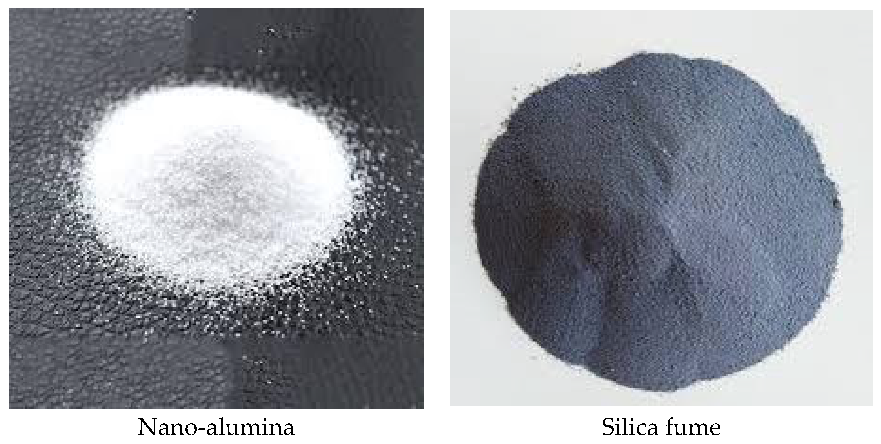
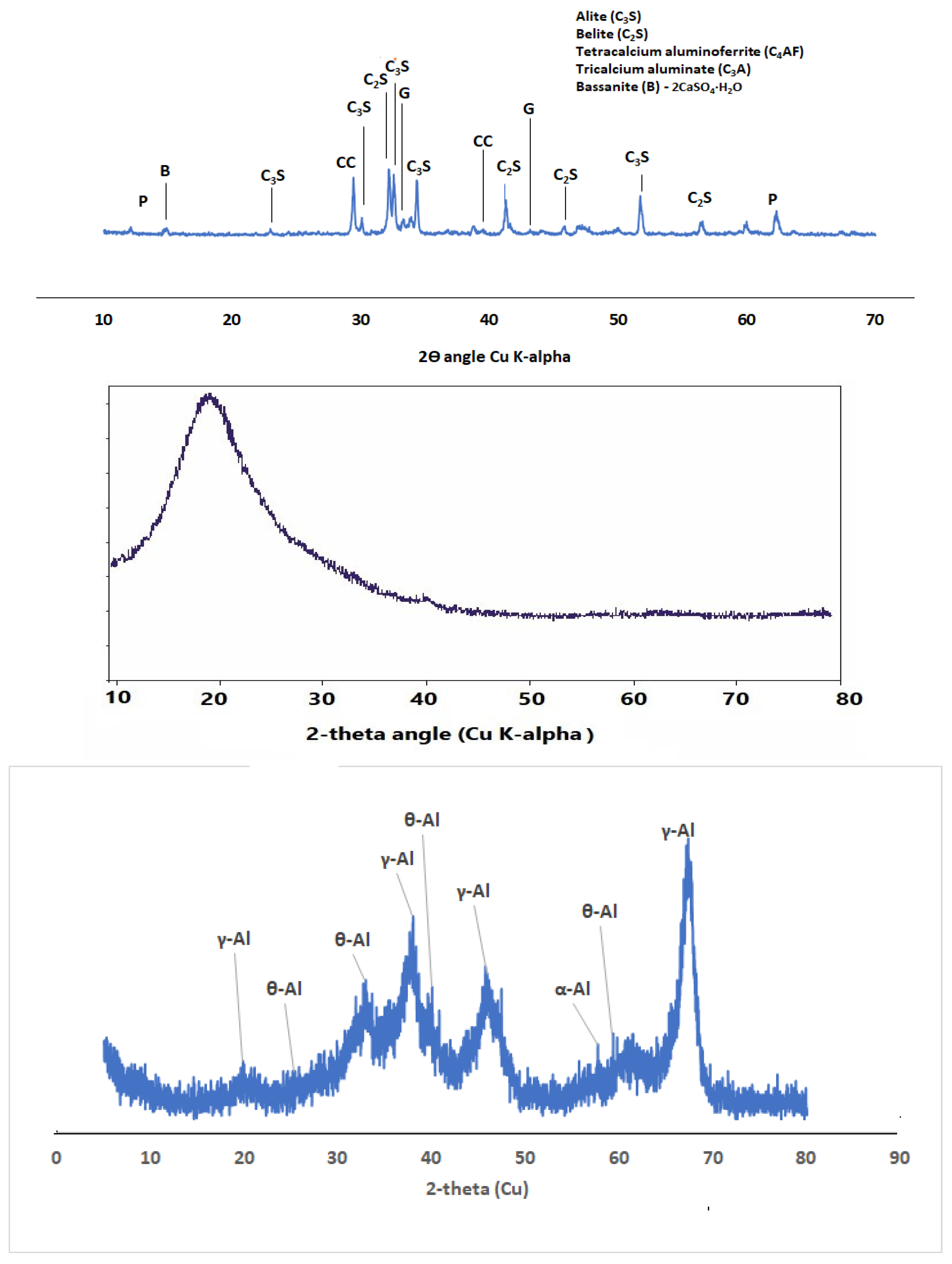
2.1.1. Nano Aluminum Oxide

Nano aluminum oxide was commercially obtained from Aluminium Supplier Company in Saudi Arabia, comprising 99.87% gamma-nano alumina with other oxides in trace amounts (Table 1 and Figure 1). The specific gravity (water) was 3.38, its loss on ignition was 1.05%. while the boiling and melting points were 2977 °C and 2072 °C, respectively. The X-ray diffractogram (XRD) of the nA (Figure 2) indicates that the prominent peaks defining its crystalline phases were mainly γ-alumina, together with θ -alumina and α -alumina.

2.1.2. Cement

Type 1 OPC in compliance with ASTM C 150 with a specific gravity (by water) of 3.15 was used in this study (Table 1). The oxide composition primarily comprised silica, alumina, lime, iron oxide, and potassium oxide. Other oxides in trace amounts included sodium, phosphorus, manganese, and sulfite. Its surface area was 0.329 m2/g, while the loss on ignition (LOI) was 2.8 with the combustion of 28% SiO2 + Al2O3 + Fe2O3. The OPC XRD in Figure 2 presents the peaks of the component compounds that define its crystalline phases, namely: alite, belite, tetracalcium aluminoferrite, and gypsum.

2.1.3. Silica Fume

Silica fume (SF) was commercially obtained with a relative density of 2.25, LOI of 2.48, and surface area of 22.8 m2/g with SiO2 + Al2O3 + Fe2O3 of 96.2% (Table 1). The XRD diffractogram (Figure 2) shows that the SF was primarily amorphous with a diffractive halo at a 2-theta angle of 20 ° .

2.1.4. Aggregates:

The fine aggregate was natural sand in saturated surface dry (SSD) conditions. The absorption and moisture content were 6.14 and 3.43%, respectively. All the sample passed through a sieve no. 2.36 mm (No. 8) in accordance with ASTM C 157/C 157M—08 [25]. The fineness modulus of the fine aggregate was 2.8, while its specific gravity (water) was 2.75.

2.1.5. Superplasticizer

A high-range water-reducing superplasticizer (SP), namely, Glenium(R), produced by BASF company was used at 1 wt% of all the binders (OPC, SF, and nA) to reduce the amount of water required to achieve an adequate consistency.

2.1.6. Water

Potable water with a pH of 7.4 was used to prevent contamination by harmful substances. The water-to-binder ratio was maintained at 0.45.

2.2. Experimental Design

2.2.1. Mix Design

The mix design of the samples is presented in Table 2. The total binder mass was 350 kg/m3 of mortar and was produced with a water-to-binder ratio of 0.45. The nA-to-binder ratio (nA/b) varied from 0 to 3% at a 1% interval while the SF was maintained at 10%.

2.2.2. Sample Designation

The samples comprised OPC (88–100%), nA (0, 1, 2, and 3%), and a constant SF proportion (10%). For instance, the ternary blended sample was described as C90-xS10Ax such that 88% OPC, 10% SF, and 1% nA were designated as C89S10A1. The binary blend containing SF and OPC only was designated C90S10A0, while the control sample comprising only OPC was C100SF0A0.

2.2.3. Mixing Procedure

OPC and SF were mixed before adding nA, after which 50% of the liquid (mixture of water and superplasticizers) was added for ~3 min. Subsequently, sand and 25% of the liquid was added for another 3 min. The remaining water was added, and the mixture was continuously mixed for an additional 2 min to achieve homogeneity. The flow table test was then conducted as a measure of workability before the samples were cast into the molds. The samples were covered with a polythene sheet and then cured in a water tank at room temperature (25 °C).

2.3. Experimental Tests

2.3.1. Setting Time

The initial and final setting times for all samples were determined using paste specimens according to ASTMC 191 [26] with an OPC-mortar only served as the control. Using Vicat’s apparatus, the nA percentage varied from 0 to 3% at a 1% interval, while SF was maintained at 10%.

2.3.2. Workability

The consistency of the mortar was assessed using the flow table in accordance with ASTM C 1437-20 [27]. The diameter of the flow was recorded in each mix.

2.3.3. Compressive Strength

The compressive strength of the samples (50 mm cube) was determined in accordance with ASTM C 109 [28]. In brief, a universal testing machine was used at different timepoints (7, 14, 21, and 28 days) under a 2.4 kN/s loading rate; the average of triplicate samples was recorded.

2.3.4. Residual Compressive Strength after Thermal Exposure

The residual thermal strengths were determined by exposing the 28-day samples to 300 °C for 1 h. Thereafter, the residual strength of the nA–SF ternary blended mortar was compared to that of SF binary blended samples and the control (OPC only).

2.3.5. Characterization and Morphology of the Specimens

The crystallinity of the sample was determined using the XRD Bruker apparatus model d2-Phaser with Cu Ka radiation (40 kV, 30 mA). In this way, the compounds present in the OPC, SF binary blended, and SF–nA ternary blended mortar were determined by applying a scanning speed of 2.5°/min and continuous scanning with a 2-theta angle range of 5–80°. Fourier transform infrared (FTIR) spectroscopy analysis of the paste samples was conducted using the Perkin Elmer 880 spectrometer [29]. The morphology and elemental compositions of the powder materials were determined via a scanning electron microscopy and energy dispersive spectroscopy (SEM + EDS) instrument (JEOL, model 5800 LV) at an accelerating voltage of 20 kV.

3. Discussion of Results

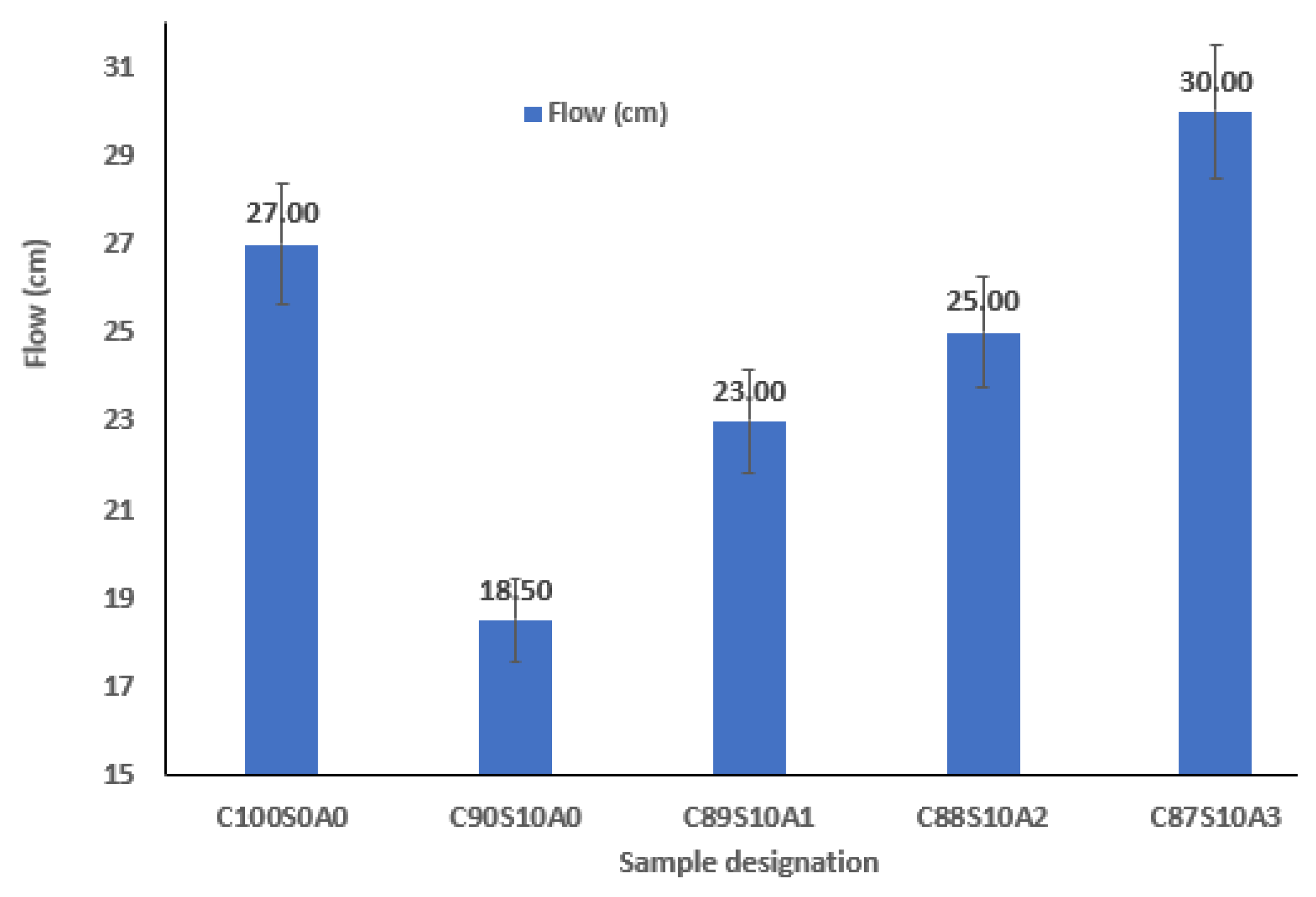
3.1. Workability of Nano Alumina/Silica Fume Ternary Blended Mortar

Introducing SF into OPC mortar reduced its workability due to its fineness and interparticle frictional resistance, negatively affecting the consistency (Figure 3). Binders with SF exhibit a loss of fluidity compared to those without SF. The flow recorded in the OPC mortar (C100S0A0) was 270 mm, which was reduced by 31.5, 14.8, 7.4, and 11.1% upon adding 0, 1, 2, and 3% nA with 10% SF (C90S10A0, C89S10A1, C88S10A2, and C87S10A3), respectively, in the ternary blend. Meanwhile, the consistency of the SF blended mortar (C90S10A0) upon adding 1, 2, and 3% nA increased by 24.3, 35.1, and 62.2%, respectively. This implies that nA significantly improved the interparticle lubrication and workability of SF blended mortar significantly. Hence, the loss of fluidity in SF blended binders could be improved by incorporating nA.

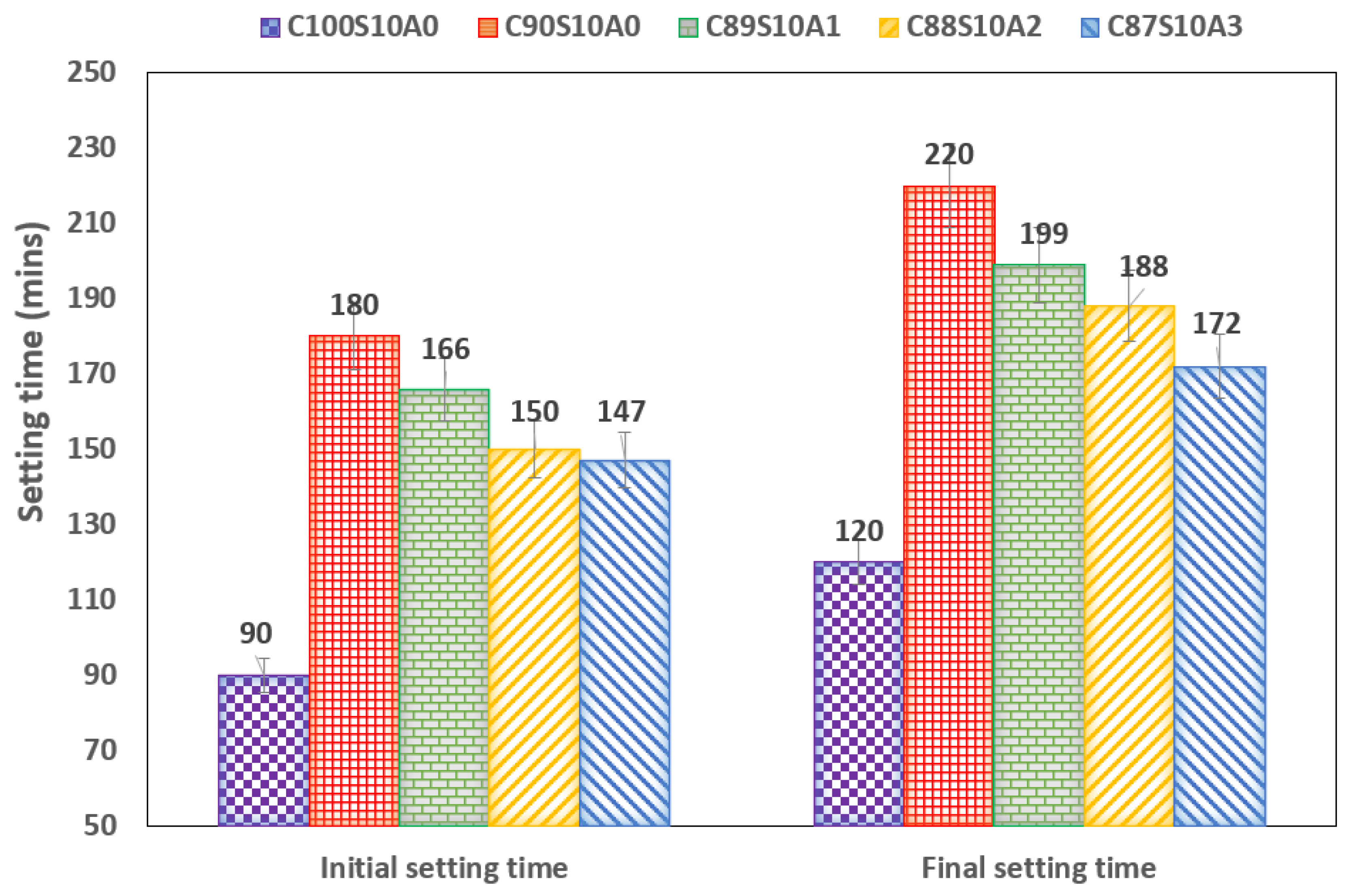
3.2. Setting Time of the SF Blended and Nano Alumina Silica Fume Blended Mortar

Figure 4 shows the setting time of SF blended mortar with the initial setting time of the control sample (OPC only: C100S0A0) set to 90 min. Upon adding 10% SF, the setting time of the OPC binder doubled, while the SF–nA ternary blended paste increased it by 84, 67, and 63% in C89S10A1, C88S10A2, and C87S10A3, respectively, compared to the control. The SF blend (C90S10A0) had an initial setting time of 180 min, which was reduced by 8, 17, and 18% upon adding nA in C89S10A1, C88S10A2, and C87S10A3, respectively. The final setting time of the OPC binder (C100S0A0) was 120 min, which increased by 83% upon adding 10% SF (C90S10A0). The synergy of 10% SF and 1–3% nA paste increased the setting time of OPC by 66, 57, and 43%, respectively. However, SF blended paste (C90S10A0) containing 1–3 wt.% nA reduced the setting time by 10, 15, and 22%, respectively. No significant differences were observed in the initial setting time for C88S10A2 and C87S10A3, while the decreasing trend was relatively linear in initial and final setting times (Figure 4). This implies that nA can be used in ternary blending to accelerate the delayed setting of SF blended binders. The presence of nA reportedly increases the heat of hydration, inducing flash setting [30]. Hence, mechanistically, the setting time was reduced due to the dual consumption of gypsum by tricalcium aluminate (C3A) and gamma nA to form early ettringite (Equation (1)), and the monosulfoaluminate compound due to rapid consumption of the gypsum component [30] in the presence of more alumina compound (C3A), as depicted in Equation (2):
C 3 A + 3 [ C S ¯ . 2 H 2 O ] + 26 H 2 O C 6 A S ¯ 3 . 32 H 2 O
C 3 A + C 6 AS 3 . 32 H 2 O     3 [ C 4 A S ¯ . 12 H 2 O ]

3.3. Compressive Strength of SF–nA Ternary Blended Mortar

Figure 5 shows strength development in OPC, SF blended, and SF–nA ternary blended mortar. The incorporation of 10% SF significantly diminished the early compressive strength of the mortar, while infusing nA in synergistic ternary blending had the opposite effect. The early (3-d) strength of OPC was 20 MPa, which increased by 20% in SF binary (C90S10A0) and by 38.1% and 59% in C88S10A2 and C87S10A3, respectively. A significant strength development was observed between 3 and 7 days in OPC mortar, whereas no concomitant strength development was detected in SF blended mortar. This indicated that no spontaneous pozzolanic reaction occurred within one week in SF blended mortar, as secondary hydration begins after forming portlandite as a product of primary hydration. The absence of calcium aluminate or mayenite (COD: #2102957, Al4Ca12O33) in the SF blended mortar could be responsible for the observable low-early strength.
With the incorporation of 1% nA (C89S10A1), there was no significant increase in the compressive strength. However, when nA increased to 2% or 3% (C87/88S10A2-3), the strength increased by 36.5 and 37.2%, respectively, compared to C90S10A0. The reaction between nA and silica, as observed in C90-xS10Ax, led to the formation of aluminosilicate crystalline phases (dickite: Al2O5Si or nepheline: NaAlO4Si) with COD#10111062 and COD#1008755, respectively (Figure 6).
Calcium aluminate hydrate (CAH) or calcium aluminosilicate hydrate (CASH) could have been created, which could serve as a skeletal framework with calcium silicate hydrate (COD ID #1519934: CSH-Ca3.22H2O8Si2) as demonstrated by Equation (3). Additionally, due to the presence of silica, lime, and nA in an alkaline pore solution, tobermorite (COD ID: 9013974: Ca5Si6(O, OH)18.5H2O), a form of C-S-H with a lower Ca/Si ratio, could also simultaneously form, as represented by Equation (4):
2Al + 3Ca(OH)2 + SiO2 + 6H2O → 3CaO.Al2O3.SiO2.6H2O + 3H2
C3S + H → CSH + CH
Unlike other sources of alumina, such as aluminum shaving [9], where hydrogen gas is liberated, resulting in loss of weight, no noticeable hydrogen gas effervescence was observed following the use of 1–3 wt.% nA.
The dual presence of CSH and tobermorite with calcium aluminate hydrate could significantly contribute to the compressive strength of the ternary (SF–nA) blended mortar. This assertion is corroborated by the presence of calcium aluminate in the XRD diffractogram shown in Figure 6. Therefore, compounds like tobermorite, nepheline, calcium aluminate hydrate, and dickite could be responsible for the observed additional strength. That is, portlandite is readily available to react with alumina to produce free calcium aluminate in the presence of SF, which could induce the formation of additional calcium silicate hydrate. Meanwhile, the 28-d compressive strength of 43.2 MPa was achieved with 2% nA, beyond which led to reduced strength due to microstructural porosity. Hence, the optimum nA proportion in the ternary blended mortar was 2% (Figure 7 and Figure 8).
The strength development in the nA and SF ternary system could also be due to microfilling or micro reinforcement of the micropores (capillary pores) within the nucleation site during the hydration process [5]. Upon adding 2% nA, the microstructure became denser, culminating in increased compressive strength within the SF–nA ternary blended mortar (Figure 7). The denser microstructure in SF–nA mortar might have also been due to Al displacing Ca from Portlandite (CH) to form hydroxide that could later react with CO2 to form aluminum carbonate and calcium carbonate, as represented by Equations (5) and (6):
Al2O3 + 3Ca(OH)2 + 3CO2 → 3CaCO3 + 2Al(OH)3 + 3H2
2Al(OH)3 + 3 CO2 → Al2(CO3)3 + 3H2O
The XRD diffractogram also showed that the SF blended binder might be less susceptible to carbonation based on the presence of a calcite peak (COD ID: #1010962, CaCO3) in Figure 6; however, this peak was conspicuous in the SF–nA blended sample. The presence of pores in the morphology of the OPC-SF-3% alumina sample compared to OPC-SF-2% alumina corroborated this assertion (Figure 8). Based on Equation (5), Al(OH)3 could react with hydroxy ions to form 2[Al(OH)6]3− [31], which in turn would react with capillary water and Ca ions to produce calcium aluminate hydroxide, as demonstrated in Equation (7):
2[Al(OH)6]3− + 6Ca2+ + 24H2O → {Ca6[Al(OH)6]2.24H2O}6+
The product could also react with silica to produce calcium aluminosilicate hydrate or react with other cations present in the matrix to produce a biotite-like mineral (COD: #1000038, AlFeH2KMg2O12Si3), as shown in Figure 6. Additionally, other peaks of unreacted particles, including alite (COD: #1540704, Ca3SiO5) and gypsum (COD: #1010981, CaH4O6S), were among the prominent peaks in Figure 6.

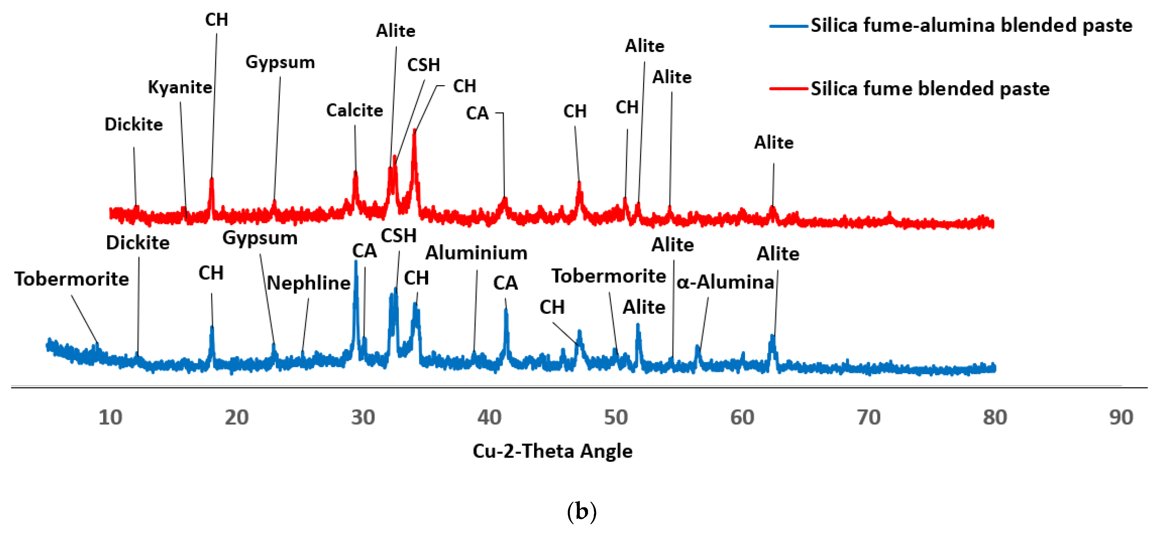
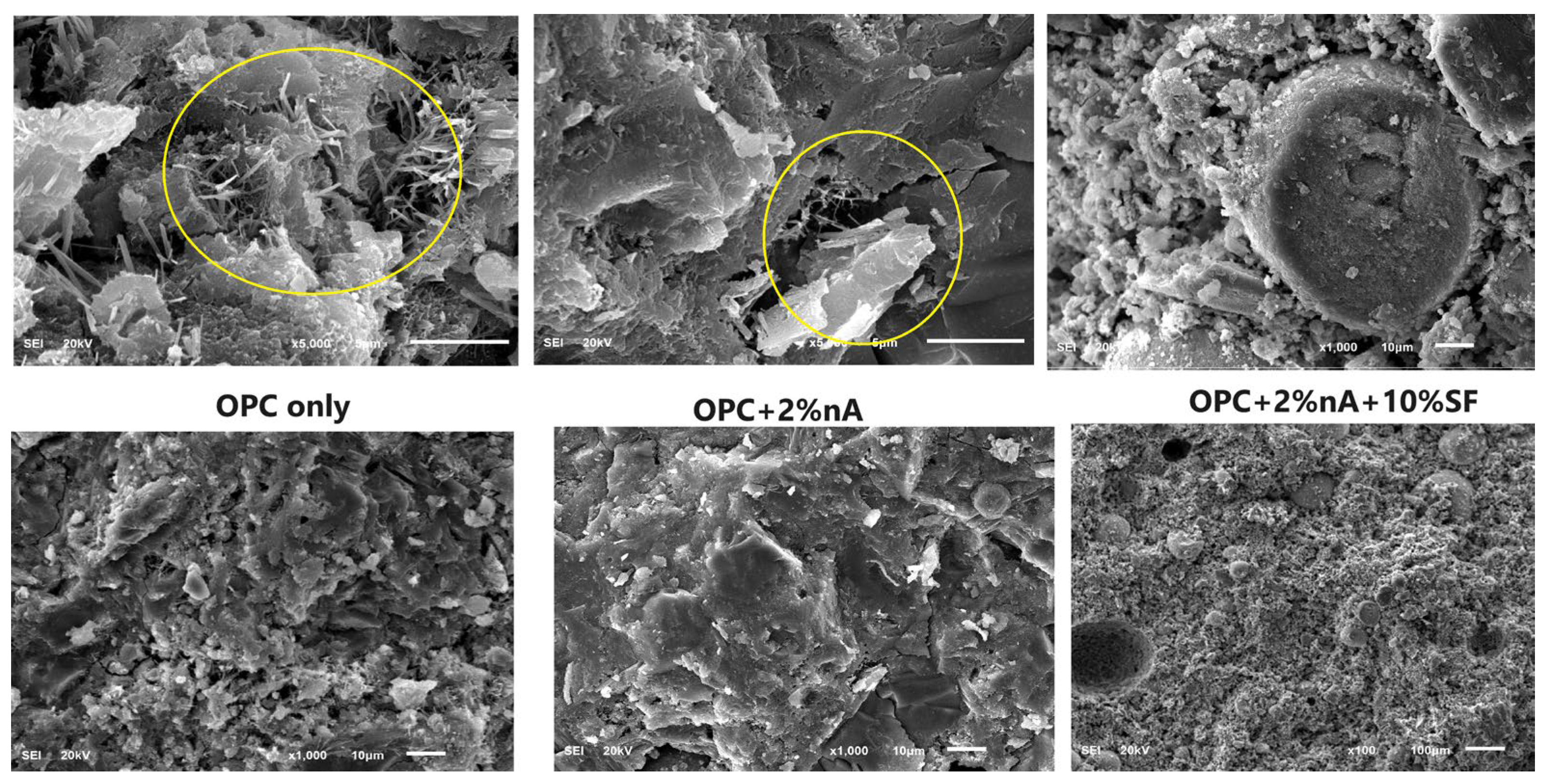
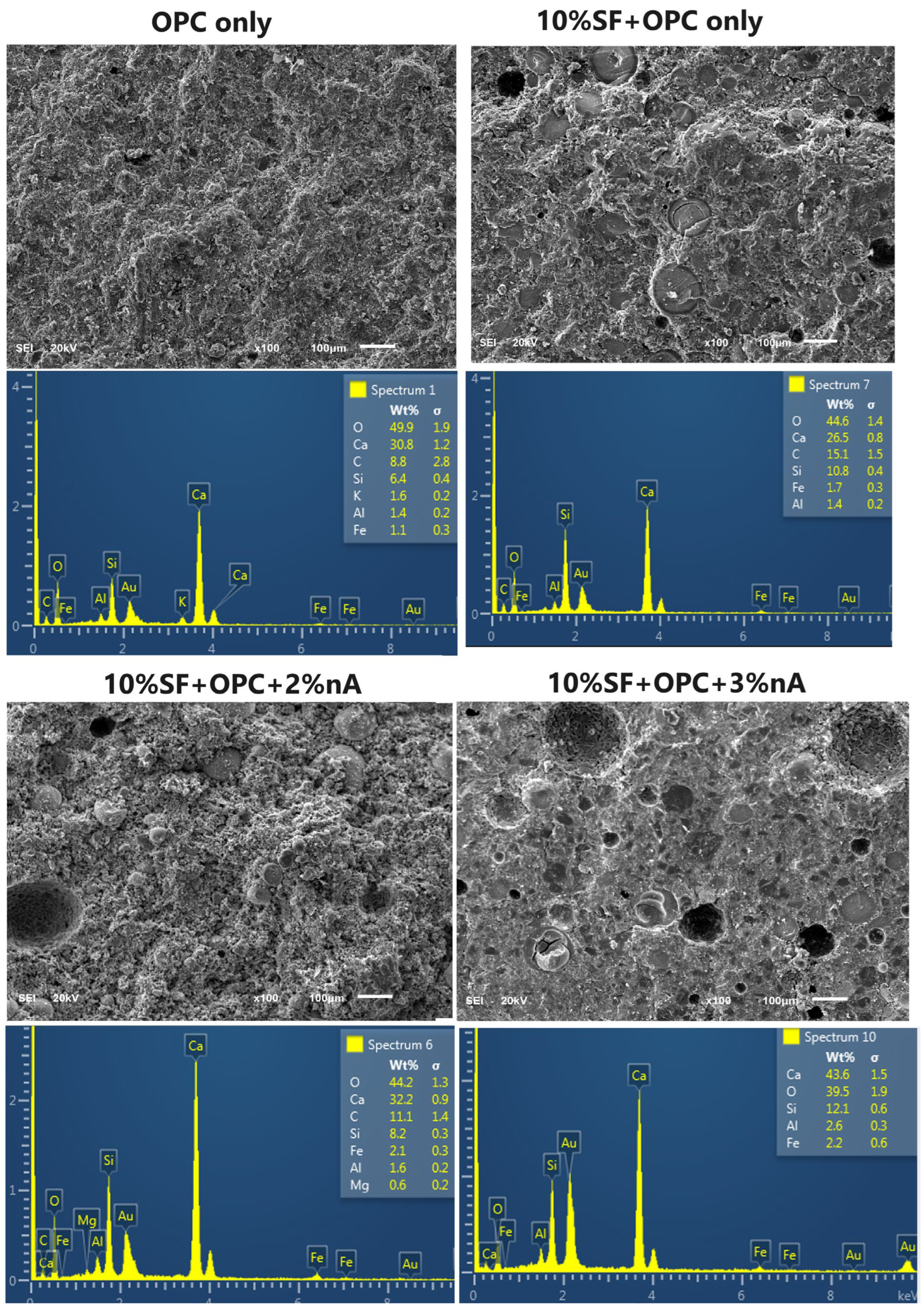
3.4. Morphology of SF Blended Binary and SF–nA Ternary Blended Pastes

Figure 8 shows the different morphologies of nA-treated binders with and without SF. The morphology of OPC (OPC only) is very weak, with excessive needle-like ettringite formation. Meanwhile, nA blocked the pores, forming a denser texture with visible ettringite formation (Aft). Upon combined SF and nA addition in ternary blending with OPC, the microstructural density was more pronounced with a complete loss of Aft. Meanwhile, the transition interface zone of the SF particle and cement matrix might have been filled by nA.
This microstructural density contributed significantly to the compressive strength of the ternary blended (SF and nA) mortar. However, increasing the nA content beyond 2% led to the formation of more micropores, as evident in the SF-3%Al morphology (Figure 7). The reduction in strength could be due to the internal pores in C87S10A3 compared to C88S10A2. The presence of pores within the microstructure enhanced the interconnectivity of the micro-cracks (Figure 7), reducing the sample’s compressive strength. Moreover, the presence of these interconnected pores (Figure 7) in samples with high nA could compromise the thermal resistance of the sample exposed to higher temperatures, as discussed in Section 3.6. Hence, the residual thermal strength in 2% nA samples was superior to those containing 3% nA.
From the EDS results shown in Table 3 for OPC (C100S0A0), SF + OPC (C90S10A0), SF + 2% nA + OPC (C88S10A2), and OPC + nA (without SF), it is apparent that compared to the SF blended sample, introducing nA to SF–nA increases the Ca/Al and Ca/Si ratios, while reducing the Si/Al ratio. These three parameters (Ca/Al, Ca/Si, and Si/Al) were lower in SF–nA compared to the OPC binder. Therefore, the formation of tobermorite in the SF–nA ternary binder (Figure 6) is associated with reduced Ca/Si and Si/Al ratios.

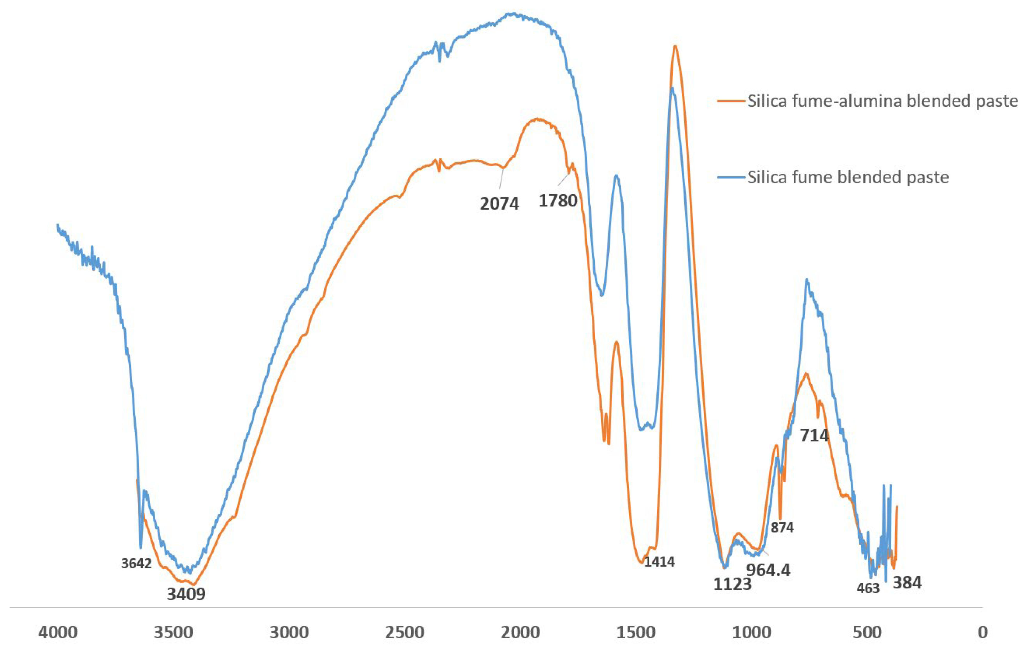
3.5. FTIR of SF Binary and SF–nA Ternary Binder

The FTIR spectroscopy in Figure 9 shows that the prominent peaks distinguishing the SF blended and SF–nA blended binder samples include those at 3642, 2074, 1780, 874, and 714 cm−1. The octahedral stretching O-A-O band corresponds to 463 cm−1. Meanwhile, the Si-O-T (T: Si or Al) vibrations at 1123 cm−1 that originated from CSH and C/NASH [29], [32] appeared identical due to the overlapping spectra in the range of 1100 to 1150 cm−1. Similarly, the hydroxyl bond (-OH) vibration was similar at 3409 cm−1. The asymmetric stretching of CO—from a calcite source—had a stronger peak in SF–nA blended binder at 1414 cm−1 and 1780 cm−1. The out-of-plane and in-plane bending vibrations corresponded to peaks at 874 cm−1 and 714 cm−1, respectively [31]. This further supports the strong calcite peak in Figure 6 and the ternary blended binder containing nA could be more prone to carbonation. Meanwhile, the H-O-H vibration was represented by the 3642 cm−1 peak in the SF blended binder; however, this was absent in the SF–nA blended mortar. This might be due to the penetration of nA into the gel and capillary pores following the interaction of CH with SF and nA during the primary and secondary hydration reactions. This assertion requires further verification through advanced cement chemistry and quantitative FTIR analysis that are beyond the scope of this study.

3.6. Thermal Performance of SF Binary and SF–nA Ternary Blended Mortar

Following exposure of all samples to 300 °C for 1 h, SF–nA ternary mortar exhibited significant thermal stability and resistance compared to SF binary and OPC binders. Upon exposure of the binders to thermal conditions, OPC lost 33.33% of its 28-d compressive strength while the SF binary binder (C90S10A0) lost ~8.85% (Figure 10). Incorporating 1, 2, and 3% nA in the SF–nA ternary binder resulted in 14.9, 3.70, and 9.84% losses of strength respectively. This implies that the mortar synthesized using 10% SF and 2% nA (C88S10A2) exhibited significant thermal resistance due to the refractory properties of alumina. The samples also showed no physical deterioration upon visual examination.
More specifically, the 28-day residual thermal strengths in the 2–3% nA-SF ternary mortars were 73.3% and 60.4% of that for OPC, respectively, and 49.6% and 38.5% greater than that for SF-OPC binary mortar (without nA). Moreover, there was a marginal difference in the residual thermal strength of OPC, SF-OPC binary, and SF-1% nA + OPC ternary blended mortars. Hence, this binder could have direct applications in fire-resistant structures, such as kitchens, furnaces, and ceramic tiles. Moreover, this fire resistance characteristic could enhance the reduction in concrete cover to meet the minimum requirement in the design of reinforced concrete structures.

4. Conclusions

This study investigates the fresh and hardened properties of SF–nA ternary blended mortar incorporating nA within the range of 1–3% at a constant SF value of 10 wt.% by the total mass of the binder. Subsequently, the workability, initial and final setting times, compressive strength, and thermal resistance to 300 °C for 1 h were evaluated. The main conclusions of this study are as follows:
  • The SF–nA ternary blended binder (C90-xS10Ax) had a better consistency than SF-OPC binary blended paste. Nano-alumina improved the interparticle lubrication and the workability of SF blended mortar.
  • SF delayed the setting time of OPC due to the dilution effect, however, the more nA in C90-xS10Ax, the shorter the setting time. Hence, nA can be used to accelerate the delayed setting of SF blended binder (C90S10A0).
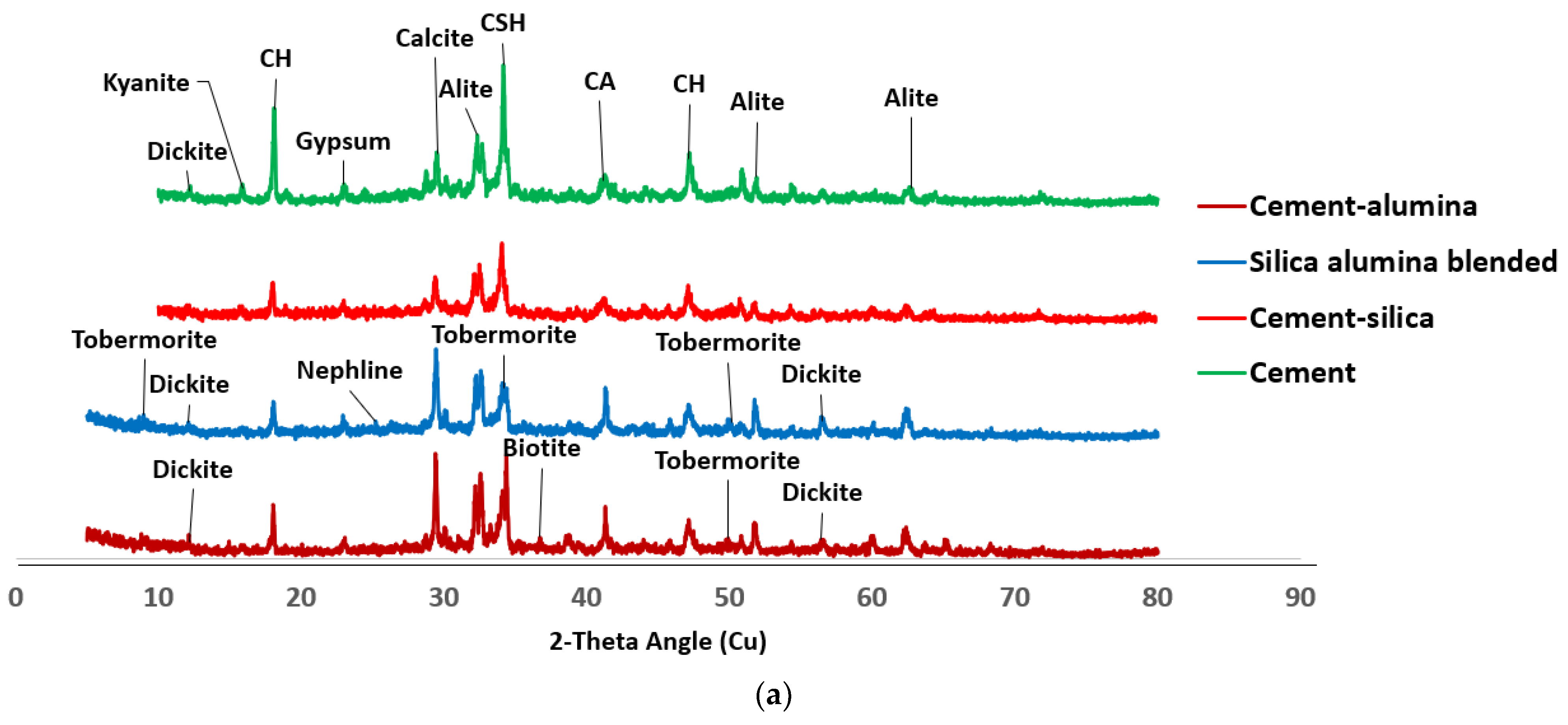
  • The early compressive strength of SF blended mortar (C90S10A0) was lower than that of OPC (C100S0A0), while incorporation of nA significantly enhanced early and 28-d compressive strength; CSH, CASH, tobermorite (CSH of lower Ca/Si ratio), calcite, and mayenite dominated the SF–nA ternary binder phases as noted in the XRD.
  • Introducing nA to the SF blended binder caused a reduction in Ca/Al and Si/Al ratios compared to those in the OPC binder.
  • The calcite peak and CO vibration peak in the XRD and FTIRS indicate that the SF–nA ternary blended binder was more prone to carbonation compared to SF blended concrete due to the possible dual formation of aluminum and calcium carbonates.
  • The optimum microstructural density and maximum 28-day compressive strength of 43.2 MPa were achieved in the 10% SF and 2% nA (C88S10A2) mixture, whereas 36 and 30.5 MPa were recorded in OPC (C100S0A0) and 10% SF blended mortar (C90S10A0), respectively.
  • The SF–nA ternary blended binder (C88S10A2) had the best thermal resistance—with a 3.7% loss of its 28-day strength, which became 8.85 and 33.3% in the SF binary blended binder (C90S10A0) and OPC binder (C100S0A0), respectively.

Funding

This research received no external funding.

Institutional Review Board Statement

Not applicable.

Informed Consent Statement

Not applicable.

Data Availability Statement

Not applicable.

Conflicts of Interest

The author declares no conflict of interest.

References

  1. Quercia, G.; Brouwers, H.J.H. Application of nano-silica (nS) in concrete mixtures. In Proceedings of the 8th Fib PhD Symposium in Kgs, Lyngby, Denmark, 20–23 June 2010; pp. 431–436. [Google Scholar] [CrossRef]
  2. Ghasemi, A.R.; Parhizkar, T.; Ramezanianpour, A.A. Influence of Colloidal Nano-SiO2 Addition as Silica Fume Replacement Material in Properties of Concrete. In Proceedings of the Second International Conference on Sustainable Construction Materials and Technologies, Ancona, Italy, 28–30 June 2010; pp. 28–30. [Google Scholar]
  3. Björnström, J.; Martinelli, A.; Matic, A.; Börjesson, L.; Panas, I. Accelerating effects of colloidal nano-silica for beneficial calcium-silicate-hydrate formation in cement. Chem. Phys. Lett. 2004, 392, 242–248. [Google Scholar] [CrossRef]
  4. Peerzada, M.; Adnan, K.; Bilal, B.; Janees, R.; Qazi, B.; Javed, N.A. Aptness of nano alumina (Al2O3) with high range water reducer-incorporated concrete. World J. Eng. 2023, 20, 746–753. [Google Scholar] [CrossRef]
  5. Orakzai, M.A. Hybrid effect of nano-alumina and nano-titanium dioxide on Mechanical properties of concrete. Case Stud. Constr. Mater. 2021, 14, e00483. [Google Scholar] [CrossRef]
  6. Krishnaveni, C.; Selvan, S.S. Nano-alumina incorporation into concrete by various methods. Mater. Today Proc. 2022, 68, 1926–1929. [Google Scholar] [CrossRef]
  7. Ashok, K.; Rao, B.K.; Kumar, B.S.C. Experimental Investigation on Nano Alumina based Concrete. ARPN J. Eng. Appl. Sci. 2021, 16, 76–87. [Google Scholar]
  8. Sadik, C.; El Amrani, I.; Albizane, A. Recent advances in silica-alumina refractory: A review. J. Asian Ceram. Soc. 2014, 2, 83–96. [Google Scholar] [CrossRef]
  9. Yusuf, M.O. Performance of Aluminium Shaving Waste and Silica fume Blended Mortar. Mag. Civ. Eng. 2023, 122, 12209. [Google Scholar]
  10. Yu, J.; Song, H.; Jeon, D.; Sim, S.; Kim, D.; Lee, H.; Yoon, S.; Yum, W.S.; Oh, J.E. Influence of the degree of crystallinity of added nano-alumina on strength and reaction products of the CaO-activated GGBFS system. Constr. Build. Mater. 2021, 296, 123647. [Google Scholar] [CrossRef]
  11. Prabaharan, J.S.; Sophia, M.; Babu, O.G.; Raja, M.A. High temperature effects on the compressive strength and UPV of nano alumina modified concrete containing sillimanite. Mater. Today Proc. 2022, 62, 5613–5619. [Google Scholar] [CrossRef]
  12. Shao, Q.; Zheng, K.; Zhou, X.; Zhou, J.; Zeng, X. Enhancement of nano-alumina on long-term strength of portland cement and the relation to its influences on compositional and microstructural aspects. Cem. Concr. Compos. 2019, 98, 39–48. [Google Scholar] [CrossRef]
  13. Yu, J.; Sim, S.; Song, H.; Kim, D.; Jang, K.; Jeon, D.; Oh, J.E. Examination of sulfate resistance of nano-alumina added ordinary Portland cement paste, focusing on the two different crystallinity of nano-aluminas. Int. J. Concr. Struct. Mater. 2023, 17, 32. [Google Scholar] [CrossRef]
  14. Dyer, T. Concrete Durability; CRC Press: Boca Raton, FL, USA, 2014. [Google Scholar]
  15. Mehta, P.K.; Klein, A. Formation of ettringite in pastes containing calcium aluminoferrites and gypsum. Highw. Res. Rec. 1967, 192, 32–45. [Google Scholar]
  16. Weather in the Middle East. Available online: http://climateandweather.com/weather-in-middle-east (accessed on 11 September 2023).
  17. Li, Z.; Wang, H.; He, S.; Lu, Y.; Wang, M. Investigations on the preparation and mechanical properties of the nano-alumina reinforced cement composite. Mater. Lett. 2006, 60, 356–359. [Google Scholar] [CrossRef]
  18. Nazari, A.; Riahi, S.; Riahi, S.; Shamekhi, S.F.; Khademno, A. Influence of Al2O3 Nanoparticles on the Compressive Strength and Workability of Blended Concrete. 2010. Available online: http://[email protected] (accessed on 1 August 2023).
  19. Nazari, A.; Riahi, S. The effect of aluminium oxide nanoparticles on the compressive strength and structure of self-compacting concrete. Mag. Concr. Res. 2012, 64, 71–82. [Google Scholar] [CrossRef]
  20. Carmo, R.N.F.; Costa, H.; Júlio, E. Influence of nanoparticles additions on the bond between steel fibres and the binding paste. Constr. Build. Mater. 2017, 151, 312–318. [Google Scholar] [CrossRef]
  21. Krishnaveni, C.; Selvan, S.S. Study on nano-alumina in concrete. Mater. Today Proc. 2020, 46, 3648–3652. [Google Scholar] [CrossRef]
  22. Zhan, B.J.; Xuan, D.X.; Poon, C.S. The effect of nanoalumina on early hydration and mechanical properties of cement pastes. Constr. Build. Mater. 2019, 202, 169–176. [Google Scholar] [CrossRef]
  23. Shabbar, R.; Nedwell, P.; Wu, Z. Mechanical properties of lightweight aerated concrete with different aluminium powder content. MATEC Web Conf. 2017, 120, 02010. [Google Scholar] [CrossRef]
  24. Younus, S.J.; Mosaberpanah, M.A.; Alzeebaree, R. The Performance of Alkali-Activated Self-Compacting Concrete with and without Nano-Alumina. Sustainability 2023, 15, 2811. [Google Scholar] [CrossRef]
  25. ASTM C157; Standard Test Method for Length Change of Hardened Hydraulic-Cement Mortar and Concrete. America Standard Method of Testing: West Conshohocken, PA, USA, 2008.
  26. ASTM C191-21; Standard Test Methods for Time of Setting of Hydraulic Cement by Vicat Needle. America Standard Method of Testing: West Conshohocken, PA, USA, 2021.
  27. ASTM C1437-20; Standard Test Method for Flow of Hydraulic Cement Mortar. America Standard Method of Testing: West Conshohocken, PA, USA, 2020.
  28. ASTM C109/C109M-20; Standard Test Method for Compressive Strength of Hydraulic Cement Mortars (Using 2-in. or [50-mm] Cube Specimens). America Standard Method of Testing: West Conshohocken, PA, USA, 2020.
  29. Yusuf, M.O. Bond Characterization in Cementitious Material Binders Using Fourier-Transform Infrared Spectroscopy. Appl. Sci. 2023, 13, 3353. [Google Scholar] [CrossRef]
  30. Zhou, J.; Zheng, K.; Liu, Z.; He, F. Chemical effect of nano-alumina on early-age hydration of Portland cement. Cem. Concr. Res. 2019, 116, 159–167. [Google Scholar] [CrossRef]
  31. Zahedi, R.; Mirmohammadi, S.J. Sulfate removal from chemical industries’ wastewater using ettringite precipitation process with recovery of Al(OH)3. Appl. Water Sci. 2022, 12, 226. [Google Scholar] [CrossRef]
  32. Lecomte, I.; Henrist, C.; Liégeois, M.; Maseri, F.; Rulmont, A.; Cloots, R. (Micro)-structural comparison between geopolymers, alkali-activated slag cement and Portland cement. J. Eur. Ceram. Soc. 2006, 26, 3789–3797. [Google Scholar] [CrossRef]
Figure 1. Nano alumina and silica fume.
Sustainability 15 14615 g001
Figure 2. XRD diffractograms of cement (top), silica fume (middle), and nano alumina (bottom).
Sustainability 15 14615 g002
Figure 3. Consistency of silica fume with alumina in OPC blended mortar.
Sustainability 15 14615 g003
Figure 4. Setting time of silica fume alumina blended mortar.
Sustainability 15 14615 g004
Figure 5. Effect of silica fume addition to OPC mortar.
Sustainability 15 14615 g005
Figure 6. (a) XRD diffractogram of OPC, OPC-nA, OPC-SF bended, and OPC-SF–nA blended paste. (b) XRD diffractogram of SF-OPC blended and SF–nA-OPC blended pastes.
Sustainability 15 14615 g006aSustainability 15 14615 g006b
Figure 7. Morphology and EDS of OPC, SF binary, and SF–nA ternary blended mortar.
Sustainability 15 14615 g007
Figure 8. Morphology of samples containing OPC only, OPC + alumina, and OPC + alumina + silica.
Sustainability 15 14615 g008
Figure 9. FTIR of the SF-OPC and SF–nA-OPC blended pastes.
Sustainability 15 14615 g009
Figure 10. Thermal performance of SF binary and SF–nA ternary mortar.
Sustainability 15 14615 g010
Table 1. Oxide compositions of the raw materials.
Oxide CompositionOPCSFNano Alumina
SiO219.0195.850.00
Al2O34.680.2699.87
Fe2O33.200.050.03
CaO66.890.210.07
MgO0.810.450.03
Na2O0.090.4-
TiO20.22--
K2O1.171.22-
P2O50.08--
SO33.661.00-
MnO0.190.00-
SiO2 + Al2O3 + Fe2O326.8996.1699.90
SG3.142.253.38
LOI (%)2.802.481.05
Surface area (m2/g)0.3322.8440
Table 2. Mixture proportion of alumina blended mortar.
SamplesCement (Kg/m3)Silica Fume (Kg/m3)Alumina (Kg/m3)Sand (Kg/m3)Water (Kg/m3)SP (Kg/m3)Wet Density
C100S0A0350.000.000.001809.84157.503.502320.84
C90S10A0315.0035.000.001798.64157.503.502309.64
C89S10A1311.5035.003.501798.84157.503.502309.84
C88S10A2308.0035.007.001799.04157.503.502310.04
C87S10A3304.5035.0010.501799.24157.503.502310.24
Table 3. Elemental composition of different microstructures.
ElementOPCSF + OPCSF + OPC + nAOPC + nA
C8.815.111.115.5
O49.944.644.244.6
Al1.041.41.61.7
Si6.410.88.29.7
K1.601.60
Ca30.826.532.227.1
Fe1.11.72.11.5
Ca/Si4.82.53.92.8
Ca/Al29.618.920.115.9
Si/Al6.27.75.15.7
Disclaimer/Publisher’s Note: The statements, opinions and data contained in all publications are solely those of the individual author(s) and contributor(s) and not of MDPI and/or the editor(s). MDPI and/or the editor(s) disclaim responsibility for any injury to people or property resulting from any ideas, methods, instructions or products referred to in the content.

