Article

A Case Study Integrating Numerical Simulation and InSAR Monitoring to Analyze Bedding-Controlled Landslide in Nanfen Open-Pit Mine

1
Key Laboratory of Ministry of Education on Safe Mining of Deep Metal Mines, Northeastern University, Shenyang 110819, China
2
Center for Rock Instability and Seismicity Research, Northeastern University, Shenyang 110819, China
*
Authors to whom correspondence should be addressed.
Sustainability 2023, 15(14), 11158; https://doi.org/10.3390/su151411158
Submission received: 5 June 2023 / Revised: 2 July 2023 / Accepted: 12 July 2023 / Published: 18 July 2023

Abstract

:
Bedding-controlled landslides are a common geological hazard for open-pit metal mines and occur on layered rock slopes. It can spread spatially over the final boundary of the dip slope and persist throughout the entire life cycle of the mine, substantially compromising the safety of mining operations. Identifying potential landslide areas and determining the landslide mechanism is crucial for the safety production and slope management of mines. This study proposes a combination of satellite radar interferometry measurement and numerical simulation to determine the landslide mechanism of the bedding-controlled slope in open-pit mines. First, the multidimensional small baseline subset (MSBAS) technique of interferometric synthetic aperture radar (InSAR) is used to capture deformation information in the vertical and east–west directions of the slope, locate large-scale and long-term movements, and preliminarily determine the trend of landslides. Then, a layered slope damage constitutive model is established, and a three-dimensional stability calculation of the layered slope is performed using COMSOL Multiphysics 5.3 software based on the strength reduction method to study the development and evolution process of landslides. The effectiveness of the method is validated by a large-scale bedding-controlled slope failure in the Nanfen open-pit mine in Liaoning, China, revealing the failure mechanism of the slope under excavation conditions. The study shows that the eastern slope bedding-controlled landslide in the Nanfen open-pit mine is a multizone composite-mode landslide caused by excavation, which belongs to the shear–slip–tension deformation failure mechanism as a whole. This study provides a new method for analyzing the mechanism of layered rock slope landslides under mining activities in open-pit mines, which can be used to assess and predict similar landslides.

1. Introduction

In open-pit metal mines, the stability of rock slopes is a critical factor in ensuring the safety and productivity of mining operations. There are many layered rock slopes in open-pit mines. The occurrence of bedding-controlled rock slope landslides, which can cause significant damage to infrastructure, equipment, and personnel, is one of the major problems that mining engineers must manage [1]. The landslide occurrence in an open-pit mine is influenced not only by internal factors such as geological structure, rock mass properties, and groundwater, but also by external factors such as rainfall, excavation, and blasting vibration [2,3]. The complex factors make it difficult to determine the potential landslide scope and analyze the landslide mechanism.
The monitoring of high and steep slope deformation in open-pit mines is usually carried out by means of field measurement methods such as total stations, GPS, GNSS, crack meters, etc. Low efficiency, high cost, and a small monitoring range are some of the disadvantages of these traditional monitoring methods. In contrast, satellite-based synthetic aperture radar (SAR) interferometry provides an effective tool for landslide deformation monitoring from regional to local scales [4,5]. InSAR, a new ground surface deformation measurement method, can now obtain ground surface deformation information over a large area with the help of the continuous development of SAR satellites and data processing technologies. It has been widely used to monitor surface subsidence [6], landslides [7], seismic activities [8], slope deformation caused by open-pit mining activities [9,10], and other activities. All-weather earth observation, low cost, and high efficiency are some of its advantages [11]. Although conventional InSAR technology has made great progress in monitoring ground surface deformation, the accuracy of monitoring results is affected to some extent due to many factors such as atmospheric delay and a loss of temporal coherence, limiting InSAR monitoring deformation.
Time-series InSAR has been developed as an extension of conventional InSAR technology to obtain high-precision ground surface deformation information and long-term evolution characteristics of ground targets. This technology enables the large-area and high-precision measurement of ground surface deformation by analyzing the time series of multi-scene SAR data. Commonly used time-series InSAR techniques include stacking-InSAR [12], permanent scatterer (PS-InSAR) [13], small baseline subset (SBAS-InSAR) [14], etc. However, the side-looking imaging characteristics of the radar can only capture one-dimensional deformation in the line-of-sight direction. For open-pit slope deformation, one-dimensional deformation in the radar’s line-of-sight direction does not fully reflect the characteristics of ground surface deformation, necessitating horizontal deformation analysis. SAR image data covering the same area from different orbits can not only be used to verify the accuracy of SAR data monitoring results, but also provide basic data to obtain two-dimensional deformation information in the study area. Due to satellite orbit flight tracks being almost parallel to the longitude line and close to the north–south direction, InSAR technology is not particularly sensitive to monitoring north–south ground surface deformation. To overcome this limitation, this study applied the multidimensional small baseline subset (MSBAS) technique [15] to calculate the two-dimensional deformation time series of both ascending and descending orbit SAR data covering the study area. Specifically, this technique estimated the time series of deformation in both the vertical and east–west directions.
Through InSAR monitoring, it is possible to capture the scope of landslides in advance, and based on the detected displacement changes, it is possible to make a preliminary judgment on the trend of landslides. After delineating the approximate scope of the landslide, numerical simulation can be used to simulate the evolution process and failure mechanism of the landslide. Compared with surface deformation measured by InSAR, numerical simulation can model the full-range movement process, mechanical response, and evolution law of landslides. Numerical calculation methods mainly include continuous analysis methods [16,17] (such as the finite difference method, the finite element method, the boundary element method, the meshless method, etc.), discontinuous deformation analysis methods [18,19] (such as discontinuous deformation analysis, the discrete element method, the manifold element method, etc.), and the hybrid finite–discrete element method [20,21]. Discontinuous medium methods are excellent in simulating the failure and evolution processes of layered rock masses. The discontinuous medium method has the disadvantages of complex numerical modeling and a large computational load for the engineering problems of layered rock masses studied in this paper. The continuous analysis method is currently the most suitable choice for research. Numerical modeling combined with InSAR has been used to derive the deformation of dams [22] and urbanized hillslopes [23]. However, the coupling of InSAR and numerical simulation methods has been less studied in the analysis of slope landslide mechanisms in open-pit mines, especially for bedding-controlled rock slopes. This study proposes a method combining satellite InSAR and numerical simulation to analyze the landslide mechanism of bedding-controlled open-pit mine slopes. The proposed approach is applied to the Nanfen open-pit mine, Liaoning Province, China. InSAR monitoring can capture surface displacement changes of the open-pit slope, delineate potential landslide areas, and make preliminary judgments on landslide trends. Based on this, numerical modeling is conducted on the delineated area, and a damage constitutive model for layered slopes is established to perform a more detailed analysis of the slope failure mechanism. The combination of these two methods has improved the numerical computation efficiency and the accuracy of research results.

2. Study Area

The study area is located in Nanfen district, Benxi City, Liaoning Province, China, which is situated in the eastern mountainous area of Liaoning Province. It is 25 km away from the downtown of Benxi City and about 108 km away from the provincial capital of Liaoning Province, Shenyang. The Anshan-Benxi area is the main distribution area of China’s banded iron-formation-type iron deposits (Anshan-type iron deposits), and the proven resource reserves account for about 40% of the total proven resource reserves of similar iron deposits in China. It is the largest iron ore resource base in China [24].

2.1. Engineering Geology

The Nanfen open-pit mining area (123°47′42″ E–123°49′26″ E, 41°4′54″ N–41°6′19″ N) has a developed geological structure because of its location at the intersection of the Tianshan-Yinshan east–west tectonic belt and the second uplift belt of the Neocathaysian system. The main structures are overturned anticlines and NNE-trending major faults. The mining area is located in the northern margin of the Taizihe depression, which is situated in the Yingkou–Kuandian upwarp of the Liaodong anticline on the North China platform. The area is extensively developed with Archean Anshan formation, followed by Paleoproterozoic Liaohe group and Sinian strata, as well as Neogene Quaternary strata. The mining area is located in a temperate and humid climate zone, with an average annual temperature of 6.1 °C–7.8 °C, and a relatively abundant precipitation of about 880 mm annually, with a maximum daily precipitation of 274 mm. Rainfall is concentrated from April to September, which accounts for about 85% of the total annual precipitation.

2.2. Mining Conditions

The Nanfen open-pit mine is a large open-pit iron mine with an annual production capacity of 10 million tons. The open pit spans a 4.6 km2 area and is 5.5 km in length from north to south, 0.4–1 km in width from east to west. According to Figure 1, the maximum elevation difference of the slope is approximately 590 m.
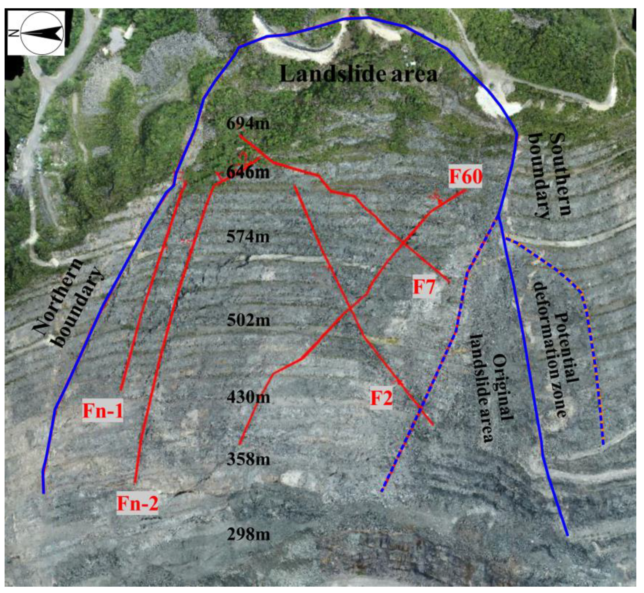
A bedding rock slope, with a slope angle of 34.17°, a bottom elevation of 190 m, and a top elevation of 694 m, makes up the eastern slope of the Nanfen open-pit mine. Due to the unique terrain and long-term mining, a large-scale landslide mass was formed on the eastern slope in 1999. On 19 June 2021, a landslide occurred on the eastern slope (hereinafter referred to as the 6.19 landslide) with a height of nearly 410 m (from the top of the slope at 710 m to the toe of the slope at 298 m levels), a thickness of about 30–80 m, 480 m wide in the upper part, and 1200 m wide in the lower part. The shear entry point of the landslide is about 70 m behind the rear edge of the 694 m berm, while the shear exit point is located on the 298 m berm. The slope surface was overrun by rolling stones, and the sliding mass was accompanied by the sound of the dislocation of rocks. The uplift height of the 298 m berm was 1–2 m, and the 694 m, 574 m, and 502 m berms had all dropped by 5 m, 3 m, and 1.5 m, respectively. Field investigations revealed that the mica schist, chlorite schist, epidote amphibolite, iron ore, two-mica quartz schist, quartz granulite, granite, etc., are the primary types of rocks in the landslide area. The faults affecting the landslide include F60, F7, F2, Fn-1, and Fn-2 (as shown in Figure 2), and their main characteristics are described in Table 1.

3. Methodology

The method proposed in this study combines field investigations, remote sensing monitoring, and numerical simulations to analyze the landslide mechanism of the bedding-controlled slope in open-pit mines. First, the MSBAS-InSAR technique was used to capture the surface displacements of the slope in both vertical and horizontal directions at a large scale, and to make preliminary judgments on the trend of the landslide. Then, a numerical calculation model was established using geological cross-sections and unmanned aerial vehicle (UAV) tilt photography data. Moreover, to evaluate the slope stability and infer the bedding failure process of the slope, multiple three-dimensional numerical simulations in COMSOL Multiphysics software were conducted using the damage constitutive model of the layered slope.

3.1. Monitoring with InSAR

This study employed the multidimensional small baseline subset (MSBAS) technique proposed by Samsonov [15] to compute the two-dimensional deformation time series of the ascending and descending track SAR data over the study area, i.e., estimating the deformation time series in the vertical and east–west directions. This method is used to integrate multiple InSAR datasets for computing two-dimensional or three-dimensional deformation time series. The method allows the combination of all possible air-borne and space-borne SAR data acquired with different acquisition parameters, temporal and spatial sampling and resolution, wave-band, and polarization. The produced time-series have improved temporal resolution and can be enhanced by applying either regularization or temporal filtering to remove high-frequency noise. The basic principle of the MSBAS technique can be found in reference [15].
Sentinel SAR data were utilized in this paper. Within the European Space Agency’s Copernicus program, the Sentinel satellite is an Earth observation satellite with an all-weather, all-day radar imaging system [25]. We processed repeat orbit SAR images from 31 ascending and 29 descending passes acquired between September 2020 and August 2021 to investigate the deformation of the eastern slope of the Nanfen open-pit mine. This allowed us to determine the spatial and temporal distribution and evolution characteristics of ground surface deformation in the study area.

3.2. Numerical Modeling

3.2.1. Numerical Calculation Model

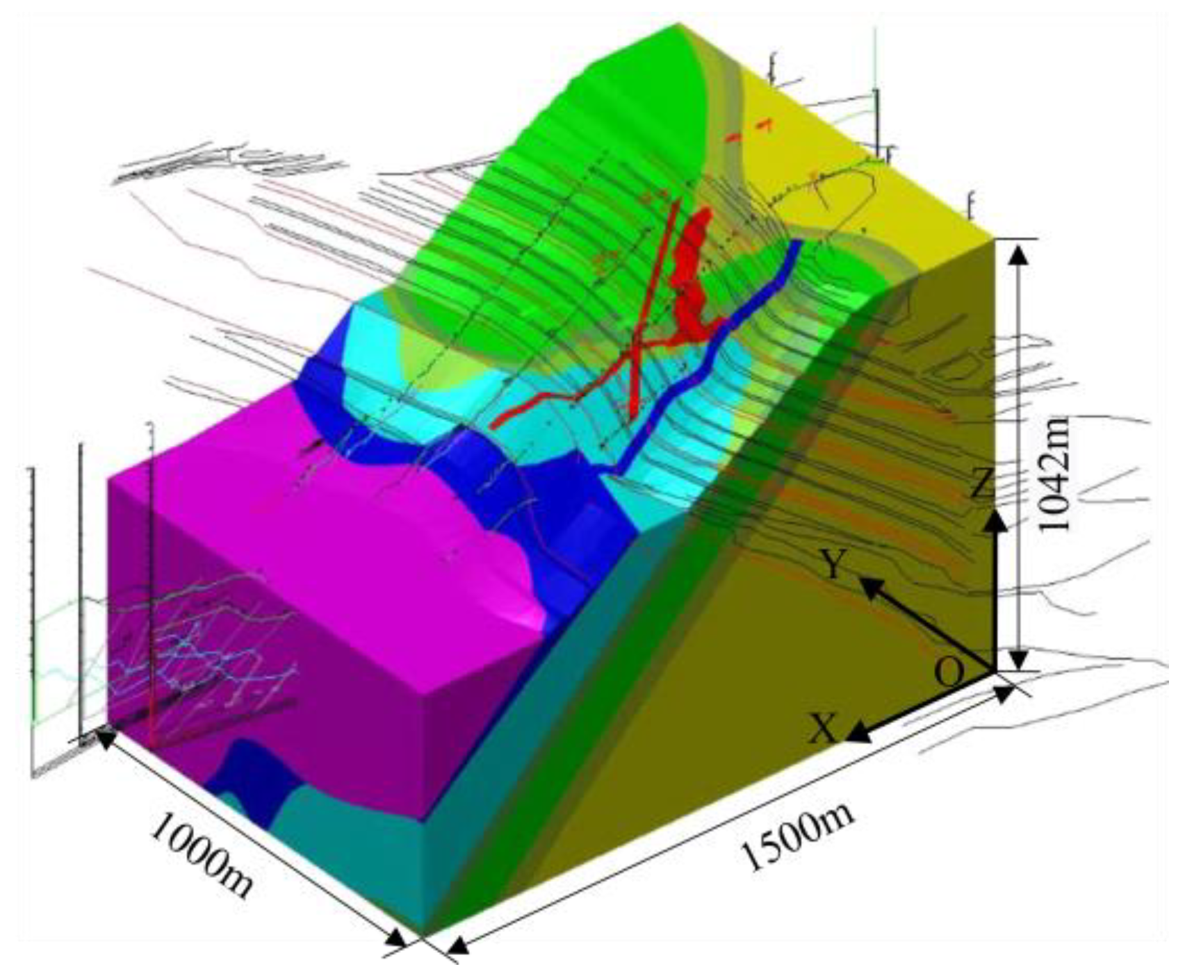
Slope surfaces from various time periods were extracted using UAV tilt photogrammetry technology in April 2019 and July 2021. Software called 3D Mine 2014 was used to design the three-dimensional contour lines of cleaning and safety berms. Through coordinate transformation, three typical geological profiles of the landslide area were transformed into three-dimensional geological profiles. Rhino software 6.0 was used to import the main bench lines and geological boundary lines once they had been simplified. A multi-surface of slope surface and the lithologic interface was established by lofting and sweep operations of multi-segment lines. Finally, Boolean operations were used to construct the geometric solid model (Figure 3). The model measures 1500 m in length, 1000 m in width, and 1042 m in height.
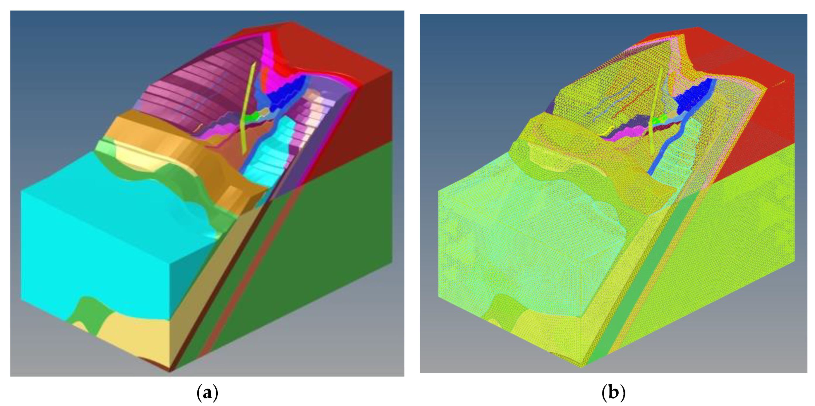
For mesh division, the constructed geometric model was imported into COMSOL Multiphysics 5.3. The geometric model was divided into 42 independent areas (Figure 4a). The surface of the model was divided into 2D grids that were 15 m long triangular grids. The interior of the geometric model is then divided into regular tetrahedral grids. A total of 1,061,182 grids from the entire geometric model (Figure 4b) were imported into COMSOL Multiphysics.
The fixed constraint was applied at the bottom, the normal displacement constraint was applied around the geometric model, and the rest of the area was a free boundary. In this analysis, the force of gravity served as the only load on the slope. The influence of excavation (i.e., 298 m–374 m mining area of eastern slope) on slope stability was considered in the numerical simulation process.
Laboratory experiments were conducted on the mechanical parameters of the rock mass, including uniaxial compression, Brazilian splitting, and direct shear tests, to determine the strength parameters of the rock strata. Due to the complex geological conditions in the mining area, there are many natural joints and fractures, and the mechanical properties of the in situ rock mass may be lower than those measured in the laboratory. Therefore, the Hoek–Brown failure criterion [26] was used to evaluate the mechanical properties of the rock mass in this paper. Table 2 shows the mechanical parameters used in the numerical calculations.

3.2.2. Damage Constitutive Model of Layered Slope

In this paper, the progressive failure process of the layered slope was investigated using elastic damage mechanics [27]. Based on the fundamental assumption of isotropy of the rock microstructure and the Lemaitre strain equivalence principle [28], and assuming that the constitutive relationship follows Hooke’s law, the elastic damage constitutive model can be expressed as Equation (1):
σ i j = 1 D E ε k l
where D is the damage variable, E is the elastic stiffness matrix, and σ i j and ε k l are the stress and strain components, respectively. The damage variable evolution equation refers to RFPA [29], as shown in Equation (2):
D = 0 F 1 0 , F 2 0 1 ε t 0 k t n F 1 > 0 , ε t 0 < k t 1 ε c 0 k c n F 1 0 , F 2 > 0 , ε c 0 < k c
where the respective limit strains for the tensile and compressive forces are ε t 0 and ε c 0 . The maximum tensile strain and maximum compressive strain are recorded with state variables k t and k c , respectively, due to the irreversibility of damage. F 1 and F 2 represent the tensile strength criterion and compressive strength criterion, respectively. n is the empirical coefficient; n = 2 [29]. The specific calculation formulas [29] are Equations (3)–(10):
ε t 0 = σ c ¯ / c E ¯
ε c 0 = σ c _ min / E ¯
k t = max ε e f t , ε e f t _ hist
k c = max ε e f c , ε e f c _ hist
ε e f t = ε 1 2 + ε 2 2 + ε 3 2
ε e f c = max 0 , ε 3
F 1 = σ c / c σ 1
F 2 = σ 3 + σ 1 1 + sin ϕ 1 sin ϕ σ c
where σ c ¯ and E ¯ are the average uniaxial compressive strength (UCS) and the average elastic modulus, respectively. σ c _ min is the minimum UCS. C is the average ratio of tensile and compressive strength. The equivalent tensile and compressive strains are ε e f t and ε e f c , respectively. ε e f t _ hist and ε e f c _ hist are used to record the historical maximum equivalent tensile and compressive strains, respectively. ε 1 , ε 2 , and ε 3 are the maximum principal strain, the intermediate principal strain, and strain minimum principal strain, respectively.   is Macaulay bracket (replaced by zero in negative values). σ 1 and σ 3 are the maximum principal stress and the minimum principal stress, respectively.
The maximum value of the damage variable in this paper was 0.99 in order to ensure the convergence of the finite element calculation program and consider the residual strength of the slope rock mass. Based on COMSOL Multiphysics’ finite element solid mechanics module, we developed a damage mechanics model suitable for layered rock mass by using COMSOL with MATLAB functions. The mechanical parameters and state variables in the iterative calculation of damage were written out in text form. It was then entered as a loop variable in the form of an interpolating file. Tensile strain was positive, while compressive strain was negative. The aforementioned elastic damage constitutive model was combined with the slope strength reduction method. This paper adopts the slope strength reduction method and refers to the strength reduction method used in RFPA-SRM proposed by Tang [30]. The tensile strength σ t and uniaxial compressive strength σ c of the rock mass are uniformly reduced at a certain step length, and the strength reduction is accompanied by a corresponding test safety factor F s t r a i l . When significant failure deformation trends such as maximum tensile strain k t and maximum compressive strain k c appear, the slope becomes unstable, and the safety factor at this point is the final safety factor F o s (Equations (11) and (12)):
F o s = c c ' = tan ϕ tan ϕ '
σ c t r a i l = σ c 0 / F s t r a i l σ t t r a i l = σ t 0 / F s t r a i l
where c and c ' represent the cohesion before and after reduction, respectively. ϕ and ϕ ' represent the friction angle before and after reduction, respectively.

4. Results

4.1. Validation with Monitoring Results

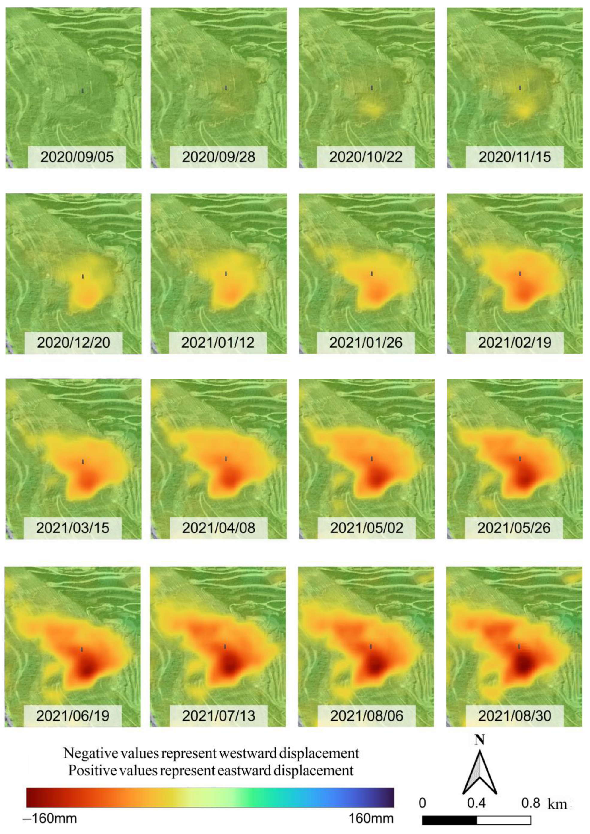
The SAR image data of the study area were processed to produce the temporal and spatial evolution characteristics of the deformation of the eastern slope of the Nanfen open-pit mine. Figure 5 (where the red area represents the downward displacement, and the blue area represents the upward displacement) and Figure 6 (where the red area represents the westward displacement, and the blue area represents the eastward displacement), respectively, show the cumulative displacement in the vertical and east–west directions. The vertical and east–west displacement of the monitoring area can be seen to change significantly with time. The maximum settlement value of the slope was 100 mm by August 2021, while the maximum displacement value toward the west (interior of the mining pit) was 160 mm.
From Figure 5, it can be seen that the vertical downward displacement of the eastern slope began to appear in September 2020, and by November 2020, the range and displacement of the slope subsidence had slowly increased. From December 2020 to May 2021, the range of slope subsidence accelerated to the north and upward, and the displacement in some areas also accelerated. The areas with the largest cumulative subsidence are concentrated in the southern and central parts of the monitoring area, and as time progresses, the subsidence area continues to expand to the north and upward. At the same time, an upward displacement appeared at the bottom of the monitoring area, indicating that the slope in this area had uplifted. From June to August 2021, the cumulative subsidence of the slope slowly increased, and the subsidence range remained ultimately unchanged. From Figure 6, it can be seen that the trend of change in the cumulative horizontal displacement and range is basically consistent with the trend of change monitored in the vertical direction. It can be clearly seen that the slope moves westward (inside the mine), and the area where movement occurs gradually expands to the north and upward. Moreover, the rate of movement first slowly increases, then accelerates, and finally slowly increases again.
According to the InSAR monitoring results, the slope experienced a long period of movement before the occurrence of the 6.19 landslide, which provided conditions for the advanced rapid identification of the landslide. In May 2021, the range of the landslide (sliding mass) had essentially been determined, and the development trend and scope of the landslide could be preliminarily determined. By focusing on this area for slope stability, the numerical simulation calculations can not only reduce the amount of calculations, but also accurately analyze the slope failure mechanism.

4.2. Numerical Simulation Analysis Results

(1)
Before the mining of 298 m–374 m berm
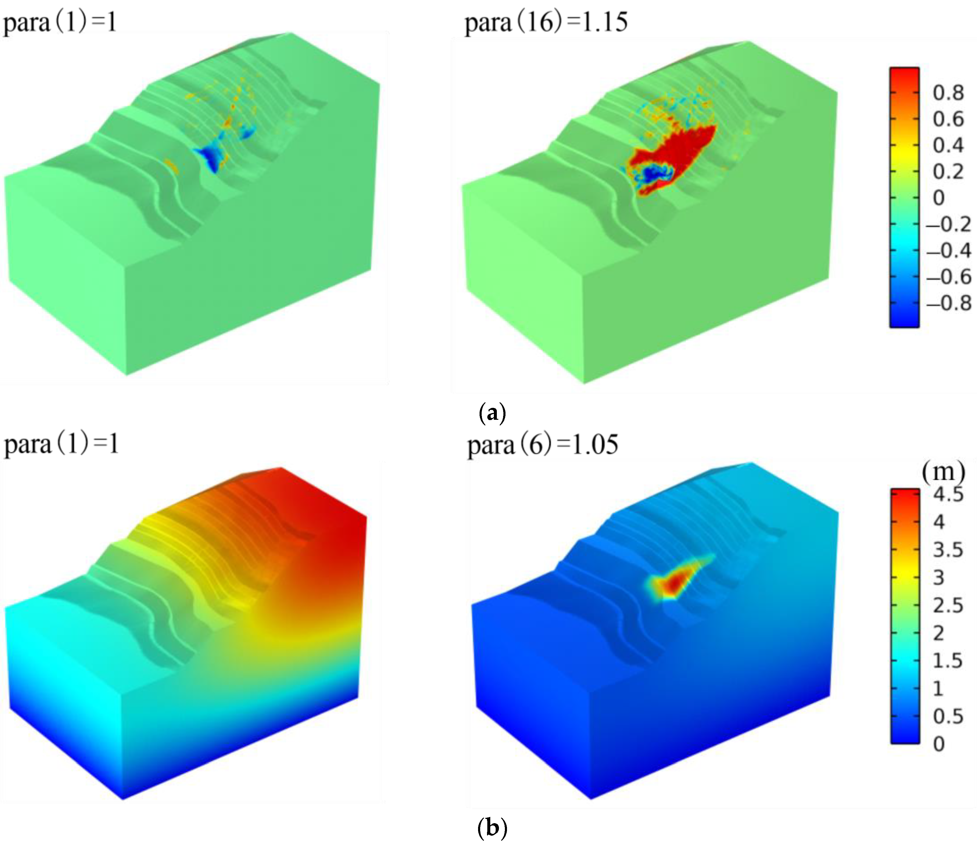
The original landslide body was undergoing a progressive sliding process prior to mining the 298 m to 374 m berm. The quality of the rock mass continuously deteriorated during mining operations because of the presence of multiple structures controlling the landslide mass. The resulting progressive sliding and disintegration of the landslide mass led to the formation of a loose accumulation body (Figure 7).
(2)
After the mining of 298 m–374 m berm
The original landslide area had already formed prior to the occurrence of the 6.19 landslide, providing an early southeastern free face for the new and larger-scale sliding, particularly for the sliding mass of the 6.19 landslide. Therefore, using the pre-excavation damage field in the numerical simulation calculations following excavation is compatible with the actual situation.
The slope toe was no longer a constraining factor with the excavation of 298 m to 374 m berm. Additionally, the blasting vibration during the mining process activated the faults in the area to varying degrees. Therefore, it was reasonable to decrease the relevant rock mass mechanical parameters to a certain extent during the simulation process. The simulation results indicated that, the macroscopic mechanism of sliding body was the accumulative damage of the original landslide area, which induced the structural activation of faults and fracture zones on the north side, leading to the continuous expansion of the damaged area to the north and upward, and the formation of several tensile fractures on the north side. Moreover, the 298 m berm has an obvious compression–shear damage area (blue area), which corresponds to the phenomenon of uplift at the toe of the real slope (as shown in Figure 8).
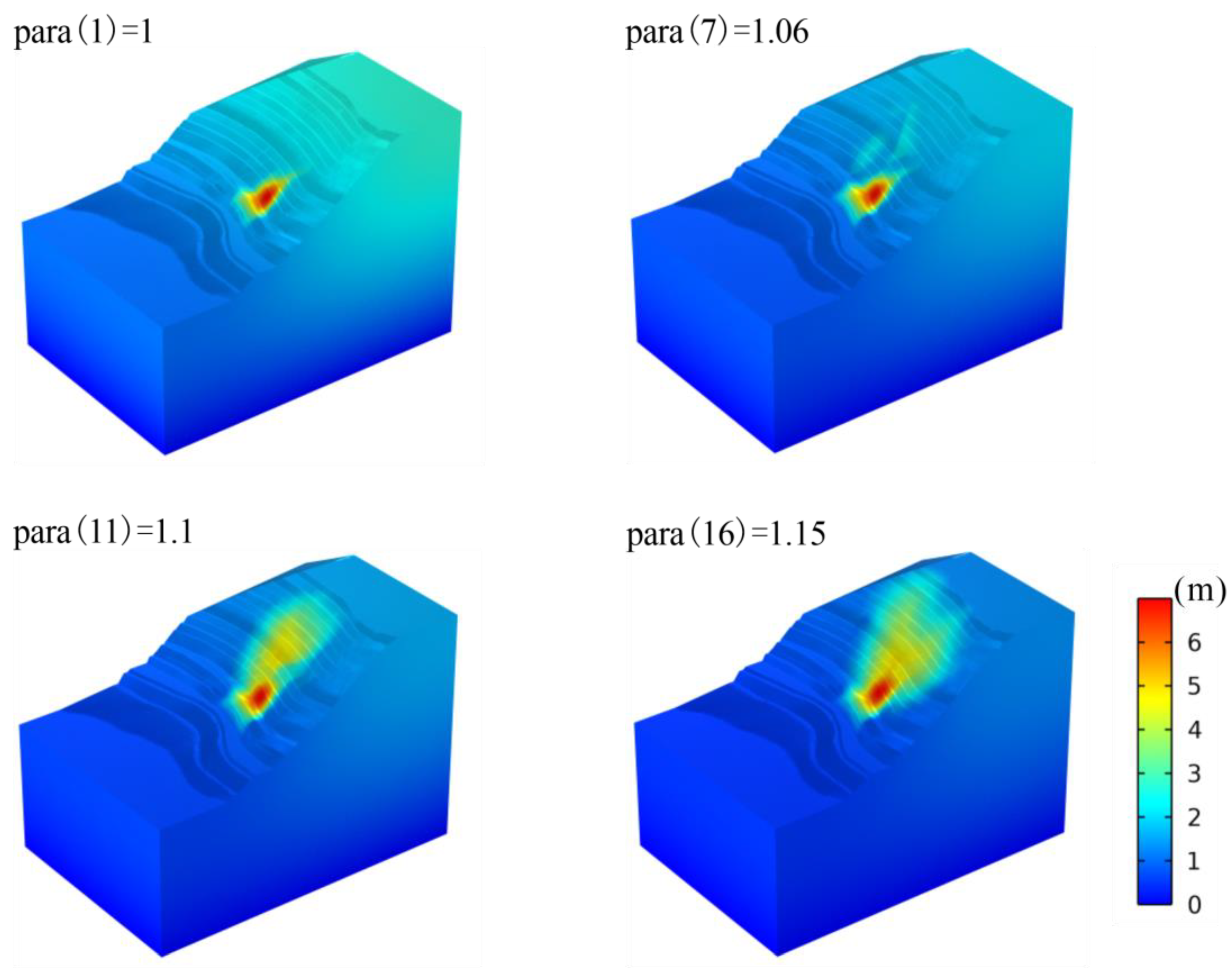
The displacement field of the slope obtained by numerical simulation was slightly smaller than the damaged area, and the deformation area was located within the actual landslide area. Although the magnitude of the sliding displacement was lower than the actual value, the evolution of the displacement field was somewhat synchronized with that of the damaged area, which was consistent with the observed displacement field. This was mainly due to the damage constitutive model used in this study. The range of damage variables was restricted to ensure computational convergence (as shown in Figure 9).
The evolution law of the maximum equivalent tensile strain field obtained by numerical simulation had a good correlation with the crack distribution and fragmentation degree of the rock mass in the slope. As shown in Figure 10, the disintegration degree of the southern original sliding mass and the northern tensile fracture zone was high, and their integrity was poor, while the integrity of the central sliding mass was relatively better.

5. Discussion

5.1. Landslide Mechanism of Nanfen Open-Pit Mine

The bedding-controlled landslide on the eastern slope of the Nanfen open-pit mine occurred during the mining process on the 298–310 m level. From the InSAR monitoring results and numerical simulation results, it can be determined that the mechanism of the landslide is as follows: (1) unloading due to excavation on the 298–310 m level and (2) the relaxation of rock stress caused by the sustained deformation of the original landslide, leading to tensile failure. This deformation feature confirms that the tensile force of the original landslide on the south side is the key mechanism of this landslide, and its movement direction exhibits a process from north to south to a certain extent. Faults and bedding planes in the rock mass play an important controlling role in the deformation and rupture of the slope.
Through field investigations, it was found that the eastern slope landslide of the open-pit mine is a multizone composite-mode landslide, which belongs to the shear–slip–tension deformation failure mechanism as a whole. Firstly, the rock mass of the original landslide is blocky in structure, and the past landslide events mostly occurred at the intersection of faults and structural planes, causing shear failure. Then, the stress state of other areas connected to the original landslide changes, i.e., stress unloading, which drives the surrounding rock mass to slide along the dominant structural plane toward the direction of the original landslide. At the same time, under the influence of self-weight stress, the slope rock mass moves along the dominant plane and forms a tension zone at the back edge of the sliding body, resulting in back edge tension failure. With the continuous downward movement of the sliding body, the back edge tension failure gradually develops downward, and the boundary of the sliding body gradually expands backward. The displacement of the upper and lower parts of the sliding body is not uniform, resulting in shear compression deformation failure and a bulging phenomenon on the slope surface. Through artificial investigation below the 298 m platform, it was found that the rock mass in this area is relatively intact, and no signs of shear failure were found. It can be speculated that the rock strata here blocked the sliding body from continuing to slide downward, thereby forming the uplift phenomenon of the 298 m berm, and finally forming the current shear outlet of the sliding body.
Figure 11 shows the evolution of the eastern slope landslide, as determined by a combination of field investigations and historical data queries from the mine. (a) As the height of the eastern slope increased, the strength of the bedding rock mass approached its limit, resulting in the formation of the original landslide. (b) As a result of the instability of the original landslide, a free surface was formed on the lower side of the southern part of Zone I, which caused the slope in Zone I to deform downward. (c) As the slope deformation in Zone I continued to expand northward, slope instability developed in Zone II. (d) The slope in Zone II continued to deform northward, causing the slope in Zone III to dislocate and settle and develop large-scale longitudinal tensile cracks. (e) The rock mass in Zone IV slid downward under traction force after the slopes in Zones I, II, and III moved downward, whereas the rock mass in Zone V was affected by upper pressure, causing an uplift of the toe of the slope under shear force. The slope underwent overall settlement, and the area of the landslide had a connected sliding surface. It can be seen that the results of field investigations are in good agreement with the InSAR monitoring results and numerical simulation results. This proves that the method proposed in this paper of combining InSAR monitoring and numerical simulation to determine the bedding-controlled landslide mechanism in open-pit mines is feasible.

5.2. Limitations and Future Work

In this study, the displacement observed by InSAR has an error in the order of magnitude, which is due to the continuous mining of ore in the mine, resulting in the constantly changing boundary of the slope and making it difficult to detect high-density and high-quality target points. Additionally, the atmospheric delay caused by the complex terrain of the mine is difficult to eliminate [31]. The deformation error caused by residual phase can cover some deformation areas with smaller or inconsistent deformation variables, resulting in a decrease in the accuracy of landslide identification [32]. These factors hinder the inversion of InSAR deformation results. At the same time, the influence of water on the occurrence and evolution of landslides was not considered in the numerical simulation analysis in this study, which is our next research task. However, the results show that although there is an error in the order of magnitude of the displacement observed by InSAR, the overall trend of the slope displacement development is reliable. There is good coupling between InSAR and numerical simulation, and the method proposed in this paper can effectively analyze the sliding mechanism of bedding-controlled slopes in open-pit mines.

6. Conclusions

This study proposed a method to determine the bedding-controlled sliding mechanism of open-pit mine landslides by combining satellite radar interferometry measurement with numerical simulation. The method was successfully applied to the prediction of the sliding body range and the analysis of the landslide mechanism on the eastern slope of a Nanfen open-pit mine. The method involves firstly using MSBAS-InSAR technique to capture slope deformation information, locate the extent of the landslide, and make a preliminary determination of the landslide trend. Then, based on the established layered slope damage constitutive model, the slope stability is three-dimensionally calculated using the strength reduction method in COMSOL Multiphysics software to determine the evolution mechanism of the landslide.
Using the MSBAS-InSAR method, the displacement and range change trend of the sliding body on the eastern slope of a Nanfen open-pit mine were determined on a large scale. The sliding body moved downward and westward (inside the pit), and an uplift phenomenon appeared on the 298 m berm. The moving area gradually developed upward and northward. Furthermore, the moving rate can be divided into three stages: slow increase, accelerated increase, and slow increase again. Through numerical calculation, it was found that before the mining of the 298 m–374 m level, the original sliding body was in a creeping process. After the mining of this level, the original sliding body lost its restraining effect, which activated the north-side faults, structural surfaces. The landslide area continued to expand northward and upward, and a significant compression and shear damage zone appeared on the 298 m berm.
The field investigation showed that the eastern slope bedding-controlled landslide in a Nanfen open-pit mine was a multizone composite-mode landslide caused by excavation, which belongs to the shear–slip–tension deformation failure type as a whole. After the excavation of the 298 m–310 m berm, the original sliding body began to disintegrate and slide, which then caused the northern and upper rock masses to slide one after another, and an uplift phenomenon was observed on the 298 m berm. The slope failure mechanism is in good agreement with the InSAR monitoring results and numerical simulation results, which proves that the method proposed in this paper can be used to analyze the sliding mechanism of bedding-controlled slopes in open-pit mines.

Author Contributions

Writing—original draft preparation, D.S.; methodology and validation, D.S., W.D. and T.Y.; writing—review and editing, J.L. and Y.Z. All authors have read and agreed to the published version of the manuscript.

Funding

This research was funded by the National Natural Science Foundation of China (Grant No. U1903216 and 52004052) and the State Key Research and Development Program of China (Grant No. 2022YFC2903902).

Data Availability Statement

Not applicable.

Conflicts of Interest

The authors declare no conflict of interest.

References

  1. Du, S. Method of equal accuracy assessment for the stability analysis of large open-pit mine slopes. Chin. J. Rock. Mech. Eng. 2018, 37, 1301–1331. [Google Scholar]
  2. Jin, C.; Lu, Y.; Han, T.; Chen, T.; Cui, J.; Cheng, D. Study on refined back-analysis method for stress field based on in situ and disturbed stresses. Int. J. Geomech. 2021, 21, 04021141. [Google Scholar] [CrossRef]
  3. Le Breton, M.; Bontemps, N.; Guillemot, A.; Baillet, L.; Larose, É. Landslide monitoring using seismic ambient noise correlation: Challenges and applications. Earth Sci. Rev. 2021, 216, 103518. [Google Scholar] [CrossRef]
  4. Cigna, F.; Bianchini, S.; Casagli, N. How to assess landslide activity and intensity with Persistent Scatterer Interferometry (PSI): The PSI-based matrix approach. Landslides 2013, 10, 267–283. [Google Scholar] [CrossRef] [Green Version]
  5. Crosetto, M.; Monserrat, O.; Cuevas-González, M.; Devanthéry, N.; Crippa, B. Persistent scatterer interferometry: A review. ISPRS J. Photogramm. Remote Sens. 2016, 115, 78–89. [Google Scholar] [CrossRef] [Green Version]
  6. Lubis, A.M.; Sato, T.; Tomiyama, N.; Yamanokuchi, T. Ground subsidence in Semarang-Indonesia investigated by ALOS–PALSAR satellite SAR interferometry. J. Asian Earth Sci. 2011, 40, 1079–1088. [Google Scholar] [CrossRef]
  7. Tantianuparp, P.; Shi, X.; Zhang, L.; Balz, T.; Liao, M. Characterization of landslide deformations in three gorges area using multiple InSAR data stacks. Remote Sens. 2013, 5, 2704–2719. [Google Scholar] [CrossRef] [Green Version]
  8. Yun, H.W.; Kim, J.R.; Yoon, H.; Choi, Y.; Yu, J. Seismic surface deformation risks in industrial hubs: A case study from Ulsan, Korea, using DInSAR time series analysis. Remote Sens. 2019, 11, 1199. [Google Scholar] [CrossRef]
  9. Bar, N.; Dixon, R. Unveiling unknowns: Practical application of InSAR for slope performance monitoring and risk management across multiple surface mines. Eng. Geol. 2021, 293, 106326. [Google Scholar] [CrossRef]
  10. Lee, H.; Moon, J.; Lee, H. Activity of Okgye limestone mine in South Korea observed by InSAR coherence and PSInSAR techniques. Remote Sens. 2022, 14, 6261. [Google Scholar] [CrossRef]
  11. Prati, C.; Ferretti, A.; Perissin, D. Recent advances on surface ground deformation measurement by means of repeated space-borne SAR observations. J. Geodyn. 2010, 49, 161–170. [Google Scholar] [CrossRef] [Green Version]
  12. Sandwell, D.T.; Price, E.J. Phase gradient approach to stacking interferograms. J. Geophys. Res. Solid. Earth 1998, 103, 30183–30204. [Google Scholar] [CrossRef] [Green Version]
  13. Ferretti, A.; Prati, C.; Rocca, F. Permanent scatterers in SAR interferometry. IEEE Trans. Geosci. Remote Sens. 2001, 39, 8–20. [Google Scholar] [CrossRef]
  14. Lanari, R.; Mora, O.; Manunta, M.; Mallorquí, J.J.; Berardino, P.; Sansosti, E. A small-baseline approach for investigating deformations on full-resolution differential SAR interferograms. IEEE Trans. Geosci. Remote Sens. 2004, 42, 1377–1386. [Google Scholar] [CrossRef]
  15. Samsonov, S.; d’Oreye, N. Multidimensional time-series analysis of ground deformation from multiple InSAR datasets applied to Virunga Volcanic Province. Geophys. J. Int. 2012, 191, 1095–1108. [Google Scholar]
  16. Prudencio, M.; Van, S.J.M. Strength and failure modes of rock mass models with non-persistent joints. Int. J. Rock. Mech. Min. Sci. 2007, 44, 890–902. [Google Scholar] [CrossRef]
  17. Shi, W.; Yang, T.; Wang, P.; Hu, G.; Zhu, X.; Xiao, P. Anisotropy analysis method for stability of open-pit slope rock mass and its application. Chin. J. Geotech. Eng. 2014, 36, 1924–1933. [Google Scholar]
  18. Hart, R.; Cundall, P.A.; Lemos, J. Formulation of a three-dimensional distinct element model—Part II. Mechanical calculations for motion and interaction of a system composed of many polyhedral blocks. Int. J. Rock Mech. Min. Sci. Géoméch. Abstr. 1988, 25, 117–125. [Google Scholar] [CrossRef]
  19. Min, K.B.; Jing, L. Numerical determination of the equivalent elastic compliance tensor for fractured rock masses using the distinct element method. Int. J. Rock. Mech. Min. Sci. 2003, 40, 795–816. [Google Scholar] [CrossRef]
  20. Goodman, R.E.; Taylor, R.L.; Brekke, T.L. Closure on a model for the mechanics of jointed rock. J. Soil Mech. Found. Div. 1970, 94, 637–660. [Google Scholar] [CrossRef]
  21. Liu, H.Y. Hybrid finite-discrete element modelling of dynamic fracture of rocks with various geometries. Appl. Mech. Mater. 2013, 256–259, 183–186. [Google Scholar] [CrossRef]
  22. Zhou, W.; Li, S.; Zhou, Z.; Chang, X. InSAR observation and numerical modeling of the Earth-dam displacement of Shuibuya Dam (China). Remote Sens. 2016, 8, 877. [Google Scholar] [CrossRef] [Green Version]
  23. Ma, P.; Cui, Y.; Wang, W.; Lin, H.; Zhang, Y. Coupling InSAR and numerical modeling for characterizing landslide movements under complex loads in urbanized hillslopes. Landslides 2021, 18, 1611–1623. [Google Scholar] [CrossRef]
  24. Li, H.; Yang, X.; Li, L.; Zhang, Z.; Liu, M.; Yao, T.; Chen, J. Desilicification and iron activation-reprecipitation in the high-grade magnetite ores in BIFs of the Anshan-Benxi area, China: Evidence from geology, geochemistry and stable isotopic characteristics. J. Asian Earth Sci. 2015, 113, 998–1016. [Google Scholar] [CrossRef]
  25. Torres, R.; Snoeij, P.; Geudtner, D.; Bibby, D.; Davidson, M.; Attema, E.; Potin, P.; Rommen, B.; Floury, N.; Brown, M.; et al. GMES Sentinel-1 mission. Remote Sens. Environ. 2012, 120, 9–24. [Google Scholar] [CrossRef]
  26. Hoek, E.; Brown, E.T. The Hoek–Brown failure criterion and GSI—2018 edition. J. Rock. Mech. Geotech. Eng. 2019, 11, 445–463. [Google Scholar] [CrossRef]
  27. Zhu, W.; Tang, C.; Zhao, W.; Teng, J. Numerical simulation on the fracture process of concrete specimen under static loading. Eng. Mech. 2002, 19, 148–153. [Google Scholar]
  28. Lemaitre, J. A Course on Damage Mechanics; Springer: Berlin/Heidelberg, Germany, 1996. [Google Scholar]
  29. Zhu, W.; Wei, C.; Tian, J.; Yang, T.; Tang, C. Coupled thermal-hydraulic-mechanical model during rock damage and its preliminary application. Rock Soil Mech. 2009, 30, 3851–3857. [Google Scholar]
  30. Tang, C.; Li, L.; Li, C.; Ma, T. RFPA strength reduction method for stability analysis of geotechnical engineering. Chin. J. Rock Mech. Eng. 2006, 25, 1522–1530. [Google Scholar]
  31. Guo, R.; Li, S.; Chen, Y.N.; Li, X.; Yuan, L. Identification and monitoring landslides in Longitudinal Range-Gorge Region with InSAR fusion integrated visibility analysis. Landslides 2021, 18, 551–568. [Google Scholar] [CrossRef]
  32. López-Vinielles, J.; Ezquerro, P.; Fernández-Merodo, J.A.; Béjar-Pizarro, M.; Monserrat, O.; Barra, A.; Blanco, P.; García-Robles, J.; Filatov, A.; García-Davalillo, J.C.; et al. Remote analysis of an open-pit slope failure: Las Cruces case study, Spain. Landslides 2020, 17, 2173–2188. [Google Scholar] [CrossRef]
Figure 1. Location map of Nanfen open-pit mine.
Sustainability 15 11158 g001
Figure 2. Schematic diagram of the main faults of the landslide mass.
Sustainability 15 11158 g002
Figure 3. Geometric solid model.
Sustainability 15 11158 g003
Figure 4. Numerical calculation model: (a) independent geometric areas; (b) grid model.
Sustainability 15 11158 g004
Figure 5. Vertical cumulative displacement.
Sustainability 15 11158 g005
Figure 6. Horizontal cumulative displacement.
Sustainability 15 11158 g006
Figure 7. Evolution process of landslide before excavation: (a) the damage evolution process of slope; (b) the evolution process of displacement field of slope.
Sustainability 15 11158 g007
Figure 8. The damage evolution process of slope after excavation.
Sustainability 15 11158 g008
Figure 9. The evolution of the displacement field of the slope after excavation.
Sustainability 15 11158 g009
Figure 10. The evolution process of the equivalent tensile strain of the slope after excavation.
Sustainability 15 11158 g010
Figure 11. Schematic diagram of landslide evolution.
Sustainability 15 11158 g011
Table 1. The main characteristics of the sliding body faults.
Fault NameF2F7F60Fn-1Fn-2
Fault attitudeDip direction (°)300–30530230160–200305–315
Dip angle (°)45–887532–4675–8570–80
Length (m)>1400380500300520
Table 2. Simulation parameters of rock masses.
LithologyBulk Modulus (GPa)Shear Stiffness (GPa)Cohesion
(MPa)
The Angle of Internal Friction (°)Tensile Strength (MPa)
Mica schist15120.6370.6
Chlorite schist770.4330.4
Epidote amphibolite530.230–330.01
Two-mica quartz schist640.1–0.2300.04
Quartz granulite10100.2330.05
Granite12100.5350.3
Iron ore12120.6350.4
Fault2.51.50–0.03220
Disclaimer/Publisher’s Note: The statements, opinions and data contained in all publications are solely those of the individual author(s) and contributor(s) and not of MDPI and/or the editor(s). MDPI and/or the editor(s) disclaim responsibility for any injury to people or property resulting from any ideas, methods, instructions or products referred to in the content.