1. Introduction
The constrained piston hydraulic engine integrates traditional engines with reciprocating plunger pumps, utilizing the working principle of free piston hydraulic conversion while retaining the crank-connecting rod structure of traditional engines. This allows the engine to simultaneously output hydraulic energy and rotational mechanical energy, and makes it easy to start the engine and drive auxiliary systems. The constrained piston hydraulic engine has comprehensive advantages in terms of wide application scenarios, energy conversion efficiency, energy density, diversified energy output, and system integration, making it a promising multi-power system for future extensive applications.
Improving engine conversion efficiency is one of the key directions in current engine research. For traditional engines, many researchers are focused on reducing mechanical losses to enhance energy conversion efficiency. This includes improving lubrication systems, minimizing friction losses, and other related measures [
1,
2,
3,
4]. Since the 1980s, researchers have integrated mechanical and hydraulic systems into the design of hydraulic free-piston engines, which apply modern hydraulic technology, microelectronic control technology, and relevant theories of internal combustion engines, and have received widespread attention [
5,
6,
7,
8,
9]. The hydraulic free-piston engine has no constraints of the traditional crank-connecting rod mechanism, so its motion is relatively free and can generally complete a working cycle with two strokes. It has no flywheel, is small in size, and is lightweight. The piston uses hydraulic energy to move, and the lateral force between the piston and the cylinder is small, resulting in less collision wear. The system has high mechanical efficiency and a long service life. However, it also has the following problems: no fixed stopping point or stroke, which makes it difficult to start the system and control the return stroke; the driving control of the auxiliary mechanism is inconvenient, making it difficult to achieve timing and coordination during simultaneous operation of multiple cylinders; and the technical implementation difficulty is high. On the basis of traditional fuel internal combustion engines and free-piston hydraulic internal combustion engines, researchers have proposed a hydraulic-constrained piston internal combustion engine. Xiao, J. conducted dynamic simulation analysis on the hydraulic engine’s flow control valve, and optimized the structural parameters using a multi-objective optimization method, improving the engine’s operational efficiency and effectively extending the flow control valve’s lifespan [
10]. Yin, K. utilized features such as secondary development in SolidWorks to optimize the parameters and design of components such as the crankshaft and connecting rod in the hydraulic engine, effectively improving the design accuracy of the components and reducing manufacturing costs [
11]. Regarding the coupling mechanism analysis of the hydraulic engine in multiple fields, Huang, F. established a free-piston engine control body based on models of leakage, heat dissipation, electromagnetics, and combustion, and conducted experimental verification [
12].
The current research on constrained piston hydraulic engines mainly focuses on the control of free-piston hydraulic engines, combustion methods, and the return of the main motion system. The analysis is limited to mechanical components of constrained piston hydraulic engines and energy efficiency issues. There has not been a detailed study on the connection structure of the mechanical–fluid conversion, the working mechanism of the mechanical–fluid coordination, the characteristics of the working pump, the distribution system, and the flow and pressure characteristics of the subsequent high-pressure oil output. Based on a thorough study and analysis of the working mechanism of a single-cylinder constrained piston hydraulic engine, this paper analyzes the coordination mechanism of the entire engine and establishes a mathematical model of the engine. The physical model of the engine is simulated using AMESim2020 software to analyze the transient characteristics of the hydraulic engine output, providing a reference for the establishment and characteristic study of constrained piston hydraulic engine models.
2. Working Principle of Single-Cylinder Axially Constrained Piston Hydraulic Engine
As an integrated power unit capable of providing dual-element power output, the single-cylinder axial constrained piston hydraulic engine shortens the mechanical–fluid power transmission chain and reduces energy losses by directly coupling the piston to the plunger.
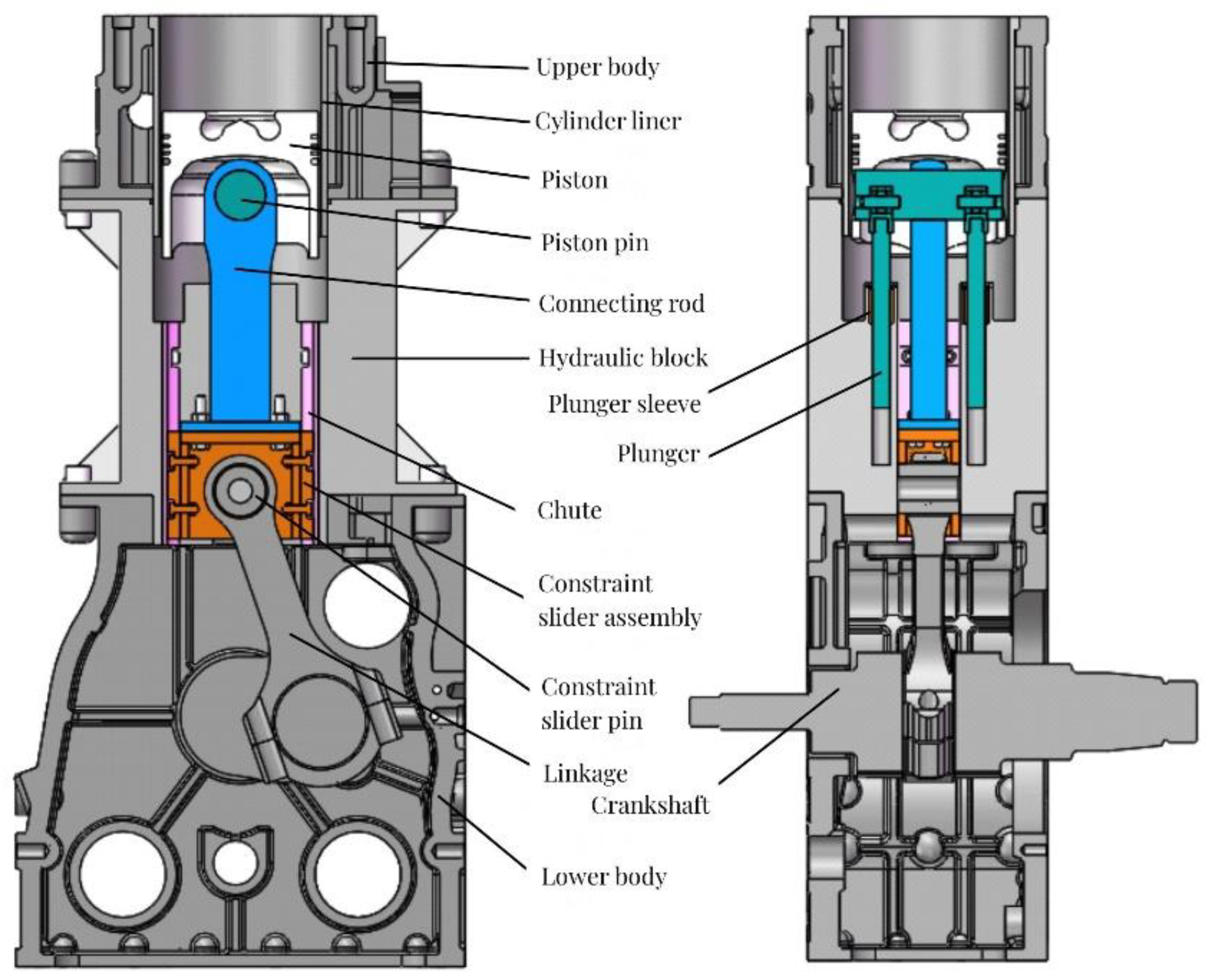
The overall structure of the hydraulic engine is shown in
Figure 1, with the cylinder head, upper body, hydraulic integration block, lower body, and oil sump arranged axially. The main motion system consists of a piston, piston pin, plunger, connecting rod, constrained slider assembly, linkage, crankshaft, and flywheel. To avoid excessive height, the constrained groove and reciprocating plunger pump system are integrated into the hydraulic integration block. The constrained device assembly utilizes a square slider design, embedded between two plunger pump chambers and featuring a groove in the hydraulic integration block to constrain the radial motion of the square slider, forming a complete square slider constraint structure. Within the hydraulic integration block, there are two plunger cylinders, hydraulic oil passages, grooves, lubricating oil passages, and through holes for structures such as valve push rods. This design maximizes the spatial structure inside the hydraulic integration block, enabling the simultaneous integration of the hydraulic components, mechanical constraints, and engine lubrication functions, ensuring both a compact overall structure and the integrity of the engine working system.
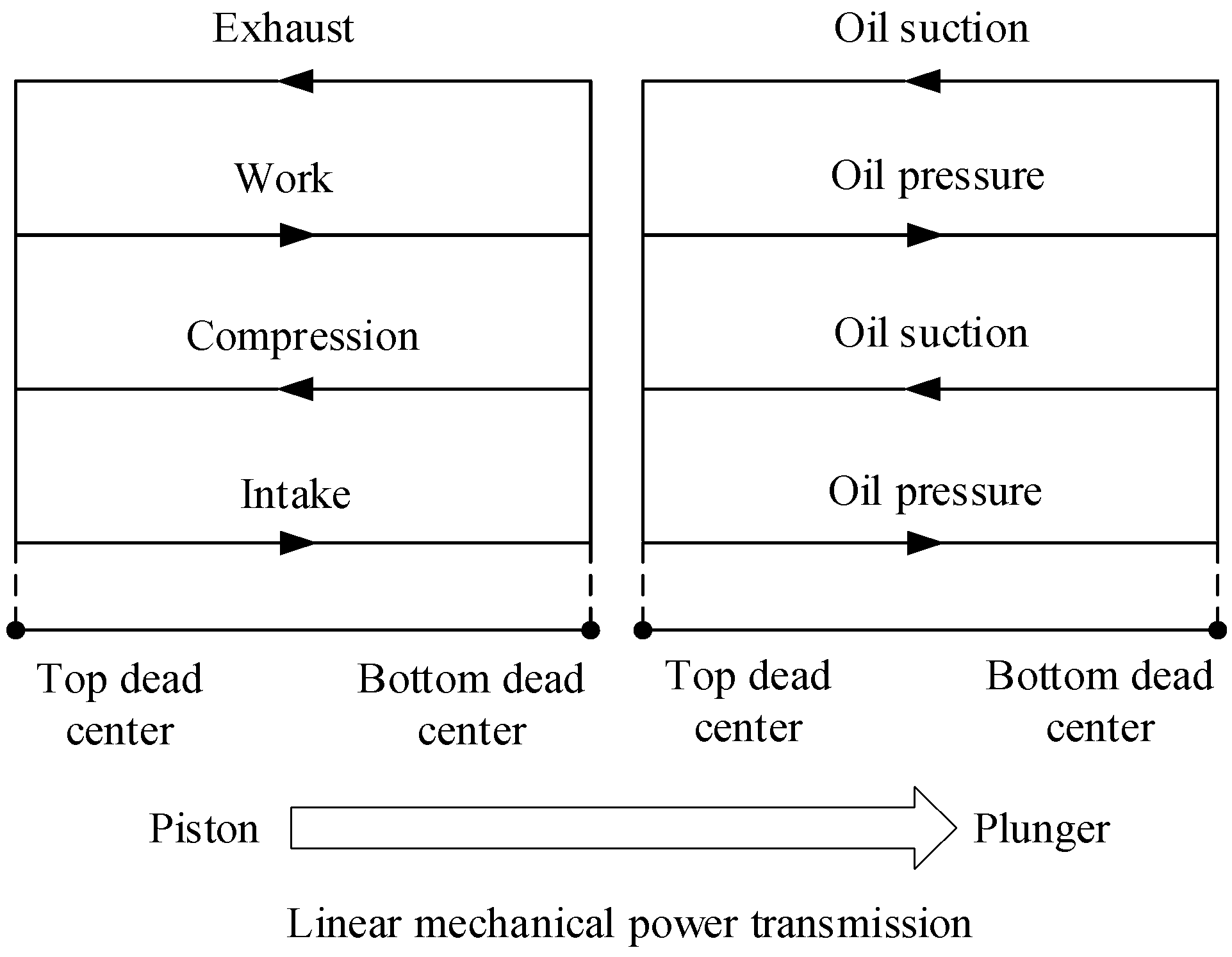
A single-cylinder axial constrained piston hydraulic engine comprises three working chambers and related auxiliary systems, as shown in
Figure 2. The first working chamber is the combustion chamber, where the expanding pressure generated by diesel combustion in the cylinder drives the piston’s linear motion. The second working chamber is the pump chamber, where the piston pin drives the plunger’s reciprocating linear motion within the pump chamber, working in conjunction with the distribution valve to perform oil suction and discharge. During oil suction, the piston pin moves the plunger upward, creating a vacuum in the pump chamber. The hydraulic oil is drawn into the pump chamber through the suction check valve. During oil discharge, the piston pin pushes the plunger downward, and the hydraulic oil in the pump chamber is forced out through the discharge check valve, generating high-pressure oil and completing the oil suction and pressure cycle. The third working chamber is the rotational power chamber, where the motion of the connecting rod, constrained slider assembly, linkage, crankshaft, and flywheel converts the piston’s linear motion into the rotational motion of the crankshaft and flywheel assembly. The overall structure defines the upper and lower limits of the piston’s motion, with the crankshaft connected to the flywheel, which serves as an energy storage device, ensuring the continuous operation of the main motion system. The auxiliary systems include the fuel supply system, valve mechanism, lubrication system, cooling system, and starting system, among others.
3. Analysis of Hydraulic Engine Machine–Hydraulic Coordination Mechanism and Power Flow Transfer Process
Theoretical research forms the basis for simulation and experimental analysis. This paper focuses on a single-cylinder constrained piston hydraulic engine and analyzes the coordination mechanism between the mechanical and fluid components during the normal operating cycle. This includes the coordination mechanisms for power transmission, mechanical–fluid conversion, and energy conversion, as well as an analysis of the power flow path of the hydraulic engine.
3.1. Analysis of Hydraulic Engine Machine–Hydraulic Coordination Mechanism
The power transmission and coordination mechanism of a hydraulic engine during one working cycle is shown in
Figure 3. Taking one working cycle of the engine as an example, during the power stroke, the expanding pressure generated by the combustion of fuel in the engine cylinder acts on the surface of the piston, driving its movement. Using the piston pin as the power distribution point, one portion of the power is directly used to drive the plunger to generate the hydraulic energy for oil pressure, while the other portion of the power drives the constrained slider through the linkage to perform the linear motion. Subsequently, through the connecting rod, the power is transmitted to the crankshaft and flywheel, converting the power into a rotational force. At this time, part of the energy from the power stroke is absorbed by the flywheel to maintain the stability of the crankshaft speed. During the other strokes, the energy absorbed by the flywheel is released, and the power is transmitted to the piston pin through the crank-connecting rod structure. One portion of the power drives the plunger to continue the oil suction and pressure work, while the other portion of the power drives the piston to create the conditions for the next power stroke.
The linear-to-hydraulic energy conversion mechanism in the hydraulic engine is determined by the connection between the piston and the plunger.
Figure 4 illustrates the coordination mechanism for the mechanical-to-fluid conversion during one working cycle of the hydraulic engine. The connection between the piston and the plunger is a secure attachment, and the movement characteristics of the plunger determine the flow rate characteristics of the output hydraulic oil. Both the piston and the plunger move in the same axial direction with consistent motion characteristics. In a complete cycle of engine operation, the reciprocating plunger pump completes two cycles of oil suction and pressure work [
13,
14,
15,
16].
During the energy conversion process, there is a power distribution in the transformation of the linear mechanical energy to rotational mechanical energy and hydraulic energy. The two divided portions of power need to work in coordination to achieve the optimal performance of the hydraulic engine.
Figure 5 illustrates the energy conversion process of the hydraulic engine. From the figure, it can be observed that the piston stroke affects the rotational speed, while the plunger stroke influences the flow rate. Due to their fixed connection, the piston stroke and the plunger stroke exhibit coordination in the hydraulic engine regarding both the rotational power output and fluid power output.
3.2. Analysis of Hydraulic Engine Power Flow Transfer Process
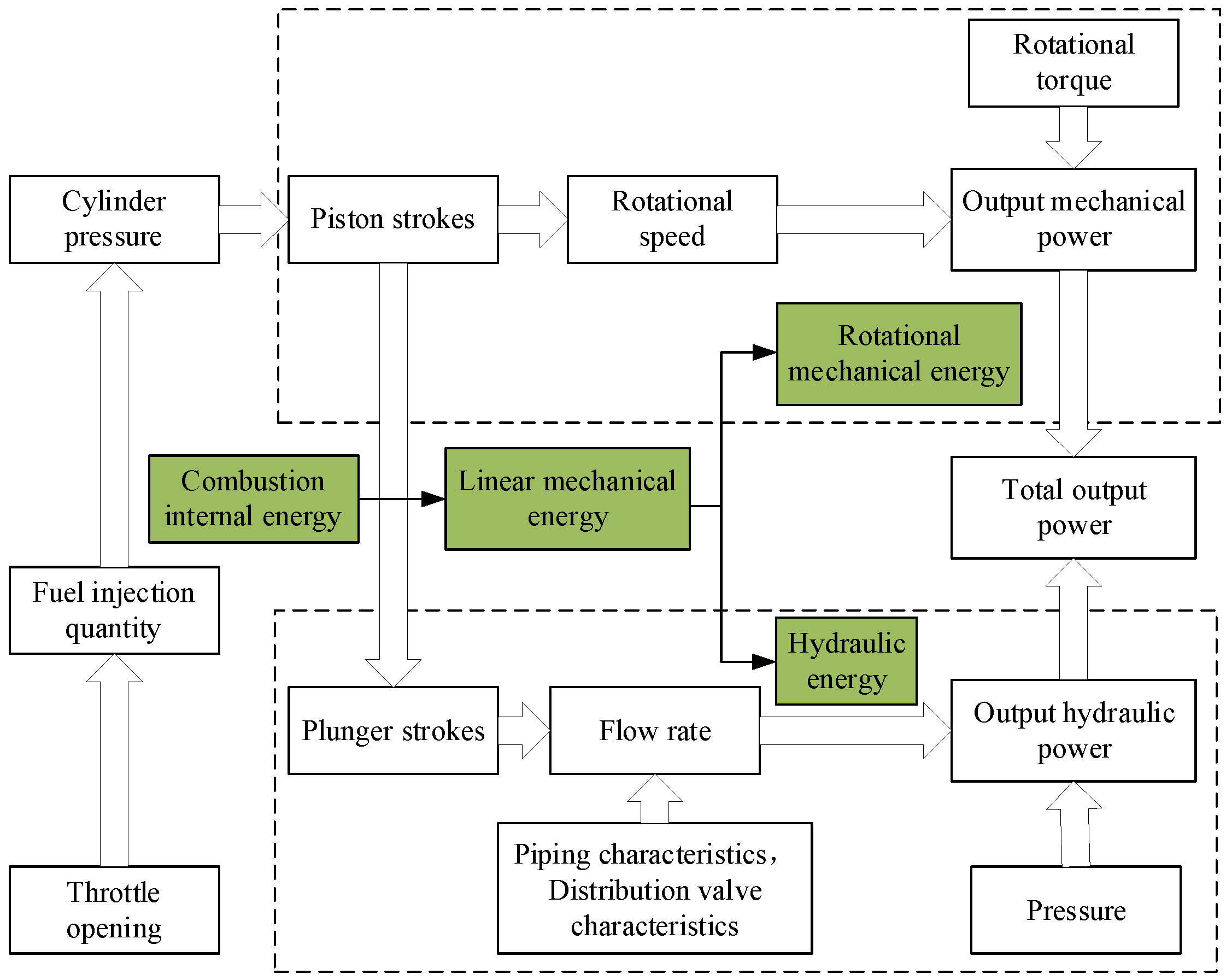
The hydraulic engine integrates the reciprocating plunger pump system into the engine. After the internal energy of fuel is converted into the linear mechanical energy of the piston, it is divided and converted into the hydraulic energy and rotational mechanical energy for output. The thermal–mechanical–hydraulic power flow coupling and conversion process is shown in
Figure 6.
4. Establishment of Mathematical Model for a Hydraulic Engine
Since the study of engines involves knowledge of thermodynamics, dynamics, and fluid mechanics, this paper has established a mathematical model to pave the way for a subsequent simulation validation and experimental testing of the physical model.
4.1. Establishment of a Thermodynamic Model
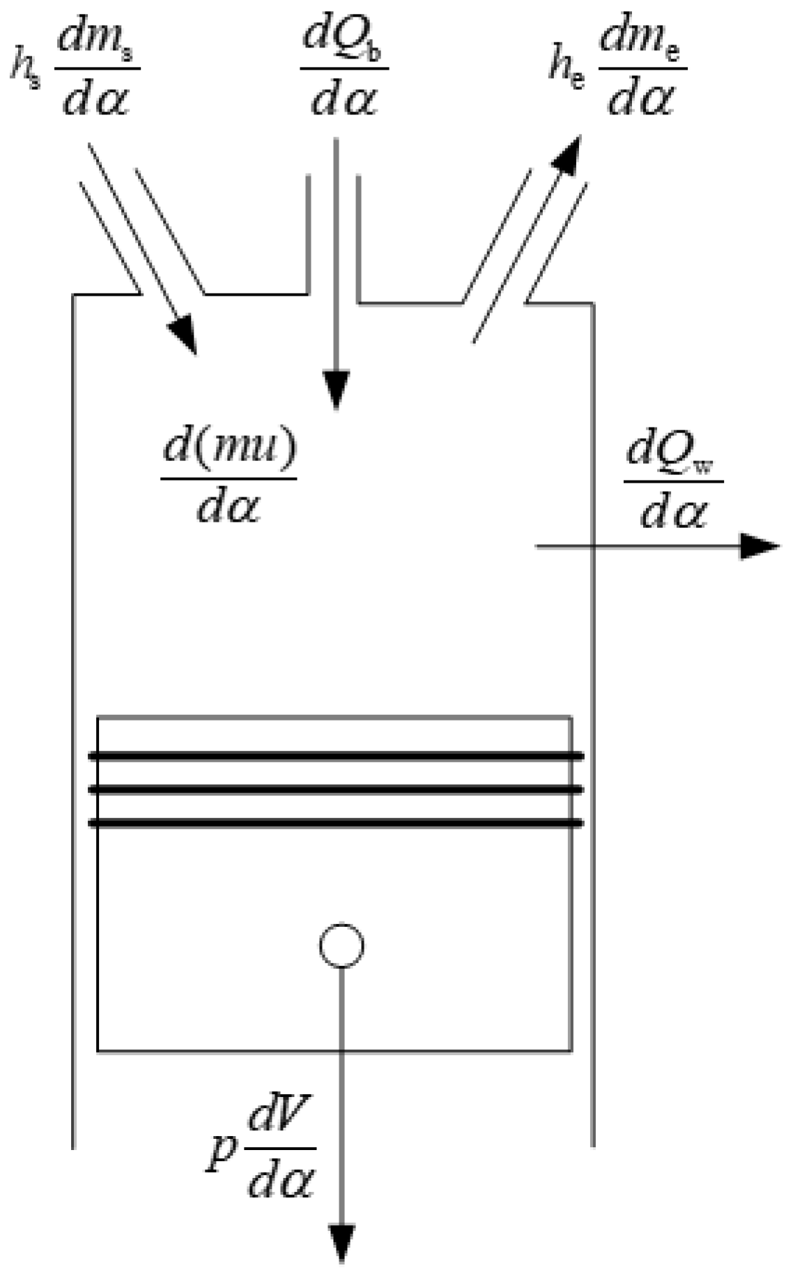
The thermal energy of the fuel as the initial energy of the hydraulic engine and its performance in all aspects of combustion in the cylinder determine the working effect of the engine, and the combustion of the fuel in the cylinder includes chemical, physical, heat transfer, flow, and other complex working processes, in which the cylinder can be equated to a thermal system, so as to more easily describe the change process of the work mass in the cylinder [
17,
18,
19,
20], based on the working process in the cylinder (as shown in
Figure 7), the thermodynamic models such as cylinder heat transfer model, intake, and exhaust flow model, and the combustion exothermic model of single-cylinder axially constrained piston hydraulic engine are established, so as to obtain the variable models of the engine work pressure change and fuel consumption rate.
4.1.1. Cylinder Heat Transfer Model
The heat transfer of high temperature gas in the cylinder is related to the working medium temperature, cylinder wall temperature, and heat transfer coefficient. The heat transfer rate calculation equation is [
21]:
where
Qw is the heat transferred through the cylinder wall, kJ;
ah is the heat transfer coefficient, which can be calculated according to the Woschni formula;
Ac is the contact area between the working medium and the system boundary (the contact area includes the piston top surface area, the cylinder head area and the cylinder liner area between the piston top and the cylinder head), mm
2;
T is the instantaneous temperature of the working medium in the cylinder, K;
Twi is the average temperature of heat transfer on the cylinder wall, K.
4.1.2. Intake and Exhaust Flow Model
The process of gas flow through the inlet and exhaust port can be treated as a stable flow process, and the flow rate through the gas port is calculated by the formula [
22]:
where
ω is the engine angular speed, rad/s;
μ is the flow coefficient;
Aq is the instantaneous flow area, m
2;
ϕ is the gas flow function;
pq is the working medium pressure before the air inlet, Pa;
Vq is the volume of working medium before the air inlet, m
3.
The change rate of air inlet flow is:
where
μs is the inlet flow coefficient;
As is the instantaneous flow area of the air inlet, cm
2;
ps is the working medium pressure before the air inlet, MPa;
Ts is the working medium temperature before the air inlet, K;
Rs is the working gas constant before the air inlet, J/(kg·K);
ks is the adiabatic index of the working medium before the air inlet;
p is the working medium pressure behind the air inlet, MPa.
Due to the large pressure difference between the combustion chamber and the outside at the exhaust port, it needs to be discussed in stages.
When
, the air flow is a supercritical flow, and the flow change rate is:
When
, the air flow is a subcritical flow, and the flow change rate is:
where
μe is the flow coefficient of the exhaust port;
Ae is the instantaneous flow area of the exhaust port, cm
2;
p is the working medium pressure in the cylinder, MPa;
Te is the working medium temperature in the cylinder, K;
Re is the gas constant of the working medium in the cylinder, J/(kg·K);
ke is the adiabatic index of the working medium in the cylinder;
pe is the exhaust pipe pressure, MPa.
4.1.3. Combustion Exothermic Model
The instantaneous exothermic rate of diesel combustion in the cylinder is [
23]:
at, J;
gf is the circulating injection volume, kg/cyc;
dx/
dα is the diesel combustion exothermic rate;
Hu is the fuel low heat value;
ηu is the combustion efficiency, which is usually taken as 1 to simplify the calculation.
The research object of this paper is a single-cylinder diesel hydraulic engine. The exothermic rate of combustion can be characterized by a single Weibo curve. The fuel combustion percentage in the Weibo formula is:
According to Equation (7), the exothermic rate function of single Weibo combustion is:
where
m is the combustion quality index, taking the value mainly according to the engine model, speed, and other factors selected, for the speed is not for a high diesel engine, taking a value of generally 0.5~1; α is the instantaneous rotation angle of the crankshaft; α
z is the combustion duration angle; α
b is the initial angle of combustion.
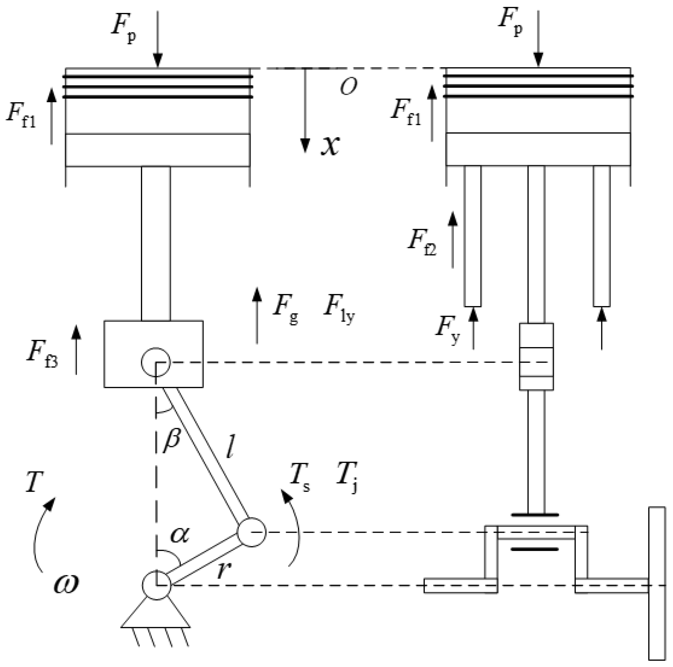
4.2. Force Analysis of Main Motion System
In the hydraulic engine, the hydraulic plunger is integrated in the lower part of the piston pin, with added structures such as the linkage and constraint slider, resulting in significant changes to the main motion system compared to the prototype machine. It not only needs to convert the linear mechanical power to the rotational mechanical power but also has to undertake the conversion of the linear mechanical power to the fluid power. During its operation, the piston–piston pin–plunger–linkage–constraint slider assembly-constraint slider pin moves in a reciprocating linear motion, while the linkage swings in a reciprocating motion around the constraint slider pin, and the crankshaft rotates. The main motion system is subject to forces as shown in
Figure 8.
The force of working medium in the cylinder on the piston is [
24]:
where
p is the working medium pressure, MPa;
D is the piston top diameter, m.
The whole main motion system has three parts of friction, namely, the friction between the piston and the cylinder sleeve
Ff1, the friction between the piston and the plunger sleeve
Ff2, and the friction between the constraint slider and the chute
Ff3. The total friction is:
The force of hydraulic oil on the plunger in the reciprocating piston pump system is:
where
n is the number of plunger;
d is the plunger diameter, m;
ph is the hydraulic oil pressure in the plunger cylinder, MPa.
The inertial force on the linear motion component is:
where
mzd is the equivalent mass generated by the motion of the linear motion component.
where
mzj is the mass of linear motion component;
mlzd is the equivalent mass transferred to the linear motion component when the linkage moves.
where
ml is the mass of linkage, kg;
l is the center distance between the small end and the big end of the linkage, m;
ls is the distance between the center of the small end of the linkage and the center of mass, m.
The horizontal component of the force acting on the linear motion component by the linkage is:
where
β is the included angle between the small end of the linkage and the vertical direction.
The tangential force of the crank by the action of the linkage is:
The normal force of the crank by the action of the linkage is:
The force analysis of the linear motion component in the vertical direction yields:
where
a is the acceleration of linear motion component, m/s
2.
The force analysis of the linear motion component in the horizontal direction yields:
where
Fqx is the lateral force of the piston by the cylinder wall, N;
Fzx is the lateral force of the plunger by the plunger cylinder wall, N.
The torque equation of the crankshaft flywheel set is:
where
r is the crank radius, m;
Ts is the output torque, N·m;
Tj is the mechanical loss moment, N·m;
I is the rotational inertia of the crankshaft flywheel set, kg·m
2;
ag is the angular acceleration of crankshaft rotation, rad/s
2.
4.3. Establishment of the Pump Chamber Flow Model
The piston pin in the hydraulic engine directly drives the plunger for the reciprocating linear motion. Ignoring the effect of the internal clearances of the mechanical connecting components, it can be considered that the motion of the piston is consistent with that of the plunger. The movement of the plunger is related to the change of pump chamber volume, that is, the output flow rate of the plunger pump is proportional to the piston speed [
25,
26].
The power end of the plunger pump is the plunger, and the hydraulic end is the pump chamber. According to the motion displacement of the linear motion component, the volume in the pump chamber can be obtained as:
where
d is the plunger diameter, m.
According to the motion speed of the linear motion component, the instantaneous flow in the pump cavity can be obtained as follows:
According to the instantaneous flow output in the pump cavity, the pressure change rate in the pump cavity can be obtained as follows:
where
pb is the pressure in the pump chamber, MPa;
K is the liquid bulk modulus,
K = 2 GPa.
5. Simulation Model and Analysis
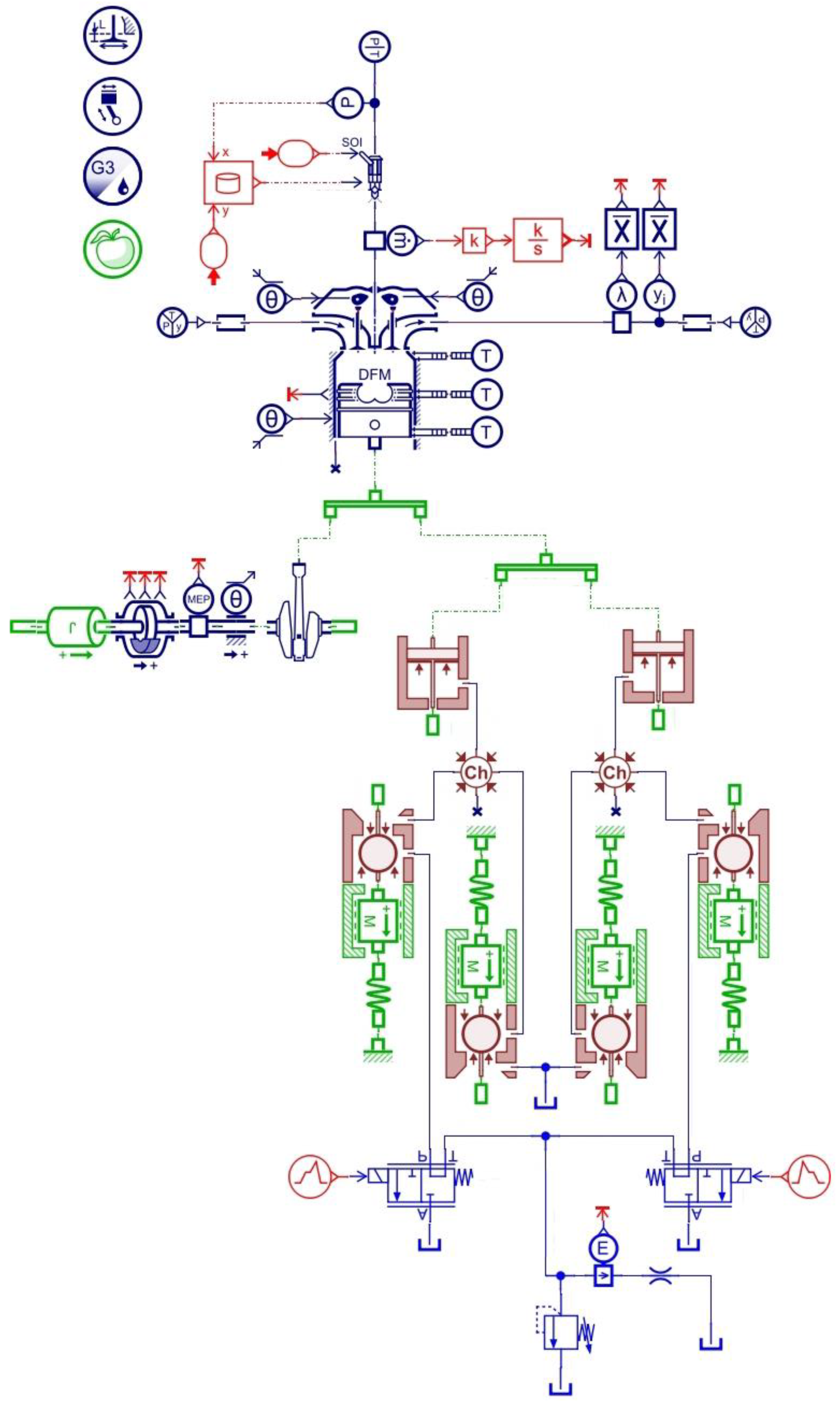
In this paper, physical models of a single-cylinder diesel engine and a reciprocating plunger pump were built using AMESim software. The models were parameterized based on the parameters of the prototype and relevant components. Coupling connections were made according to the principles of hydraulic engines for simulation analysis.
5.1. Thermal–Mechanical–Hydraulic Coupling Simulation Model
Figure 9 shows the schematic model of a single-cylinder diesel engine built using AMESim software in sketch mode. The modeling of the single-cylinder diesel engine employs an actual experimental fuel injection rate lookup table model to simulate the fuel injection process. The parameters are set based on the prototype engine’s parameters at rated speed, with specific values shown in
Table 1.
Figure 10 depicts the reciprocating pump system and distribution system model built using AMESim software. The pump chamber utilizes the BAP11 model from the hydraulic component library, assembled into the plunger cylinder and plunger section. The check valve is formed by combining the BAP22 model from the hydraulic component library with the MAS005 model from the mechanical library to create a directional check valve. As the hydraulic engine employs a direct connection between the plunger and the piston pin, the linear motion of the plunger is directly provided by the piston. Therefore, the stroke of the reciprocating plunger pump matches the piston stroke of the engine. The relevant structural parameters are set according to the design specifications, and the specific parameters for the distribution system involve the setting of the pipeline and check valve parameters, with the precise values shown in
Table 2.
The thermal–mechanical–fluid model of the hydraulic engine requires coupling connections between the single-cylinder diesel engine model and the reciprocating plunger pump model based on the principles of hydraulic engines. In the hydraulic engine, the power distribution pathway involves the linear power of the piston being divided by the piston pin. One path transfers the power to the oil pressure plunger, converting it into the fluid power, while the other path converts the power through the crank-connecting rod mechanism into the rotational mechanical power. Therefore, the key integration point between the single-cylinder diesel engine model and the reciprocating plunger pump model lies in the division of linear mechanical power from the piston. In this paper, the LCON13-1 component from the mechanical application library is used for connection, allowing for the implementation of power distribution.
Figure 11 shows the integrated thermal–machine–hydraulic coupling simulation model, which can simulate and verify the effect of the hydraulic engine’s machine–hydraulic coordination working mechanism, and also analyze the transient characteristics of the engine, the motion characteristics of the components and the characteristics of the output high-pressure oil, etc.
5.2. Analysis of Simulation Results
5.2.1. Analysis of Thermodynamic Characteristics
The temperature profile of the engine cylinder is depicted in
Figure 12, with the highest temperature reaching 1350 K during the power stroke.
Figure 13 illustrates the cylinder volume variation, which exhibits a sinusoidal pattern resembling a sine curve. This graph allows us to observe the changes in the cylinder volume as the piston moves between the top dead-center and bottom dead-center positions. In
Figure 14, the curve represents the changes in engine cylinder pressure throughout each working cycle. Notably, the cylinder pressure can reach up to 110 bar during diesel combustion and expansion.
5.2.2. Analysis of Plunger Dynamic Characteristics
The comprehensive thermal–machine–hydraulic coupling model is simulated with a simulated load pressure drop set to 10 MPa, representing the working pressure of the hydraulic system. The research object in this simulation is the plunger, as depicted in
Figure 15, showing the curve of plunger force variation. From the figure, it can be observed that during the pressure oil stroke, the plunger force gradually increases to 2150 N and then decreases to 0. On the other hand, during the oil suction stroke, the plunger only needs to overcome the spring force of the oil suction valve for oil absorption, resulting in a plunger force of up to 5.1 N.
The fluctuation in the plunger speed is the primary cause of the flow pulsation.
Figure 16 displays the displacement curve of the plunger, demonstrating the change in its position. Taking the top dead-center of the plunger motion as the initial position, the maximum displacement of the plunger is 130 mm, representing the working stroke of 130 mm, which aligns with the engine’s design parameters. In
Figure 17, the speed curve of the plunger is presented. As per the characteristics of reciprocating plungers, the plunger undergoes an initial acceleration followed by a deceleration during the oil suction and pressure processes. According to the curve parameters depicted in the figure, the average speed of the plunger’s reciprocating motion is 6.5 m/s. By comparing the motion characteristics of the plunger with those of the piston, it is evident that the curve changes are consistent. This demonstrates the mechanical–hydraulic coordination mechanism of the hydraulic engine, where the piston directly propels the plunger to move in a reciprocating straight line to accomplish the tasks of oil suction and pressure.
5.2.3. Analysis of Pump Chamber Flow Rate
As the hydraulic end of the hydraulic engine-hydraulic conversion, the pump chamber undertakes the whole process of hydraulic oil suction to discharge and pressurization.
Figure 18 shows the volume change curve of a single pump chamber in a working cycle of the hydraulic engine, the curve reflects the volume change in the hydraulic engine pump chamber due to the movement of the plunger. The engine works for one cycle, and the pump chamber completes two oil suction and pressure cycles.
Figure 19 illustrates the flow variation curve of the oil port in a single pump chamber, representing the changes in hydraulic oil flow at the oil port during one cycle of operation in the hydraulic engine. During the oil suction phase, the flow initially increases and then decreases until the plunger reaches the top dead-center, indicating the completion of oil suction. On the other hand, during the oil drainage phase, the flow gradually increases and then decreases until the plunger reaches the bottom dead-center, marking the completion of oil drainage.
5.2.4. Analysis of Oil Drain Valve Characteristics
Figure 20 depicts the displacement variation curve of the oil discharge valve spool, with three notable points labeled as a, b, and c. Point a represents the valve opening point, point b represents the maximum flow point as the valve passes through, and point c represents the valve closing point. The time taken from the valve opening to reaching the maximum lift is 0.005 s, while the time from the maximum lift to the valve closure is 0.018 s. The valve completes one cycle of operation in 0.023 s, with a hysteresis time of 0.003 s.
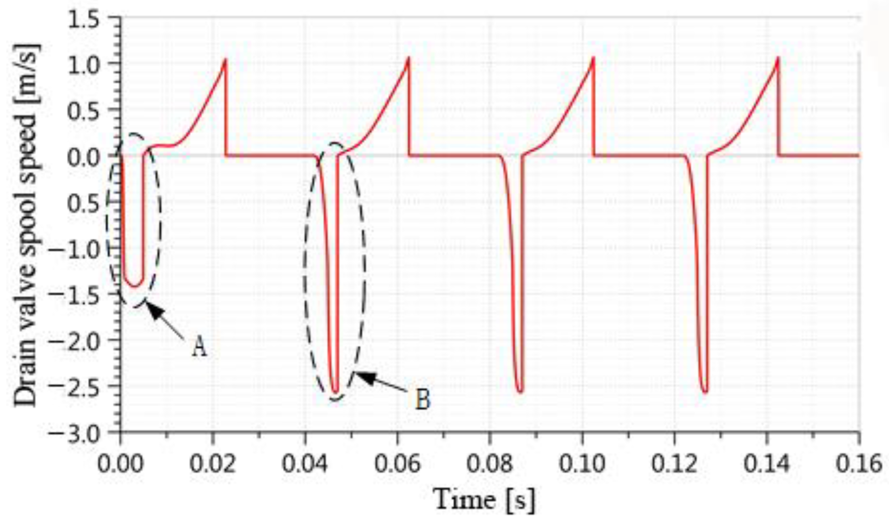
Figure 21 displays the spool speed variation curve of the oil discharge valve. The difference in the maximum speed between the A and B regions is due to the presence of a dead zone within the valve seat. When the initial oil discharge occurs, a portion of the hydraulic oil enters this dead zone, resulting in a slower maximum speed in the A region compared to the B region.
Figure 22 displays the flow variation curve of the oil drain check valve. Notably, the output flow in area C of the figure is negative. There are two reasons for this phenomenon. Firstly, hydraulic oil leakage occurs during the oil drainage process. Secondly, hydraulic oil returns during the oil drainage process. The movement of the valve spool in the oil drain valve lags behind, resulting in the valve spool not returning to its initial position while the plunger pump starts to suction oil. Consequently, a small amount of the hydraulic oil is drawn back into the pump chamber before the valve spool of the oil drain valve fully returns to its initial position. This continues until the oil drain valve is completely closed.
5.2.5. Analysis of Output Flow Characteristics
Once the hydraulic oil is discharged from the pump chamber, it passes through the discharge check valve to generate the high-pressure oil for the load. The reliability of the system is determined by the range of flow pulsation. Large fluctuations can negatively impact the load performance and potentially damage the hydraulic components.
Figure 23 displays the output flow variation curves of the simulation model in both single-pump and double-pump operation modes. Since the hydraulic engine’s pump system is equivalent to a reciprocating piston pump system, there is an idle period during suction, and the plunger’s movement speed undergoes changes during operation. Consequently, this leads to significant fluctuations in the output flow of high-pressure oil. In the single-pump operation, the maximum flow rate is 110 L/min, the minimum flow rate is −11 L/min, and the maximum difference is 122 L/min. In the double-pump operation, the maximum flow rate is 220 L/min, the minimum flow rate is −22 L/min, and the maximum difference is 248 L/min. The fluctuation amplitude is relatively large. Therefore, a method to restrain the flow fluctuations is required to ensure the reliability of the output hydraulic oil. Area A in the figure indicates the occurrence of hydraulic oil backflow during the oil discharge process for both the single and double pumps.
By simulating the load with a pressure drop of 10 MPa, which represents the working pressure, the hydraulic engine’s instantaneous power can be determined. The average power can be obtained through data post-processing using AMESim software, as depicted in
Figure 24. From the figure, it is evident that the output hydraulic power of the hydraulic engine is approximately 10.1 kW, slightly lower than the theoretical power of 11.7 kW. This difference can be attributed to the pressure drops caused by the hydraulic resistance in the pipeline and valves, resulting in a simulation power rate that is slightly below the theoretical power.
6. Conclusions
On the basis of designing a single-cylinder axial constrained piston hydraulic engine, the coordination mechanism of power transmission, mechanical-fluid conversion, and energy conversion processes in the hydraulic engine were analyzed. Additionally, the power flow path was established. Thermodynamic, dynamic, and fluidic models were developed for the hydraulic engine, including its thermal model, main motion system dynamic model, and hydraulic module fluidic model.
The thermal–mechanical–fluid coupling model of the hydraulic engine was built, and the model parameters were set based on the parameters of the prototype and related components for simulation analysis. The correctness of the thermodynamic model was verified by analyzing the change in the hydraulic engine cylinder pressure. Then, the displacement and velocity changes of the piston and plunger were analyzed to verify the machine-fluid conversion mechanism. Next, the changes in the pump chamber flow rate, discharge valve characteristics, and output flow rate characteristics were analyzed. Under the premise of improving the overall efficiency, the combustion characteristics and output power index of the hydraulic engine met the expected design requirements, with an output hydraulic power of approximately 10.1 kW.
The output flow rate of the discharge valve has negative values, mainly caused by hydraulic oil leakage and reflux. The maximum amplitude difference of the hydraulic engine’s output hydraulic oil flow rate is 248 L/min, with significant flow rate fluctuations. Therefore, methods to suppress flow rate pulsations are required to ensure the reliability of the output flow rate.
Author Contributions
Conceptualization, X.B. and L.L.; methodology, L.L.; software, X.B.; validation, X.O. and T.Z.; formal analysis, X.B.; investigation, Y.W.; resources, L.L.; data curation, Y.W.; writing—original draft preparation, X.B.; writing—review and editing, L.L.; visualization, T.Z.; supervision, X.O.; project administration, L.L. All authors have read and agreed to the published version of the manuscript.
Funding
This research was supported by the National Natural Science Foundation of China (No. 52075307) and the Open Foundation of the State Key Laboratory of Fluid Power and Mechatronic Systems (GZKF-202230).
Institutional Review Board Statement
Not applicable.
Informed Consent Statement
Not applicable.
Data Availability Statement
Not applicable.
Conflicts of Interest
The authors declare no conflict of interest.
Nomenclature
| Heat transferred through the cylinder wall, kJ |
| Heat transfer coefficient |
| Contact area between the working medium and the system boundary, mm2 |
| Instantaneous temperature of the working medium in the cylinder, K |
| Average temperature of heat transfer on the cylinder wall, K |
| Engine angular speed, rad/s |
| Flow coefficient |
| Instantaneous flow area, m2 |
| Gas flow function |
| Working medium pressure before the air inlet, Pa |
| Volume of working medium before the air inlet, m3 |
| Inlet flow coefficient |
| Instantaneous flow area of the air inlet, cm2 |
| Working medium pressure before the air inlet, MPa |
| Working medium temperature before the air inlet, K |
| Working gas constant before the air inlet, J/(kg·K) |
| Adiabatic index of the working medium before the air inlet |
| Flow coefficient of the exhaust port |
| Instantaneous flow area of the exhaust port, cm2 |
| Working medium temperature in the cylinder, K |
| Gas constant of the working medium in the cylinder, J/(kg·K) |
| Adiabatic index of the working medium in the cylinder |
| Exhaust pipe pressure, MPa |
| Diesel exothermic heat, J |
| Circulating injection volume, kg/cyc |
| Diesel combustion exothermic rate |
| Fuel low heat value |
| Combustion efficiency |
| Instantaneous rotation angle of the crankshaft |
| Initial angle of combustion |
| Combustion duration angle |
| Piston top diameter, m |
| Friction between piston and cylinder sleeve |
| Friction between piston and plunger sleeve |
| Friction between constraint slider and chute |
| Number of plunger |
| Plunger diameter, m |
| Hydraulic oil pressure in the plunger cylinder, MPa |
| Equivalent mass generated by the motion of the linear motion component |
| Mass of linear motion component |
| Equivalent mass transferred to the linear motion component when the linkage moves |
| Mass of linkage, kg |
| Center distance between the small end and the big end of the linkage, m |
| Distance between the center of the small end of the linkage and the center of mass, m |
| Included angle between the small end of the linkage and the vertical direction |
| Acceleration of linear motion component, m/s2 |
| Lateral force of the piston by the cylinder wall, N |
| Lateral force of the plunger by the plunger cylinder wall, N |
| Crank radius, m |
| Output torque, N·m |
| Mechanical loss moment, N·m |
| Rotational inertia of the crankshaft flywheel set, kg·m2 |
| Angular acceleration of crankshaft rotation, rad/s2 |
| Plunger diameter, m |
| Pressure in the pump chamber, MPa |
| Liquid bulk modulus, K = 2 GPa |
References
- Novotný, P.; Vacula, J.; Hrabovský, J. Solution strategy for increasing the efficiency of turbochargers by reducing energy losses in the lubrication system. Energy 2021, 236, 121402. [Google Scholar] [CrossRef]
- Wróblewski, P.; Iskra, A. Problems of Reducing Friction Losses of a Piston-Ring-Cylinder Configuration in a Combustion Piston Engine with an Increased Isochoric Pressure Gain; SAE Technical Paper 2020-01-2227; SAE: Warrendale, PA, USA, 2020. [Google Scholar]
- Gu, C.; Wang, R.; Tian, T. Modeling the Fatigue Wear of the Cylinder Liner in Internal Combustion Engines during the Break-In Period and Its Impact on Piston Ring Lubrication. Lubricants 2019, 7, 89. [Google Scholar] [CrossRef]
- Jocsak, J.; Li, Y.; Tian, T.; Wong, V. Modeling and Optimizing Honing Texture for Reduced Friction in Internal Combustion Engines; SAE Technical Paper 2006-01-0647; SAE: Warrendale, PA, USA, 2006. [Google Scholar]
- Geng, H.; Wang, Y.; Zhen, X.; Liu, Y.; Li, Z. Study on adaptive behavior and mechanism of compression ratio (or piston motion profile) for combustion para-meters in hydraulic free piston engine. Appl. Energy 2018, 211, 921–928. [Google Scholar] [CrossRef]
- Jia, B.; Mikalsen, R.; Smallbone, A.; Roskilly, A.P. A Study and Comparison of Frictional Losses in Free-piston Engine and Crankshaft Engines. Appl. Therm. Eng. 2018, 140, 217–224. [Google Scholar] [CrossRef]
- Li, C.; Wang, Y.; Geng, H.; Li, Z.; Dong, X.; Zhen, X. Analysis and optimization simulation of injection mode of two-stroke port injection hydraulic free piston engine. J. Wuhan Univ. 2021, 54, 255–262. [Google Scholar]
- Kim, J.; Bae, C.; Kim, G. The Operation Characteristics of a Liquefied Petroleum Gas (LPG) Spark-ignition Free Piston Engine. Fuel 2016, 183, 304–313. [Google Scholar] [CrossRef]
- Mikalsen, R.; Roskilly, A.P. The control of a free-piston engine generator. Part 1: Fundamental analyses. Appl. Energy 2010, 87, 1273–1280. [Google Scholar] [CrossRef]
- Xiao, J. Modeling, Simulation, and Optimization Design of the Flow Control Valve System in a Hydraulic-Constrained Piston Engine. Master’s Thesis, Qingdao University, Qingdao, China, 2006. [Google Scholar]
- Yin, K. Parameterized Design of the Crankshaft and Optimization of the Balance Block Shape in a Hydraulic-Constrained Piston Engine. Master’s Thesis, Qingdao University, Qingdao, China, 2013. [Google Scholar]
- Huang, F. Theoretical and Experimental Research on Micro Free Piston Engine. Ph.D. Thesis, University of Chinese Academy of Sciences, Beijing, China, 2020. [Google Scholar]
- Jian, C.; Ma, L.; Yang, W.; Huang, Q.; Xu, J.; Zhai, H.; Cao, G. Influence of high temperature degaussing on lifting capacity of linear motor reciprocating pump. J. Phys. Conf. Ser. 2021, 2109, 012009. [Google Scholar] [CrossRef]
- Timashev, O.E.; Urazakov, K.R.; Volkov, M.G.; Garifullin, A.R.; Khalfin, R.S.; Brot, A.R. Method of calculation for installations with electrical submersible reciprocating pump for oil production (Russian). Oil Ind. J. 2020, 2020, 72–76. [Google Scholar]
- Wang, T.; Wang, G.; Dai, L.; Chen, L.; Qiu, S.; Li, R. Motion mechanism study on the valve disc of an ultra-high pressure reciprocating pump. Mech. Syst. Signal Process. 2021, 160, 107942. [Google Scholar] [CrossRef]
- Zhenjie, G.; Changqing, B.; Hongyan, Z. Nonlinear Dynamic Modeling and Fluid–Mechanism Interaction Analysis of Reciprocating Pump–Pipeline System. Proc. Inst. Mech. Eng. Part I J. Syst. Control Eng. 2021, 235, 869–880. [Google Scholar]
- Zhang, S.; Zhao, Z.; Zhao, C. Simulation study on the in-cylinder process of hydraulic free piston diesel engine. Combust. Sci. Technol. 2015, 21, 447–452. [Google Scholar]
- Zhao, Z.; Zhang, F.; Guo, F. Study on combustion process in cylinder of hydraulic free piston diesel engine. J. Eng. Thermophys. 2015, 36, 445–450. [Google Scholar]
- Geng, H. Research on Operation Mechanism and Combustion Process of Hydraulic Free Piston Engine. Ph.D. Thesis, Tianjin University, Tianjin, China, 2020. [Google Scholar]
- Geng, H.; Wang, Y.; Xi, B.; Li, Z.; Zhen, X.; Fu, C.; Hu, Y. Study on HCCI combustion improvement by using dual assisted compression ignition (DACI) on a hydraulic free piston engine fueled with methanol fuel. Appl. Therm. Eng. 2020, 167, 114782. [Google Scholar] [CrossRef]
- Hu, S. Research on Combustion Simulation Model of Direct Injection Pressure Ignition Engine for Control Purposes. Ph.D. Thesis, Harbin Engineering University, Harbin, China, 2019. [Google Scholar]
- Lai, C.; Chen, Y.; Wang, Y.; Duan, M.; Zhou, Y. Numerical Simulation and Optimization Analysis of In-Cylinder Combustion in a Certain Diesel Engine. J. Chongqing Univ. Technol. 2017, 31, 23–30. [Google Scholar]
- Chen, L.; Liu, D. Modeling and Simulation of Automotive Diesel Engine. Intern. Combust. Engines Parts 2020, 20, 14–15. [Google Scholar]
- Liu, J. Research on Virtual Experiment System for Diesel Engine. Master’s Thesis, Chang’an University, Xi’an, China, 2014. [Google Scholar]
- Zhou, Y.; Kumar, A.; Parkash, C.; Vashishtha, G.; Tang, H.; Xiang, J. A novel entropy-based sparsity measure for prognosis of bearing defects and development of a sparsogram to select sensitive filtering band of an axial piston pump. Measurement 2022, 203, 111997. [Google Scholar] [CrossRef]
- Zhou, Y.; Kumar, A.; Parkash, C.; Vashishtha, G.; Tang, H.; Glocawz, A.; Dong, A.; Xiang, J. Development of entropy measure for selecting highly sensitive WPT band to identify defective components of an axial piston pump. Appl. Acoust. 2023, 203, 109225. [Google Scholar] [CrossRef]
Figure 1.
A hydraulic engine structure cross-section.
Figure 1.
A hydraulic engine structure cross-section.
Figure 2.
The working principle of a hydraulic engine.
Figure 2.
The working principle of a hydraulic engine.
Figure 3.
The hydraulic engine power transmission coordinated working mechanism.
Figure 3.
The hydraulic engine power transmission coordinated working mechanism.
Figure 4.
The hydraulic engine machine-to-hydraulic conversion coordinated working mechanism.
Figure 4.
The hydraulic engine machine-to-hydraulic conversion coordinated working mechanism.
Figure 5.
The hydraulic engine energy conversion process.
Figure 5.
The hydraulic engine energy conversion process.
Figure 6.
The hydraulic engine power flow coupling model.
Figure 6.
The hydraulic engine power flow coupling model.
Figure 7.
A sketch of the working process of hydraulic engine cylinder.
Figure 7.
A sketch of the working process of hydraulic engine cylinder.
Figure 8.
A sketch of the main motion system force.
Figure 8.
A sketch of the main motion system force.
Figure 9.
A simulation model of a single-cylinder diesel engine.
Figure 9.
A simulation model of a single-cylinder diesel engine.
Figure 10.
A simulation model of the reciprocating plunger pump and distribution system.
Figure 10.
A simulation model of the reciprocating plunger pump and distribution system.
Figure 11.
The thermo–mechanical–hydraulic coupling simulation model of a hydraulic engine.
Figure 11.
The thermo–mechanical–hydraulic coupling simulation model of a hydraulic engine.
Figure 12.
The change curve of the cylinder temperature.
Figure 12.
The change curve of the cylinder temperature.
Figure 13.
The change curve of the cylinder volume.
Figure 13.
The change curve of the cylinder volume.
Figure 14.
The change curve of the cylinder pressure.
Figure 14.
The change curve of the cylinder pressure.
Figure 15.
The change curve of the plunger force.
Figure 15.
The change curve of the plunger force.
Figure 16.
The change curve of the plunger displacement.
Figure 16.
The change curve of the plunger displacement.
Figure 17.
The change curve of the plunger speed.
Figure 17.
The change curve of the plunger speed.
Figure 18.
The change curve of the pump chamber volume.
Figure 18.
The change curve of the pump chamber volume.
Figure 19.
The change curve of the pump chamber oil port flow.
Figure 19.
The change curve of the pump chamber oil port flow.
Figure 20.
The change curve of the oil drain valve spool displacement.
Figure 20.
The change curve of the oil drain valve spool displacement.
Figure 21.
The change curve of the drain valve spool speed.
Figure 21.
The change curve of the drain valve spool speed.
Figure 22.
The change curve of the drain valve output flow.
Figure 22.
The change curve of the drain valve output flow.
Figure 23.
The output flow change curve of single and double pump under working condition.
Figure 23.
The output flow change curve of single and double pump under working condition.
Figure 24.
The hydraulic power curve of hydraulic engine.
Figure 24.
The hydraulic power curve of hydraulic engine.
Table 1.
The simulation parameters of a single-cylinder diesel engine.
Table 1.
The simulation parameters of a single-cylinder diesel engine.
| Item | Parameter |
|---|
| Cylinder diameter (mm) | 130 |
| Crank radius (mm) | 65 |
| Linkage length (mm) | 205 |
| Displacement (L) | 1.725 |
| Rotational speed (r/min) | 1500 |
| Compression ratio | 18 |
| Oil supply pressure (MPa) | 0.04 |
| Inlet pressure drop (KPa) | 1.5 |
| Exhaust back pressure (KPa) | 3 |
Table 2.
The simulation parameters of the reciprocating piston pump and flow distribution system.
Table 2.
The simulation parameters of the reciprocating piston pump and flow distribution system.
| Item | Parameter |
|---|
| Plunger diameter (mm) | 15 |
| Pump stroke (mm) | 130 |
| Inside diameter of pipeline (mm) | 15 |
| Valve spool diameter (mm) | 20 |
| Valve seat diameter (mm) | 16 |
| Valve spool quality (g) | 62 |
| Valve spool lift (mm) | 6 |
| Spring stiffness (N/m) | 2000 |
| Disclaimer/Publisher’s Note: The statements, opinions and data contained in all publications are solely those of the individual author(s) and contributor(s) and not of MDPI and/or the editor(s). MDPI and/or the editor(s) disclaim responsibility for any injury to people or property resulting from any ideas, methods, instructions or products referred to in the content. |
© 2023 by the authors. Licensee MDPI, Basel, Switzerland. This article is an open access article distributed under the terms and conditions of the Creative Commons Attribution (CC BY) license (https://creativecommons.org/licenses/by/4.0/).


