1. Introduction
In order to make rational use of power resources and reduce the investment cost of power generation, many small hydropower and photovoltaic (PV) stations are directly connected to the end of the distribution network in remote areas [
1,
2,
3]. The regional distributed network has weak electrical connections to the main grid. They may be connected to the main grid only through a single transformer or a single line [
4,
5]. Once the line or transformer is tripped due to a fault, the regional distributed network will become an unintentional island. The randomness and lack of power regulation ability of small hydropower or PV will make it difficult for the stable operation of the island [
6,
7]. Many papers believe the asynchronous closing of unintentional islands containing distributed generators (DG) will bring security risks to power grid operation [
8,
9]. It is even more difficult for unintentional islands to connect to the main grid through reclosing [
10,
11,
12]. The regional distributed network cannot be manually re-connected to the power grid until all generators are cut off. The power outage will last for a long time.
But on the other hand, the fault self-healing of the regional distributed network has become possible because of hydropower and PV. After the regional distributed network becomes an unintentional island, small hydropower and PV can provide uninterrupted power supply to important loads on the island [
13,
14,
15]. With the increasingly mature DG technology, the latest IEEE Std 1547–2011 [
16] standard allows and encourages the users to achieve unintentional island stable operation through technical means as much as possible and to restore the connection to the power grid through reclosure or automatic standby switching. In addition, the development model of New Energy and Energy Storage (ES) is becoming mainstream. Many PV stations are configured with ES [
17,
18,
19]. This further brings the possibility of faults seamless self-healing of regional distributed networks.
Generator tripping or load shedding is an important mean to maintain the stable operation of the power system. Many papers have studied it. In [
20], a hybrid control scheme to reduce the stress level of the grid network by generator tripping or load shedding is proposed. An emergency control strategy that combines generator tripping with load shedding is proposed in [
21] in order to solve the problem of low voltage. In [
22], a method for load shedding and generator tripping based on the sensitivity theory of transient energy margin is proposed. With the rapid development of distributed generators, the generator’s power regulation ability has become better. If power regulation and generator tripping or load shedding can be combined for island stability control, the loss of load can be minimized as much as possible [
23,
24]. At present, in the distribution network with a large number of distributed generators, there is no relevant paper to study the use of ES, PV, small hydropower, and other resources within the regional distributed network for self-healing control.
The characteristics of the regional distributed network are analyzed in this paper, and a real-time island stability control method based on the operating conditions combining regulation with tripping is proposed. A comprehensive evaluation of the self-healing ability after the island is conducted. The regulation strategy is adopted preferentially to realize the stable operation of the island without losing any load. When the adjustment ability is insufficient, combined regulation and tripping strategy is adopted. A simulation test platform is built to verify the correctness of the fault self-healing system. Thus, through the research on key technologies of island stability control, this paper aims to achieve rapid self-healing of connecting channel faults in regional distributed networks. The goal of “grid-reconnection as soon as possible” and “minimizing load loss” has also been achieved. The power supply reliability of the regional distributed network is improved.
3. Fault Self-Healing Control Method of Regional Distributed Network
During normal operation of the regional distributed network, the power generated by DGs is prioritized for use by local loads. If the power is surplus or insufficient, it will exchange power with the main grid. When the connecting channel faults, if there is no stability control strategy involved, the low-frequency load shedding and high-frequency generator cutting functions of feeder protection will work. The loads and generators are cut back and forth repeatedly [
27,
28]. Finally, the connection between the distribution network and the main grid can only be restored manually. The whole process will last for a long time. The power supply reliability of the regional distributed network has been seriously reduced [
29,
30].
To solve the problem, a fault self-healing control method based on the cooperation of source-load-storage is proposed in this paper. After the island, the island stability control strategy is adopted to achieve stable operation of the island. Then the island is re-connected to the main grid through reclosing or automatic standby switching. Seamless self-healing of faults in the regional distributed network has been realized. The technology of reclosing or automatic standby switching is very mature, which will not be discussed again in this paper. Therefore, the research on island stability control technology is the focus.
After the island, the adjustable and controllable resources on the island are comprehensively evaluated. Aiming at the island of stable operation, a stability control method of regulation priority and a combination of regulation with tripping is proposed, as shown in
Figure 2. The regulation strategy is adopted preferentially to realize the stable operation of the island without losing any load. When the adjustment ability of PV and ES is insufficient, the strategy combined regulation and tripping is adopted. Considering the importance of load and source-load ratio, and according to the real-time power of the feeder, the optimal feeders are selected to be cut off. The purpose of island stability control was achieved. Additionally, the minimum cut power and feeder number are also realized. The seamless power supply of important loads in a regional distributed network is guaranteed.
3.1. Regulation Strategies for PV and ES
When the exchange power between the regional distributed network and the main grid is small, the flexible adjustment ability of ES and PV can be utilized well. Without cutting off any power supply and load, the power of the island can be balanced by adjusting the output power of PV and ES.
The remaining stable operation capacity of the island under this condition is evaluated first. Assume that the ES capacity configured in the regional distributed network is
Sbess, and the capacity of the PV inverters is
Spv. If the power absorbed by the regional distributed network from the main grid is
Ptran +
jQtran before the island, the discharge power of ES is
Pb + j
Qb, and the PV power is
Ppv. The limit capacity
Sbmax of ES participating in island stability control is shown in Equation (1).
The active power limit
Ppvmax of PV is shown in Equation (2).
where
kR is the reliability coefficient of the active power of the PV. According to the provisions of GB/T 19964-2012 [
31], it can be taken as 0.8–0.9. In order to meet the stable operation of the island, the following conditions shown in Equations (3) and (4) need to be met simultaneously.
If the power transmitted from the regional distributed network to the main grid before island is
+
j, and the charging power of ES is
+
j. To achieve stable operation of island, the Equation (5) need to be met simultaneously.
where,
is the limited capacity of ES.
The PV inverters will exit the Maximum Power Point Tracking (MPPT) control mode and switch into the manual power control mode after the island, and its active power reference value will be distributed by the Supervisory Control and Data Acquisition (SCADA) system in the PV station. If the regional distribution network sends power to the main grid, the reference value of PV active power is shown in Equation (6).
where
Ppv_ref is the power reference value of the PV, and
kA is the adjustment coefficient, whose value is related to the power transmitted from the regional distributed network. If the active power injected into the main grid before the island is greater than the PV output power, the value of
kA is taken as 0. Otherwise, the value of
kA is taken as the ratio between transmitted power and PV power. When the regional distribution network absorbs power from the main grid, the PV inverters maintain the MPPT control mode. The detailed control methods for ES and PV are presented in [
32].
3.2. Generator Tripping or Load Shedding Considering Load Level and Source-Load Ratio
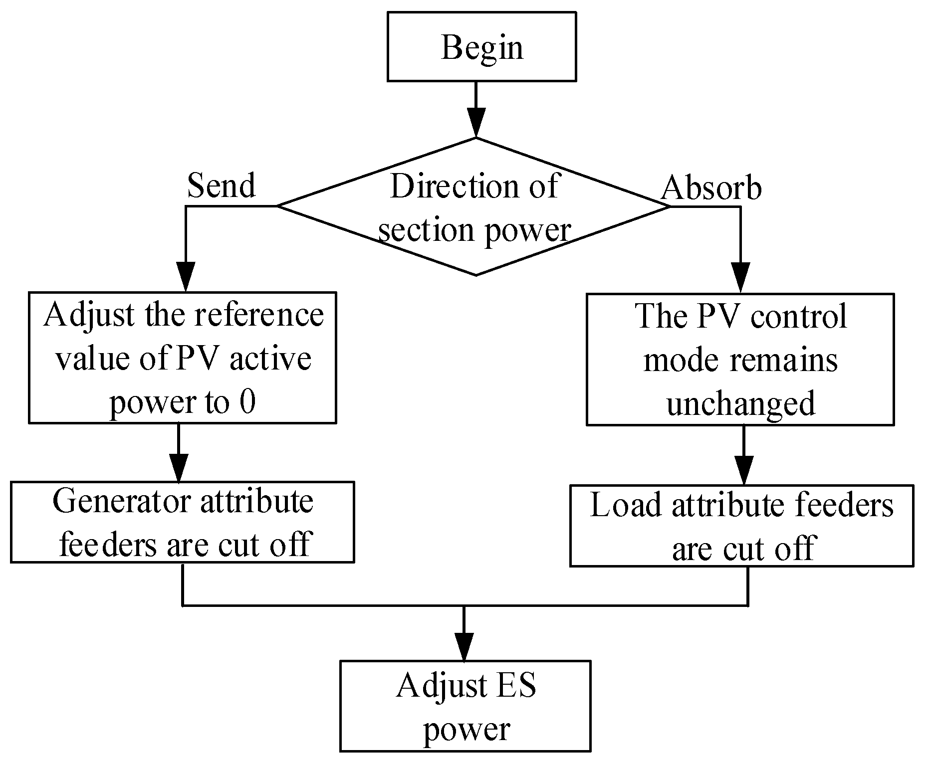
If the exchange power between the regional distribution network and the main grid is large, the stable operation of the island cannot be controlled only by ES and PV. To achieve the goal of power balance, it is necessary to adopt a generator-tripping or load-shedding strategy, as shown in
Figure 3.
To implement the strategy, this paper treats each feeder as a generator or load. Due to the large number of small hydropower and load, it is difficult to collect real-time power data for each small hydropower or load. Additionally, it is almost impossible to accurately cut off each load or small hydropower. Therefore, this paper regards each feeder as a load or generator according to its real-time power. By operating the outlet breaker of each feeder, the strategy of generator tripping or load shedding is realized. Although this scheme may accidentally switch off some loads or generators, it can ensure an uninterrupted power supply for important loads in the area. It can also accelerate the re-connection of the island and improve the power supply reliability of the regional distributed network.
According to the load level, the feeder is divided into primary, secondary, and tertiary. The load in the primary feeder is the most important, and power supply interruption will cause casualties or significant losses.
The island stability control strategy combining regulation and tripping, shown in
Figure 3, takes four steps as follows.
The first step is to obtain the real-time power direction of each feeder and determine the attributes of each feeder.
The second step is to determine the cutting power of the generator or load based on the section power and power regulation limit of PV. If the regional distributed network absorbs power from the main grid before the island, it is necessary to cut off the feeders of the load attribute. Otherwise, it is necessary to cut off the feeder of the generator attribute. The power of the generator tripping or load shedding is shown in Equations (7) and (8).
The third step is to select the appropriate feeder from all feeders for the cutting operation. The three principles should be followed.
Principle 1: According to the importance level of the feeder, low-level feeders are preferentially selected to be cut off.
Principle 2: The total power
PC to be cut off should be minimum. For the same important level, since all generators and loads in the feeder are simultaneously cut off, the cut-off power
PC is the total power of the load
PR and the power
PG. Its calculation equation is shown in Equation (9).
Principle 3: The number of feeders to be cut off should be minimal. After the feeder is cut off, power restoration requires manual operation, which may take a lot of time. Therefore, it is also necessary to minimize the number of cut-off feeders.
The cut-off feeders should be selected based on the above three principles. Principle 1 is necessary. Principles 2 and 3 can be appropriately chosen based on actual situations.
In order to meet Principle 3, the power of feeders of the same level is generally ranked, and feeders with high power are selected preferentially, which ensures that the number of cut feeders is minimized. However, it is difficult to select the appropriate cut feeder from two or more feeders with similar power. Therefore, a priority determination method considering a static source-load ratio has been proposed in this paper.
Firstly, the source-load ratio Rsr is calculated based on the generator and load in the feeder. For feeders with m generator nodes and n load nodes, the source-load ratio calculation is shown in Equations (10) and (11).
If
,
Else if
,
In Equations (10) and (11), SS is the generator capacity of each node, and SR is the load capacity of each node. Through the above calculation, the source-load ratio Rsr of each feeder is less than 1. The closer the source–load ratio is to 1, the more the load and generator are equivalent. The priority of this feeder is lower.
The fourth step is that the island power gap is filled by ES. Due to its ability to operate freely within the four power quadrants, ES provides smooth adaptation to island unbalanced power. After selecting the feeders to be cut off, the real-time power of each feeder is compared with the adjustable capacity of ES. If the sum of the power of one or more feeders is less than the adjustable capacity of ES, these feeders do not need to be cut off. The capacity gap can be filled by ES.
The above four steps are the implementation method of combining regulation and tripping. The stability control of the island is a dynamic process. The island stability control strategy proposed in this paper should be adjusted according to the real-time situation. Although it may lose a portion of the load, it can ensure a seamless power supply for important loads.
4. Simulation
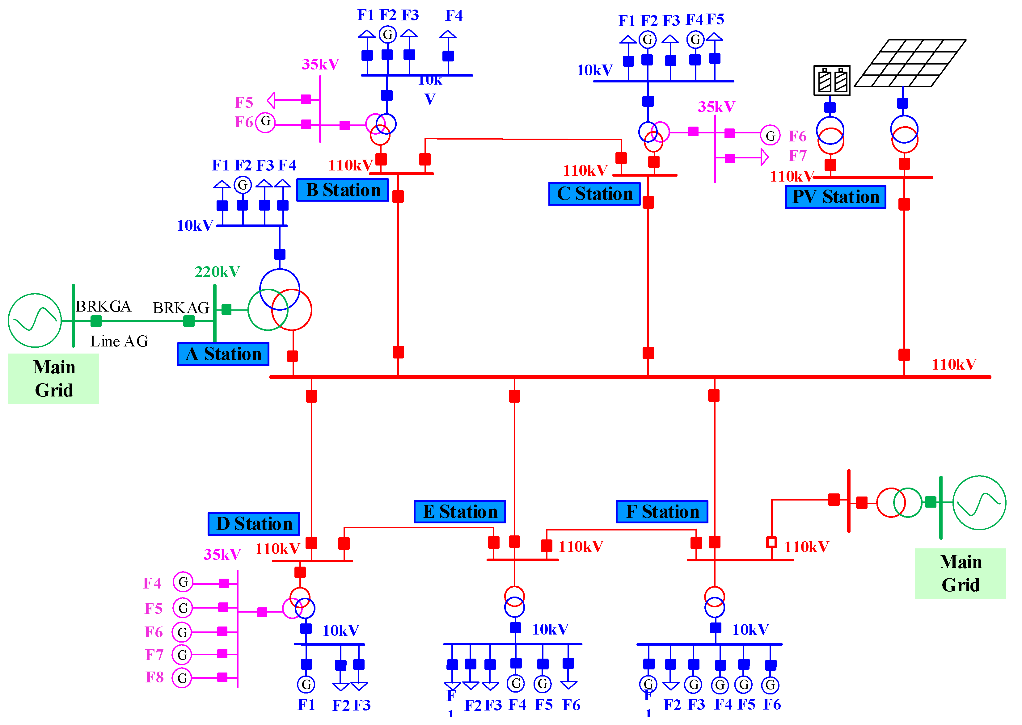
To verify the correctness of the proposed method, the project team developed a regional distributed network fault self-healing system which consists of one master device and seven slave devices. A Hardware-in-loop simulation platform based on Real-time Digital Simulation System (RTDS) was conducted as well.
The configuration scheme of the seamless fault self-healing system is shown in
Figure 4. The master device is configured in substation A to receive the data from the slave devices. The master device formulates stability control strategies based on real-time operating conditions and issues regional control commands to each slave device. The slave devices are respectively configured in 7 substations.
The simulation platform, as shown in
Figure 5, consists of a master device, seven slave devices, a set of line protection devices, a PV controller, an ES controller, and an RTDS simulation system.
The current and voltage signals simulated by RTDS are output through the GTAO board. They are amplified by power amplifiers and then sent to the Merging Units (MU) and line protection device. The MUs convert the collected voltage and current signals into sampled value (SV) messages and then transmit them to each slave device through the process layer network. Each slave device calculates the power of each feeder. The breaker position is output by the GTDO board and then sampled by the intelligent terminal.
The tripping command and circuit breaker position between the protection, slave devices, and slave devices are transmitted through Generic Object Oriented Substation Event (GOOSE) message. Then, the GOOSE messages are converted into an electrical trip command by the intelligent terminal, which is input to the RTDS through the GTDI board or output from the RTDS through the GTDO board. The information uploaded from the slave devices to the master device includes the position of each breaker (Double Point), and each branch’s power (Floating Point). The commands issued by the master device to the slave device include the island switching command, power setting command, generator tripping, and load shedding command.
The main parameters of the simulation model are shown in
Table 1.
The meaning of each curve in the simulation result is shown in
Table 2.
In the simulation, there are two modes of small hydropower: wet season and dry season. The load also has two modes: heavy load and light load. There are four working conditions that have been simulated.
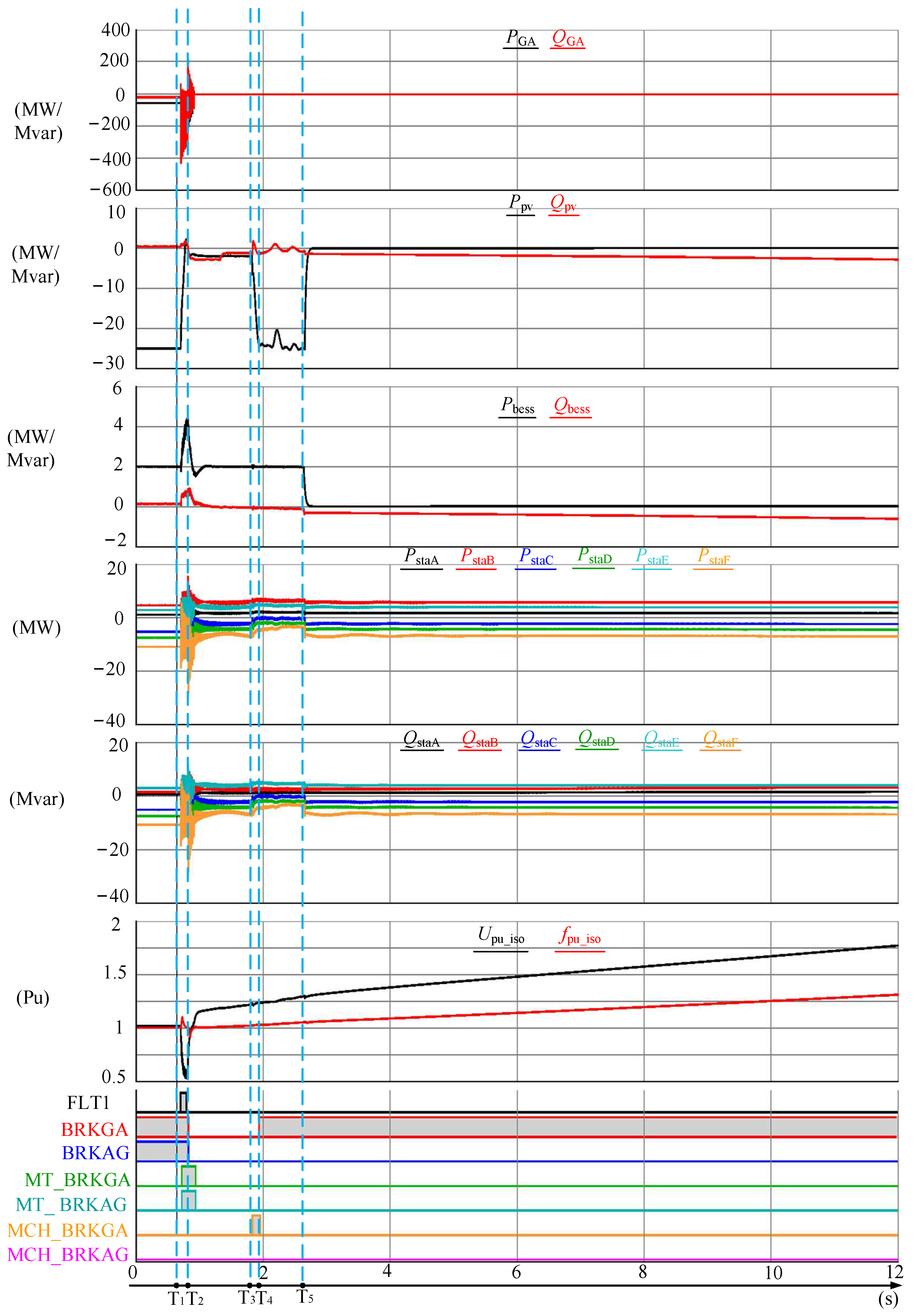
Work condition I: In the light load condition during the wet season, the island stability control strategy was not implemented.
The regional distributed network sent about 55 MW active and 19 MVar reactive power to the main grid. The simulation result is shown in
Figure 6.
Between 0 s and T1, the regional distributed network was connected to the main grid. The outpower of the PV station was 25 MW. The active output power of ES was 2 MW.
At time T1, a transient fault occurred in the tie line GA between the regional distributed network and the main grid. Voltage decreases, and frequency fluctuations occur in the regional distributed network. The PV station entered a Low Voltage Ride Through (LVRT) mode, and its power was close to zero. The active and reactive power of generators in all substations fluctuated significantly.
The relay protection devices installed on both sides of the GA line operated correctly. At time T2, the fault was isolated. The regional distributed network becomes an island. Due to the LVTR strategy of the PV controller being extended for 1 s, the PV inverters connected to the substation without any output during this period. The power of the generator gradually stabilized.
At time T3, the reclosing of protection at BRKGA operated unconditionally. At time T4, the BRKGA breaker was closed. During the period from T3 to T4, the LVRT strategy of the PV exited, and the power was raised again. The voltage and frequency offsets in the island were exacerbated. After T4, the protection at BRKAG was continuously detecting the synchronization conditions. However, the frequency and voltage of the island exceeded the set value of reclosing. The reclosing cannot operate.
At time T5, the frequency of the island exceeded the frequency protection setting value of PV or ES. The ES inverter and PV inverters were finally separated. The fault recovery of the regional distributed network failed.
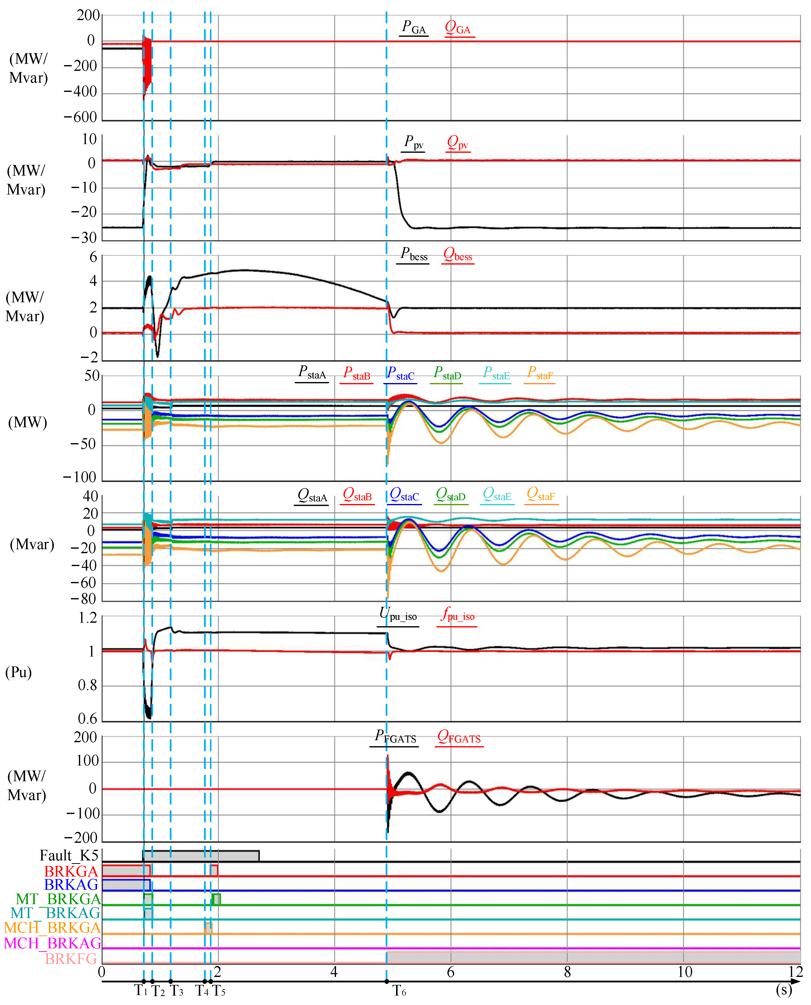
Work condition II: In the light load condition during the wet season, the island stability control strategy was implemented.
At time T
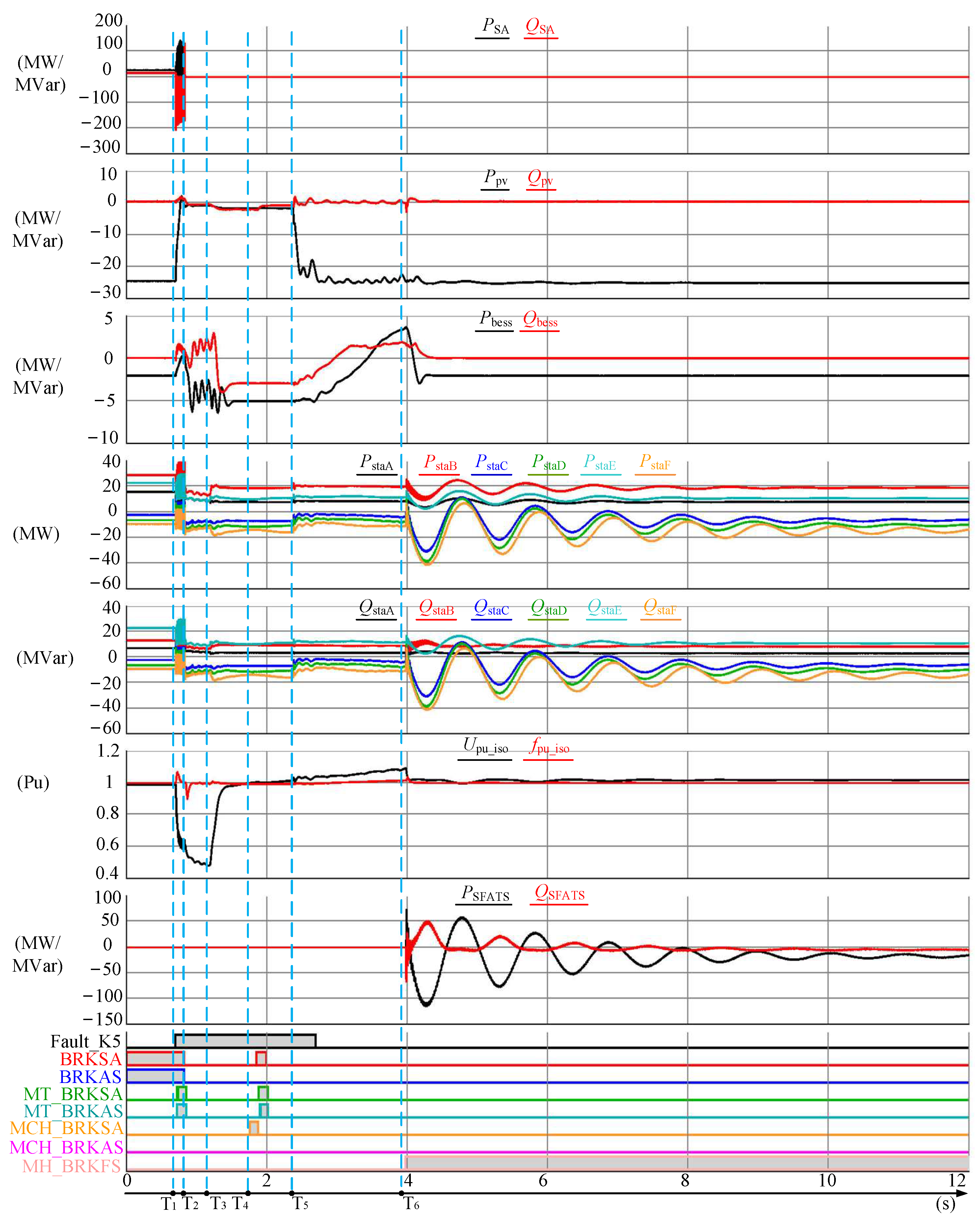
1, a permanent fault F1 occurred in the GA line. The simulation result is shown in
Figure 7. The simulation result from T
1 to T
2 is the same as that of condition I, so it will not be repeated.
At time T2, the regional distributed network became an island. The master device evaluated the stability control ability and developed a stability control strategy that combines regulation and tripping. According to the real-time power of each feeder, the feeders that should be cut off were determined, and the cut-off command was sent to the slave devices by the master device. Additionally, the island control mode switching command was sent to the PV and ES controllers. After receiving the command, the PV controllers switched into the manual control mode and set the active reference value to 0. The ES controller switched into the island control mode as well. At time T3, several generator attribute feeders were cut off, with a total capacity of about 30 MW. The power of the island was balanced. During T3 to T4, the island operated stably, and the frequency and voltage remained stable.
After time T4, the island began to be re-connected to the main grid. Firstly, the protection installed at the BRKGA breaker unconditionally reclosed the breaker. However, the BRKGA breaker failed to be reclosed due to the permanent fault. At time T5, the protection at the BRKGA breaker accelerated to trip the breaker.
After receiving the reclosing failure message, the master device determined that a permanent fault had occurred on the line. The master device also sent a standby automatic switching command to the slave device at the F station. After receiving the command, the slave device at station F enabled the standby automatic switching function. At time T6, the simultaneous conditions were met, the BRKFG breaker was closed, and the regional distributed network was re-connected to the main grid. The total time from the occurrence of a fault to the restoration of grid connection in the regional distributed network is about 4180 ms.
Work condition III: In the heavy load condition during the wet season, the island stability control strategy was implemented.
The regional distributed network sent about 8 MW active and 0.5 MVar reactive power to the main grid. The simulation result is shown in
Figure 8.
The power exchanged between the regional distributed network and the main grid was small. After the island, stable operation can be maintained only by the power regulation of ES and PV.
The simulation result from T1 to T2 is the same as that of condition I. At time T2, the regional distributed network becomes an island. By adjusting the output power of PV and ES, the stable operation of the island can be maintained without the measure of generator tripping or load shedding. In the initial stage of the island, the PV had no power output due to LVRT. The ES maximized the power output to maintain the stable operation of the island.
At time T3, the power output of the PV resumed, and the voltage and frequency of the island increased. The ES reduced power output. At time T4, the island was connected to the main grid due to the operation of reclosing.
The total time from the occurrence of a fault to the restoration of the grid connection was about 3100 ms.
Work condition IV: In the heavy load condition during the dry season, the island stability control strategy was implemented.
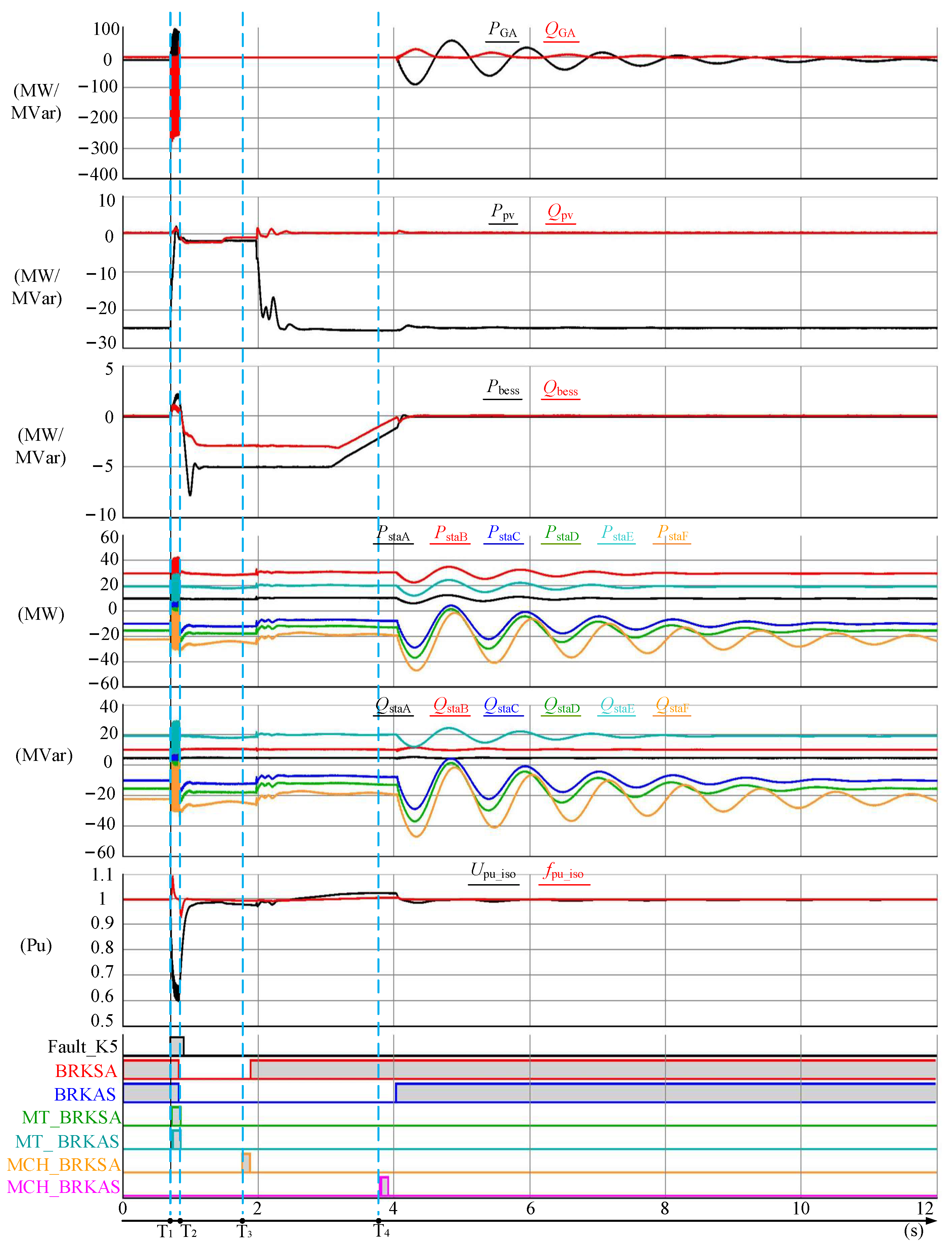
The regional distributed network absorbed about 27 MW active power and 16 MVar reactive power from the main grid. The simulation result is shown in
Figure 9. After island, it was necessary to cut off the feeder lines with load attribute in order to maintain stable operation.
At time T1, a permanent fault F1 occurred in the GA line. At time T2, the regional distributed network became an island. After that, the lack of generator power led to the maximum power output of ES. At time T3, the feeder of the load attribute was cut off by the master device. The frequency and voltage of the island raised. At time T4, the reclosing operation of protection was unsuccessful due to the permanent fault. At time T5, the power of the PV is restored. At time T6, the BRKFG breaker was closed by the master device, and the grid connection of the regional distributed network resumed.
The total time from the occurrence of a fault to the restoration of the grid connection is about 3290 ms.
