Review

Removable, Reconfigurable, and Sustainable Steel Structures: A State-of-the-Art Review of Clamp-Based Steel Connections

1
Department of Construction and Manufacturing Engineering, Universidad Nacional de Educación a Distancia (UNED), C/Juan del Rosal 12, 28040 Madrid, Spain
2
Department of Materials Engineering, Applied Mechanics and Construction, School of Industrial Engineering, University of Vigo, 36208 Vigo, Spain
*
Author to whom correspondence should be addressed.
Sustainability 2023, 15(10), 7808; https://doi.org/10.3390/su15107808
Submission received: 21 March 2023 / Revised: 3 May 2023 / Accepted: 4 May 2023 / Published: 10 May 2023

Abstract

:
In this review paper, first of all, an analysis of the circular economy and its application to steel structures is carried out. It highlights the need to apply the philosophy of Design for Deconstruction or Design for Disassembly (DfD) from the conception of the structure so that it can be truly reconfigurable. Then, a brief review of the different types of connections for steel structures is conducted, comparing the level of research and development of each of them and the degree of reconfiguration that is possible to obtain. Subsequently, the article focuses on the type of connection using clamps, a key point of this work and on which, to date, there are no state-of-the-art studies. It describes the types of clamps, their principle of operation, the types of connections developed with them, and the results of the different investigations that allow for calculating these types of connections. A summary is also given of how these connection types work according to the geometrical characteristics of the clamp and the bolt so that this review work can serve as a driver for the widespread use of clamp-based connections by researchers and engineers in the design and manufacturing of demountable and reconfigurable steel structures. Finally, some conclusions are given, indicating the advantages and disadvantages of this connection system and future lines of research.

1. Introduction

Construction and demolition waste represents the largest volume, accounting for approximately one-third of all waste produced annually in the European Union. Although steel structures can be recycled, this solution leaves a significant ecological footprint as there is a significant expenditure of energy and use of resources in this transformation. Within the framework of a circular economy (repair-reuse-recycle), it is desirable to maximize the available resources, being more advantageous for the economy and the environment to reuse rather than recycle. In the construction sector and industrial production processes, greater sustainability is required and should be materialized, for example, in a drastic reduction in the generation of waste due to the structures, looking for their systematic reuse within the framework of a circular economy oriented towards ecological transition.
In this state-of-the-art review, first, an analysis of the ecological transition and sustainability policies applicable to steel structures is carried out, especially concerning the circular economy as applied to industrial facilities, one of the areas where steel structures have a shorter useful life. The types of connections currently used in steel structures are also reviewed, focusing at the end on those that provide solutions that allow for the creation of fully removable, reconfigurable, and reusable steel structures. This review defines the types of steel structures that are fully reconfigurable and reusable, as many times as necessary, as sustainable steel structures.
Today, there is a clear general policy of advancing on the path of ecological transition using materials and processes that make it possible to generate the least possible environmental impact through lower energy and raw material consumption, as well as reduced CO2 emissions. Among these policies is the circular economy (Figure 1). In a circular economy, manufactured products are kept in use for as long as possible through closed circuits: (1) repair, (2) reuse, and (3) recycling, thus avoiding manufacturing new products from raw materials. In a circular economy, the preference is always for repair over reuse and reuse over recycle since, as the approach goes from repairing to recycling, the energy consumption increases.

1.1. The Circular Economy According to European and World Policies

Multiple European and global directives, policies, and recommendations highlight and promote a circular economy. Among these are the following:
(a) The resolution adopted by the United Nations General Assembly on 25 September 2015, 70/1, is titled “Transforming our world: the 2030 Agenda for Sustainable Development. United Nations.” [1]. Within its “Objective 12. Ensure sustainable consumption and production patterns”, point 12.5 specifies the requirement to “by 2030, substantially reduce waste generation through prevention, reduction, recycling, and reuse”.
(b) Regulation (EU) 2020/852 of the European Parliament and of the Council of 18 June 2020 [2] states in article 13: “Substantial contribution to the transition to a circular economy. (1) An economic activity shall qualify as contributing substantially to the transition to a circular economy, including waste prevention, reuse and recycling, where that activity: (b) increases the durability, reparability, upgradability, or reusability of products, in particular in designing and manufacturing activities” and “(e) prolongs the use of products, including through reuse, design for longevity, repurposing, disassembly, remanufacturing, upgrades and repair, and sharing products”.
(c) The European Commission, Directorate-General for Environment document titled “Impacts of circular economy policies on the labor market: final report and annexes, 2018” is also relevant [3]. Point 4, titled “Circular economy activities in different sectors” includes Section 4.4, c “Construction sector”. Section 4.4.3, “Circular strategies for the construction sector”, states “In the design phase, it is important that buildings are made in such a way that they can easily be remodeled, retrofitted, expanded, or disassembled… At the end-of-line stage, deconstruction is preferred over demolition as this enables the reuse of materials in the construction of new buildings”.
(d) The document “Circular economy, principles for buildings design” by the European Commission, dated 21 February 2020 and created by GROW.DDG1. C.4 is also of interest. [4]. Point 3.2 “Target group 2: Design teams” (engineering and architecture of buildings) is relevant to circular economies. Point 10 also states to “Promote and ensure reversibility and adaptability of the building. The periods between changes of use, renovation, or reconstruction are becoming shorter and shorter”.
(e) The report “Towards a circular economy” from the Ellen MacArthur Foundation [5], a world reference foundation in circular economics, indicates that: “First, at its core, a circular economy aims to ‘design out’ waste. Waste does not exist—products are designed and optimized for a cycle of disassembly and reuse. These tight component and product cycles define the circular economy and set it apart from disposal and even recycling where large amounts of embedded energy and labor are lost”.
Based on all these European and global recommendations, directives, and policies, using the circular economy is one of the main paths to advance in the ecological transition to achieve environmental protection and conservation. Within the circular economy, it is indicated that repair or reuse is always better than recycling, with recycling [6] being the last option if repair or reuse is impossible.

1.2. The Circular Economy Applied to Steel Structures

As indicated in the previous section, within the areas where the circular economy [7,8,9,10] can be applied (prioritizing reuse over recycling) are structures, especially those made of steel, whose useful life is less than 50 years. When these structures are no longer functional, it is necessary to scrap them, generating a large amount of waste. As was indicated by Kibert et al. [11] that waste from building demolition (partial demolition for renovation or total demolition for building removal) represents 30% to 50% of total waste in most industrialized countries. Construction and demolition waste is the largest source of waste by volume in the European Union, accounting for one-third of all waste produced annually [12]. Among the main components of these constructions are the structures.
Although steel structures can be recycled, this means the expenditure of energy, as well as CO2 emissions. For example, according to the research by Brütting et al. [13] on multiple combinations of truss structures, those made from reused elements have up to 56% lower environmental impact compared to minimal-weight solutions from new steel elements (from recycled steel). On the other hand, Eckelman et al. [14] showed how the reuse of building elements three or more times according to their design reduces impacts by an average value of between 60% and 70%, depending on the configuration of the building and the impact category. It is precisely on the reuse of steel structures that more work remains to be done to determine the right way toward an optimal ecological transition. For example, the results of the work of Sansom et al. [15] on steel structures in the UK can be mentioned, where it is indicated that, on average, 91% is recycled, and only 5% is reused, which indicates that in general there is still significant work to do to assure that the percentage of reused steel structures increases considerably.

1.3. Design for Deconstruction (DfD)

In order to achieve the actual substantial reuse of steel structures, the initial design must be conceived for the disassembly and reuse of the products [16,17,18,19]. The “Design for Deconstruction” or “Design for Disassembly” (DfD) for steel structures in particular, and construction in general, is today one of the “hot topics” where intensive research and work is being carried out. In this area, one can mention, for example, the work of Tingley et al. [20], where methodologies for LCA studies were established that include the design for deconstruction within buildings to facilitate future reuse. Akbarnezhad et al. [21] proposed a methodology to evaluate and compare the impact of different alternative deconstruction strategies on the cost, energy use, and carbon footprint of buildings based on Building Information Model (BIM) tools. Basta et al. [22] show that design for deconstruction is one of the most effective end-of-life design scenarios for reversible buildings. Charef et al. [23], in a state-of-the-art review, present a detailed map of the barriers that would facilitate the architecture, engineering, and construction sector to develop strategies to overcome the current obstacles to a circular economy, among which Design for Deconstruction would be the starting point. Cottafava et al. [24] address the gap between the environmental impact of construction and aspects related to design for deconstruction. Additionally, more general works, such as that of O’Grady et al. [25], focus on proposing new indices based on the circular economy for the built environment, design for deconstruction, and resilience. In general, all these works, which are only a small number of the existing ones on this topic, highlight the great importance of the preliminary design of buildings and their structures, thinking about their future disassembly and reuse in order to achieve the objective of a circular economy, where the priority is reuse and not recycling.

1.4. Industrial Facilities and Associated Steel Structures

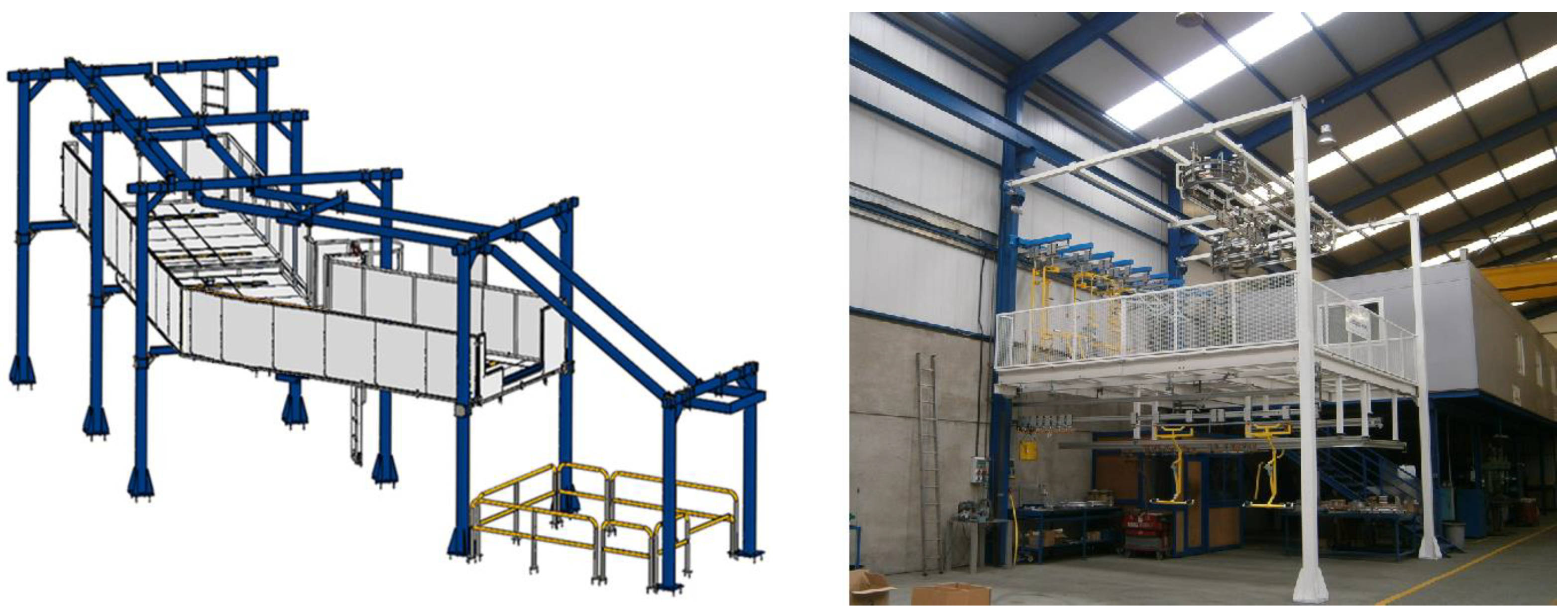
The industrial sector is one of the sectors with intensive use of steel structures and a shorter useful life compared to the building or infrastructure sector. Industrial facilities and their production processes are dynamic environments that must adapt to the demands of manufacturing processes, so layout changes are frequent over time. Thus, during the life cycle of a plant, it is very common to install new facilities and/or reconfigure existing ones. In sectors such as the automotive, pharmaceutical, or textile industries, the layouts are reconfigured and changed on average at intervals of less than 10 years [26]. For example, in the automotive sector, changing a vehicle model or restyling implies a layout change, which is currently carried out at intervals of 7 to 8 years. However, these intervals are becoming shorter in industrial conditions of high competitiveness and oriented to maximum productivity. These changes usually entail modifying the support structures of installations and machinery (Figure 2).
In the industrial sector, new solutions are required so that structures can be reused almost indefinitely, thus promoting the principles of a circular economy that is environmentally friendly (sustainable) and more efficient (reducing the need for new investments).
In particular, in industrial facilities and their support structures, there are the following issues: (a) Industrial machinery and logistics facilities that are assembled inside industrial buildings, such as roller paths, conveyors, belts, manipulators, etc., are always supported by structures suitable for such equipment. When these facilities or machinery are of considerable size (loads greater than 500 kg/m), these structures are made with standard steel profiles with classic welded or bolted connections. (b) Layout changes for new products in the industry are becoming more frequent, and it is desired that these require less investment. (c) The types of support structures with standard profiles used today in industrial production processes are not reconfigurable or reusable since they are made with welded or bolted connections. Bolted connections can be disassembled, but previous work must always be carried out on the profiles—for example, plate welding, stiffening and drilling of profiles, etc.—making it impossible to use them in another new and different structure since they have a configuration that is valid only for a very specific purpose. For this reason, in almost all cases, it is more expensive to reconfigure the structure than to build a new one, leading to the choice to scrap them when the manufacturing process layout is changed, even though these structures have not deteriorated.

1.5. Advantages and Disadvantages of Sustainable Steel Structures

In the use of dismountable and reconfigurable systems, the more easily reconfigurable the system is, the more elements can be reused. In this way, the structure is more environmentally friendly, since it would allow for the reuse of the vast majority of the components and avoid generating a large amount of scrap with the consequent savings in transformation energy, raw material costs, and CO2 emissions. However, it must be taken into account that the use of reconfigurable structures also has associated disadvantages, such as the handling, storage, and stock management of the different components, once disassembled and while they are not used in another new configuration. Further, as mentioned below, the connection types that are easiest to reconfigure are novel systems that are not yet widely used. On the one hand, this means that they have a low degree of industrialization and, therefore, higher costs, and on the other hand, the level of studies and developments carried out is very low.
This work aims to briefly review the different types of connections used in steel structures and analyze them from the point of view of their disassembling and reconfiguring ability. After this review, the main value of the paper is given, focusing on gathering all information about connections based on clamps, a priori one of the most promising solutions to obtain fully dismountable and reconfigurable structures for I-shaped profiles. For this purpose, the types of clamps, their working principle, connections developed with them, and the research results that allow for calculating these connection types will be described. A summary of how this connection works according to the geometric characteristics of the clamp and the bolt is also given so that this review work can serve as a baseline for the use of clamp-based connections by engineers in the design and manufacturing of demountable and reconfigurable structures, as well as to encourage other researchers to deepen insight in their mechanical behavior.

2. Non-Reconfigurable Steel Connections

The critical point for a structure to be dismountable and reconfigurable is the type of connections used. Among the commonly employed and that are either not removable or difficult to reconfigure are the following.

2.1. Welded Connections

Welding is one of the methods most used for building steel structures and infrastructures, especially from standard steel profiles [27,28]. Multiple standards about this type of connection [29,30,31,32] and research work in the literature [33,34,35,36,37,38,39] can be found. Welded connections cannot be disassembled; thus, the only solution is cutting them with a torch and scraping them.

2.2. Bolted Connections

Another currently most commonly used connection for building steel structures and infrastructures, especially from standard steel profiles, is bolted connections [27,28]. A wide variety of standards can also be found on this type of connection [29,30,31,32] and research in the existing literature [33,34,35,40,41,42,43]. Bolted connections can be disassembled; however, prior operations must be carried out on the profiles, for example, welding of end plates, stiffening of the profiles, drilling of profiles, etc. (Figure 3). Due to this preliminary work, the steel members or profiles can only be used for their initial purpose, meaning that their reuse is minimal since each element is manufactured to measure and has a configuration valid only for a very specific purpose. Therefore, when this type of bolted structures needs to be reconfigured, the reconfiguration is more expensive than manufacturing a new structure, so in most cases, they are scrapped when they need to be modified.

2.3. Connections Using Blind Bolts for Square or Rectangular Tubular Profiles

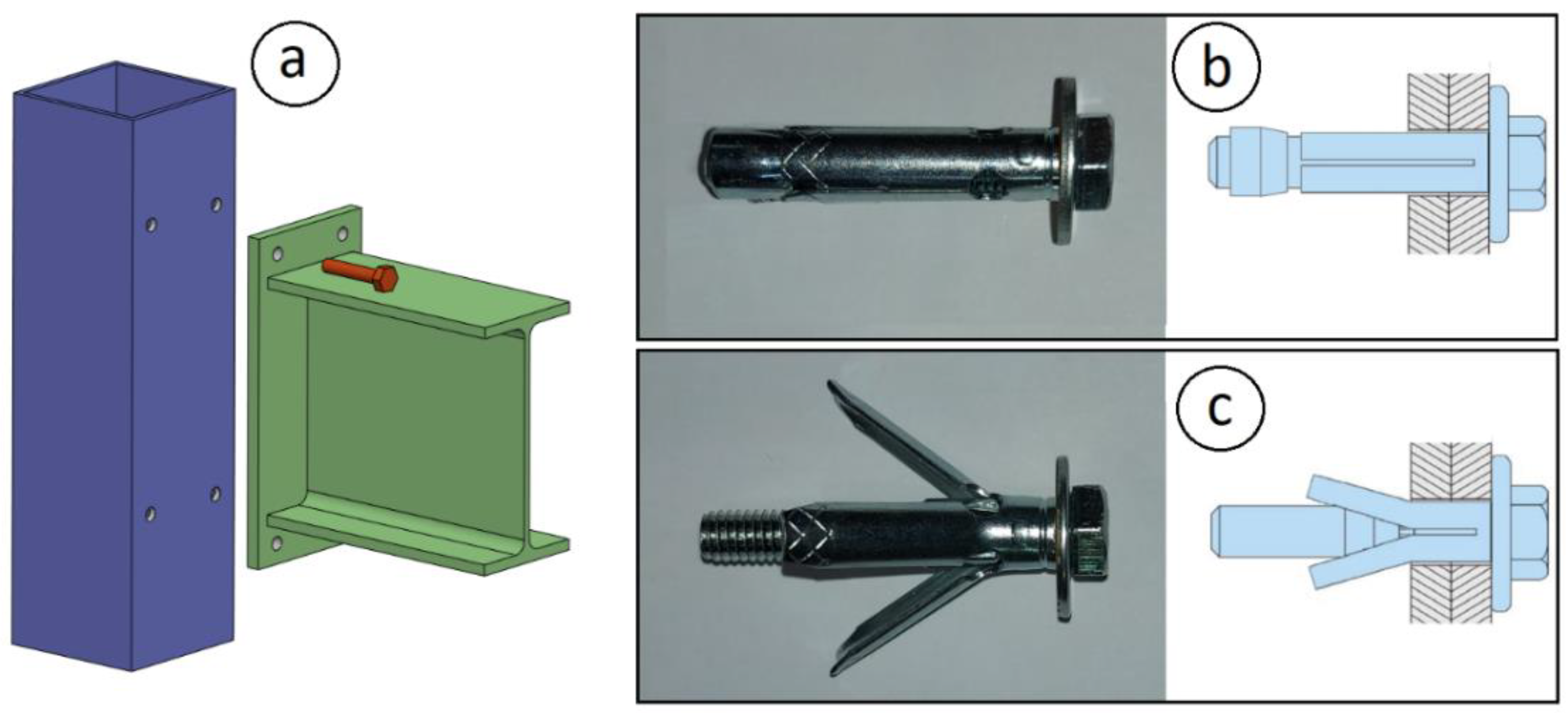
Currently, there are removable connection systems for square tubular profiles, such as connections using blind bolts, for example, the “Hollo-bolt” [44] or the “Boxbolt” [45]. These systems allow for the assembly of structures from square or rectangular tubes without the need to weld them or use welded plates or threaded holes (Figure 4). However, the drawback is that this type of connection requires drilling in the column and using a head plate in the beams, so they are challenging to reconfigure, as in the case of classic bolted structures. Concerning existing research work on this type of connection, Cabrera et al. [46] carried out a state-of-the-art study describing the procedures used for experimental testing and the failure modes produced, also addressing the development of analytical models for their mechanical analysis. Further, Cabrera et al. [47] performed an experimental and numerical analysis of the preload effect on this type of connection. Wang et al. [48] investigated the behavior of the bolt when used in connections that support bending moments. Another work was carried out by Lee et al. [49], presenting the results of experimental tests with T-stub connections with blind bolts to hollow section columns in the tension and compression regions under static loading. Yang et al. [50] presented an experimental study on the seismic performance of modular steel construction beam-to-beam combined side column joints with blind bolted connections.

2.4. Connections Using Perforated Profiles

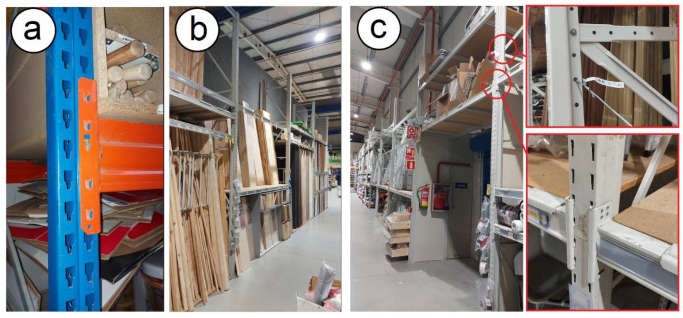
Another connection solution in steel structures is to use continuously perforated columns, to which the beams are joined by quick hooks made using tabs that protrude at the ends (see Figure 5). This type of connection is commonly used in storage racks, which can be the load-bearing structure. This type of connection allows for the easy disassembly of the whole structure and the reconfiguration of the heights of the beams, but it is conditioned to the length of the original beam, and this cannot be changed without replacing those beams with others of the required length. The main limitation of this type of connection is that it is designed for use in racking systems. Several research works have been carried out in this domain, such as by Abdel-Jaber et al. [51], who conducted a theoretical and experimental investigation of underbalanced rack structures. In Galeotti et al. [52], the seismic response of this type of rack structure was studied, while Elias et al. [53] reported on an experimental investigation of the behavior of racking uprights under axial compression. Ng et al. [54] showed several methods of restraining progressive collapse in rack structures. Godley and Beale [55] researched the effects of the looseness of bracing components in the cross-aisle direction on the ultimate load-carrying capacity of pallet rack frames. Sajja et al. [56] investigated the shear stiffness of pallet rack upright frames. Abdel-Jaber et al. [57] conducted a numerical study on semi-rigid racking frames under sway.

2.5. Connections Using Bolts with Removable Brackets

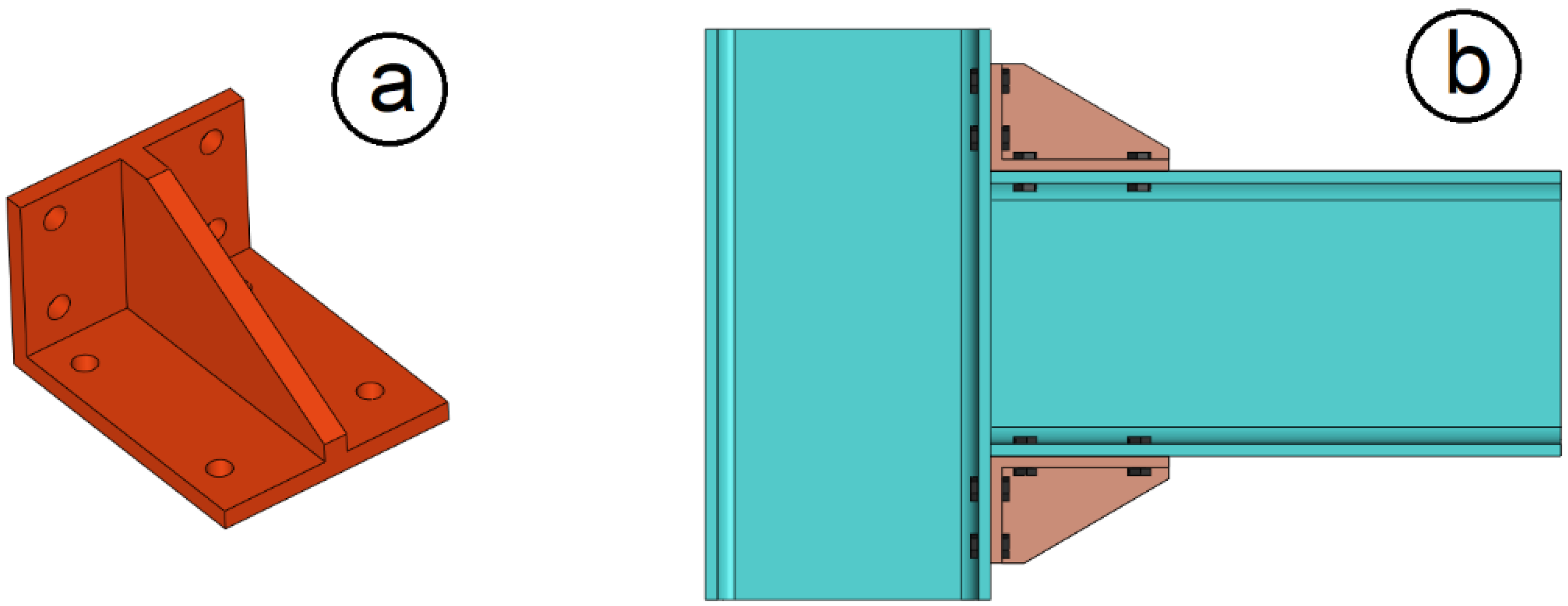
Classic bolted connections are removable but challenging to reconfigure, primarily because the beams commonly have welded end plates, usually with brackets and drills that make them impossible to reconfigure. Currently, solutions with removable brackets allow for a greater level of reconfiguration, but it is always necessary to drill the beams and columns (Figure 6). Therefore, this type of connection, while allowing for a certain degree of reconfiguration, does not allow for total reconfiguration and is more expensive than the classic bolted solution. Several research works have also been carried out on this type of connection, such as those by Reinosa et al. [58], Abar et al. [59], and Abar et al. [60].

3. Removable and Reconfigurable Steel Connections

Among the removable and reconfigurable steel connections, the following can be mentioned (this group also includes clamp-based connections, but a separate section will be dedicated to them since they are the main objective of this state-of-the-art review).

3.1. Quick Connections for Round Tubes

Among the connection systems for building removable and reconfigurable structures are those used for assembling large scaffolding from round tubes. Two types of such systems can be distinguished:
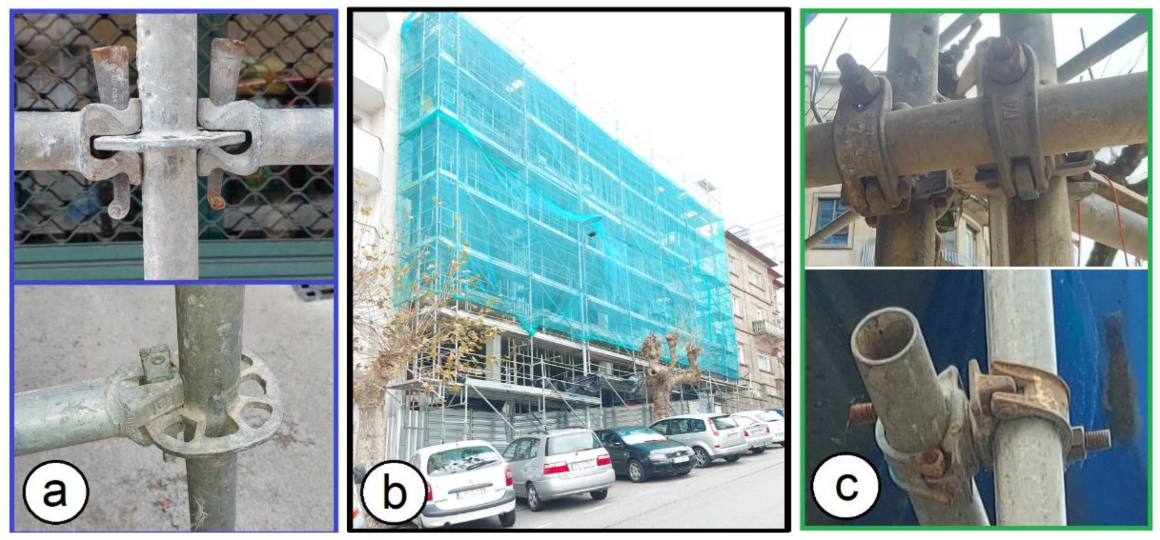
(a) Scaffolding made through disk locks, which allow for a certain degree of freedom in the assembly of the structures, although they are always limited to the heights at which the ring locks are located in the columns and limited to the length of the tubes of the horizontal and diagonal beams with their ends prepared for anchoring in the ring lock (see Figure 7). Various studies have been carried out on this type of structural system, such as those by Pieńko et al. [61], where experimental tests were carried out on ring lock-type scaffold connections. Zheng et al. [62] investigated the moment-rotation behavior of disk-lock and cuplok tubular steel scaffold connections with different configurations. Peng et al. [63] investigated load capacities and failure modes in various configurations based on experimental tests supplemented with structural analyses. Later, Peng et al. [64] investigated the stability of structures made using scaffolding systems under static load, depending on whether or not diagonals were used. Further, Abdel-Jaber et al. [65] showed the influence of incorrect scaffold foundations on the stresses in the elements. Abdel-Jaber et al. [66] conducted experimental and theoretical investigations of spigot connections under cyclic loading.
(b) Scaffolding made with quick round tube couplers, which allow for greater versatility in the building of the structures, not requiring any prior operation on the tubes and therefore being fully reconfigurable (see Figure 7b). In these types of structures, state-of-the-art reviews have been carried out, such as the one by Beale [67] or Abdel-Jaber et al. [68], where the properties of scaffolding connections and accessories under cyclical loads were studied. Prabhakaran et al. [69] presented the analysis of scaffolds with connections containing looseness. Abdel-Jaber et al. [70] showed an experimental study into the behavior of tube and fitting scaffold structures under cyclic side and vertical loads. Abdel-Jaber et al. [71] researched a cyclic loading applied to sleeve couplers for tube and fitting scaffolds. The problem with these structures is that they are only valid for scaffolding or similar structures due to their configuration and the type of profile used (round tube).

3.2. Connection of I-Type Profiles by a Collar Connection

The collar connection is a system that allows for a removable connection without the need to carry out previous operations on the columns, although it does require previous operations on the beams’ end. This type of connection is removable and reconfigurable at height, although it would always be necessary to carry out previous operations on the beams if different lengths are required when reused, so it is not actually fully reconfigurable. Among the studies performed on this type of connection are the study by Hosseini et al. [72], which is a numerical study of the rigid steel collar connection subjected to cyclical loads; the work of Rezaeian et al. [73] studying the seismic behavior of rigid connection utilizing a “connection ConXL”-type collar in box pillars not filled with concrete; and the work of Yang et al. [74], who carried out a numerical study of the seismic behavior of the biaxial moment connection using a collar of the “connection ConXL” type.

3.3. Connection with Clamps for Square or Rectangular Tubular Profiles

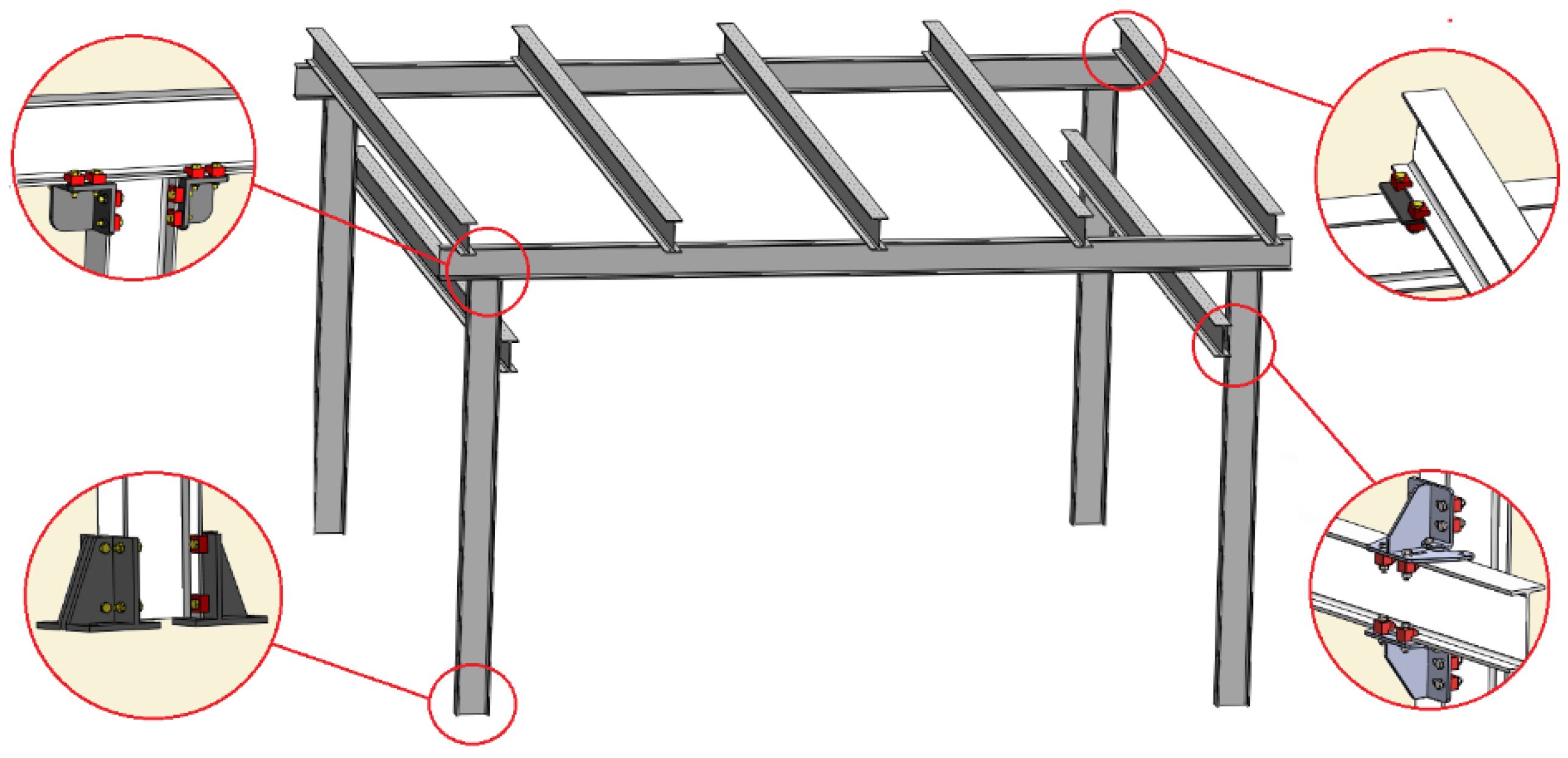
The use of clamps and bolts makes it possible to obtain a wide variety of connections between steel beams and rectangular or square section columns, leading to entirely removable and reconfigurable tubular structures. Figure 8 shows the following possible connections: (a) transverse connection between beams, (b) beam-to-column connection, (c) removable base system for square or rectangular section columns, and (d) lateral connection of beams at any angle.
Some connections mentioned above are already used for secondary beams in industrial structures, such as the transverse connection between beams. The joining systems based on the use of girder clamps are not commonly used to manufacture structures with steel profiles due to, among other reasons, the following: (a) there is a significant lack of studies, tests, publications, and further research regarding their mechanical behavior; (b) this type of connection is not included in any standard that facilitates its use by technicians who design structures; and (c) some of the required connections solutions are still pending further technical development to cover all the possible connection needs. Therefore, the main drawback with this type of connection is that more studies, developments, and tests are necessary to ensure this connection can be used more extensively.

4. Clamp-Based Connections for Steel Structures from I-Type Profiles

For standard profiles such as hot-rolled I-type profiles, clamp-based connections are one of the most promising technologies for designing and manufacturing demountable and reconfigurable structures (Figure 9). These connections do not require prior preparation of the profile, such as drilling or welding end plates, except cutting it to size. Therefore, when disassembly of the structure is necessary, all the elements are fully reusable.
After describing the different joining systems for steel structures and before analyzing clamp-based connections in detail, Table 1 provides a schematic summary of the different types of connections in terms of their disassembling and reconfiguring ability, level of study, and sustainability.

4.1. Types of Clamps

Currently, many girder clamps models are on the market, and some are equivalent, while others are more specific or exclusive to a given commercial brand [44,75,76]. Generically, clamps can be classified into two main types (Figure 10): pivoting and flat-fitting clamps [77].
Pivoting clamps have one line of contact on one of the pieces to be joined and another line of contact on the other piece to be joined. Depending on the thicknesses of the pieces to be joined, the distance of these contact lines to the bolt varies. On the other hand, in the flat-fitting clamps, the rear part rests over its entire surface on one of the pieces to be joined, and the front part over its entire surface on the other piece to be joined. Due to the flat nature, for each thickness of the piece to be joined, a different clamp height is needed (measurement k in Figure 10a), and this height can also be achieved using an additional washer. Flat-fitting clamps can have a hole, or they can have the bolt directly incrusted.
Flat-fitting clamps have the advantage that the surface of the clamp fits against the edge of the profile flange, preventing the turning of the clamp when the bolt is tightened. In addition, when tightening is carried out, the pressure distribution is uniform. The main drawback of this clamp type is that it is necessary to use a different clamp or the corresponding additional washer for each profile flange thickness. The advantage of the pivoting clamps is that the same clamp can be adapted for different profile flange thicknesses, but the drawbacks are that the clamp can turn during tightening and the distribution of stresses on the element face to be joined is carried out on a line of contact, which generates a significant concentration of stresses in these areas.
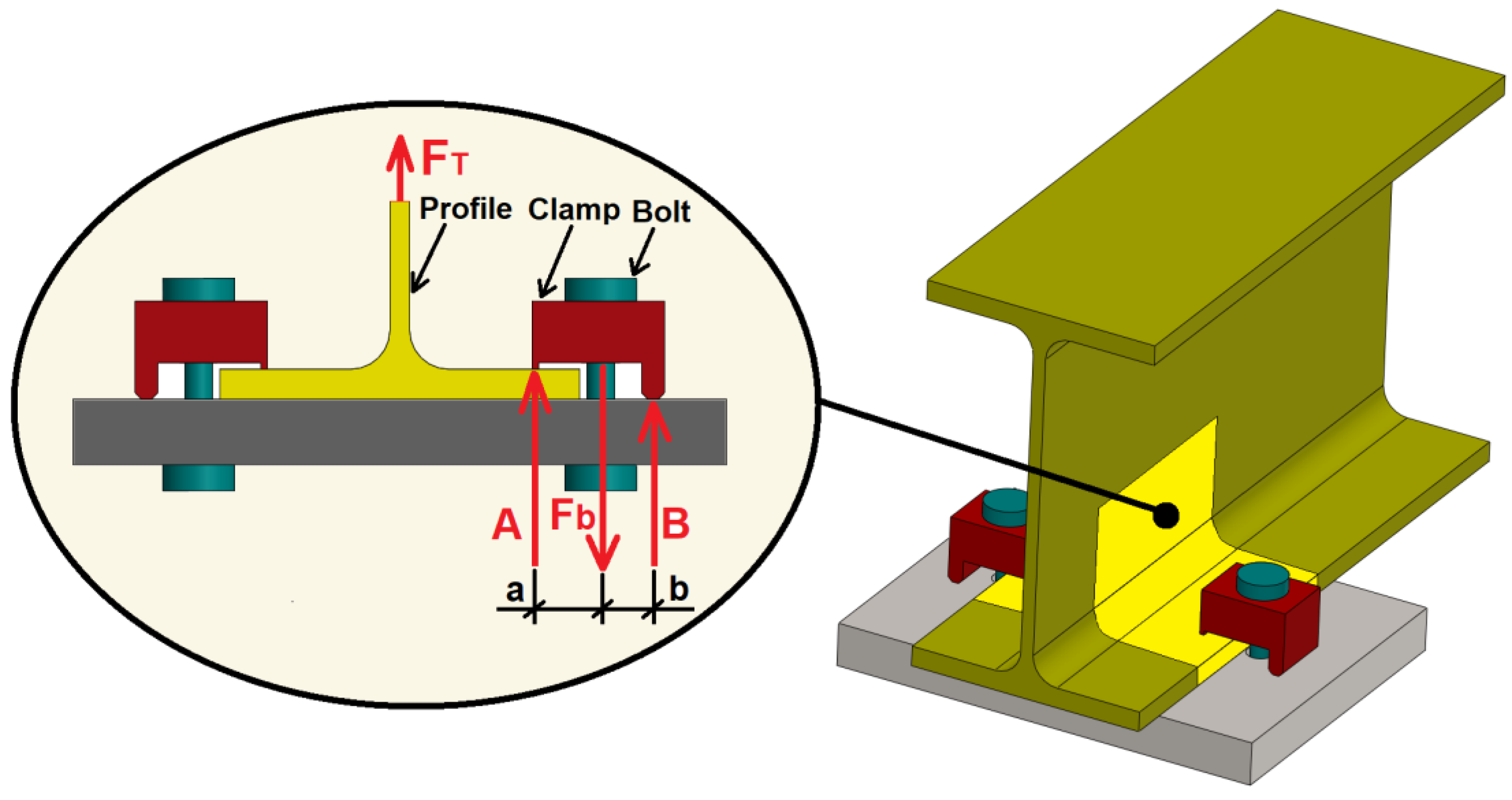
The clamps’ tightening system is based on the lever mechanism [77]. When the load is applied to the connection (Ft), it is transmitted to point A (Figure 11). The force produced at point A is supported by the bolt (Fb) and the reaction at the rear edge of the clamp (point B). The force at point A (assuming that the clamp is stiffer enough to transmit the forces between points A, B, and the bolt) is proportional to the value of the distances a and b (front and rear lever of the clamp), as well as the maximum force that the bolt can withstand. The equation that relates these forces is the following:
F b = A ( a + b ) b

4.2. Types of Connections

There are various connection solutions to manufacture removable and reconfigurable steel structures using girder clamps from I-type cross-section profiles. Among these are the following: (a) beam-to-column connection, (b) lateral connection at 90° of a transversal beam to the flanges of a column, (c) angle connection between a square tubular profile and H-type profile, (d) a removable base system for I-type section columns, and (e) transversal connection of beams. Out of the solutions mentioned above, some are already being used regularly in industrial facilities, including the transversal connection of beams, which are commonly used for anchoring and fixing rail beams, as well as in industrial buildings for secondary beams of slabs or roof purlins.
Next, the most important solutions for standard I-type profiles are further detailed.
(a) Lateral connection at 90° of a transversal beam to the flanges of a column. This system (Figure 12a) allows for the lateral connection at 90° of a transverse beam to the flanges of a column of the I-type section. Two steel brackets with several holes are used where the corresponding clamps are assembled to materialize the connection. The slotted holes in the brackets allow for the adjustment of the clamps to the flanges of different sizes of the profile to be joined.
(b) Beam-to-column connection. This system (Figure 12b) allows for the 90° connection of the end of an I-type section beam with the flange of another I-type section column. Two brackets with several slots materialize the connection, where the corresponding clamps are assembled. The slotted holes in the brackets allow for the adjustment of the clamps and their bolts to the flanges of different sizes of the profile to be joined.
(c) Removable base system for I-type section columns. This system (Figure 12c) allows for the assembly of a removable base on I-type section profiles. Four base supports are used to materialize the connection, provided with holes where the clamps will be located to allow for these supports to be joined to the profile flange. Horizontal tightening bolts are used to ensure the position of the base support on the column and allow for the transmission of lateral moments between the column and the ground (without the need to overload the clamps by shear). These horizontal tightening bolts go from the flange of the support to the edge of the flange of the profile. The connection bolts between each pair of supports allow for the connection adjustment to adapt to different column sizes.
(d) Transversal connection of beams. This system (Figure 12d) allows for the connection of the flanges of an I-type profile with the flanges of another I-type profile passing through the upper or lower part of the first profile. A steel plate materializes the connection, providing several holes where the corresponding clamps are inserted.
Detachable connections have also been made using the clamped connection technique, but with greater complexity and number of elements because this type of connection is designed to absorb significant seismic forces [78]. This system allows for the connection of the head of an I-type profile with the flanges of another I-type profile. The connection is designed to resist ordinary and intermediate moments in low and moderate seismic areas. For this purpose, two additional elements are incorporated in addition to the connection clamps with their corresponding bolts for fastening to the flanges of the profiles. The first element is some diagonals joined to the clamp plates using a hinge made with a bolt and nut. These diagonals allow for a greater bending moment to be transmitted between the beam and the column. On the other hand, the connection is also provided with tensors that increase the stiffness of the profiles against possible additional seismic stresses without the need for a fixed stiffening of the profiles between the flanges and the web.

4.3. Behavior under Axial Loads

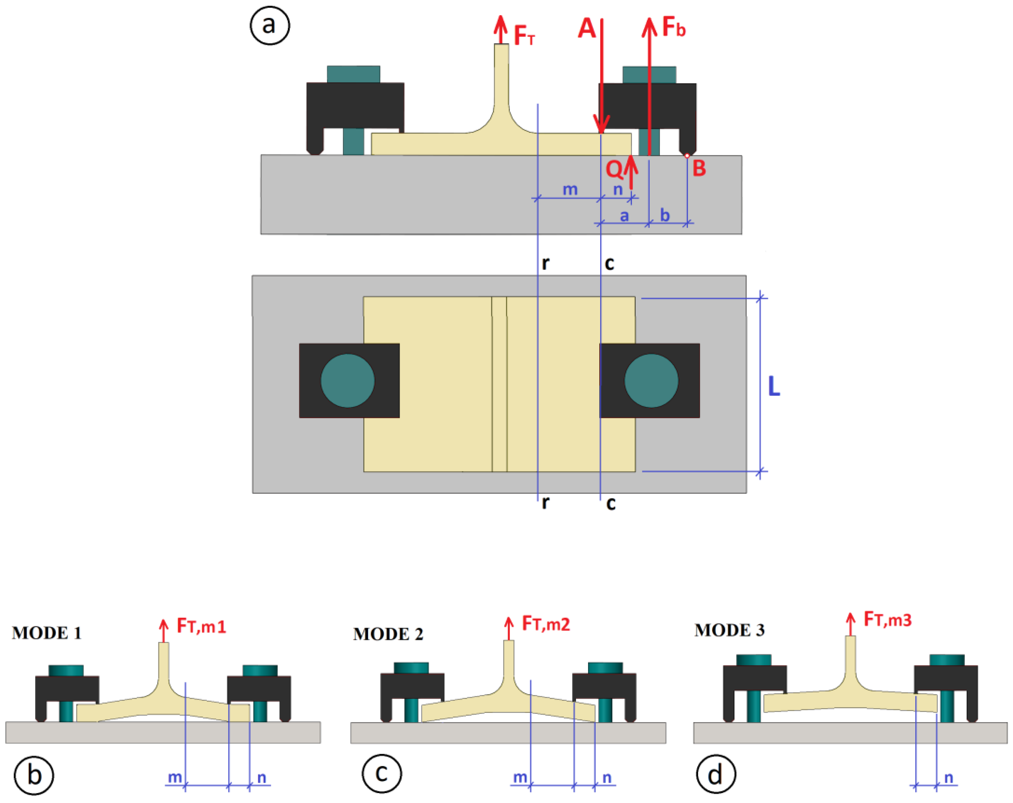
As for the clamp-based connection mechanical behavior, some research has been performed, including the work of Cabaleiro et al. [77], where an analytical model based on the T-stub methodology was proposed for the analysis of the connection according to the front and rear levers of the clamp and the geometric characteristics of the profile flange. The T-stub methodology is included in Eurocode 3 [29,30] and indicates that the bending forces to which the profile flanges in bolted connections are subjected can be calculated using an equivalent T-shaped model (Figure 13).
Similarly, this work proposed using a T-shaped model with two clamps in the flanges and the web subjected to traction. Based on this T-shaped model, an analytical approach was proposed that allows for the calculation and analysis of the clamped connection based on the measurements of the clamp levers, the geometric characteristics of the profile, and the yield strength of the material. As in the case of bolted connections, three different failure modes can be distinguished [77] (Figure 13):
Mode 1 (Flexible). Connection collapse occurs with the simultaneous yielding at the c-c line and the r-r line of the profile flange (see Figure 13b). This situation occurs because the profile flanges are deformed with a much higher value than the bolt. The failure load FT,m1 is obtained according to the following equation:
F T , m 1 = l · t 2 · f y m · γ M 0
where l is the length of the T-stub flange, t is the thickness of the T-stub flange, fy is the steel yield strength, m is the distance from the r-r line to the c-c line, and γM0 is the partial safety factor.
Mode 2 (Semi-rigid). Connection collapse is produced when yielding occurs on the r-r line of the profile flange, together with the failure of the bolt (see Figure 13c). This situation occurs because the profile flanges deform with a value equal to the bolt deformations. The failure load FT,m2 in this mode is obtained according to the following equation:
F T , m 2 , = n . F t , R d · a ( a + b ) + l · t 2 · ( f y / γ M 0 ) 4 ( m + n ) / 2
where n is the distance from the c-c line to the flange edge (see Figure 14a), Ft, Rd is the design value of resistance to the normal force of the bolt, a is the forward clamp lever, and b is the rear clamp lever.
Mode 3 (Rigid). In this failure mode, the deformation in the profile flange is small and does not reach the yield strength of the material (see Figure 13d). However, the bolt exceeds the steel yield strength, leading to its tension failure. The failure load FT,m3 in this mode follows Equation (4).
F T , m 3 = 2 F t , R d · b ( a + b )
The lowest value calculated from each failure mode should be used for the connection design.
This analytical model was validated by comparing the results with those obtained experimentally in the laboratory and with the results obtained from FEM-based simulations. Accordingly, from the proposed analytical model and depending on the value of the levers of the clamps, it was concluded that: (a) For a greater length of the front lever of the clamp, there is a decrease in the stresses at the profile, but, on the contrary, the stresses at the bolt increase. (b) For a greater length of the rear lever, maintaining the value of the front lever, the stresses at the bolt decrease. (c) The generated stresses in the flange of the profile in practice depend on the value of the front lever, because this value directly affects the point on the flange (between the edge of the flange and the web) where the clamp is supported, while the value of the length of the rear lever practically does not affect the generated stresses in the profile flange. (d) For each design of the connection with clamps, it is necessary to find, depending on the size of the profile to be used, appropriate clamp lever dimensions that provide a balance between the stresses supported by the bolt and those supported by the profile.
In subsequent work, Cabaleiro et al. [79] proposed an analytical model based on the Eurocode T-stub methodology that allows for the deformation analysis in clamp-based connections based on the preload applied to the bolts and the geometric characteristics of the clamps (mainly based on the lever dimensions). The analytical model is based on the elastic behavior of the materials and the theory of small displacements. In the study of the behavior of the connection based on the T-stub model, two working modes were differentiated:
Mode A: The deformation of the T-stub occurs without separating from the base support. In this working mode, leverage forces are developed at the ends of the profile flange, similar to classic bolted connections (see Figure 14a).
Mode B: The deformation of the T-stub occurs until it separates from the base support, but in this working mode, leverage forces are not produced because there is no contact between the profile flange and the base of the support (see Figure 14b).
For the validation of this analytical model, several laboratory tests were carried out, as well as simulations with a FE model. The results obtained with the analytical model compared to those obtained with the laboratory tests showed a difference of less than 12%. Accordingly, it was possible to conclude [79] the following: (a) The increase in the preload of the bolts leads to a significant decrease in the deformation of the connection. (b) The increase in the clamp front lever entails a decrease in the deformation of the connection. (c) The reduction of the clamp front lever implies a decrease of the elongation of the bolt and the flexion of the clamp in favor of the increase in the flexion of the profile flange. (d) The increase in the front lever implies a decrease in the bending of the profile flange and an increase in the elongation of the bolt and the bending of the clamp.

4.4. Behavior under Dynamic Loads

As indicated in the Introduction Section, one of the most promising applications of these types of clamp-based connections is in industrial structures. Nevertheless, these structures that support facilities and machinery are subjected to dynamic loads, and therefore, it is essential to evaluate their behavior under these types of actions. Among the effects of dynamic loads is fatigue, which is essential to study to understand the connection response to this phenomenon primarily based on the clamps’ main characteristics, which condition their operation, such as the lengths of the clamp levers and the preload of the bolts.
Thus, in the work of Cabaleiro et al. [80], an analysis of the fatigue behavior of this type of connection was carried out, focusing the study on the behavior of the connection depending on the size of the clamp levers and the behavior of the bolt, which is the weakest element of the connection at fatigue. Firstly, various fatigue tests were carried out in the laboratory where the rear lever had a fixed value of 17 mm, while four different values were used for the front lever. In addition, an analytical model was proposed and subsequently validated with the results of laboratory tests to calculate the number of cycles and the fatigue limit of the bolts of the clamped connection depending on the size of the rear and front clamp levers. With the proposed analytical model, the behavior of the clamped connection was analyzed as a function of different front and rear lever lengths.
According to the work of Cabaleiro et al. [80] for the case of 106 cycles (that is, unlimited life), the equation that gives the maximum load (Pmax) to apply is:
P m a x = 0.2976 S u t · A t C b a + b 1 σ p r e c 1 + K f · C 2 a + b b S u t
where Sut is the ultimate tensile strength of the material, Kf is the fatigue concentration factor, At the resistant area (stress area) of the bolt, C is the coefficient of connection stiffness, a is the forward clamp lever, b the rear clamp lever, and σprec the preload stress of the bolt.
According to the experimental and analytical model results, it was possible to conclude that the resistance of the connection could be reduced to one-third regarding the resistance to static load. With the laboratory tests, it was observed that 96% of the time, the failure of the bolt occurred in the lower part (in the bolt-nut connection area), with the failure occurring in the head of the bolt in the remaining 4% of cases. Additionally, based on the detailed analysis according to the analytical model, an increase in the size of the front lever implies a decrease in fatigue resistance, while an increase in the rear lever also implies an increase in the fatigue resistance of the clamped connection. With this work, the proposed analytical model was validated, which allows for an easy application by engineers for the calculation and selection of the size of the fastening levers of the clamps to be used in the clamped connections.
Furthermore, in bolted and clamped connections, always maintaining the preload of the bolts is essential for the strength of these connections. In the case of clamped connections, a loss of preload of the bolts can mean a loss of the tightening force of the clamps, which would directly imply a loss of the stiffness of the connection. The stiffness behavior of the connections is fundamental in the mechanical behavior of a structure. The loss of preload of the bolts occurs mainly when the connections are subjected to alternating dynamic loads. In this sense, in the work of Cabaleiro et al. [81], a comparison is made of the stiffness of a frame with bolted connections against the same frame with clamped connections. The frame connections are designed so that the same connection can be bolted or clamped while the rest of the structure is exactly the same.
Laboratory tests were carried out using a shake table on which the frame was assembled. Using this shaking table, sinusoidal loads were applied to the frame only in the direction of the axis where the tested connections work. Simultaneously, the response of the frame was measured using accelerometers located in the connections. The methodology used was based on the fact that, since the mass of the structure remains constant if the applied dynamic stresses increase and there is a variation in the natural frequencies of the frame, this means that the stiffness of the frame has varied and, therefore, the frame connection has suffered damage. This work concluded that, for the same frame, a frame with clamped connections is less stiff than if the connections were bolted. To obtain the same behavior against dynamic loads in a clamped structure as in an equivalent bolted structure, it is necessary to use a larger bolt size or a greater number of clamps per connection.
Some preliminary research has also been done on analyzing the shear behavior [82] or the effective length of the flange in clamp-based connections [83,84].

5. Conclusions

This review paper shows how using demountable and reconfigurable steel structures is aligned with the ecological transition and sustainability policies at the European and world level, especially concerning adopting a circular economy (reuse). Nevertheless, to efficiently and effectively achieve demountable structures, these must be conceived from the design, thus applying the “Design for Deconstruction” or “Design for Disassembly” (DfD) philosophy, with the type of connections used being key in this regard.
Compared to different joining systems for structures made with I-shaped profiles, the clamp-based system proves to be the best solution due to the following advantages:
They are fully dismountable.
Fully reconfigurable structures are obtained where the only operation to be performed is to cut the profile to size.
They allow for a great diversity of connection configurations.
They can be defined as sustainable structures in the sense that they can be reused as many times as necessary.
However, also in this review work, it could be seen that they have some drawbacks:
They are only valid for I-type sections.
They are less rigid than classic bolted connections for the same number of bolts.
There are still few studies on their mechanical behavior and methodologies for their calculation. Those that exist are focused on the behavior of the clamp, and there are still no studies on the different clamp-based connection configurations, which hinders their practical implementation on a large scale.
This type of connection is not very industrialized, which makes it more expensive than other solutions.
In order to make further progress in the knowledge of the behavior and calculation of this type of connections, which are a promising solution that allows for the design of steel structures that are fully removable, reconfigurable, and reusable, it is necessary to address future lines of research such as:
The behavior analysis under static and dynamic loads should be taken further according to the different configurations of clamp-based connections in addition to those already performed for the behavior of the clamp.
The analysis methods should also be studied further through, e.g., analytical and numerical methods, not only for the behavior of the clamp, but also for the different configurations of clamp-based connections.
The management of the different components after being disassembled from a structure and before being assembled in the following configuration.

Author Contributions

Conceptualization, M.C.; validation, M.C., B.C., C.G.-G. and B.B.; investigation, M.C. and B.C.; resources, M.C. and B.C.; writing—original draft preparation, M.C.; writing—review and editing, M.C. and B.C.; supervision, B.B. and C.G.-G. All authors have read and agreed to the published version of the manuscript.

Funding

This work has been supported by the Spanish Ministry of Science and Innovation through the project grant TED2021-130497A-I00.

Institutional Review Board Statement

Not applicable.

Informed Consent Statement

Not applicable.

Data Availability Statement

The data presented in this study are available on request from the corresponding author.

Acknowledgments

This paper is based on the ongoing research of the lead author’s Ph.D. thesis, under preparation at the International Doctorate School of UNED (EIDUNED); the authors, therefore, wish to express their gratitude for that institution’s support and acknowledge the Department of Construction and Manufacturing Engineering of the UNED for the stay made by Manuel Cabaleiro (35563149C) in the year 2022 in the School of Industrial Engineers of Madrid.

Conflicts of Interest

The authors declare no conflict of interest.

References

  1. A_RES_70_1_E. Resolution Adopted by the General Assembly on 25 September 2015. 70/1. Transforming Our World: The 2030 Agenda for Sustainable Development. United Nations. Available online: https://www.un.org/en/development/desa/population/migration/generalassembly/docs/globalcompact/A_RES_70_1_E.pdf (accessed on 16 January 2023).
  2. Regulation (EU) 2020/852. Regulation (EU) 2020/852 of the European Parliament and of the Council of 18 June 2020 on the Establishment of a Framework to Facilitate Sustainable Investment and Amending Regulation (EU) 2019/2088. Document 32020R0852. Available online: https://eur-lex.europa.eu/legal-content/EN/TXT/HTML/?uri=CELEX:32020R0852&from=EN (accessed on 16 January 2023).
  3. B-1049 May 2018. Impacts of Circular Economy Policies on the Labour Market Final Report. European Commission B-1049 Brussels. May–2018. Available online: https://circulareconomy.europa.eu/platform/sites/default/files/ec_2018_-_impacts_of_circular_economy_policies_on_the_labour_market.pdf (accessed on 16 January 2023).
  4. CEPBD 2020. Circular Economy Principles for buildings design. European Commission. 21/02/2020 Created by GROW.DDG1. C.4. Available online: https://ec.europa.eu/docsroom/documents/39984?locale=es (accessed on 16 January 2023).
  5. Ellen MacArthur Foundation 2013. Towards the Circular Economy Vol. 1: An Economic and Business Rationale for an Accelerated Transition de Ellen MacArthur Foundation. Executive Summary 2013. Available online: https://ellenmacarthurfoundation.org/towards-the-circular-economy-vol-1-an-economic-and-business-rationale-for-an (accessed on 16 January 2023).
  6. Wang, L.; Zhu, S.; Evans, S.; Zhang, Z.; Xia, X.; Guo, Y. Automobile recycling for remanufacturing in China: A systematic review on recycling legislations, models and methods. Sustain. Prod. Consum. 2023, 36, 369–385. [Google Scholar] [CrossRef]
  7. Passoni, C.; Palumbo, E.; Pinho, R.; Marini, A. The LCT Challenge: Defining New Design Objectives to Increase the Sustainability of Building Retrofit Interventions. Sustainability 2022, 14, 8860. [Google Scholar] [CrossRef]
  8. Bertin, I.; Mesnil, R.; Jaeger, J.M.; Feraille, A.; Le Roy, R. A BIM-based framework and databank for reusing load-bearing structural elements. Sustainability 2020, 12, 3147. [Google Scholar] [CrossRef]
  9. O’Grady, T.M.; Minunno, R.; Chong, H.Y.; Morrison, G.M. Interconnections: An analysis of disassemblable building connection systems towards a circular economy. Buildings 2021, 11, 535. [Google Scholar] [CrossRef]
  10. Minunno, R.; O’Grady, T.; Morrison, G.M.; Gruner, R.L.; Colling, M. Strategies for applying the circular economy to prefabricated buildings. Buildings 2018, 8, 125. [Google Scholar] [CrossRef]
  11. Kibert, C.J. Deconstruction: The start of a sustainable materials strategy for the built environment. Ind. Environ. 2003, 26, 84–88. [Google Scholar]
  12. Waste Statistics 2018. EUROSTAT Statistics Explained—European Commission. Available online: https://ec.europa.eu/eurostat/statistics-explained/index.php/Waste_statistics#Total_waste_generation (accessed on 16 January 2023).
  13. Brütting, J.; Vandervaeren, C.; Senatore, G.; De Temmerman, N.; Fivet, C. Environmental impact minimization of reticular structures made of reused and new elements through Life Cycle Assessment and Mixed-Integer Linear Programming. Energy Build. 2020, 215, 109827. [Google Scholar] [CrossRef]
  14. Eckelman, M.J.; Brown, C.; Troup, L.N.; Wang, L.; Webster, M.D.; Hajjar, J.F. Life cycle energy and environmental benefits of novel design-for-deconstruction structural systems in steel buildings. Build. Environ. 2018, 143, 421–430. [Google Scholar] [CrossRef]
  15. Sansom, M.; Avery, N. Briefing: Reuse and recycling rates of UK steel demolition arisings. In Proceedings of the Institution of Civil Engineers-Engineering Sustainability; Thomas Telford Ltd.: Cham, Switzerland, 2014; Volume 167, pp. 89–94. [Google Scholar]
  16. Marzouk, M.; Elmaraghy, A. Design for deconstruction using integrated lean principles and bim approach. Sustainability 2021, 13, 7856. [Google Scholar] [CrossRef]
  17. Obi, L.; Awuzie, B.; Obi, C.; Omotayo, T.S.; Oke, A.; Osobajo, O. BIM for deconstruction: An interpretive structural model of factors influencing implementation. Buildings 2021, 11, 227. [Google Scholar] [CrossRef]
  18. Akbarieh, A.; Jayasinghe, L.B.; Waldmann, D.; Teferle, F.N. BIM-based end-of-lifecycle decision making and digital deconstruction: Literature review. Sustainability 2020, 12, 2670. [Google Scholar] [CrossRef]
  19. Kanters, J. Design for deconstruction in the design process: State-of-the-art. Buildings 2018, 8, 150. [Google Scholar] [CrossRef]
  20. Tingley, D.D.; Davison, B. Developing an LCA methodology to account for the environmental benefits of design for deconstruction. Build. Environ. 2012, 57, 387–395. [Google Scholar] [CrossRef]
  21. Akbarnezhad, A.; Ong, K.C.G.; Chandra, L.R. Economic and environmental assessment of deconstruction strategies using building information modeling. Autom. Constr. 2014, 37, 131–144. [Google Scholar] [CrossRef]
  22. Basta, A.; Serror, M.H.; Marzouk, M.A. BIM-based framework for quantitative assessment of steel structure deconstructability. Autom. Constr. 2020, 111, 103064. [Google Scholar] [CrossRef]
  23. Charef, R.; Morel, J.C.; Rakhshan, K. Barriers to Implementing the Circular Economy in the Construction Industry: A Critical Review. Sustainability 2021, 13, 12989. [Google Scholar] [CrossRef]
  24. Cottafava, D.; Ritzen, M. Circularity indicator for residentials buildings: Addressing the gap between embodied impacts and design aspects. Resour. Conserv. Recycl. 2021, 164, 105120. [Google Scholar] [CrossRef]
  25. O’Grady, T.; Minunno, R.; Chong, H.Y.; Morrison, G.M. Design for disassembly, deconstruction and resilience: A circular economy index for the built environment. Resour. Conserv. Recycl. 2021, 175, 105847. [Google Scholar] [CrossRef]
  26. Cabaleiro, M.; Riveiro, B.; Arias, P.; Caamaño, J.C. Algorithm for beam deformation modeling from LiDAR data. Measurement 2015, 76, 20–31. [Google Scholar] [CrossRef]
  27. Groover, M.P. Fundamentals of Modern Manufacturing, 4th ed.; John Wiley Sons, Inc.: Hoboken, NJ, USA, 2010. [Google Scholar]
  28. Kalpakjian, S.; Schmid, S.R. Manufacturing, Engineering and Technology, 6th ed.; Prentice-Hall: New York, NY, USA, 2006. [Google Scholar]
  29. EN 1993-1-1:2005; Eurocode 3: Design of Steel Structures—Part 1-1: General Rules and Rules for Building. European Committee for Standardization: Brussels, Belgium, 2005.
  30. EN 1993-1-8: 2003; Eurocode 3: Design of Steel Structures—Part 1-8: Design of Connections. European Committee for Standardization: Brussels, Belgium, 2003.
  31. EN 14399-3:2005; High-Strength Structural Bolting Assemblies for Preloading. Part 3: System HR. Hexagon Bolt and Nut Assemblies. European Committee for Standardisation (CEN): Brussels, Belgium, 2005.
  32. Specification for Structural Steel Buildings ANSI/AISC 360-16; American National Standards Institute ANSI/American Institute of Steel Construction AISC: Chicago, IL, USA, 2016.
  33. Arguelles-Alvarez, R.; Arguelles-Bustillo, J.M.; Arguelles-Bustillo, R.; Arriaga-Martitegui, F.; Atienza-Reales, J.R. Estructuras de Acero: Calculo; Bellisco Ediciones: Madrid, Spain, 2005. [Google Scholar]
  34. Salmon, C.G.; Johnson, J.E.; Malhas, F.A. Steel Structures: Design and Behavior, 5th ed.; Pearson Prentice Hall: Hoboken, NJ, USA, 2009. [Google Scholar]
  35. Tamboli, A.R. Steel Connection Design and Details; McGraw-Hill Education: New York, NY, USA, 2016. [Google Scholar]
  36. Huang, Y.; Huang, J.; Zhang, W.; Liu, X. Experimental and numerical study of hooked-end steel fiber-reinforced concrete based on the meso-and macro-models. Compos. Struct. 2023, 309, 116750. [Google Scholar] [CrossRef]
  37. Tian, L.M.; Li, M.H.; Li, L.; Li, D.Y.; Bai, C. Novel joint for improving the collapse resistance of steel frame structures in column-loss scenarios. Thin-Walled Struct. 2023, 182, 110219. [Google Scholar] [CrossRef]
  38. Ghasemi, M.; Zhang, C.; Khorshidi, H.; Zhu, L.; Hsiao, P.C. Seismic upgrading of existing RC frames with displacement-restraint cable bracing. Eng. Struct. 2023, 282, 115764. [Google Scholar] [CrossRef]
  39. 3Yang, Y.; Lin, B.; Zhang, W. Experimental and numerical investigation of an arch–beam joint for an arch bridge. Arch. Civ. Mech. Eng. 2023, 23, 101. [Google Scholar]
  40. Zhai, S.Y.; Lyu, Y.F.; Cao, K.; Li, G.Q.; Wang, W.Y.; Chen, C. Seismic behavior of an innovative bolted connection with dual-slot hole for modular steel buildings. Eng. Struct. 2023, 279, 115619. [Google Scholar] [CrossRef]
  41. Liu, H.; Chen, Z.; Liu, Y.; Chen, Y.; Du, Y.; Zhou, F. Interfacial debonding detection for CFST structures using an ultrasonic phased array: Application to the Shenzhen SEG building. Mech. Syst. Signal Process. 2023, 192, 110214. [Google Scholar] [CrossRef]
  42. Huang, H.; Yao, Y.; Liang, C.; Ye, Y. Experimental study on cyclic performance of steel-hollow core partially encased composite spliced frame beam. Soil Dyn. Earthq. Eng. 2022, 163, 107499. [Google Scholar] [CrossRef]
  43. Yin, L.; Niu, Y.; Quan, G.; Gao, H.; Ye, J. A numerical investigation of new types of bolted joints for cold-formed steel moment-resisting frame buildings. J. Build. Eng. 2023, 65, 105738. [Google Scholar] [CrossRef]
  44. Lindaper Hollo-Bolt. Lindapter International. 2012. Available online: https://www.lindapter.com/us/product-category/hollo-boltLindapter.www.lindapter.com (accessed on 14 July 2022).
  45. LNA Solutions Boxbolt 2022. Available online: https://www.lnasolutions.com/products/boxbolt-type-c-icc-approved/ (accessed on 14 July 2022).
  46. Cabrera, M.; Tizani, W.; Ninic, J. A review and analysis of testing and modeling practice of extended Hollo-Bolt blind bolt connections. J. Constr. Steel Res. 2021, 183, 106763. [Google Scholar] [CrossRef]
  47. Cabrera, M.; Tizani, W.; Ninic, J.; Wang, F. Experimental and numerical analysis of preload in Extended Hollo-Bolt blind bolts. J. Constr. Steel Res. 2021, 186, 106885. [Google Scholar] [CrossRef]
  48. Wang, Z.Y.; Tizani, W.; Wang, Q.Y. Strength and initial stiffness of a blind-bolt connection based on the T-stub model. Eng. Struct. 2010, 32, 2505–2517. [Google Scholar] [CrossRef]
  49. Lee, J.; Goldsworthy, H.M.; Gad, E.F. Blind bolted T-stub connections to unfilled hollow section columns in low-rise structures. J. Constr. Steel Res. 2010, 66, 981–992. [Google Scholar] [CrossRef]
  50. Yang, C.; Chen, H.; Ou, J. Experimental study on seismic performance of modular steel construction beam-to-beam combined side column joint with blind bolted connection. Thin-Walled Struct. 2023, 184, 110431. [Google Scholar] [CrossRef]
  51. Abdel-Jaber, M.; Beale, R.G.; Godley, M.H.R. A theoretical and experimental investigation of pallet rack structures under sway. J. Constr. Steel Res. 2006, 62, 68–80. [Google Scholar] [CrossRef]
  52. Galeotti, C.; Gusella, F.; Orlando, M.; Spinelli, P. On the seismic response of steel storage pallet racks with selective addition of bolted connections. Structures 2021, 4, 3806–3817. [Google Scholar] [CrossRef]
  53. Elias, G.C.; de Almeida Neiva, L.H.; Sarmanho, A.M.C.; Alves, V.N.; e Castro, A.F.B. Ultimate load of steel storage systems up-rights. Eng. Struct. 2018, 170, 53–62. [Google Scholar] [CrossRef]
  54. Ng, A.L.Y.; Beale, R.G.; Godley, M.H.R. Methods of restraining progressive collapse in rack structures. Eng. Struct. 2009, 31, 1460–1468. [Google Scholar] [CrossRef]
  55. Godley, M.H.R.; Beale, R.G. Investigation of the effects of looseness of bracing components in the cross-aisle direction on the ultimate load-carrying capacity of pallet rack frames. Thin-Walled Struct. 2008, 46, 848–854. [Google Scholar] [CrossRef]
  56. Sajja, S.R.; Beale, R.G.; Godley, M.H.R. Shear stiffness of pallet rack upright frames. J. Constr. Steel Res. 2008, 64, 867–874. [Google Scholar] [CrossRef]
  57. Abdel-Jaber, M.; Beale, R.G.; Godley, M.H.R. Numerical study on semi-rigid racking frames under sway. Comput. Struct. 2005, 83, 2463–2475. [Google Scholar] [CrossRef]
  58. Reinosa, J.M.; Loureiro, A.; Gutierrez, R.; Lopez, M. Mechanical stiffness prediction of beam-to-column stiffened angle connections. J. Constr. Steel Res. 2020, 168, 105875. [Google Scholar] [CrossRef]
  59. Abar, B.M.; Ghobadi, M.S. Double shear bolted bracket movement connections, part 1: Four-bolt configuration design methodology. J. Constr. Steel Res. 2020, 174, 106280. [Google Scholar] [CrossRef]
  60. Abar, B.M.; Ghobadi, M.S. New generation of bolted bracket connections: Safe load-carrying capacity and structural damage assessment. Eng. Struct. 2022, 252, 113662. [Google Scholar] [CrossRef]
  61. Pieńko, M.; Błazik-Borowa, E. Experimental studies of ringlock scaffolding connection. J. Constr. Steel Res. 2020, 173, 106265. [Google Scholar] [CrossRef]
  62. Zheng, Y.; Guo, Z. Investigation of connection behavior of disk-lock and cuplok steel tubular scaffold. J. Constr. Steel Res. 2021, 177, 106415. [Google Scholar] [CrossRef]
  63. Peng, J.L.; Wu, C.W.; Chan, S.L.; Huang, C.H. Experimental and numerical studies of practical system scaffolds. J. Constr. Steel Res. 2013, 91, 64–75. [Google Scholar] [CrossRef]
  64. Peng, J.L.; Ho, C.M.; Chan, S.L.; Chen, W.F. Stability study on structural systems assembled by system scaffolds. J. Constr. Steel Res. 2017, 137, 135–151. [Google Scholar] [CrossRef]
  65. Błazik-Borowa, E.; Jamińska-Gadomska, P.; Pieńko, M. Influence of foundation quality on the stress in the elements of steel façade scaffolding. Buildings 2020, 10, 130. [Google Scholar] [CrossRef]
  66. Abdel-Jaber, M.; Beale, R.G.; Shatarat, N.K.; Shehadeh, M.A. Experimental and theoretical investigations of spigot connections under cyclic loading. Adv. Steel Constr. 2019, 15, 37–46. [Google Scholar]
  67. Beale, R.G. Scaffold research—A review. J. Constr. Steel Res. 2014, 98, 188–200. [Google Scholar] [CrossRef]
  68. Abdel-Jaber, M.S.; Beale, R.G.; Allouzi, R.; Shatarat, N.K. Properties of tube and fitting scaffold connections under cyclical loads. J. Constr. Steel Res. 2020, 168, 106008. [Google Scholar] [CrossRef]
  69. Prabhakaran, U.; Beale, R.G.; Godley, M.H.R. Analysis of scaffolds with connections containing looseness. Comput. Struct. 2011, 89, 1944–1955. [Google Scholar] [CrossRef]
  70. Abdel-Jaber, M.E.; Abdel-Jaber, M.T.S.; Beale, R.G. An Experimental Study into the Behaviour of Tube and Fitting Scaffold Structures under Cyclic Side and Vertical Loads. Metals 2021, 12, 40. [Google Scholar] [CrossRef]
  71. Abdel-Jaber, M.; Abdel-Jaber, M.S.; Beale, R.G.; Shatarat, N.K. Cyclic Loading applied to sleeve couplers for tube and fitting scaffolds. In ACMSM25: Proceedings of the 25th Australasian Conference on Mechanics of Structures and Materials; Springer: Singapore, 2020; pp. 819–830. [Google Scholar]
  72. Hosseini, S.M.; Rahnavard, R. Numerical study of steel rigid collar connection affecting cyclic loading. Eng. Struct. 2020, 208, 110314. [Google Scholar] [CrossRef]
  73. Rezaeian, A.; Jamal-Omidi, M.; Shahidi, F. Seismic behavior of ConXL rigid connection in box-columns not filled with concrete. J. Constr. Steel Res. 2014, 97, 79–104. [Google Scholar] [CrossRef]
  74. Yang, C.; Yang, J.F.; Su, M.Z.; Liu, C.Z. Numerical study on seismic behaviours of ConXL biaxial moment connection. J. Constr. Steel Res. 2016, 121, 185–201. [Google Scholar] [CrossRef]
  75. NucleoNova. Clamping Systems Novagrip, Nucleonova S.L. 2022. Available online: www.nucleonova.es (accessed on 14 July 2022).
  76. LNA Solutions. LNA Solutions, Steel Connection Solutions. 2012. Available online: www.lnasolutions.com (accessed on 14 July 2022).
  77. Cabaleiro, M.; Riveiro, B.; Conde, B.; Caamaño, J.C. Analytical T-stub model for the analysis of clamps in structural metal connections. J. Constr. Steel Res. 2017, 130, 138–147. [Google Scholar] [CrossRef]
  78. Pongiglione, M.; Calderini, C.; D’Aniello, M.; Landolfo, R. Novel reversible seismic-resistant connection for sustainable and deconstructable steel structures. J. Build. Eng. 2021, 35, 101989. [Google Scholar] [CrossRef]
  79. Cabaleiro, M.; Conde, B.; Riveiro, B.; Caamaño, J.C. Analysis of steel connections with girder clamps according to the bolts preload. J. Constr. Steel Res. 2020, 168, 105866. [Google Scholar] [CrossRef]
  80. Cabaleiro, M.; Comesaña, R.; González-Gaya, C.; Caamaño, C. Analytical Model for the Fatigue Analysis of Steel Connections by Clamps According to the Lever Length. Materials 2021, 14, 7726. [Google Scholar] [CrossRef]
  81. Cabaleiro, M.; Moutinho, C.; González-Gaya, C.; Caetano, E.; Rosales-Prieto, V.F. Analysis of Stiffness of Clamped Connections versus Bolted Connections in Steel Structures by Means of Accelerometers and Shaking Table Tests. Sensors 2021, 21, 4778. [Google Scholar] [CrossRef] [PubMed]
  82. Cabaleiro, M.; Conde, B.; Caamaño, J.C.; Riveiro, B.; Gonzalez, L. Analysis of the shear behavior of structural metal joints based on the use of girder clamps. In Proceedings of the 1st Iberic Conference on Theoretical and Experimental Mechanics and Materials/11th National Congress on Experimental Mechanics, Porto, Portugal, 30 June–2 July 2021; pp. 4–7. [Google Scholar]
  83. Cabaleiro, M.; González, C.; Conde, B. Analyzing the effective length of I cross-section beams in connections with girder clamps for totally removable, reusable and reconfigurable structures. Procedia Manuf. 2019, 41, 90–97. [Google Scholar] [CrossRef]
  84. Cabaleiro, M.; González-Gaya, C.; Gonzalez, F. Experimental Analysis of the Bending Behavior of Structural Metal Connections Based on the Use of Girder Clamps to Service Life Extension of Existing Structures. In Proceedings of the 3rd RILEM Spring Convention and Conference (RSCC 2020), Guimarães, Portugal, 9–14 March 2020; Springer International Publishing: Berlin/Heidelberg, Germany; Volume 3. Service Life Extension of Existing Structures 3. [Google Scholar]
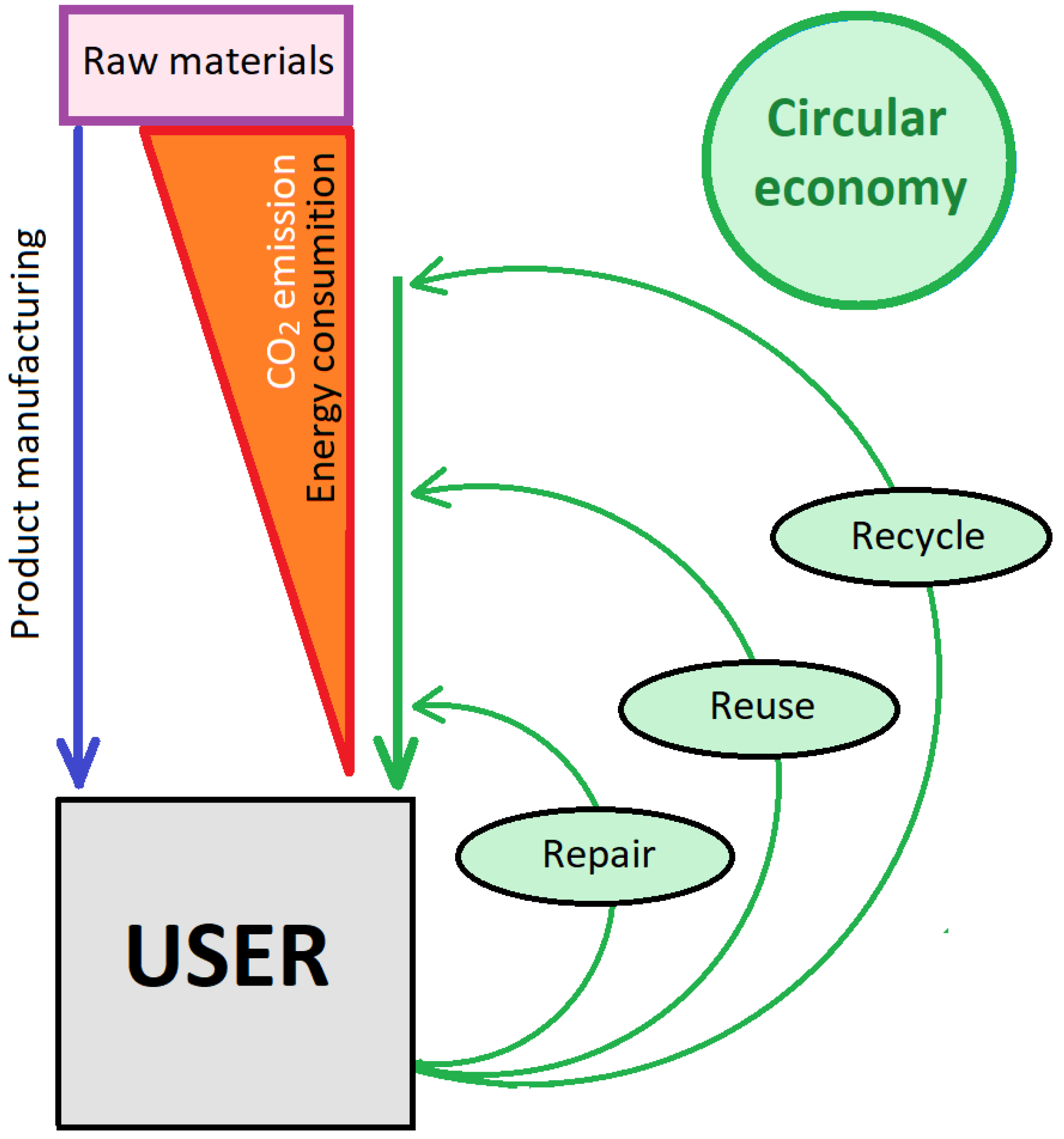
Figure 1. Scheme of the circular economy.
Sustainability 15 07808 g001
Figure 2. Example of a support structure for industrial conveyors.
Sustainability 15 07808 g002
Figure 3. (a) Bolted connection and (b) welded connection.
Sustainability 15 07808 g003
Figure 4. (a) Example of steel connection with blind bolts: (b) blind bolt before being tightened and (c) blind bolt after being tightened.
Sustainability 15 07808 g004
Figure 5. (a) Beam–end connection to perforated profile column in steel storage racks, (b) load-bearing structure made of steel racking, and (c) steel racking from perforated profiles.
Sustainability 15 07808 g005
Figure 6. (a) Example of a removable bracket, and (b) connection using bolts with removable brackets.
Sustainability 15 07808 g006
Figure 7. (a) Connection using disk lock, (b) scaffolding structure, and (c) connection by quick round tube couplers.
Sustainability 15 07808 g007
Figure 8. Different solutions for connecting tubular profiles with rectangular or square section columns through clamp-based systems: (a) transverse connection between beams, (b) beam-to-column connection, (c) removable base system for square or rectangular section columns, and (d) lateral connection of beams at any angle.
Sustainability 15 07808 g008
Figure 9. Example of a structure built with I-type profiles and clamp-based connections.
Sustainability 15 07808 g009
Figure 10. (a) Sketch of the flat-fitting clamps, and (b) sketch of the pivoting clamps.
Sustainability 15 07808 g010
Figure 11. Sketch of the lever mechanism in a clamp-based connection.
Sustainability 15 07808 g011
Figure 12. (a) Lateral connection at 90° of a transversal beam to the flanges of a column, (b) beam-to-column connection, (c) removable base system for I-type section columns, and (d) transversal connection of beams.
Sustainability 15 07808 g012
Figure 13. Failure modes of a clamped connection based on the T-stub methodology. (a) T-stub general scheme. (b) Failure mode 1. (c) Failure mode 2. (d) Failure mode 3.
Sustainability 15 07808 g013
Figure 14. Scheme of the two working modes of the clamp-based connection according to the analytical model based on the Eurocode T-stub model. (a) Mode A and (b) Mode B.
Sustainability 15 07808 g014
Table 1. Summary table of the different types of connections.
TypeRemovableReconfigurableApplicationNumber of References at Scopus (a)Research Level Based on Scopus ReferencesSustainable (b)
WeldedNoNoAll profiles type10,695very highvery low
BoltedYesdifficultAll profiles type2139highlow
Blind bolts YesdifficultSquare/rectangular tubes151mediumlow
Storage racksYesmediumContinuously perforated columns and beams equipped with quick hooks made using tabs171mediummedium
Scaffolding (disk locks)YesmediumRound tubes84mediummedium
Scaffolding (quick round tube couplers)YeseasyRound tubes14lowhigh
Bolted with removable bracketsYesmediumI-type profiles18lowhigh
I-type profiles by a collar connectionYeseasyI-type profiles and square/rectangular tubes9lowhigh
Clamp-based connections for I-type profilesYeseasyI-type profiles12lowvery high
Clamp-based connections for square or rectangular profilesYeseasySquare/rectangular tubes2very lowvery high
(a) All searches were performed in SCOPUS for: steel AND structures AND connection OR joint; (b) In this work, “sustainable steel structures” are defined as structures that are fully reconfigurable and reusable as many times as necessary.
Disclaimer/Publisher’s Note: The statements, opinions and data contained in all publications are solely those of the individual author(s) and contributor(s) and not of MDPI and/or the editor(s). MDPI and/or the editor(s) disclaim responsibility for any injury to people or property resulting from any ideas, methods, instructions or products referred to in the content.