Article

Numerical Parametric Study and Design of Pultruded GFRP Composite Channel Columns

1
Department of Civil Engineering, Government College of Engineering, Salem 636011, Tamil Nadu, India
2
Department of Civil Engineering, Sona College of Technology, Salem 636005, Tamil Nadu, India
3
Department of Mechanical Engineering, National Engineering College, Kovilpatti 628503, Tamil Nadu, India
4
Department of Structural and Geotechnical Engineering, Vellore Institute of Technology, Vellore 632014, Tamil Nadu, India
*
Authors to whom correspondence should be addressed.
Sustainability 2023, 15(1), 837; https://doi.org/10.3390/su15010837
Submission received: 11 November 2022 / Revised: 11 December 2022 / Accepted: 24 December 2022 / Published: 3 January 2023

Abstract

:
This article reports the finite element (FE) investigation of the axial capacities of pultruded fiber-reinforced polymer (PFRP) composite channel columns. The nonlinear finite element model (FEM) was developed by using the ABAQUS package for glass fiber-reinforced polymer (GFRP) composite channel columns, which included geometric and initial geometric imperfections. The developed FEMs were verified against an experimental result available in the literature for GFRP channel columns. The validated FEMs were used to carry out the parametric study comprising 61 FE models to investigate the effect of different geometries, plate slenderness and the length of members on the axial capacities of GFRP pultruded channel columns. The results obtained from the parametric study were used to examine the accuracy of the current Italian guidelines, American pre-standard and the Direct Strength Method (DSM) proposed in the literature for GFRP channel profiles. Based on the obtained results, the suitability of the current design guidelines is assessed and, also, a new set of design equations is proposed to estimate the axial capacity of the pultruded GFRP channel columns. The new proposed set of reliable design equations witnessed a less scattered and a high degree of accuracy in determining the axial load capacity of the pultruded GFRP composite channel columns.

1. Introduction

Fiber-reinforced polymers (FRP) are ideal to be used as structural load-carrying components due to their characteristics, such as being light weight, having great corrosion resistance, and a high strength-to-weight ratio [1]. As structural elements, steel and steel–concrete composites were utilised until the last decade. Then, FRP composites were utilised to repair, retrofit, and strengthen structural elements made of steel, concrete, and steel–concrete composite [2,3,4,5,6]. Later, due to the excellent mechanical properties, FRP composite members alone started to be used as structural load-bearing elements in the aircraft and automotive industries. Recently, the usage of FRP composite section profiles became more popular in civil engineering applications in the construction industry [7]. FRP manufacturers offer a variety of shapes, sizes, and materials. In the industry, open sections such as I, channel, and angle profiles are very popular.
The provisions for the design of pultruded structural members in the Bedford Reinforced Plastics Inc. [8], Creative Pultrusion’s Inc. [9], European standard EN 13076 [10], and EUROCOMP Design Code Handbook [11] are based on the Euler elastic theory. Due to their thin wall thickness and low stiffness-to-strength ratio, pultruded FRP columns are prone to buckling. Hence, the most common mode of failure for GFRP columns is buckling. Therefore, the primary goal of this research is to establish a simplified design method for the safe and effective design of GFRP channel columns.
After refining an empirical formula for designing wood members, Barbero and Tomblin [12] created a design equation for FRP columns that includes the interaction between global and local buckling. Zureick and Scott [13] provided test results on FRP I and box sections, as well as design recommendations. Based on analytical, numerical, and experimental research, Hashem and Yuan [14] and Barbero [15,16] showed that the Euler theory can be used to obtain a reasonably accurate estimate of the global buckling load. Kollar [17] developed closed-form equations to estimate the local buckling strength of FRP composite profiles. Qiao and Zou [18] used explicit formulas to estimate the wide flange column buckling strength. This was achieved by taking the flexibility of the web–flange connection into account.
Puente et al. [19] investigated the pultruded hollow circular columns, created a set of empirical models to determine the hollow circular column’s strength, and validated the same with experimental results. Turvey and Zhang [20] created the FE model to estimate pultruded wide flange column buckling and post-buckling failure stresses. Bai and Keller [21] introduced a new design formulation to determine compression members’ ultimate load with second-order deformation and shear failure. For PFRP columns subjected to both global and local buckling, Vanevenhoven et al. [22] developed a unified design statement. Cardoso et al. [23] derived compressive strength equations for GFRP square tubes. Minghini et al. [24], Russo [25,26], and Boscato et al. [27] studied PFRP built-up columns’ compression strength and behaviour.
Higgoda et al. [28] investigated GFRP hollow circular columns by conducting both an experimental and numerical study. They observed predominant failure modes such as longitudinal splitting and localised delamination buckling during the test. Based on the curve fitting technique, Kasiviswanathan and Upadhyay [29] proposed strength equations to predict the axial capacities of hollow GFRP columns. Zhan and Wu [30,31] developed an innovative closed-form design equation based on the Ayrton–Perry formula to estimate the load capacity for pultruded doubly symmetric cross-sections subjected to global buckling. Kulkarni [32] studied the buckling of I-section pultruded profiles under uniform axial compression.
From the past studies, it is observed that the buckling strength of the pultruded GFRP compression members is substantially influenced by geometry nonlinearity, material damage modelling, and geometry defects. Therefore, this study aims to investigate the critical buckling resistance of pultruded channel columns by including the key parameters such as geometric nonlinearity, damage modelling, and imperfections. The verified FEMs were used to conduct the parametric study on GFRP pultruded channel columns. The numerical results were used to examine the applicability of the strength equations proposed by other researchers and design guidelines. Based on the comparison of the results, a new set of simplified design formulation based on nonlinear regression analysis using the least squares method is proposed to estimate the critical buckling strength of axially loaded GFRP channel column members. Finally, the closeness of the proposed new design equations of the channel GFRP column to the proposed design equation of other researchers is discussed. A justification for the proposed new set of design equations is also made in this article by comparing the merits and demerits of the existing strength equations.

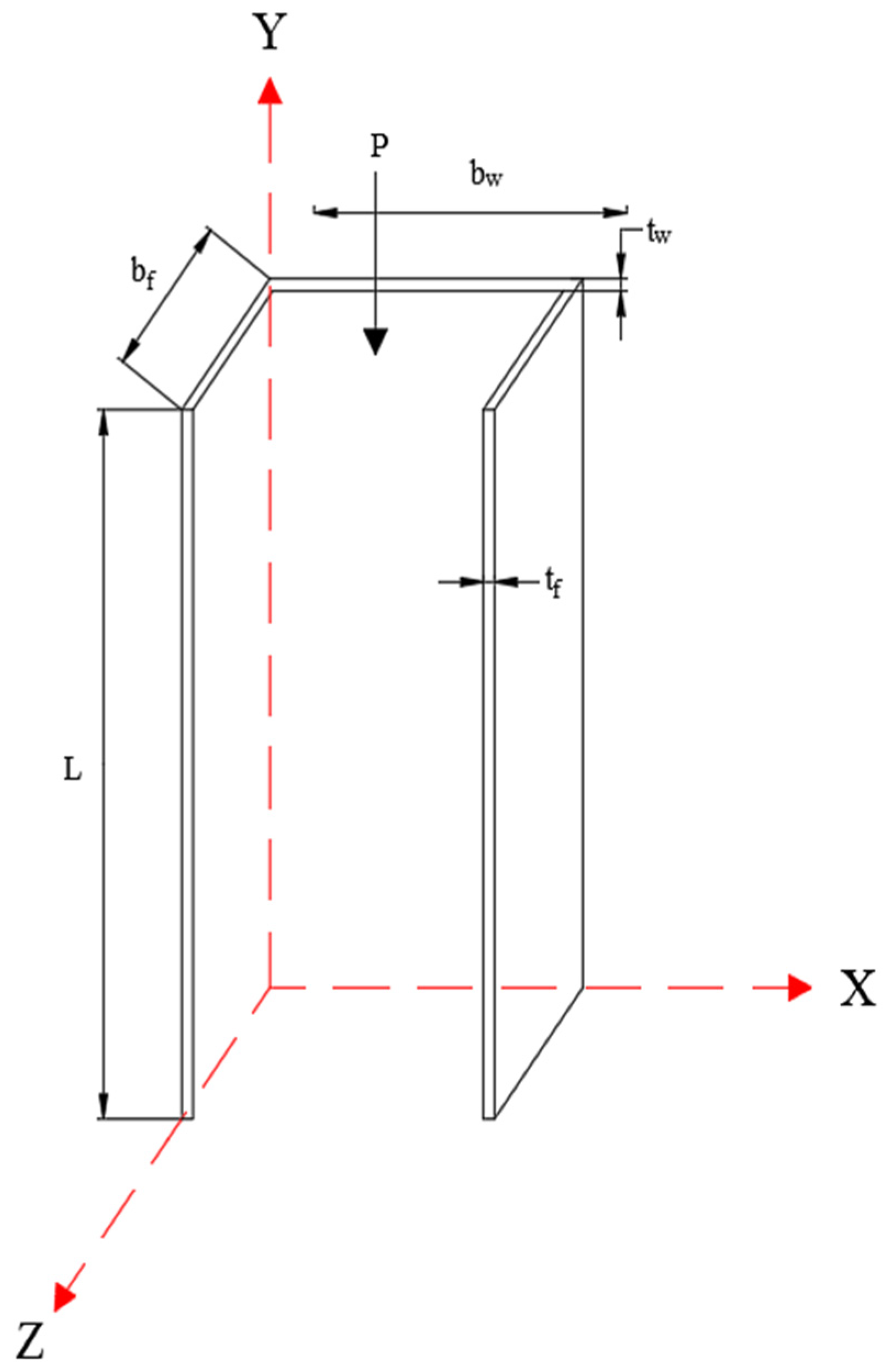
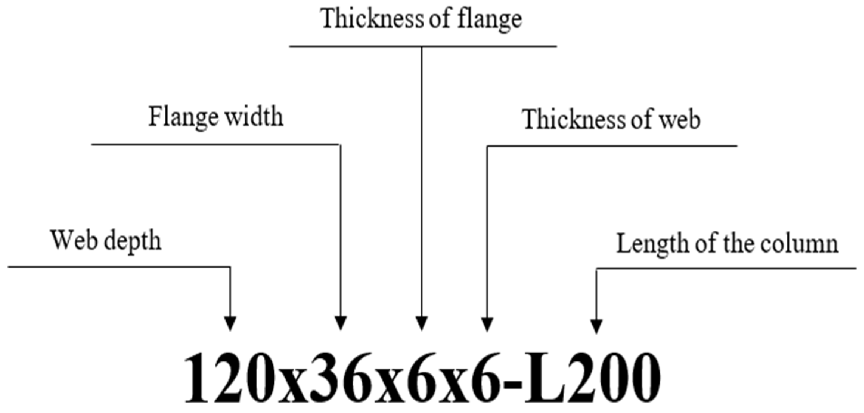
2. Geometry of Column

The parameter that corresponds to the geometry of the column and a simplified column is shown in Figure 1. Based on the dimensions of each column considered in this study, they are categorised with the general code format ‘bw x bf x tf & tw x L’ to distinguish each sample from other categories. Here, the letters ‘bw’, ‘bf’ ‘tf & tw’, and ‘L’ represent the web depth, flange width, thickness of flange, thickness of web, and overall length of the section, respectively. A uniform axial compressive load ‘P’ was applied along the axial of the column at the top end of the column length ‘L’. For example, Figure 2 shows the labelling of a GFRP column with a 120 mm depth, 36 mm flange width, 6/6 mm thickness of flange and web, and 500 mm overall length. In order to cover a wide range of practical geometries, sections were taken from the Fiberline design manual. Table 1 shows the dimensions and column configurations considered in this study. The numerical analysis was performed for the GFRP column with channel section considered in this study using ABAQUS® [33] software. The procedure followed for the same is explained in the following section.

3. Numerical Analysis

3.1. General

ABAQUS [33] was used to create numerical models using finite element analysis. Nonlinear analyses employing the RIKS solver in ABAQUS [33] were used to account for the impact of geometric nonlinearity and geometric defects. Finite element models were validated against published results to confirm their accuracy. Extensive parametric analysis was performed to develop a database for the development of an updated design strength curve, which was then used to provide predictions about the critical buckling strength of the GFRP channel columns.

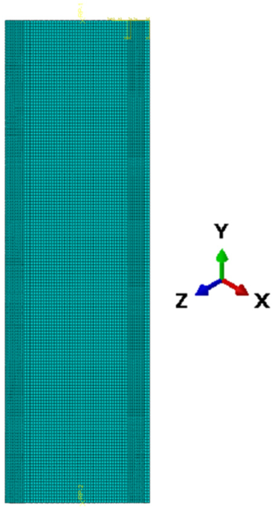
3.2. Element Type and Mesh

The GFRP channel columns were made with the broadly used four-node shell element S4R. Each node has six degrees of freedom (three rotational and three translational). Previous finite element studies have successfully used this shell element. Figure 3 shows the discretised channel FE model. A 5 × 5 mm element with a 1 aspect ratio was chosen based on mesh sensitivity.

3.3. Material Properties

The parts of the channel column were modelled in ABAQUS based on the properties of the GFRP material. Material law and the mechanical characteristics used in this investigation were taken from Nunes et al. [34]. Table 2 and Table 3 show the mechanical characteristics of the GFRP and channel beam dimensions. FE modelling did not incorporate composite failure criteria because specimen lengths were chosen to fail by buckling. According to Zhan and Wu [31], the FE model does not take into consideration residual stresses.

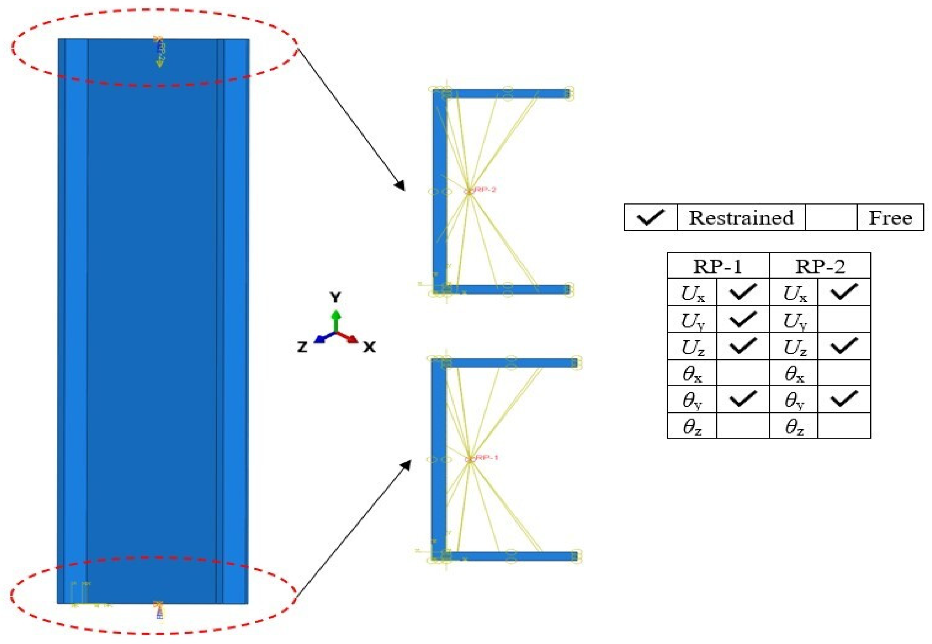
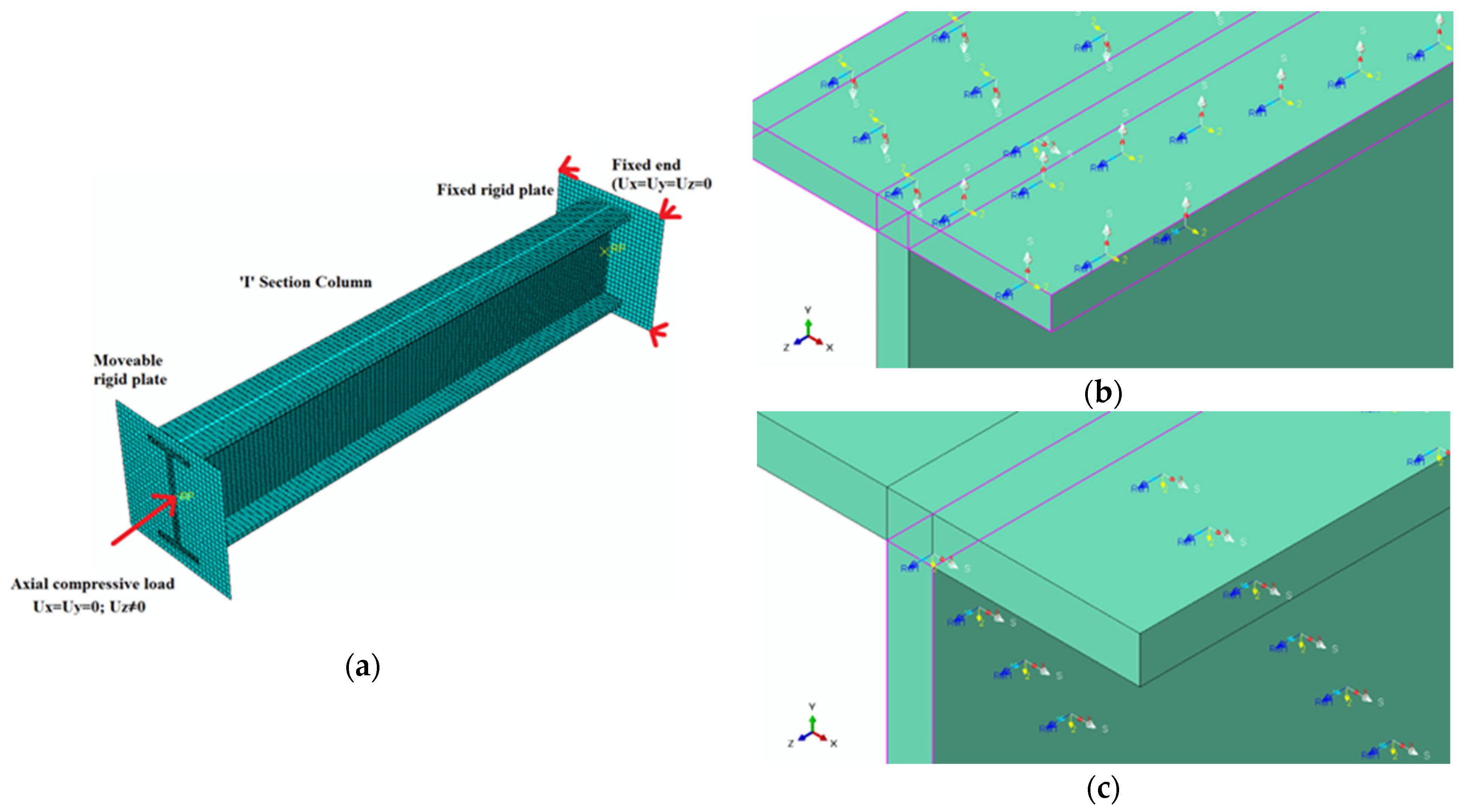
3.4. Loading and Boundary Conditions

The rigid region was constructed by creating nodes in the cross-centroid sections at the top and bottom ends and then connecting them to the nodes at the cross-edge. Every section’s node is dependent on the edges of the sections. These dependent nodes were connected to the independent node that is made at the centre of each section’s cross-section. As can be seen in Figure 4, the central master node was used to apply loading and boundary conditions.
The three axes selected were: X and Z axes were normal to the walls, while the Y axis ran the length of the member. To model the pinned end of a pultruded channel column, the loaded end could not move in either the X or Z directions. In contrast, as shown in Figure 4, the end that was not loaded could not move in three directions: X, Y, and Z.

3.5. Geometrical Imperfections

Geometric imperfections in manufacturing, shipping, and fabrication have the greatest impact on load carrying capability. Therefore, geometric imperfections were taken into account in the nonlinear analyses. According to the lengths of the local and global geometrical defects, they were incorporated into the model. For shorter and longer specimens, local and global imperfections were chosen. For specimens of medium length, both local and global defects were used. Column lengths were determined in order to cover a wide range of slenderness values intended to result in short (λ ≤ 0.7), intermediate (0.7 < λ < 1.3), and long columns (λ ≥ 1.3). The numerical models included 1/10 of the column thickness for local imperfection (Czapski and Kubiak [35]). According to the Fiberline design manual [36], global imperfections were added to the model by scaling the lowest buckling mode to a value of L/500. This is similar to how local imperfections were added. After imposing the initial geometrical imperfection, geometric nonlinearity was incorporated by using the large displacement analysis option.

3.6. Elastic and Nonlinear Analysis

To predict the axial strength of hollow columns, two stages of analyses were performed. The critical buckling load with corresponding buckling mode shapes were determined by performing the eigen buckling analysis. This was followed by the nonlinear static analysis, which was performed by using Newton–Raphson’s method to determine the critical buckling strength of the GFRP members. The imperfections (geometry imperfection) were introduced in the geometry by adding the critical buckling mode shapes to the perfect geometry of the hollow column by using the imperfection option in the nonlinear load–displacement analysis.
The determination of the buckling factor of the nonlinear analysis is quite a tedious procedure in the case of composite structures. The literature recommends various methods to determine the buckling factor. After examining all the methods, the Southwell plot was found to be more suitable for all the cases and it was hence adopted for the determination of the buckling factor for nonlinear analysis by following Cardoso et al. [37] and Correia et al. [38].

4. Parametric Study

The critical buckling strength and behavior of pultruded GFRP channel columns were examined using parametric analysis. To accommodate a wide range of slenderness, the section length was increased from 400 mm to 1750 mm. Based on the Fiberline composite design manual [36], eleven commercially available channel sections were taken into consideration in this investigation. To investigate the behavior of pultruded GFRP channel columns, 59 finite element models were examined. The parametric study’s findings are displayed as deformed forms and buckling strength. The current study’s modified strength equations, based on nonlinear regression analysis utilising the least squares approach, are compared to the results of the finite element analysis. The FE analysis findings are also compared to the predictions of the design guidelines.

5. Results and Discussion

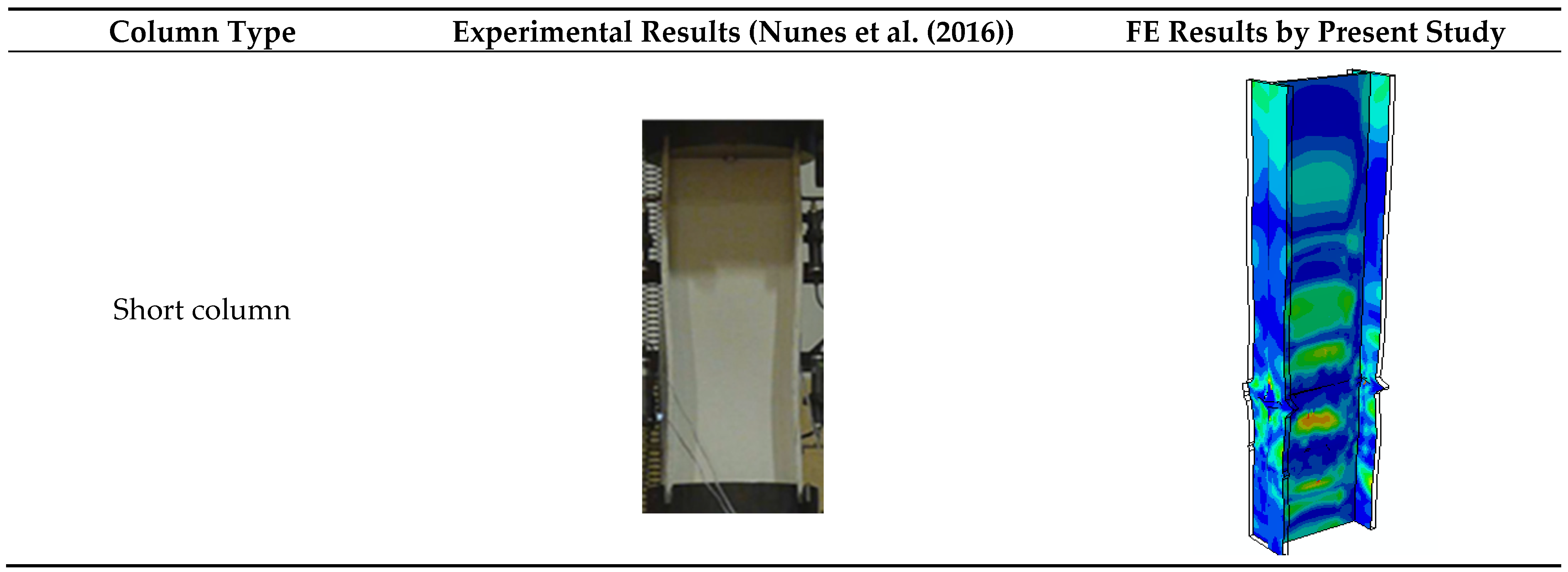
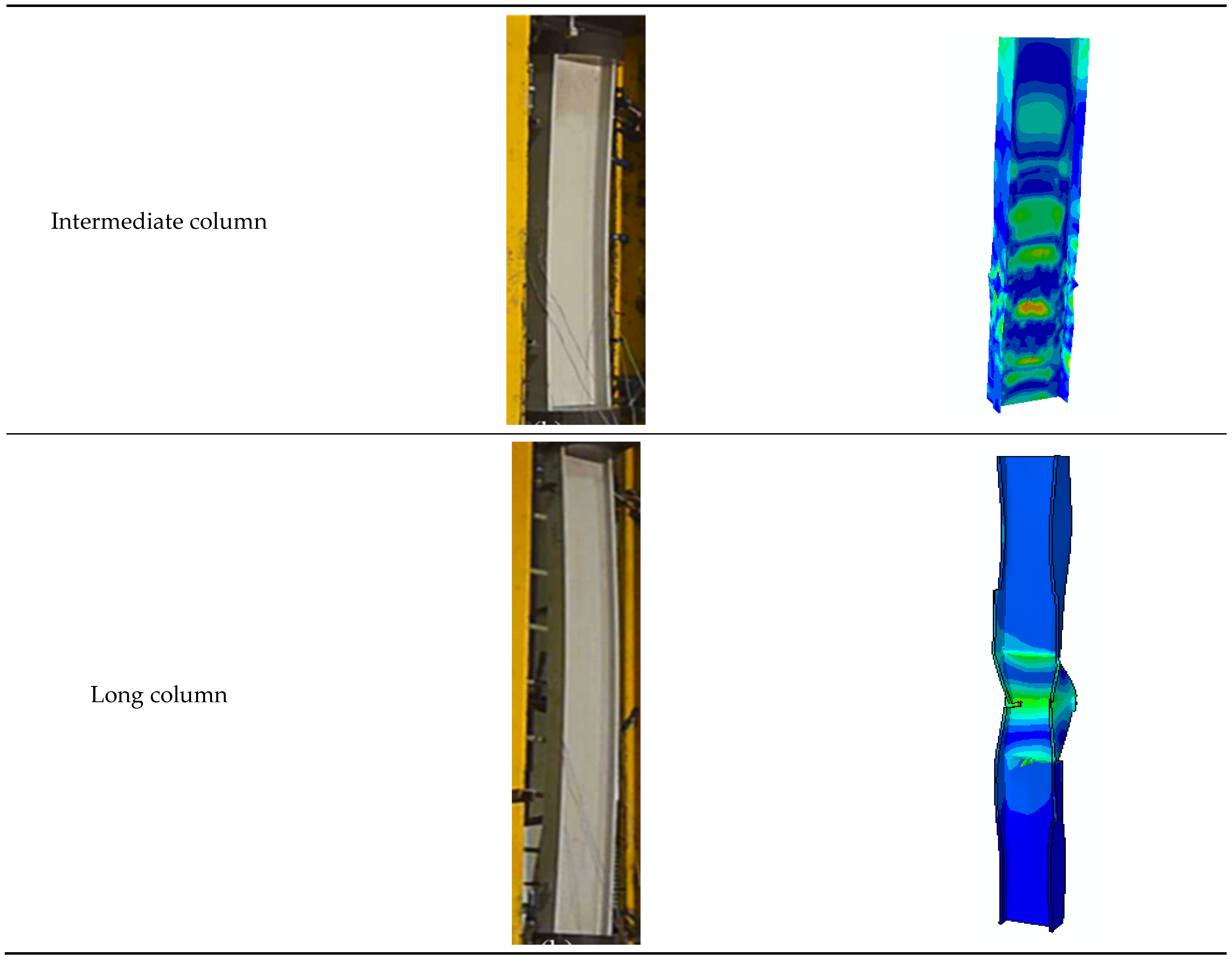
5.1. Validation of FEMs

The experimental results of Nunes et al. [34] for pultruded GFRP I columns were replicated in order to validate the FE model. Table 4 shows the dimensions of the validated columns. The column was modelled and meshed with an eight-node quadrilateral in-plane general-purpose continuum shell element. One of the FE models of the column is shown in Figure 5a. The unidirectional GFRP material properties were obtained from Nunes et al. [34], shown in Table 2 and 3, and the same were used to model the GFRP column components. A Cartesian coordinated local axis system was assigned the I section column in such a way that the principal axis was aligned with the longitudinal axis of the fiber, and it was oriented along the length of the column. The secondary axis of the coordinate system was aligned in such a way that it was perpendicular to the first direction, i.e., longitudinal direction of the fiber orientation, as shown in Figure 5b,c.
Further, two square-shaped numbers of rigid plates were created, and the column was sandwiched in between the two rigid plates. These rigid plates were meshed with four-node 3D bilinear rigid quadrilateral elements (R3D4) of a mesh size of 9 mm × 9 mm to obtain element grids of a uniform size. One of the rigid plates was attached with one end of the column and it is fully fixed. Another rigid plate was allowed to move only along the ‘Z’ direction. The nodes of the moveable rigid plate were tied up with one end of the column, and the nodes of the fixed rigid plate were also tied to the other end of the column, as shown in Figure 5a. The axial compressive load was applied from the moveable rigid plate over the column along the ‘Z’ direction, and the elastic load limit and buckling characteristics of the column were studied using Eigen buckling analysis, Static, and the RIKS methods employed in ABAQUS software.
Table 4 compares the experimental buckling load to the critical buckling load of the nonlinear analysis. The mean critical buckling strength of the experimental to finite element analysis of the pultruded GFRP I columns is 0.962, with an STD. DEV. of 0.016. Table 4 shows that, for pultruded I columns, the experimental findings and the results predicted by FEA were nearly identical. The failure mode forms of short, middle, and long columns that were published by Nunes et al. [34] for pultruded GFRP I columns are compared with the finite element analysis in Figure 6.

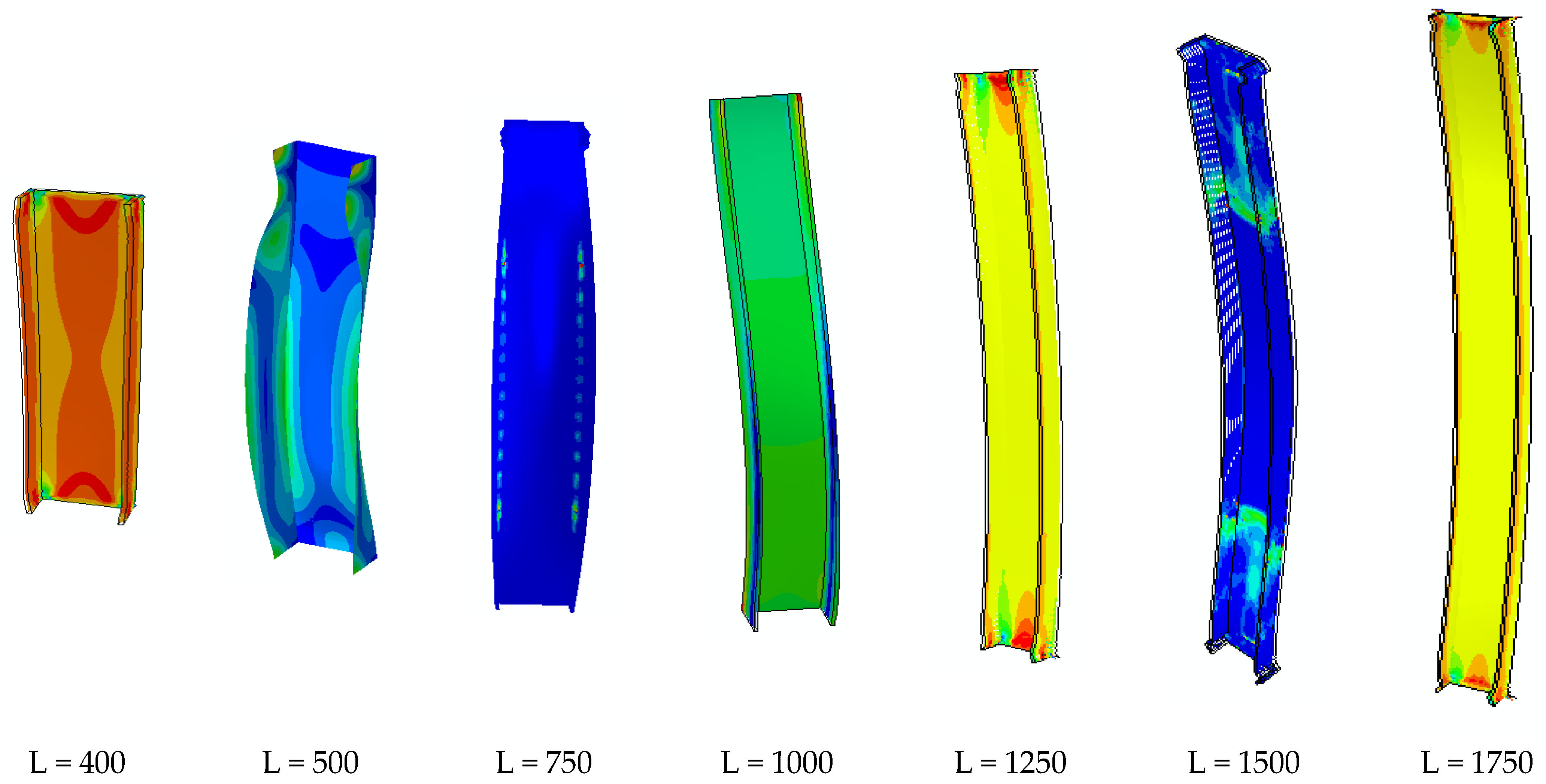
5.2. Behaviour and Deformed Shapes

In a parametric analysis, both local and global buckling failures were generally observed as failure modes. Typically, local buckling occurs when the column slenderness (λ) is less than 1.0. (See Figure 6). The minor axis typically induced localised buckling by opening or shutting in a single half-sine wave at the critical stress in the thin plate element of the channel section. The crushing failure of the PFRP columns was precluded by selecting the appropriate geometry (length and thickness), as demonstrated in Figure 6. When λ was more than 1.0, global buckling occurred (See Figure 6). A buckling collapse developed along the weaker axis. The analysis revealed no local–global interaction buckling failure. Figure 7 shows the local and global buckling modes from the 120x50x6x6 finite element analysis.

5.3. Reliability Analysis

In this section, reliability analysis is performed to analyse the applicability of the existing and proposed design recommendations for the axial capacity of pultruded GFRP channel columns. The relative safety of a given design is determined via reliability analysis using the reliability index (β). If a design’s reliability index value is greater than that of another design, it is assumed that the design’s relative safety or reliability is greater. The methods outlined in the Commentary part of ASCE 802 [39] were utilised in this study to conduct a reliability analysis. Due to the weak ductility of pultruded FRP members, the desired reliability index values for member limit states must be higher than for cold-formed steel (NAS) [40] and stainless steel (ASCE 802 [39]) members. In this instance, the pre-standard for LRFD of pultruded FRP structures [41] establishes a target reliability range of 3.50–4.00 for material strength limit states. In the present study, the lower bound value of 3.5 is chosen as the target reliability index for determining the applicability of the existing and new design principles. As specified in the specification, the resistance factor for compression members is presumed to be 0.85. The 1.2DL + 1.6LL load combination is considered in compliance with the ASCE Standard [39], where LL represents live load and DL represents dead load. According to the NAS specification, the ratio of dead load to live load is 0.2. According to Table K2.1.1–1 of the NAS Specification [40], the statistical data utilised for the reliability analysis were determined: Mm = 1.10 and VM = 0.10 are the mean value and coefficient for material characteristics, Fm = 1.00 and VF = 0.05 are the mean value and coefficient for the fabrication factors, respectively, and Pm is the mean value and VP is the coefficient of variation of the tested-to-predicted load ratios. CP is the correction factor used in the reliability study to account for the influence of test number. In Table 5, the means (Pm) and coefficients of variation (Vp) of the ratio of FE axial strength to predicted strength utilised in the reliability analysis are presented. Table 5 shows the present and recommended values for the design formulas. If the value is 3.5 or higher, the design formulas are considered to be accurate.

6. Strength Equations

To evaluate the design strength equations for pultruded GFRP columns discovered in the literature, such as the DSM technique [42], ASCE pre-standard [41], Cardoso et al.’s [37] design Procedure, and the Italian Code Approach [43], the results of the FE analysis were compared. A total of 59 FE-generated axial compression resistances of pultruded GFRP channel columns were compared to previously established design strength equations and the design equations developed in this study.

6.1. DSM Method [42]

The ultimate load estimate as
P c , R = χ l P c , R ( g )
where Pc,R(g) is the global strength given by Equation (2) and χl is a non-dimensional parameter that defines the strength curves in local buckling analysis according to Equation (1).
P c , R ( g ) = { ( 0.915 / λ 0 2 ) A g F L , c   i f   λ c > 1.4 ( 0.915 λ 0 2 ) A g F L , c   i f   λ c   1.4
χ l , p i n = { [ 1 + 0.25 ( P c r F T / P c , R ( g ) ) ] ( P c r F T / P c , R ( g ) ) i f   λ l > 1.150 1   i f   λ l   1.150
λ 0 = A g F L , c P c r F
λ 1 = P c , R ( g ) P c r l
where the slenderness parameters are given by λ0 = (AgFL,c/PcrF)0.5 and λ1 = (Pc,R(g)/Pcrl)0.5, and Pcrl is the local critical buckling load.

6.2. ASCE Pre-Standard [41]

Ultimate load can be calculated by Equation (6).
P u = m i n { P c r ;   P c o m p }
where Pcr and Pcomp are the critical load and compression force, which can be obtained by using Equations (7) and (8).
P c o m p = F L c o m p A g
P c r = F c r A g = m i n { F c r x ; F c r y ; F c r f ; F c r w } A g
where Fcrx and Fcry represent the elastic flexural buckling stresses in the x and y axes, while Fcrf and Fcrw represent the local buckling stresses at the flange and web, respectively. The lowest value of Fcrx, Fcry, Fcrf, and Fcrw are taken as the factored critical stress (Fcr).
F c r x = π 2 E L ( k x L r x ) 2
F c r y = π 2 E L ( k y L r y ) 2
F c r x = G L T ( b f 2 t f ) 2
F c r w = ( π 2 6 ) ( E L , w   E T , w + ϑ L T   E T , w + 2 G L T ) ( d w t w ) 2

6.3. Cardoso et al.’s [37] Design Procedure

Cardoso et al. [37] proposed a strength equation for calculating the axial compression capacity of GFRP I columns. This is shown below: Using Equation (13), we can calculate the GFRP pultruded columns’ nominal compressive strength (Pn).
P n = χ A ( Min .   of   ( F c , F c r l ) )
where the reduction factor (χ) is the smallest of the reduction factors for plate strength and column strength. The plate strength reduction factor (χp) can be calculated as follows:
χ p = ( 1 + α P L + λ p 2 ( 1 + α p l + λ p 2 ) 2 4 λ p 2 ) / 2 λ p 2 ( 1 + λ p 2 ( 1 + λ p 2 ) 2 4 λ p 2 ) / 2 λ p 2
where λp is the relative plate slenderness, and α is the plate imperfection parameter (=0.015).
λ p = F c F c r l
where Fc is the material crushing strength and Fcrl is the critical local buckling stress.
F c = G 12 ( 1 + χ c r / a ) b
where a = 0.21, b = −0.69, and χcr = 5.148.
To determine the local critical buckling stress Fcrl, we can utilise the formula given in Equation (17). For rectangular tube sections constructed of orthotropic material, the local buckling coefficient (kcr) can be calculated using Equation (18), as suggested by Cardoso et al. [37].
F c r l = k c r π 2 E L 12 ( 1 υ L T υ T L ) ( t b w ) 2
where EL is the longitudinal plate modulus of elasticity; υTL and υLT are the minor and major poisons ratios, respectively; t its thickness; and bw is the web width.
k c r = 2 1 + 4 π 2 η 3 / 3 E T E L + 2 υ L T E T E L + 4 ( 1 + 4 η ) ( 1 υ L T υ T L ) G L T E L 1 + 4 π 2 η 3 / 3
where η = bf/bw, bw is theidth of web, and bf is the flange width.
The column strength reduction factor (χc) is obtained as follows:
χ c = F u F p = 1 + α + λ c 2 ρ p ( 1 + α + λ c 2 ρ p ) 2 4 λ c 2 ρ p 2 λ c 2
For a perfect column (χ0), α = 0 and ρ p = 1 .
The column strength reduction factor (ρp) is the ratio of actual-to-ideal column normalised column strengths. α is the column imperfection parameter (=0.34). Using Equation (20), we can determine the relative slimness of the columns.
R e l a t i v e   c o l u m n   s l e n d e r e n s s   ( λ c ) = F p F c r g
The perfect plate strength (Fp) is a minimum of (Fc&Fcrl) according to Barbero and Tomblin [12] and Zureick and Scott [13], where, Fc is the material crushing strength, Fcrl is the critical local buckling stress, and Fcrg is the critical global buckling stress. Cardoso et al. [37] recommend Timoshenko and Gere’s [44] equation with shear effect to compute the critical global buckling stress, as in Equation (21).
F c r g = 1 + 4 η s F e G L T 1 2 η s G L T
where F e = π 2 E L / ( K e L / r ) 2 is the Euler critical buckling stress; GLT is the in-plane shear modulus; ηs is the shear form factor; r is the radius of gyration; KeL is the effective length of the column; and EL is the longitudinal modulus of elasticity.

6.4. Italian Code Approach [43]

In the case of elements subjected to axial compressive load, the design resistance Nc,Rd can be obtained from the relation.
N c , R d = m i n { N c , R d 1 , N c , R d 2 }
where Nc,Rd1 is the pultruded element’s compressive force value and Nc,Rd2 is the design compression value that causes the element’s instability.
The following expression can be used to determine the value of Nc,Rd1.
N c , R d 1 = A f c
The value Nc,Rd2 can be obtained by using Equation (24).
N c , R d 2 = χ N l , R d = χ A f l γ f
Large beam experiments or numerical/analytical modelling can both be used to determine the value of Nl,Rd. Alternately, the following relation can be used to obtain it.
N l , R d = A f l
The value of local critical stress, fl can be calculated as
f l = m i n { f l f , f l w }
where f l w and f l f are the uniformly compressed flange’s and web’s critical stresses. These can be determined through the following conservative relation.
f l f = 4 G L T ( t f b f ) 2
f l w = k c π 2 E L t w 2 12 ( 1 υ L T υ T L ) d w 2
The coefficient kc is obtained from the relation.
k c = 2 E T / E L + 4 G L T E L ( 1 υ L T 2 E T E L ) + 2 υ L T E T E L
The coefficient χ in Equation (30) is a reductive factor which considers the interaction between the global and local instability of the element. This can be obtained through the expression.
χ = 1 c λ 2 ( 2 + c λ 2 )
where c is the numeric coefficient that can be presumed to equal 0.65 in the absence of more accurate tests. φ is the auxiliary coefficient that can be calculated by using the below expression.
φ = 1 + λ 2 2
The column slenderness λ is equal to
λ = N l , R d N E
NE is the flexural (Euler) buckling load, which is calculated by Equation (33).
N E = 1 γ f π 2 E I m i n L 2

7. Assessment of Current Strength Predictions in the Literature

The design methods specified in the Direct Strength Method (DSM) [42], American pre-standard [41], Cardoso et al.’s [37] design approach, and the Italian guidelines [43] were assessed by comparing the numerical strengths (namely the critical loads) with the predicted values. The comparison of Pcr with the Direct Strength Method (Pcr-DSM) [42], American pre-standard (Pcr-ASCE) [41], Cardoso et al.’s [37] design approach (Pcr-Car), and the Italian guidelines’ (Pcr-Car) [43] predictions are shown in Figure 8 and Figure 9. Table 5 provides a quantitative analysis of the strength comparison.
In general, the nominal strengths estimated by the DSM’s [42] design strength calculations are conservative. The average Pcr-FEA/Pcr,DSM is 1.18, with the corresponding COV being 0.128. In Figure 8, all data points are found above the dotted line, indicating that the predictions are on the conservative side. Compared to the numerical strengths, the predicted values are almost 18% higher. Moreover, the DSM’s [42] design rule is reliable, with the reliability indexes (β) more than 3.5. The DSM’s [42] design equations’ predictions are reasonably accurate for GFRP composite channel columns under axial compression.
Figure 8 shows that the ASCE pre standard’s predictions of axial strengths are conservative for the low slenderness range of stock sections but are not conservative for the remaining slenderness range. The mean value of Pcr-FEA/Pcr-ASCE is 1.00 and the corresponding COV is 0.100. For small slenderness, it provides highly conservative results, which is clearly visible from Figure 9. The reason for this is that ignoring rotational restraint at the web–flange junction, i.e., considering simply supported edges, results in a lower critical load than including flange rotational restraint. For medium and high slenderness, it provides unconservative results. It implies that the ASCE pre-standard is not good enough in predicting the axial strength of the GFRP composite channel columns. Furthermore, the computed reliability index of 3.41 fails to achieve the target value of 3.50, showing the inadequacy of the ASCE pre-standard in estimating the axial critical strength of the GFRP composite channel columns.
Cardoso et al.’s [37] strength equations for pultruded GFRP channel columns are conservative, as seen in Table 5. The mean ratio of FEA to predicted critical strength (Pcr-FEA/Pcr,Ca) is 1.36, with a standard deviation of 0.180. As shown in Figure 9, the strength estimates by Cardoso et al. [37] are considerably conservative for λ values less than 1.5 and moderately conservative for λ values greater than 1.5. Most of Cardoso et al.’s [37] test specimens failed in crushing in the range of low-to-medium relative slenderness, which leads to the inaccurate predictions.
The design equations based on the Italian recommendations [43] are generally too conservative with respect to the critical compressive strength (Pcr-Ita) (Table 5). The average of Pcr-FEA and Pcr-Ita. is 1.33, the standard deviation (STD. DEV.) is 0.147, and the reliability index (β) value is significantly greater than 3.5 due to the extremely conservative predictions. Figure 9 depicts the comparison of the FE parametric findings with the Italian guidelines’ [43] strength curve. It can be seen from Figure 9 that the Italian guidelines’ [43] strength estimates for relative slenderness (λ) between 0.4 and 2 are overly conservative. The reason is the interaction between global and local buckling modes is not considered. For low and high relative slenderness, the Italian guidelines’ [43] strength predictions are on the safer side and just below the FEA results. Even though the design equations of the Italian guidelines [43] provide conservative results, the strength predictions are scattered. The comparison of results shows the inadequacy of the strength predictions of the Italian guidelines’ [43] strength equations.

8. Assessment of Proposed Design Formulation

For pultruded GFRP channel columns, a full-span design strength curve was generated. From Table 5 and Figure 8, it is observed that the existing equations are less precise in estimating the strength of pultruded GFRP channel columns. A set of novel design equations has been proposed to forecast the axial strength of GFRP channel columns; these equations are based on the curve fitting technique. Using regression analysis, the best-fitting curve was generated based on the available numerical parametric research data (Similar to Refs. Anbarasu and Kasiviswanathan [45], Anbarasu and Dar [46], and Kasiviswanathan and Anbarasu [47]). Two-stage curves are proposed in Equation (34), which is based on nonlinear regression analysis with the least squares method. The non-dimensional slenderness value (λ) is a function of the reduction factor (χ), which accounts the imperfection sensitivity of PFRP channel columns.
χ = { 0.768 λ 2.384 f o r λ > 1.40 ( 0.889 λ 2.957 ) ( 0.331 λ 1.034 ) f o r 1.40 < λ }
Table 5 demonstrates that the proposed Equation (34) predicts reliable and safe results. The current study’s mean value of the numerical-to-recommended design equation for the axial strength ratio Pcr-FEA/Pcr-Prop is 1.05, with a standard variation of 0.065. The comparison of FE strengths with the suggested design equations is shown in Figure 8, and the findings show that the newly formulated design proposals can result in reliable and accurate results. As shown in Table 5, the reliability index (β) is greater than 3.5 when combined with the resistance factors (ϕ), indicating that the newly proposed design principles are reliable for the design of GFRP composite channel columns. Furthermore, in Figure 9, the axial capacity calculated using numerical methods (FEA) is compared to the design procedure provided in this study for various non-dimensional slenderness (λ). It is clear from this diagram that the proposed equation yields more conservatively accurate results.

9. Conclusions

This paper presents the numerical investigation on the axial behaviour with the associated post-buckling failure mode of GFRP composite channel columns using a finite element programme. This study incorporates material failure criteria, initial geometric imperfections, and large deformation effects. The reliability of the proposed FE analysis results was validated by comparing to the related test results published in the literature. Based on this study, the following conclusions were drawn.
  • The proposed FE modelling procedure replicates the experimental work to determine the critical buckling load and behavior of GFRP composite channel columns with high accuracy.
  • As expected, all of the short GFRP composite channel columns are found to fail under local buckling with significant post-buckling strength. Similarly, all of the slender GFRP composite channel columns fail overall axial buckling.
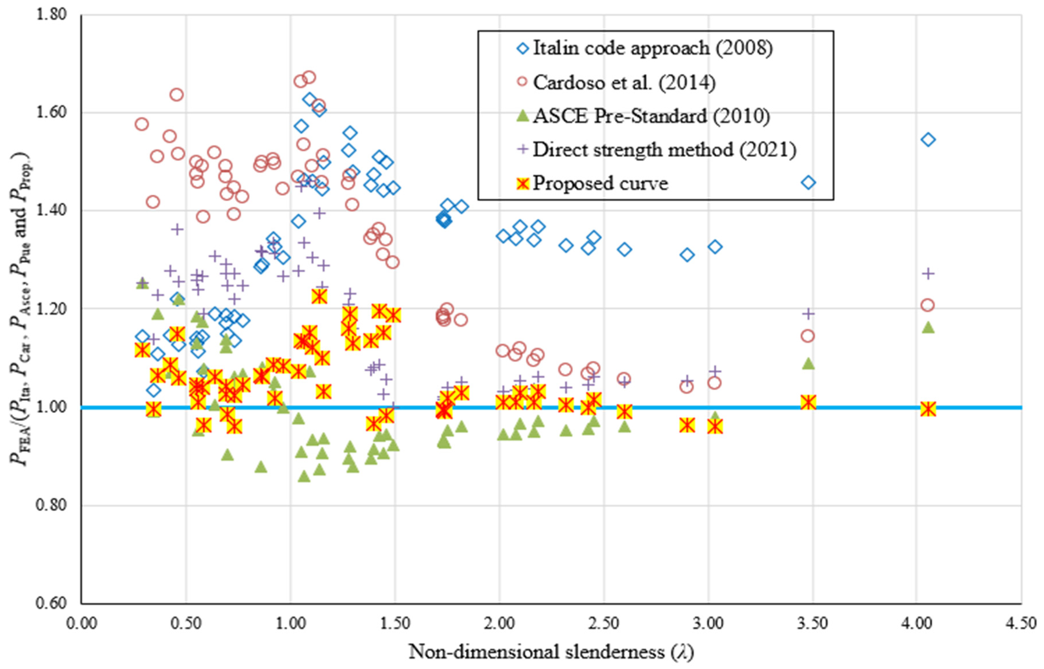
  • The axial compressive strength predicted by the DSM is conservative, with the mean and COV for predictions being 1.18 and 0.108, respectively. The conservatism is greater in the low slenderness range. Overall, the DSM predictions are reasonably accurate in estimating the compressive strength of the GFRP composite channel columns.
  • The ASCE pre-standard axial compressive strength predictions provide a better average over the other methods, but marginally failed to reach the target reliability index of 3.50.
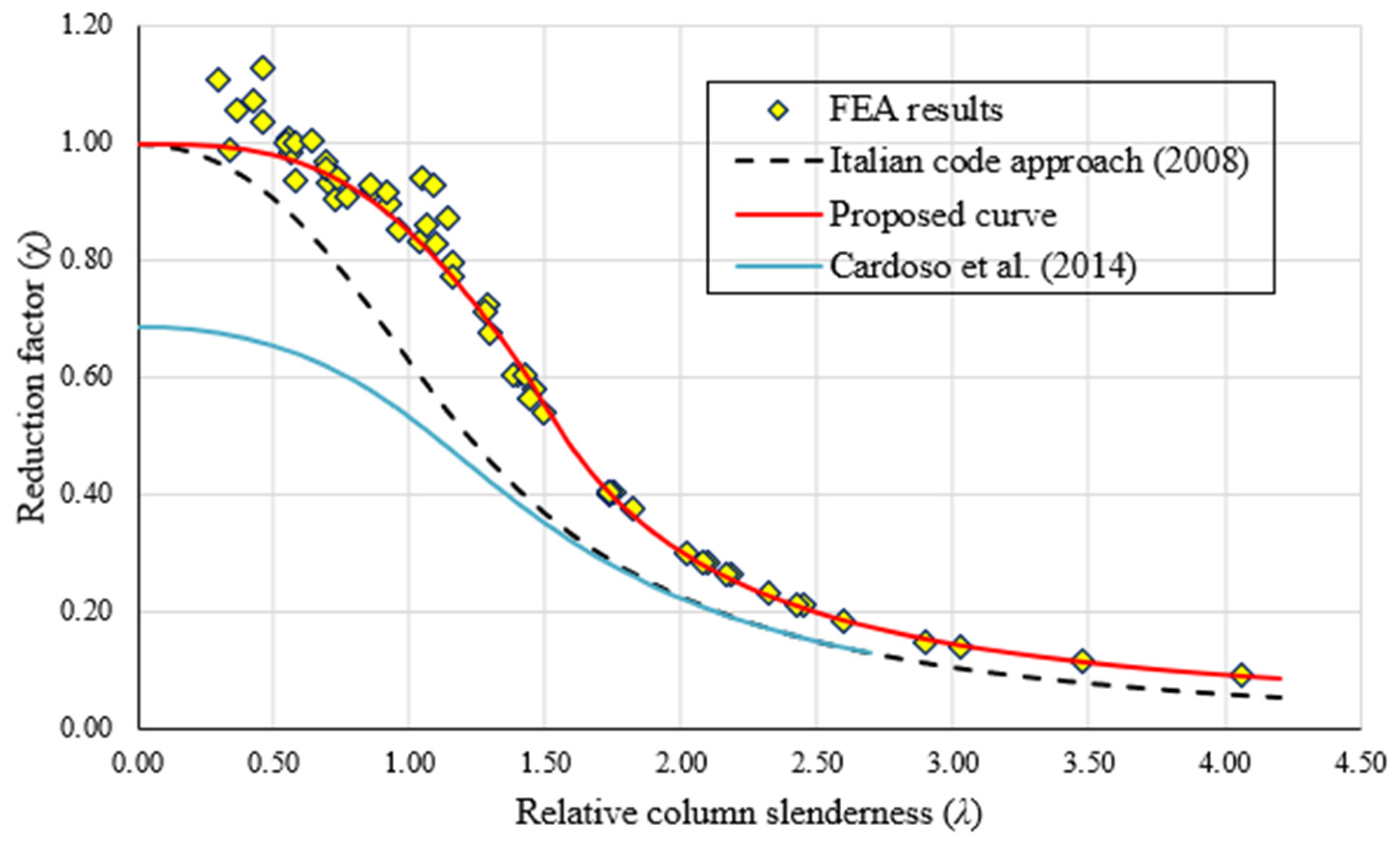
  • The design strength equation proposed by Cardoso et al. for pultruded GFRP columns and by the Italian guidelines exhibits significantly conservative predictions for the low and medium relative column slenderness. Overall, they conservatively predicted the strength, with a mean of 1.36 and 1.33 and with a reliability index much greater than target reliability index of 3.5. However, it appeared to be incapable of reasonably predicting the strength of the pultruded GFRP channel columns which are precluded from crushing failure and interactive local–global buckling.
  • A new design proposal was developed considering the geometric imperfections and the material failure criterion and performed better than existing design methods. The obtained predictions were in very good agreement by producing a mean of 1.05, with a COV. of 0.065. It is proved that the newly developed design equation is able to provide accurate and reliable predictions. Due to its relatively straightforward, simple, and familiar form, the proposed design equation is suited for the structural design applications of a wide range of FRP sections in the market.
Additional experimental investigations are required to confirm these numerically developed strength equations and the observed behaviour.

Author Contributions

Methodology, M.A. and M.K. (M Kasiviswanathan); Validation, M.K. (M Kathiresan); Investigation, M.K. (M Kasiviswanathan); Writing—original draft, M.A. and M.K. (M Kasiviswanathan); Supervision, G.M.G. All authors have read and agreed to the published version of the manuscript.

Funding

This research received no external funding.

Institutional Review Board Statement

Not applicable.

Informed Consent Statement

Not applicable.

Data Availability Statement

Not applicable.

Conflicts of Interest

The authors declare no conflict of interest.

Nomenclature

Lcolumn lengthρpplate reduction factor
bwweb widthηflange-to-web width ratio
bfflange widthkcrlocal buckling coefficient
tf, twweb and flange thicknessNc,Rdultimate load
Fcrlcritical local buckling stressNc,Rd1compressive squash load (accounting for material strength)
Fcrgcritical global buckling stressNc,Rd2critical load (accounting for instability effects)
Fcmaterial crushing strengthfclongitudinal compressive strength
EeEuler critical buckling stressNLRdlocal buckling load
ηsshear form factorPcr-FEMaxial buckling load
Pnnominal compressive strengthPcr-Itaaxial load predicted according to Italian guidelines
χreduction factorPcr-ASCEaxial load predicted according to American pre-standard for load and resistance factor.
χpplate strength reduction factorPcr-DSMaxial load predicted according to direct strength method
χccolumn strength reduction factorPcr-caaxial load predicted according to Cardoso
λcolumn relative slendernessPcr-Prop.axial load predicted according to proposed design equation
λpplate relative slendernessυLT, υTLlamina major and minor Poisson’s ratio
αpLplate imperfection factor in the longitudinal directionEL, ET, GLTlongitudinal, transverse and shear modulus of elasticity
αccolumn imperfection factorGft, Gfcfracture energy associated to tensile and compressive failure mode

References

  1. Dong, Z.; Sun, Y.; Zhu, H.; Wu, G.; Yan, Z.; Lu, F. Behavior and modeling of seawater sea-sand coral aggregate concrete-filled BFRP tubular columns under eccentric compression. Compos. Struct. 2022, 288, 115392. [Google Scholar] [CrossRef]
  2. Valsa Ipe, T.; Sharada Bai, H.; Manjula Vani, K.; Zafar Iqbal, M.M. Flexural Behavior of Cold-Formed Steel Concrete Composite Beams. Steel Compos. Struct. 2013, 14, 105–120. [Google Scholar] [CrossRef]
  3. Pajand, M.R.; Masoodi, A.R.; Alepaighambar, A. Lateral-torsional buckling of functionally graded tapered I-beams considering lateral bracing. Steel Compos. Struct. 2018, 4, 403–414. [Google Scholar]
  4. Bas, S. Lateral torsional buckling of steel I-beams: Effect of initial geometric imperfection. Steel Compos. Struct. 2019, 5, 483–492. [Google Scholar]
  5. Dar, M.A.; Subramanian, M.; Anbarasu, M.; Dar, A.R.; Lim, J.B.P. Structural performance of cold-formed steel composite beams. Steel Compos. Struct. 2018, 5, 545–554. [Google Scholar]
  6. Shahabi, R.; Narmashiri, K. Effects of deficiency location on CFRP strengthening of steel CHS short columns. Steel Compos. Struct. 2018, 3, 267–278. [Google Scholar]
  7. Russo, S. A Review on Buckling Collapses of Simple and Complex Columns Made from Pultruded FRP Material. Compos. Mech. Comput. Appl. Int. J. 2017, 8, 1–34. [Google Scholar] [CrossRef] [Green Version]
  8. European Structural Polymeric Composites Group. Structural Design of Polymer Composites EUROCOMP Design Code and Handbook; Clarke, J.L., Ed.; The European Structural Polymeric Composites Group: London, UK, 1996. [Google Scholar]
  9. EN 13706; Reinforced Plastics Composites—Specifications for Pultruded Profiles. European Committee for Standardisation: Brussels, Belgium, 2002.
  10. Bedford Reinforced Plastics Inc. Bedford Design Guide; Bedford Reinforced Plastics Inc.: Bedford, PA, USA, 2010. [Google Scholar]
  11. Creative Pultrusions Inc. The Pultex Pultrusion Global Design Manual of Standard and Custom Fiber Reinforced Polymer Structural Profiles; Creative Pultrusions Inc.: Pleasantville, PA, USA, 2004. [Google Scholar]
  12. Barbero, E.; Tomblin, J. A Phenomenological Design Equation for FRP Columns with Interaction between Local and Global Buckling. Thin-Wall. Struct. 1994, 18, 117–131. [Google Scholar] [CrossRef]
  13. Zureick, A.; Scott, D. Short-Term Behavior and Design of Fiber-Reinforced Polymeric Slender Members under Axial Compression. J. Compos. Cons. 1997, 1, 140–149. [Google Scholar] [CrossRef]
  14. Barbero, E.J. Prediction of Compression Strength of Unidirectional Polymer Matrix Composites. J. Compos. Mater. 1998, 32, 483–502. [Google Scholar] [CrossRef]
  15. Barbero, E.J. Prediction of Buckling-Mode Interaction in Composite Columns. Mech. Compos. Mater. Struct. 2000, 7, 269–284. [Google Scholar] [CrossRef]
  16. Hashem, Z.A.; Yuan, R.L. Short vs. Long Column Behavior of Pultruded Glass-Fiber Reinforced Polymer Composites. Const. Build. Mater. 2001, 15, 369–378. [Google Scholar] [CrossRef]
  17. Kollár, L.P. Local Buckling of Fiber Reinforced Plastic Composite Structural Members with Open and Closed Cross Sections. J. Struct. Eng. 2003, 129, 1503–1513. [Google Scholar] [CrossRef]
  18. Qiao, P.; Zou, G. Local Buckling of Composite Fiber-Reinforced Plastic Wide-Flange Sections. J. Struct. Eng. 2003, 129, 125–129. [Google Scholar] [CrossRef]
  19. Puente, I.; Insausti, A.; Azkune, M. Buckling of GFRP Columns: An Empirical Approach to Design. J. Compos. Constr. 2006, 10, 529–537. [Google Scholar] [CrossRef]
  20. Turvey, G.J.; Zhang, Y. A Computational and Experimental Analysis of the Buckling, Postbuckling and Initial Failure of Pultruded GRP Columns. Comput. Struct. 2006, 84, 1527–1537. [Google Scholar] [CrossRef]
  21. Bai, Y.; Keller, T. Shear Failure of Pultruded Fiber-Reinforced Polymer Composites under Axial Compression. J. Compos. Constr 2009, 13, 234–242. [Google Scholar] [CrossRef]
  22. Vanevenhoven, L.M.; Shield, C.K.; Bank, L.C. LRFD Factors for Pultruded Wide-Flange Columns. J. Struct. Eng. 2010, 136, 554–564. [Google Scholar] [CrossRef]
  23. Cardoso, D.C.T. Compressive Strength of Pultruded Glass-Fiber Reinforced Polymer (GFRP) Columns. Ph.D. Dissertation, University of Pittsburgh, Pittsburgh, PA, USA, 2014. [Google Scholar]
  24. Boscato, G.; Casalegno, C.; Russo, S. Performance of Built-up Columns Made by Pultruded FRP Material. Compos. Struct. 2015, 121, 46–63. [Google Scholar] [CrossRef]
  25. Russo, S. Shear and Local Effects in All-FRP Bolted Built-up Columns. Adv. Struct. Eng. 2015, 18, 1227–1240. [Google Scholar] [CrossRef]
  26. Russo, S. Bucklings Interactions in Columns Made by Built-up Thin, Open, Pultruded FRP Shapes. J. Reinf. Plast. Compos. 2015, 34, 972–988. [Google Scholar] [CrossRef]
  27. Minghini, F.; Tullini, N.; Ascione, F.; Feo, L. Numerical Failure Analysis of Built-up Columns Composed of Closely Spaced Pultruded FRP Channels. Compos. Struct. 2019, 207, 478–487. [Google Scholar] [CrossRef]
  28. Higgoda, T.M.; Elchalakani, M.; Kimiaei, M.; Wittek, A.; Yang, B. Experimental and Numerical Investigation of Pultruded GFRP Circular Hollow Tubular Columns under Concentric and Eccentric Loading. Compos. Struct. 2023, 304, 116427. [Google Scholar] [CrossRef]
  29. Kasiviswanathan, M.; Anbarasu, M. Numerical Study and Design Rule for Axial Capacities of Pultruded GFRP Hollow Columns. Structures 2022, 39, 253–265. [Google Scholar] [CrossRef]
  30. Zhan, Y.; Wu, G. Determination of Critical Loads for Global Buckling of Axially Loaded Pultruded Fiber-Reinforced Polymer Members with Doubly Symmetric Cross Sections. Adv. Struct. Eng. 2018, 21, 1911–1922. [Google Scholar] [CrossRef]
  31. Zhan, Y.; Wu, G. Prediction of Global Buckling Loads of Doubly Symmetric Pultruded FRP Columns Subjected to Concentric Compression. ZAMM—J. Appl. Math. Mech. 2019, 99, e201700277. [Google Scholar] [CrossRef]
  32. Kulkarni, V.; Jaiswal, M.; Ramtekkar, G. Numerical and Analytical Study on Axial Compression Behaviour of Pultruded GFRP Members. Adv. Mater. Lett. 2020, 11, 1–5. [Google Scholar] [CrossRef]
  33. ABAQUS. Standard User’s Manual; Version 6.11-1; Hibbitt, K.a.S., Inc.: Williston, VT, USA, 2011; Volumes 1–3. [Google Scholar]
  34. Nunes, F.; Silvestre, N.; Correia, J.R. Structural Behaviour of Hybrid FRP Pultruded Columns. Part 2: Numerical Study. Compos. Struct. 2016, 139, 304–319. [Google Scholar] [CrossRef]
  35. Czapski, P.; Kubiak, T. Numerical and Experimental Investigations of the Post-Buckling Behaviour of Square Cross-Section Composite Tubes. Compos. Struct. 2015, 132, 1160–1167. [Google Scholar] [CrossRef]
  36. Fierline Design Manual; Version 2.0, Denmark; Charlton & Jenrick Ltd.: Telford, UK, 2002.
  37. Cardoso, D.C.T.; Harries, K.A.; de Batista, E. Compressive Strength Equation for GFRP Square Tube Columns. Compos. Part B Eng. 2014, 59, 1–11. [Google Scholar] [CrossRef]
  38. Correia, M.M.; Nunes, F.; Correia, J.R.; Silvestre, N. Buckling Behavior and Failure of Hybrid Fiber-Reinforced Polymer Pultruded Short Columns. J. Compos. Constr. 2013, 17, 463–475. [Google Scholar] [CrossRef]
  39. SEI/ASCE 8-02; Specification for the Design of Cold-Formed Stainless Steel Structural Members. American Society of Civil Engineers: Reston, VA, USA, 2002.
  40. AISI-S100-07; North American Specification (NAS) for the Design of Cold-Formed Steel Structural Members. American Iron and Steel Institute (AISI): Washington, DC, USA, 2007.
  41. ASCE. Pre-Standard for Load and Resistance Factor Design (LRFD) of Pultruded Fiber Reinforced Polymer (FRP) Structures; ASCE: Reston, VA, USA, 2010. [Google Scholar]
  42. Monteiro, A.C.L.; Malite, M. Behavior and Design of Concentric and Eccentrically Loaded Pultruded GFRP Angle Columns. Thin-Wall. Struct. 2021, 161, 107428. [Google Scholar] [CrossRef]
  43. CNR-DT 205/2007. Guide for the Design and Construction of Structures Made of FRP Pultruded Elements. CNR-Advisory Committee on Technical Recommendations for Construction: Rome, Italy, 2008.
  44. Timoshenko, S.P.; Gere, J.M. Theory of Elastic Stability; McGraw-Hill Book: New York, NY, USA, 1961. [Google Scholar]
  45. Anbarasu, M.; Dar, M.A. Improved Design Procedure for Battened Cold-Formed Steel Built-up Columns Composed of Lipped Angles. J. Constr. Steel Res. 2020, 164, 105781. [Google Scholar] [CrossRef]
  46. Anbarasu, M.; Kasiviswanathan, M. A Simplified Design Method for Lateral–Torsional Buckling of GFRP Pultruded I-Beams. Arab. J. Sci. Eng. 2021, 46, 5047–5060. [Google Scholar] [CrossRef]
  47. Kasiviswanathan, M.; Anbarasu, M. Simplified approach to estimate the lateral torsional buckling of GFRP channel beams. Struct. Eng. Mech. 2021, 77, 523–533. [Google Scholar] [CrossRef]
Figure 1. Design parameter of a GFRP column and its cross-section notations.
Sustainability 15 00837 g001
Figure 2. Labeling a column with the general code format.
Sustainability 15 00837 g002
Figure 3. Schematic FE mesh diagram.
Sustainability 15 00837 g003
Figure 4. Loading and boundary conditions of channel columns.
Sustainability 15 00837 g004
Figure 5. (a) FE model of channel section column with GFRP fiber orientation in both (b) flange and (c) web regions of the channel section.
Sustainability 15 00837 g005
Figure 6. Test and FEA deformed shape comparison [34].
Sustainability 15 00837 g006aSustainability 15 00837 g006b
Figure 7. Buckling plot series—120x50x6x6.
Sustainability 15 00837 g007
Figure 8. Comparison of numerical strength with design strengths [37,43].
Sustainability 15 00837 g008
Figure 9. Comparison of numerical results and proposed design strength with non-dimensional slenderness [37,41,42,43].
Sustainability 15 00837 g009
Table 1. Details of the specimens’ geometry and material properties considered in the study.
Column IDWeb Depth bw (mm)Flange Width bf (mm)Thickness of Web tw (mm)Thickness of the Flange tf (mm)Root Radius R (mm)
120x36x6x612036667
120x50x6x612050667
140x40x5x514040555
160x48x8x816048888
200x60x10x1020060101010
240x72x8x824072888
240x72x12x1224072121212
300x90x15x1530090151515
120x50x5x5120505515
360x108x15x10360108151010
304.8x76.2x12.7x12.7304.876.212.712.712.7
355.6x38.9x19.05x19.05355.638.919.0519.0519.05
Table 2. Material properties of GFRP lamina (Nunes et al. (2006)).
PropertyDescriptionValue
ρDensity (kg/m3)1900
E11Young’s modulus in longitudinal (fiber) direction (MPa)36,633
E22Young’s modulus in the transverse direction (MPa)10,754
G12In-Plane shear modulus (MPa)3648
G13In-Plane shear modulus (MPa)3648
G23Out-of-Plane shear modulus (MPa)1601
υ21Minor Poisson ratio0.266
XtLongitudinal tensile strength (MPa)365
XcLongitudinal compressive strength (MPa)465
YtTransverse tensile strength (MPa)85.8
YcTransverse compressive strength (MPa)110
SXLongitudinal Shear strength (MPa)30.6
SYTransverse Shear strength (MPa)30.6
Table 3. Failure parameters of GFRP lamina (Nunes et al. (2006)).
PropertyDescriptionValue
GftLongitudinal tensile fracture energy (mJ)2.38
GfcLongitudinal compressive fracture energy (mJ)5.28
GmtTransverse tensile fracture energy (mJ)0.424
GmcTransverse compressive fracture energy (mJ)0.948
Table 4. Validation of FE Models.
Column IDH
[mm]
tf = tw
[mm]
Gft
[N/mm]
Gfc
[N/mm]
Gmt
[N/mm]
Gmc
[N/mm]
L
[mm]
PU,EXP
(kN)
PU,FEA
(kN)
PU,EXP/
PU,FEA
S0200102.385.280.4240.948600733.7669.21.096
S1200102.385.280.4240.9481000511.4462.541.105
S3200102.385.280.4240.9482000144.8162.30.892
Mean1.031
Standard deviation0.1204
Table 5. Comparison of FEA results with theoretical results.
Specimens IDλχPcr-FEMPcr-FEA/
Pcr-DSM
Pcr-FEA/
Pcr-ASCE
Pcr-FEA/
Pcr-Car
Pcr-FEA/
Pcr-Ita.
Pcr-FEA/
Pcr-Prop.
120x36x6x6-L4000.930.67143.031.311.051.501.331.12
120x36x6x6-L5001.160.53127.531.290.941.511.501.16
120x36x6x6-L7501.740.2963.781.010.931.181.381.11
120x36x6x6-L10002.320.1736.811.040.951.081.331.08
120x36x6x6-L12502.900.1123.881.060.971.041.311.01
120x36x6x6-L15003.480.0818.711.191.091.141.461.03
120x36x6x6-L17504.060.0614.681.271.161.211.551.00
120x50x6x6-L4000.560.88149.231.240.951.461.121.05
120x50x6x6-L5000.700.81141.731.250.901.431.151.05
120x50x6x6-L7501.050.60142.531.450.911.661.571.26
120x50x6x6-L10001.400.4191.871.080.911.351.481.09
120x50x6x6-L12501.750.2961.351.040.951.201.411.14
120x50x6x6-L15002.100.2143.161.050.961.121.371.13
120x50x6x6-L17502.450.1631.951.060.971.081.351.09
140x40x5x5-L4000.580.8772.001.191.081.391.071.01
140x40x5x5-L5000.730.8069.611.221.041.391.141.02
140x40x5x5-L7501.090.5771.571.461.071.671.631.29
140x40x5x5-L10001.460.3944.601.060.951.341.501.11
140x40x5x5-L12501.820.2729.021.050.961.181.411.14
140x40x5x5-L15002.180.1920.361.060.971.111.371.12
160x48x8x8-L4000.690.82273.451.291.141.491.191.08
160x48x8x8-L5000.870.71259.461.321.081.501.291.11
160x48x8x8-L7501.300.46190.961.160.881.411.481.11
160x48x8x8-L10001.730.29114.001.020.931.191.391.11
160x48x8x8-L12502.170.2074.231.040.951.091.341.10
160x48x8x8-L15002.600.1452.151.050.961.061.321.05
160x48x8x8-L17503.030.1039.101.070.981.051.331.00
200x60x10x10-L4000.550.88444.781.271.191.501.141.08
200x60x10x10-L5000.690.82421.241.271.121.471.171.07
200x60x10x10-L7501.040.60366.461.280.981.471.381.11
200x60x10x10-L10001.390.42266.841.070.891.341.451.08
200x60x10x10-L12501.730.29177.361.020.931.181.381.11
200x60x10x10-L15002.080.21125.321.030.951.111.341.10
200x60x10x10-L17502.430.1693.111.050.961.071.331.07
240x72x8x8-L4000.290.97203.981.251.251.581.141.13
240x72x8x8-L5000.370.95193.981.231.191.511.111.08
240x72x8x8-L7500.550.89184.171.261.131.481.131.07
240x72x8x8-L10000.730.79172.851.271.061.451.191.07
240x72x8x8-L12500.920.68168.121.341.031.501.341.13
240x72x8x8-L15001.100.57152.031.300.931.491.461.15
240x72x8x8-L17501.290.46133.211.230.921.471.561.17
240x72x12x12-L4000.460.92658.601.261.221.521.131.08
240x72x12x12-L5000.580.87633.591.271.171.491.141.07
240x72x12x12-L10001.150.53490.101.250.911.461.441.12
240x72x12x12-L12501.440.39357.991.030.901.311.441.06
240x72x12x12-L15001.730.29255.541.020.931.181.381.11
240x72x12x12-L17502.020.22190.501.030.941.111.351.11
300x120x15x15-L4000.340.96835.821.140.991.421.031.01
300x120x15x15-L5000.430.93904.111.281.071.551.151.11
300x120x15x15-L7500.640.84847.671.311.001.521.191.10
300x120x15x15-L12501.070.59725.801.340.861.541.461.17
300x120x15x15-L15001.280.47601.221.210.901.461.521.14
300x120x15x15-L17501.490.37454.831.000.921.291.451.07
120x50x5x5-L4000.460.9297.221.361.071.641.221.17
120x50x5x5-L7500.860.7279.891.320.881.491.291.11
120x50x5x5-L10001.140.5475.131.400.871.611.611.25
120x50x5x5-L12501.430.4051.941.090.941.361.511.11
355.6x88.9x19.05x19.05-L10001.090.571206.701.141.201.321.261.20
355.6x88.9x19.05x19.05-L15001.630.32717.190.960.881.171.341.05
360x108x18x18-L10000.770.771296.231.251.071.431.181.05
360x108x18x18-L15000.960.651214.161.271.001.451.301.08
Average/Mean1.181.001.361.331.05
COV0.1080.1000.1320.1110.065
Reliability Index for resistance factor 0.73.943.364.304.383.72
Disclaimer/Publisher’s Note: The statements, opinions and data contained in all publications are solely those of the individual author(s) and contributor(s) and not of MDPI and/or the editor(s). MDPI and/or the editor(s) disclaim responsibility for any injury to people or property resulting from any ideas, methods, instructions or products referred to in the content.

