Article

Level of Activity Changes Increases the Fatigue Life of the Porous Magnesium Scaffold, as Observed in Dynamic Immersion Tests, over Time

1
Engineering Science Doctoral Study Program, Faculty of Engineering, Sriwijaya University, Indralaya 30662, South Sumatra, Indonesia
2
Department of Mechanical Engineering, Faculty of Engineering, Pasundan University, Bandung 40153, West Java, Indonesia
3
Biomechanics and Biomedics Engineering Research Centre, Pasundan University, Bandung 40153, West Java, Indonesia
4
Undip Biomechanics Engineering & Research Centre (UBM-ERC), Diponegoro University, Semarang 50275, Central Java, Indonesia
5
Department of Mechanical Engineering, Faculty of Engineering, Tridinanti University, Palembang 30129, South Sumatra, Indonesia
6
Applied Mechanics and Design, School of Mechanical Engineering, Faculty of Mechanical Engineering, Universiti Teknologi Malaysia, Skudai 81310, Johor, Malaysia
7
Medical Device and Technology Center (MEDiTEC), Institute of Human-Centered and Engineering (IHumEn), Universiti Teknologi Malaysia, Skudai 81310, Johor, Malaysia
8
Department of Orthopaedic Surgery, Tissue Engineering Group, Faculty of Medicine, University of Malaya, Kuala Lumpur 50603, Malaysia
9
Clinical Investigation Centre, University of Malaya Medical Centre, Kuala Lumpur 50603, Malaysia
*
Authors to whom correspondence should be addressed.
Sustainability 2023, 15(1), 823; https://doi.org/10.3390/su15010823
Submission received: 1 September 2022 / Revised: 26 October 2022 / Accepted: 9 November 2022 / Published: 3 January 2023
(This article belongs to the Special Issue Advances/Developments in Sustainable Materials Engineering)

Abstract

:
In the present study, the effects of human physiological activity levels on the fatigue life of a porous magnesium scaffold have been investigated. First, the dynamic immersion and biomechanical testing are carried out on a porous magnesium scaffold to simulate the physiological conditions. Then, a numerical data analysis and computer simulations predict the implant failure values. A 3D CAD bone scaffold model was used to predict the implant fatigue, based on the micro-tomographic images. This study uses a simulation of solid mechanics and fatigue, based on daily physiological activities, which include walking, running, and climbing stairs, with strains reaching 1000–3500 µm/mm. The porous magnesium scaffold with a porosity of 41% was put through immersion tests for 24, 48, and 72 h in a typical simulated body fluid. Longer immersion times resulted in increased fatigue, with cycles of failure (Nf) observed to decrease from 4.508 × 10²² to 2.286 × 10¹¹ (1.9 × 10¹¹ fold decrease) after 72 hours of immersion with a loading rate of 1000 µm/mm. Activities played an essential role in the rate of implant fatigue, such as demonstrated by the 1.1 × 10⁵ fold increase in the Nf of walking versus stair climbing at 7.603 × 10¹¹ versus 6.858 × 10⁵, respectively. The dynamic immersion tests could establish data on activity levels when an implant fails over time. This information could provide a basis for more robust future implant designs.

1. Introduction

The ability of bones to regenerate is a unique and complicated phenomenon, influenced by various biological and biomechanical processes. Unlike other tissues, it can be returned to its original shape without leaving scars. However, in cases of bone damage with a critical shape, bone scaffold tissue must be made to replace the lost bone tissue. It also does not make the bones heal spontaneously; they need other factors to support a perfect bone regeneration, such as levels of activity, where different activity levels will produce different strains in the bones [1]. It has been proven that the strain that occurs in the bones can help the regeneration process [2]. However, limiting the activity level to the correct portion is still necessary because the number of activities carried out repeatedly has also been known to result in fatigue stress damage to the implants under cyclic loading stresses, over time [3,4,5]. The weakening material results in progressive and localized structural damage, leading to fatigue propagation that, in turn, will eventually lead to implant failure [6].
Furthermore, when the implant is used to replace the lost tissue, it will undergo a complicated process, especially for the degradation mechanism. This degradation mechanism is one of the most common reasons for failure [7]. It can be caused by a degradation mechanism that causes a material’s volume to decrease [8] that affects the material’s toughness. The higher the toughness, ductility, and deformation of plastic fatigue life, the more it will increase [9].
In addition, materials that undergo changes in their material properties but continue to result in bone shielding effects, due to the higher Young’s modulus, than the native cancellous bone, would continue to result in the degradation of the surrounding tissue. Therefore, it is paramount to use a biologically compatible material, in terms of its biomechanical properties, to be selected as the implant of choice. It is also better for this material to degrade in a controlled way instead of breaking down, due to fatigue so that the load can be gradually transferred to the bone and the tissue can remodel well. Amongst the many biomaterials discovered to date, magnesium has been identified as this potential biomaterial, since it possesses mechanical properties close to human bone, in addition to being biodegradable [10]. In previous studies, researchers performed experimental fatigue tests for PLA [11], zinc [12], and ferrous materials [13]. However, examining the porous Mg bone scaffold’s fatigue behavior when implanted in the bone is complicated and almost impossible with experimental testing.
It is to be expected that when a magnesium scaffold degrades, the structure of the scaffold loses its mechanical strength, affecting the fatigue properties or strength of the magnesium scaffold. Furthermore, the degradation rate may be affected by other factors, such as the amount of cyclic loading from daily human activities or the design of the implant itself. Unfortunately, there is not enough information about the rate of degradation and the effect of the microenvironment or physiological loads on the implant. Because of this, it is hard to predict the implant fatigue, which is essential to know when an implant is likely to fail. Furthermore, it would be interesting to know if some implant designs would be better than others since the rate of degradation or failure would depend on many things about the implant, such as its composition and design.
In trying to establish such data, an experimental model would be best served if implants were subjected to in vivo testing, since this would provide an accurate demonstration of real-life events. However, doing so would be impractical and impossible to investigate using present technologies, not to mention the legal and ethical issues of animal and human testing. Therefore, an indirect measure of this is more valuable and accurate enough for the present time, representing real-life data using simulated predictive modeling to achieve similar objectives. In the present study, the experiments using pure magnesium in the form of implant has been conducted that would be used in human subjects and subjected these to simulated body fluid (SBF) environments. The present study has observed the degradation rates of these implants, which was discussed by Basri et al. [14], and then put them through cyclic loading to simulate real-life activities, such as walking, running, and climbing stairs. The data was then analyzed using a computational model to predict their failure rates. It confirmed that the degradation process causes the changes in the structure, and that the load on the Mg porous bone scaffold structure affects the mechanical behavior and fatigue life of bone tissue, by using a combination of computational methods. With these data, an accurate prediction of our hypothetical scenario that implant level of activities can inherently influence implant failure. It, in turn, would provide the basis for future implant designs, considering these factors.

2. Materials and Methods

2.1. Production and Degradation of the Porous Magnesium Scaffold

Pure magnesium material is commercially available (with a diameter of 25.4 mm and a purity of 99.9%, Cambridge, UK-based Goodfellow Inc., London, UK) in cubes (10 × 10 × 10 mm). The materials were processed to mimic an orthopedic implant with a pore size of 800 µm, utilizing a CNC machine (HAAS, Kannapolis, NC, USA). Implants of various designs are made in cuboidal samples (5 × 5 × 3 mm) with a porosity of 41% [14]. Table 1 illustrates the geometry of the porous magnesium scaffold.
The porous magnesium bone scaffolds were tested for dynamic degradation using simulated body fluids. Prior to the immersion test, the 41% Mg sample was dried in a vacuum. Following the fabrication process, the dynamic immersion tests were carried out. Samples were removed and cleaned of excess air with jets and interdental compound brushes (Tepe, Anaheim, CA, USA). Prior to polishing for 15 min, the specimens were submerged in acetone. The specimens outside surfaces were then polished with #800 and #1200 grit paper before being ultrasonically cleaned in acetone, for 15 min. A peristaltic pump was used at 0.025 mL/min with Reynold’s number (Re) 5.44, to the simulated body fluids through a conduit tube with a 2 mm diameter, to ensure a constant flow rate. The specimens were immersed for 24 h, 48 h, and 72 h. The sample was rinsed with deionized water after immersion and then vacuum-dried for 1 h. A dilute solution of chromic acid (H2CrO4) was utilized to clean all of the tested object’s corrosive products.

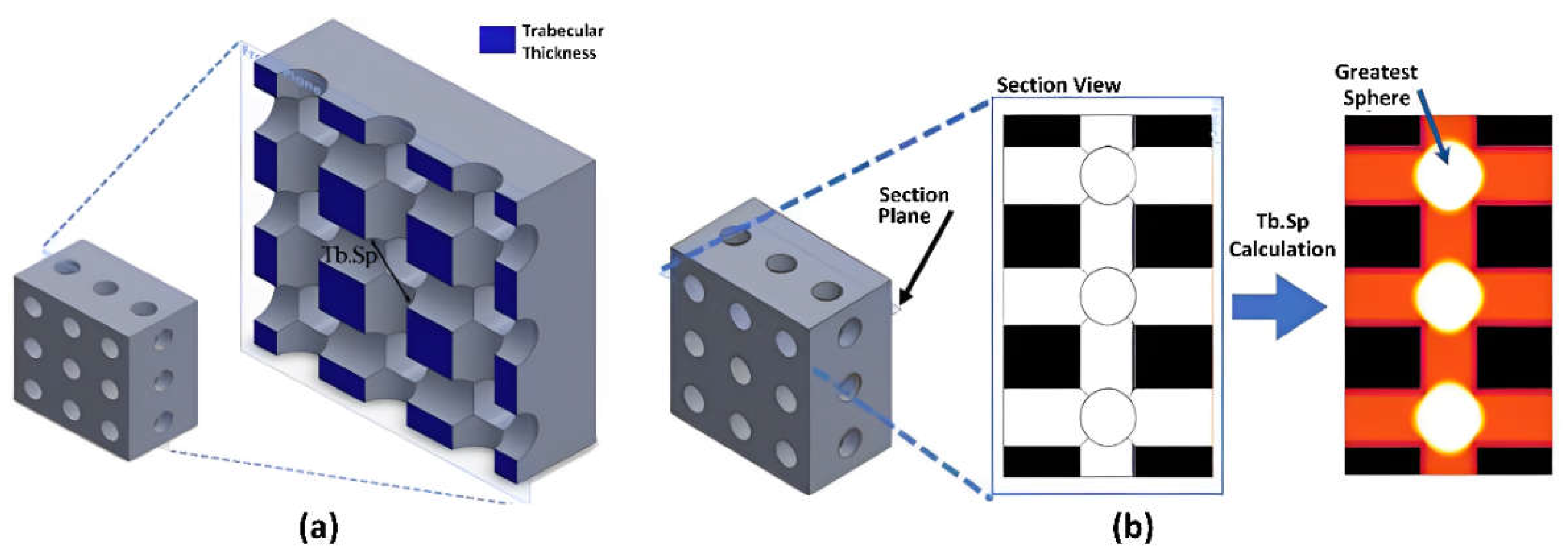
2.2. Morphological Characterization

Samples with a porosity of 41% were subjected to mechanical testing with compressive and monotonic specimens, for different degradation times (0 h, 24 h, 48 h, and 72 h) [14]. The specimen’s micro-CT images were cleaned and acquired (n = 12) using micro-CT Skyscan 1172 (Kontich, Belgium) at a resolution voxel 17.2 µm. Then, the image micro-CT was exported to ImageJ (Rasband, W.S., ImageJ US National Institutes of Health, Bethesda, MD, USA). These were then analyzed as the parameters of the degraded volume ratio of the surface area, the total volume (BV/TV), and the trabecular separation (Tb.Sp).
The local thickness of the chosen volumetric region (space) between the mean surface-to-surface trabecular, was used to calculate the trabecular separation (Tb.Sp). According to Figure 1, the diameter of the most important sphere corresponding to a certain space, is defined as Tb.Sp of a porous construction. The average number of reported Tb.Sp is the mean of the values of the measured Tb.Sp on random sites. The mean was calculated using ImageJ and BoneJ plugin apps, based on the trabecular thickness sections.

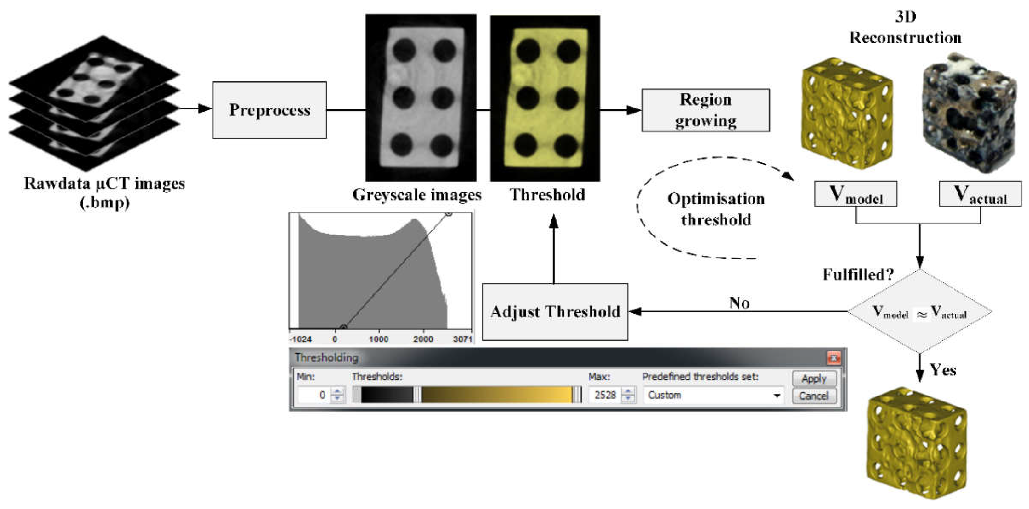
2.3. Segmentation Procedure

A deteriorated magnesium implant porosity specimen’s 3D model was created using grayscale micro-CT scans and the gathered 2D data, with a 0.172 mm cut thickness. As seen in Figure 2, the image is loaded into the Mimics program (Materialize, Leuven, Belgium), which converts it into a 3D model. To ensure that the specimen is enclosed with the fewest feasible black voxels, the intended region (ROI) is identified and shrunk to the greatest extent possible (i.e., air). A rectangular shape with dimensions of 4 mm × 6 mm and a height of 6 mm—which is greater than the cross-sectional area—determine the ROI.
The optimal threshold value is the segmented volume that is close to reality. When the V actual-V model difference is minimal. The optimal threshold value is achieved by manually repeating the segmentation in the Mimics software. The flowchart of the repeated or iterative segmentation, can be seen in Figure 2. an image of a porous magnesium specimen obtained from a CT scanner in the form of grayscale information. Gray value is a quantifiable relationship between each pixel assigned to the gray value and the material density of the scanned item. As a result, the Mimic software is capable of modeling any identifiable shape found in the scanned data, by combining the shades of gray. Segmenting the 2D data and building the 3D models are both possible. Thresholding is a sort of segmentation that creates a precise 3D model.
The specimen’s volume must match that of the real model. By dividing the scaffold’s mass by the density of the pure magnesium (1.74 g/cm3), the actual volume of the scaffold after degradation (V actual) may be determined from the experimental results. The volume of the model scaffold and the real volume is compared, during the validation step. To obtain a model volume that matches the real volume, the optimization step—which repeatedly adjusts the threshold value—is repeated if the prerequisites are not satisfied as explained in Table 2.

2.4. Monotonic Compression Test

A universal testing machine (The FastTrack 8874, Instron, Norwood, MA, USA) was used for the monotonic compression test. The mechanical properties of the porous Mg specimens were tested by compression using a 25-kN load cell at a strain rate of 0.005/s [14]. The fracture mechanics, strain life, and stress life are useful techniques for predicting the fatigue life in specimens. The strain-based approach works well for forecasting a low cycle fatigue. Cyclic loading with strain control may also be done on universal testing equipment. Software with strain control was used to execute the cyclic loading (Wave MatrixTM Dynamic Material Testing Software, Instron, USA). The sample is compressed and loaded at a 2 Hz sine wave with a loading ratio of R = 0.1, under typical operating circumstances of 1–3 Hz [15,16].
The 3D model of porous magnesium is given homogeneous, isotropic, and plastic-elastic properties. Prior to the numerical analysis, Young’s modulus of magnesium solids was determined, by performing a pressure test using magnesium solids. The average value of the test results is then used as the input value for all numerical simulation samples carried out in this study. A Poisson ratio of 0.35 (see Table 3) was chosen to match the characteristics of thick trabecular bone tissue with a density of 1.74 g/cm3, and Young’s modulus was adjusted to be 3.5 GPa.

2.5. FEA-Based Modeling of the Fatigue

The finite element analysis (FEA) is a numerical approach to analyzing the mechanical behavior of porous scaffolds, such as the structural stiffness and fatigue life. The advantage of the FEA is that it is repeatable, and can be used to replicate actual tests. It can be used repeatedly to perform different types of simulations, and this is not possible with destructive experimental tests [17]. This capability opens up wide opportunities for scaffold samples to be optimized, such as in the morphological parameters.
A computer method known as the finite element analysis (FEA) is used to examine the mechanical properties of the porous scaffolds, such as their structural stiffness and fatigue life [18,19,20,21,22]. The benefit of the FEA is that it can be used to reproduce real experiments and is reproducible. For instance, comparable models may be used repeatedly to run various simulations, but destructive experimental tests cannot be employed for this. With this capacity, the scaffold samples may be improved in a variety of ways, including the morphological factors.

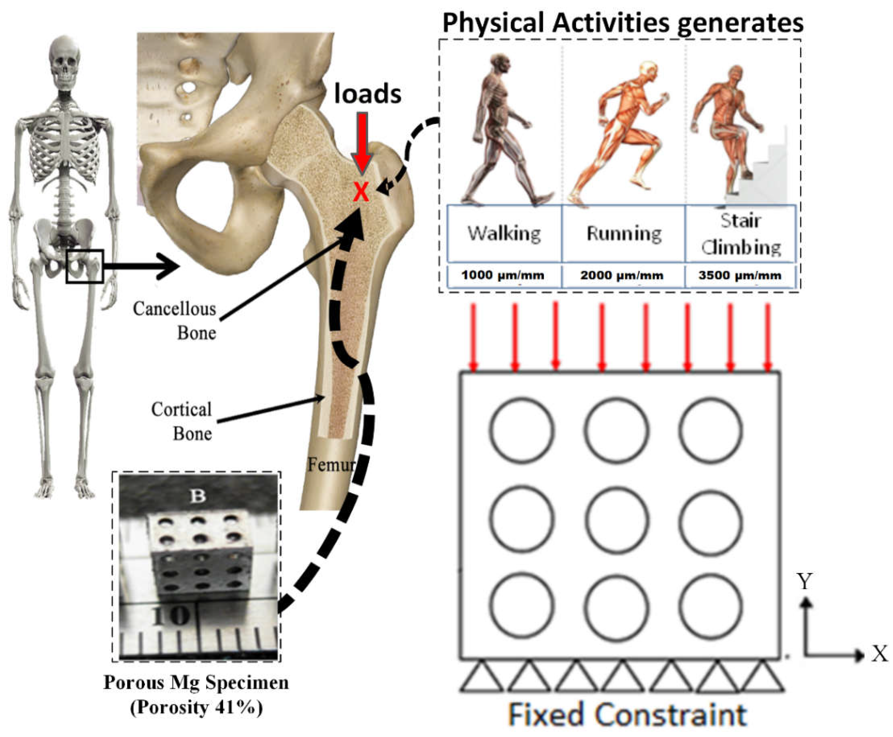
2.6. Boundary Condition and Material Input

Walking, running, and climbing stairs are examples of human physiological activities that put repetitive loads on the bones, resulting in a relatively small strain [23]. The stress distribution and fatigue life of the porous scaffold model are simulated in the next phase, using commercial software made by Comsol Multiphysics, Burlington, USA. Tetrahedral is an element found in the resultant three-dimensional numeric. Figure 3 displays the boundary conditions utilized in this simulation. To simulate the uniaxial loads, caused by the mechanical loads on bone, the defined displacement boundary conditions are defined on the top surface [24,25,26]. In addition, the surface normal shifts the zero-state displacement boundary.
This boundary condition restricts the nodes in the y direction but allows them to move freely in the x–z plane. The model is fixed in the y direction at the bottom, and a physiological-based strain of 1000–3500 µm/mm loads is applied to the upper surface, according to the variations in the bone mechanical loading [27]. The following is the behavior of the nonlinear elastic material magnesium; elasticity modulus 3500 MPa, Poisson’s ratio 0.35, and the kinematic tangent modulus 0.05E. The fatigue analysis was performed utilizing complete elastoplastic using a mix of Basquin and Coffin–Manson equations to forecast the fatigue life in low and high-cycle fatigue locations.

3. Results

3.1. Simulation Result Using The Fatigue Method

To analyze the structural fatigue, i.e., the fatigue cycle, the fatigue method’s simulation is required. The simulation is based on the human physiological activity from 0 to 3500 µm/mm. The simulation results will be graphed and viewed in two dimensions. Software Comsol Multiphysics 5.4 was used to predict the fatigue life in porous magnesium for the fatigue analysis studies. Sample porous magnesium, before being degraded by the human physiological activity, while walking, showed the highest fatigue cycle of 9.977 × 1025 and the lowest value of immersion time of 72 h was 2.05873 × 10⁵, so that the heavier the activities carried out by humans, the greater the potential for failure on the magnesium scaffold. The value of fatigue life in Sample porous magnesium has a significant effect on the variations in the loading. It can be seen in Figure 4 that the greater the load is given, the lower the fatigue value of the implant. The immersion time of each sample affects the fatigue life value on the implant, whereas the longer the immersion time, the fatigue life value decreases, due to the reduced surface area and specimen volume on the implant.

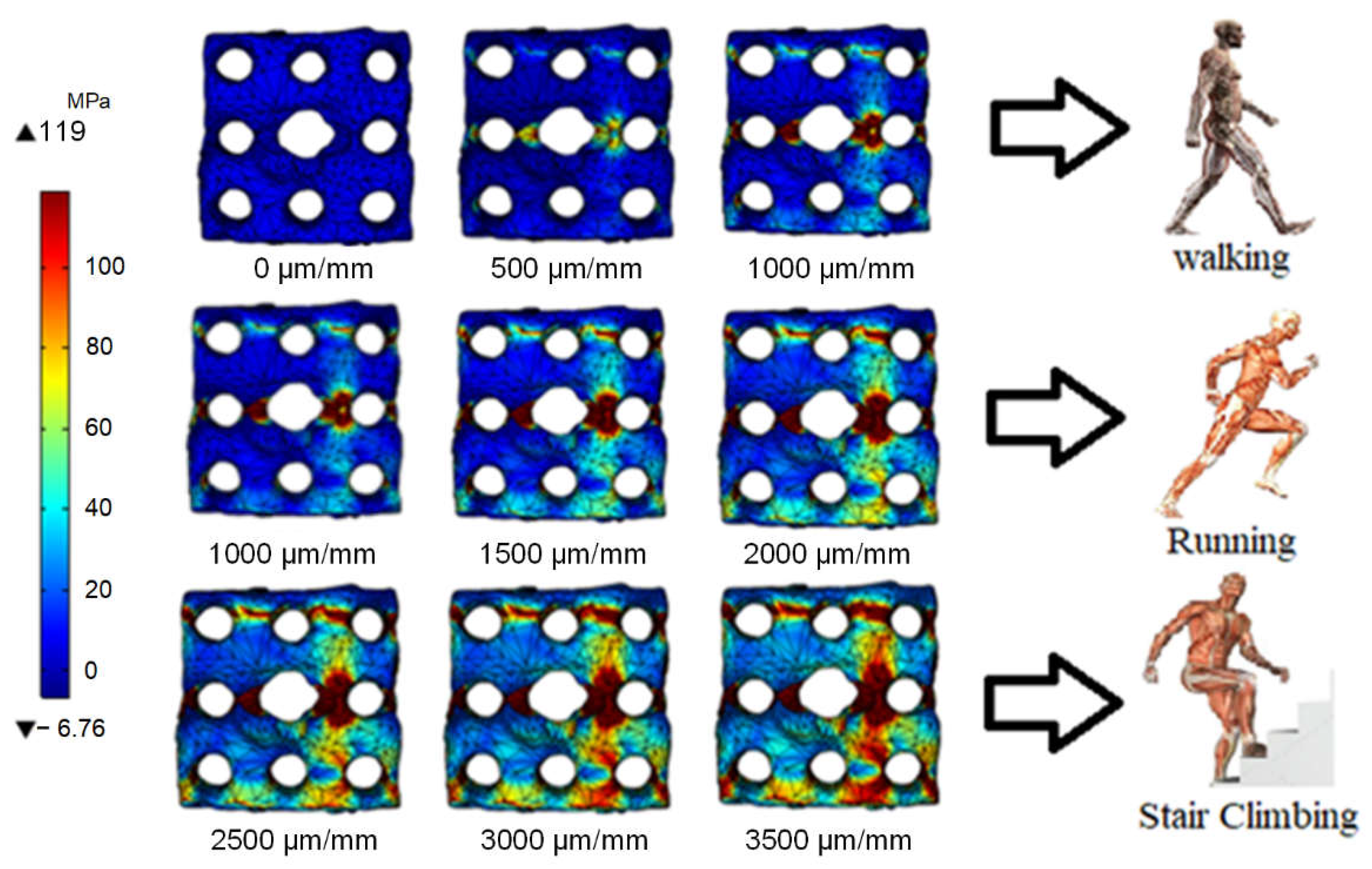
3.2. Stress Distribution of Porous Magnesium Implants on the Physiological Activity

Walking for 1000 µm/mm, running for 2000 µm/mm, and stair climbing for 3500 µm/mm are examples of physiological activity conditions. This loading causes different stress distributions on the porous magnesium sample. Then to find the strain using the equation ε = Δ l / l total, which ε is a strain, Δ l is displacement, and l total is the initial length of the bone scaffold. The contour plot of the stress distribution on the magnesium bone scaffold, during daily activities is shown in Figure 5. The stress distribution shows that the heavier the activity carried out on the porous magnesium, the greater the stress distribution that occurs.

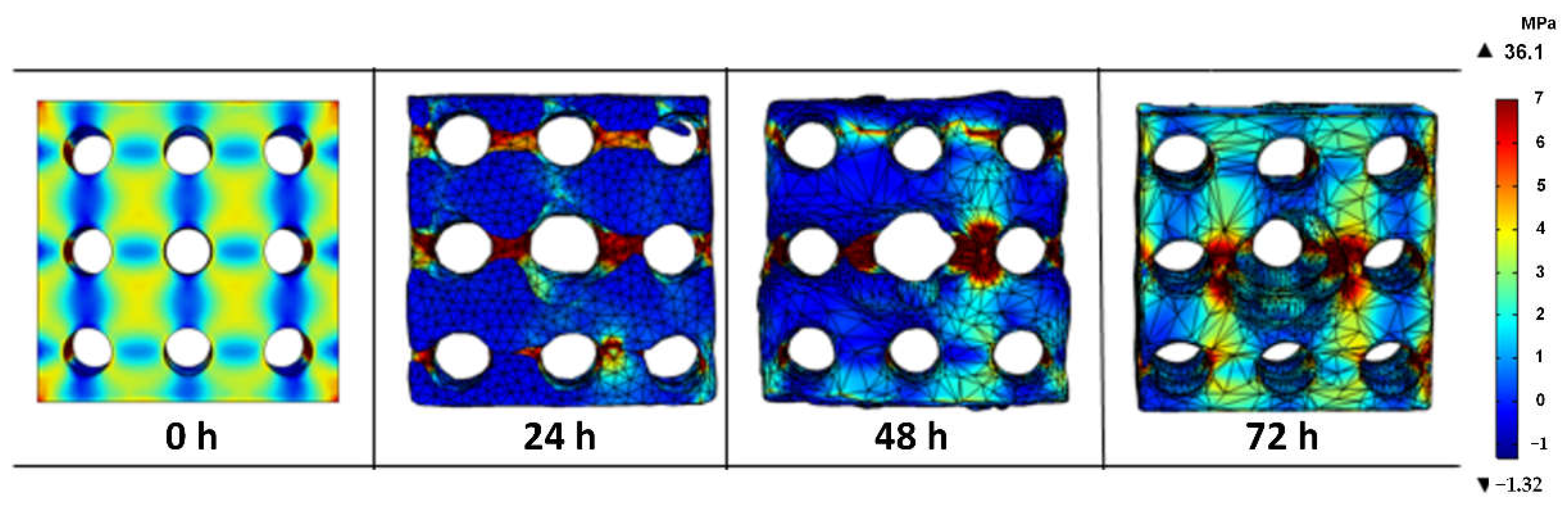
3.3. Stress Distribution on the Porous Magnesium Implant over Time

The stress distribution on our designed magnesium bone implants was analyzed using solid mechanics studies from the finite element method. The distribution of the stresses is represented by a color legend on the object, with red indicating a high distribution level and blue indicating a low distribution level. Figure 6 shows the contour plot of the porous magnesium stress distribution on the physiological activity of walking with the dynamic immersion times of 0, 24, 48, and 72 h. The immersion time and condition of the bone scaffold during daily activities affect the stress distribution. In magnesium before and after immersion for 24 h, the highest distribution occurred on the main support in the magnesium structure. The dynamic immersion that occurs in magnesium after 48 and 72 h of immersion, occurs in stress concentrations in certain parts. This stress concentration is due to the presence of a very thin porous magnesium structure, so this structure does not describe the overall stress distribution.

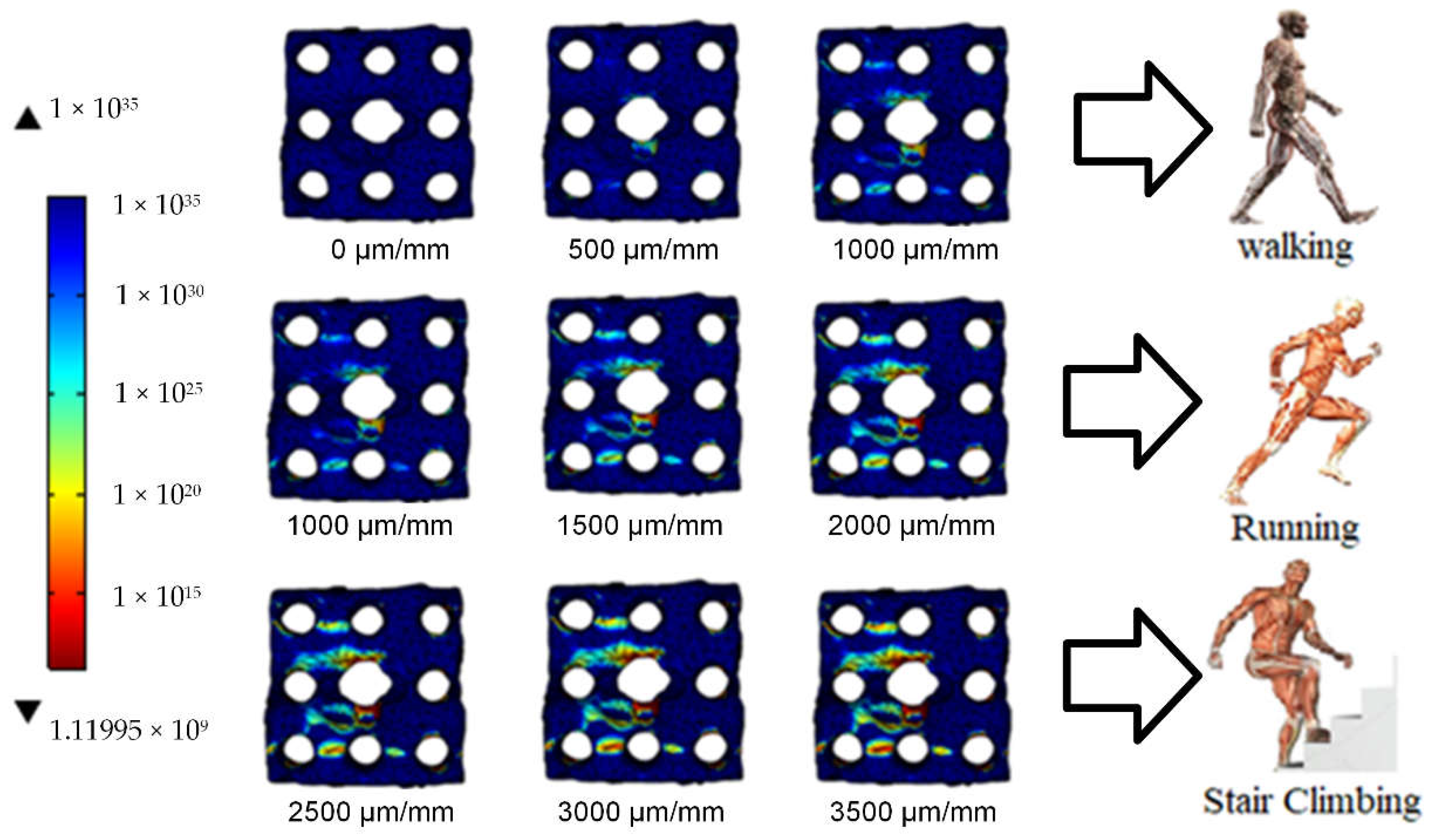
3.4. Fatigue Failure on the Porous Magnesium on Physiological Activity

The simulation results, as shown in Figure 7 on porous magnesium sample at 48 h, showed that human activities significantly affected the fatigue life of bone scaffold implants when do running activities, the value of fatigue life is low with a value of 1.11995 × 10⁹. The fatigue life of these implants increases significantly as the load activity decreases.

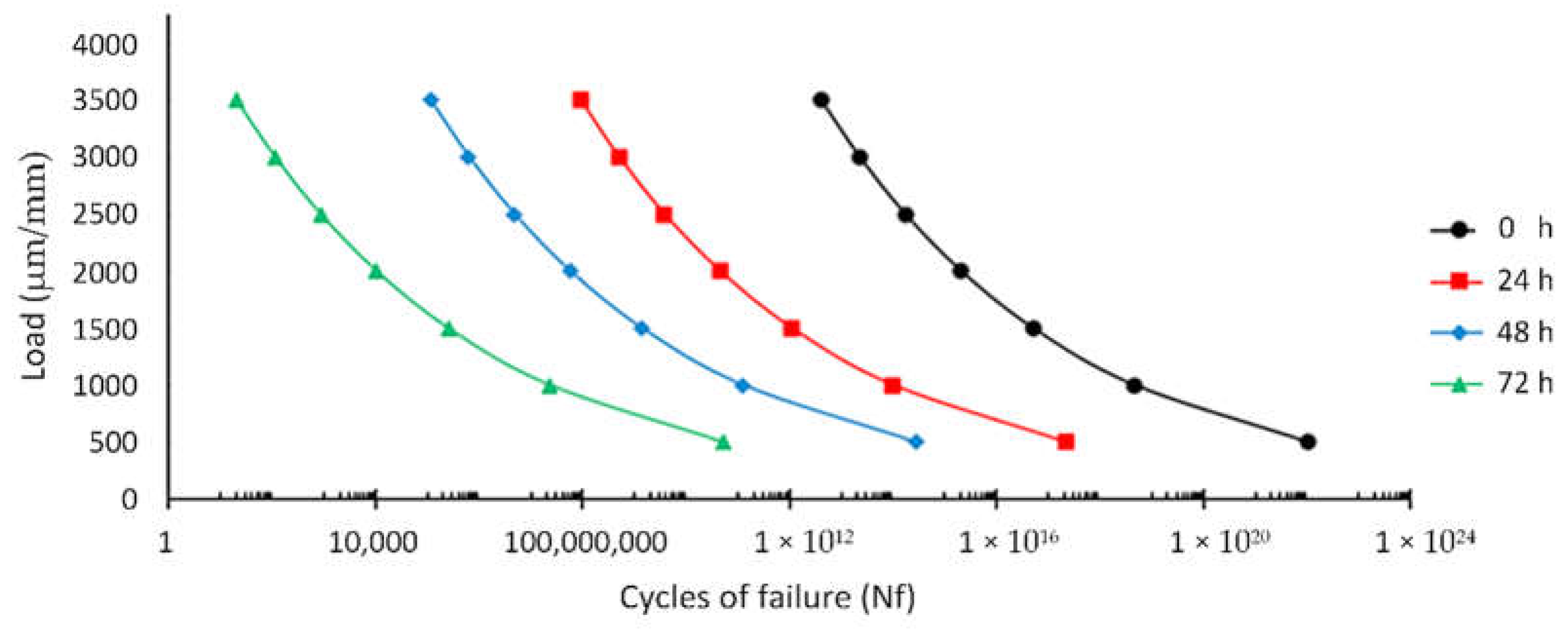
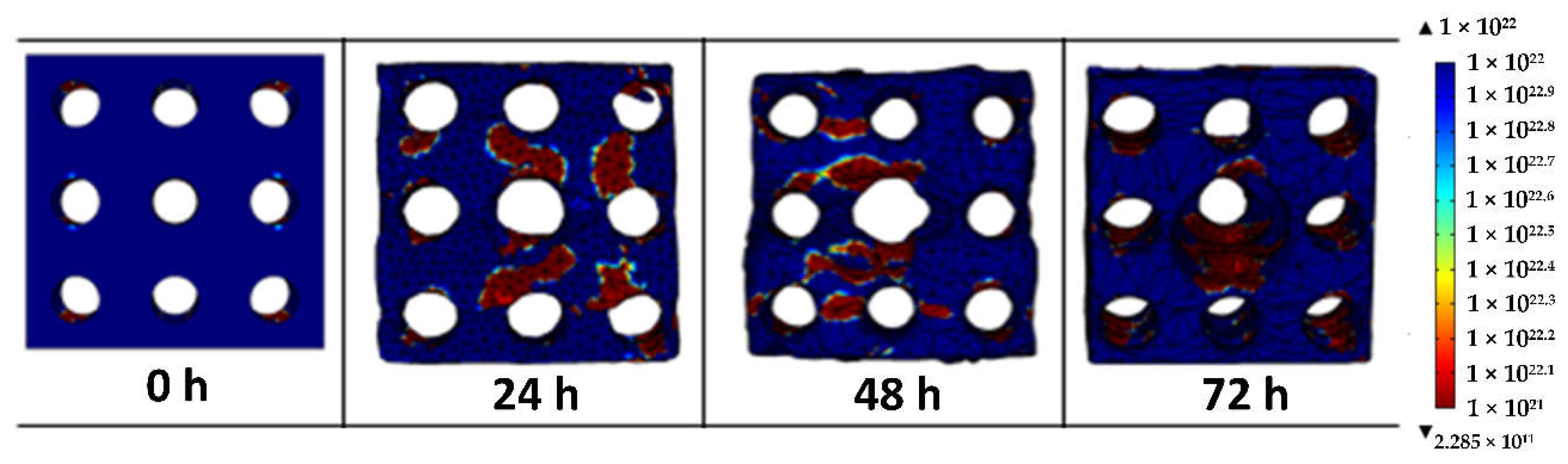
3.5. Fatigue Failure on the Porous Magnesium Implant over Time

The prediction of fatigue failure in porous magnesium was conducted using fatigue analysis software. Figure 8 shows the fatigue failure of the porous magnesium degradation rate before and after the dynamic immersion for 72 h. The fatigue life of porous magnesium will increase with the increasing surface area. This is because the longer the immersion time, the more surface will be degraded. So the surface area greatly affects the fatigue life. It illustrates the effective plastic strain contours of the porous magnesium at 0, 24, 48, and 72 h of dynamic immersion. The simulation on this porous magnesium obtained a maximum fatigue value of 4.5081 × 10²² and a minimum of 2.2856 × 1111 on the human physiological activities while walking. The effective plastic strain will decrease with the time of the dynamic immersion of porous magnesium. This decrease is indicated by the reduced surface area and the reduced volume of the specimen. With a reduced surface area and volume, there is an increase in stress in certain parts.

4. Discussion

Many researchers believe that porous magnesium can be used as a cancellous bone substitute because of its mechanical identity, which is nearly identical to cancellous bone properties. The nature of the cancellous bone environment encourages bone remodeling if a physiological activity is also involved. This action creates pressure differentials on the bone, which causes bone marrow to flow. Furthermore, the flow of bone marrow through the porous structure causes the mechanical load through mechanobiological signaling, to stimulate the bone remodeling process and maintain the bone quality [28]. When porous magnesium is implanted into human tissue, it will be exposed to the cancellous bone environment. As a result, it will receive a cyclic load when humans carry out physiological activities and degradation mechanisms during bone healing.
This research is essential for figuring out bone scaffolds’ fatigue life while still in living tissue. It relates to the porous magnesium scaffold implants’ shape and some cycles. Previous research has shown that because of the degradation, the dynamic immersion testing reduces the surface area of the bone scaffold [29]. The shape of the porous magnesium changes dramatically as the dynamic immersion time increases. The more time the sample spends in dynamic immersion, the more surface area it loses to degradation. These changes are significant for figuring out how well the bone scaffold will work as a load-bearing surface as the new bone grows [30].
It is complicated to predict the lifetime of the scaffold when it is embedded in the bone. At this point, the scaffold will fall because of a phenomenon called “degradation,” in which the scaffold’s struts weaken because of the cyclic load they have been supporting. Therefore, researchers performed a dynamic immersion test, after which the after-degradation model was obtained and reconstructed using a micro-CT scanner [31]. This method is a non-destructive way to look at the microarchitecture of applications for bone tissue engineering. For example, an orthopedic doctor can monitor the morphology after implanting the bone. Furthermore, by scanning the micro-CT and using finite element analysis (FEA), the mechanical behavior and fatigue of the scaffold can be analyzed [32]. The initial values for the boundary condition that were used to find the parameter values for the fatigue life simulation are shown in Table 3.
In this study, the material used is a non-ferrous metal type, so it does not have fatigue or no endurance limit. In the end, it will fail if it experiences sufficient stress cycles [33]. It can be seen in Figure 4 that the cycles of failure (Nf) increase when the given strain is low. The fatigue life analysis in this study uses strain life as a control. Mechanical changes in the material are indicated by a decrease in the modulus of the material under plastic strain [34]. Several parameters affect the fatigue life: the applied load, surface area, and fatigue [35]. The applied load significantly affects the fatigue life of porous magnesium. Loading will affect the stress of the material; the greater the load applied, the higher the stress that occurs, so the fatigue life in porous magnesium will be faster, as shown in Figure 8. A porous magnesium implant with a low strain rate will have a better fatigue cycle value, so it takes longer for the implant to fail.
Looking at how stress is distributed in bone scaffolds, is essential because it gives us new information about how structures will fail. Theoretically, a structure with a high porosity will also cause a higher stress distribution, which can be seen in Figure 8. The distribution of stress before and after the dynamic immersion for 24 h did not significantly increase in stress distribution. The missing surface area is not too significant, but the stress distribution has increased significantly when the dynamic immersion is carried out for 72 h. The highest stress distribution is focused on the support (struts) of the bone scaffold. It is because these struts have a smaller surface area.
The type of fracture of porous magnesium under variation of the load, as shown in Figure 7, indicates the type of global fracture. FEA analyses of the magnesium structures show that porous magnesium sample has cracks everywhere. This type of fracture mode may be attributed to the material’s ductility. Furthermore, a study found that most cancellous bone has global fractures. However, some cancellous bone samples still have oblique and local fractures. The sample with a higher percentage of pores has changed significantly because of the random way it has broken down. The fracture characteristic is similar to cancellous bone, which could represent the scaffold’s damage behavior once implanted to avoid different directional stress effects. The damage fracture may be due to stair climbing because it has a tremendous load.
Loading will affect the stress of the material; the greater the load applied, the higher the stress that occurs, so the fatigue life in porous magnesium will be faster, as shown in Figure 8. A porous magnesium implant with a low strain rate will have a better fatigue cycle value, so it takes longer for the implant to fail. Fatigue life in the bone scaffold dramatically affects the surface area, where the reduced surface area, due to degradation is faster as the bone scaffold fails, as shown in Figure 8. Bone scaffolds after degradation for 24, 48, and 72 h had a lower cycle of failure value than bone scaffolds that have not been put through dynamic immersion. It can be seen in Figure 8 that the effectiveness of plastic strains at a dynamic immersion of 72 h is higher, as stated by Basri et al. [14]. They state that the effect of the cyclic loading on a structure will decrease as immersion increases due to the degradation process.
The fatigue life graph can be obtained by the finite element simulation. This method can closely monitor new bone tissue that grows in the healing period. Furthermore, if the bone heals well, the failure of the bone scaffold can be kept to a minimum, so the patient does not have to have a second surgery. It can reduce patient costs, and the use of bone scaffolds allows patients to continue to do their desired activities, thereby reducing the time patients receive treatment and contributing to a better life.

5. Conclusions

This study demonstrates how human physiological activity levels and immersion duration have an impact on the fatigue life of porous magnesium. The fatigue life of the porous magnesium scaffold will decrease as the activity intensity and dynamic immersion time increase. The degree of deterioration has an impact on the fatigue life as well, and dynamic immersion testing of each porous magnesium sample revealed a considerable increase in the relative surface area loss. It is hoped that this study can improve the understanding of the fatigue life behavior of the porous magnesium implants when given the influence of human physiological activity and dynamic immersion time so that when the implant is implanted into bone tissue it can be predicted and controlled during the bone healing process.

Author Contributions

Conceptualization, A.S. and H.B.; methodology, A.T.P. and A.S.; software, R.U.P.; validation, H.C.; formal analysis, R.U.P. and A.T.P.; investigation, H.C.; resources, M.I.A.; data curation, R.U.P. and H.C.; writing—original draft preparation, R.U.P. and I.A.; writing—review and editing, H.B., M.I.A., A.S., and T.K.; visualization, A.T.P. and I.A.; supervision, H.B., A.S., and T.K.; project administration, M.I.A.; funding acquisition, H.B. and M.I.A. All authors have read and agreed to the published version of the manuscript.

Funding

The research publication of this article was funded by DIPA of Public Service Agency of Sriwijaya University 2022. SP DIPA-023.17.2.677515/2022, on 13 December 2021. In accordance with the Rector’s Decree Number: 0111/UN9.3.1/SK/2022, on 28 April 2022.

Institutional Review Board Statement

Not applicable.

Informed Consent Statement

Not applicable.

Data Availability Statement

The data presented in this study are available on request from the corresponding author.

Acknowledgments

We gratefully thank the Sriwijaya University, Pasundan University, Diponegoro University, Tridinanti University, Universiti Teknologi Malaysia and University of Malaya for their strong support of this study.

Conflicts of Interest

The authors declare no conflict of interest.

References

  1. Babuska, V.; Kasi, P.B.; Chocholata, P.; Wiesnerova, L.; Dvorakova, J.; Vrzakova, R.; Nekleionova, A.; Landsmann, L.; Kulda, V. Nanomaterials in Bone Regeneration. Appl. Sci. 2022, 12, 6793. [Google Scholar] [CrossRef]
  2. Rothweiler, R.M.; Zankovic, S.; Brandenburg, L.S.; Fuessinger, M.-A.; Gross, C.; Voss, P.J.; Metzger, M.-C. Feasibility of Implant Strain Measurement for Assessing Mandible Bone Regeneration. Micromachines 2022, 13, 1602. [Google Scholar] [CrossRef] [PubMed]
  3. Peña Fernández, M.; Black, C.; Dawson, J.; Gibbs, D.; Kanczler, J.; Oreffo, R.O.C.; Tozzi, G. Exploratory Full-Field Strain Analysis of Regenerated Bone Tissue from Osteoinductive Biomaterials. Materials 2020, 13, 168. [Google Scholar] [CrossRef] [PubMed] [Green Version]
  4. Noirrit-Esclassan, E.; Valera, M.-C.; Tremollieres, F.; Arnal, J.-F.; Lenfant, F.; Fontaine, C.; Vinel, A. Critical Role of Estrogens on Bone Homeostasis in Both Male and Female: From Physiology to Medical Implications. Int. J. Mol. Sci. 2021, 22, 1568. [Google Scholar] [CrossRef]
  5. Tavana, S.; Clark, J.N.; Newell, N.; Calder, J.D.; Hansen, U. In Vivo Deformation and Strain Measurements in Human Bone Using Digital Volume Correlation (DVC) and 3T Clinical MRI. Materials 2020, 13, 5354. [Google Scholar] [CrossRef]
  6. Semenova, I.P.; Modina, Y.M.; Stotskiy, A.G.; Polyakov, A.V.; Pesin, M.V. Fatigue Properties of Ti Alloys with an Ultrafine Grained Structure: Challenges and Achievements. Metals 2022, 12, 312. [Google Scholar] [CrossRef]
  7. Rajabinezhad, M.; Bahrami, A.; Mousavinia, M.; Seyedi, S.J.; Taheri, P. Corrosion-Fatigue Failure of Gas-Turbine Blades in an Oil and Gas Production Plant. Materials 2020, 13, 900. [Google Scholar] [CrossRef] [Green Version]
  8. Keramatian, A.; Bahrami, A.; Darougheh, A.H.; Zare, S. Root Cause Analysis of an Unexpected Brittle Failure in a Carbon Steel Slab. Eng. Fail. Anal. 2021, 122, 105205. [Google Scholar] [CrossRef]
  9. Mousavi Anijdan, S.H.; Sabzi, M. The Effect of Heat Treatment Process Parameters on Mechanical Properties, Precipitation, Fatigue Life, and Fracture Mode of an Austenitic Mn Hadfield Steel. J. Mater. Eng. Perform. 2018, 27, 5246–5253. [Google Scholar] [CrossRef]
  10. Salama, M.; Vaz, M.F.; Colaço, R.; Santos, C.; Carmezim, M. Biodegradable Iron and Porous Iron: Mechanical Properties, Degradation Behaviour, Manufacturing Routes and Biomedical Applications. J. Funct. Biomater. 2022, 13, 72. [Google Scholar] [CrossRef]
  11. Müller, M.; Šleger, V.; Kolář, V.; Hromasová, M.; Piš, D.; Mishra, R.K. Low-Cycle Fatigue Behavior of 3D-Printed PLA Reinforced with Natural Filler. Polymers 2022, 14, 1301. [Google Scholar] [CrossRef] [PubMed]
  12. Marcelino dos Santos, J.R.; Fernandes, M.F.; Velloso, V.M.d.O.; Voorwald, H.J.C. Fatigue Analysis of Threaded Components with Cd and Zn-Ni Anticorrosive Coatings. Metals 2021, 11, 1455. [Google Scholar] [CrossRef]
  13. Scacco, F.; Campagnolo, A.; Franceschi, M.; Meneghetti, G. Strain-Controlled Fatigue Behavior of a Nodular Cast Iron in Real Off-Highway Axles: Effects of Casting Skin and Strain Ratio. Metals 2022, 12, 426. [Google Scholar] [CrossRef]
  14. Basri, H.; Prakoso, A.T.; Sulong, M.A.; Md Saad, A.P.; Ramlee, M.H.; Agustin Wahjuningrum, D.; Sipaun, S.; Öchsner, A.; Syahrom, A. Mechanical Degradation Model of Porous Magnesium Scaffolds under Dynamic Immersion. Proc. Inst. Mech. Eng. Part L J. Mater. Des. Appl. 2020, 234, 175–185. [Google Scholar] [CrossRef]
  15. Fritton, S.P.; McLeod, K.J.; Rubin, C.T. Quantifying the Strain History of Bone: Spatial Uniformity and Self-Similarity of Low-Magnitude Strains. J. Biomech. 2000, 33, 317–325. [Google Scholar] [CrossRef]
  16. Lynch, M.E.; Fischbach, C. Biomechanical Forces in the Skeleton and Their Relevance to Bone Metastasis: Biology and Engineering Considerations. Adv. Drug Deliv. Rev. 2014, 79–80, 119–134. [Google Scholar] [CrossRef] [Green Version]
  17. Ammarullah, M.I.; Santoso, G.; Sugiharto, S.; Supriyono, T.; Kurdi, O.; Tauviqirrahman, M.; Winarni, T.I.; Jamari, J. Tresca Stress Study of CoCrMo-on-CoCrMo Bearings Based on Body Mass Index Using 2D Computational Model. J. Tribol. 2022, 33, 31–38. [Google Scholar]
  18. Roda-Casanova, V.; Pérez-González, A.; Zubizarreta-Macho, Á.; Faus-Matoses, V. Fatigue Analysis of NiTi Rotary Endodontic Files through Finite Element Simulation: Effect of Root Canal Geometry on Fatigue Life. J. Clin. Med. 2021, 10, 5692. [Google Scholar] [CrossRef]
  19. Bashiri, A.H.; Alshoaibi, A.M. Adaptive Finite Element Prediction of Fatigue Life and Crack Path in 2D Structural Components. Metals 2020, 10, 1316. [Google Scholar] [CrossRef]
  20. Kashyzadeh, K.R.; Rahimian Koloor, S.S.; Omidi Bidgoli, M.; Petrů, M.; Amiri Asfarjani, A. An Optimum Fatigue Design of Polymer Composite Compressed Natural Gas Tank Using Hybrid Finite Element-Response Surface Methods. Polymers 2021, 13, 483. [Google Scholar] [CrossRef]
  21. Shah, G.J.; Nazir, A.; Lin, S.-C.; Jeng, J.-Y. Design for Additive Manufacturing and Investigation of Surface-Based Lattice Structures for Buckling Properties Using Experimental and Finite Element Methods. Materials 2022, 15, 4037. [Google Scholar] [CrossRef] [PubMed]
  22. Gibbons, M.M.; Chen, D.A. Bio-Inspired Sutures: Using Finite Element Analysis to Parameterize the Mechanical Response of Dovetail Sutures in Simulated Bending of a Curved Structure. Biomimetics 2022, 7, 82. [Google Scholar] [CrossRef] [PubMed]
  23. Thompson, W.R.; Rubin, C.T.; Rubin, J. Mechanical Regulation of Signaling Pathways in Bone. Gene 2012, 503, 179–193. [Google Scholar] [CrossRef] [PubMed] [Green Version]
  24. Shokry, A.; Mulki, H.; Kharmanda, G. A Logarithmic Formulation for Anisotropic Behavior Characterization of Bovine Cortical Bone Tissue in Long Bones Undergoing Uniaxial Compression at Different Speeds. Materials 2021, 14, 5045. [Google Scholar] [CrossRef]
  25. Ahlhelm, M.; Latorre, S.H.; Mayr, H.O.; Storch, C.; Freytag, C.; Werner, D.; Schwarzer-Fischer, E.; Seidenstücker, M. Mechanically Stable β-TCP Structural Hybrid Scaffolds for Potential Bone Replacement. J. Compos. Sci. 2021, 5, 281. [Google Scholar] [CrossRef]
  26. Chang, Z.; Zhang, H.; Schlangen, E.; Šavija, B. Lattice Fracture Model for Concrete Fracture Revisited: Calibration and Validation. Appl. Sci. 2020, 10, 4822. [Google Scholar] [CrossRef]
  27. Zargarian, A.; Esfahanian, M.; Kadkhodapour, J.; Ziaei-Rad, S. Numerical Simulation of the Fatigue Behavior of Additive Manufactured Titanium Porous Lattice Structures. Mater. Sci. Eng. C 2016, 60, 339–347. [Google Scholar] [CrossRef]
  28. Weinkamer, R.; Eberl, C.; Fratzl, P. Mechanoregulation of Bone Remodeling and Healing as Inspiration for Self-Repair in Materials. Biomimetics 2019, 4, 46. [Google Scholar] [CrossRef] [Green Version]
  29. Silva, C.L.P.; Camara, M.A.; Hohenwarter, A.; Figueiredo, R.B. Mechanical Behavior and In Vitro Corrosion of Cubic Scaffolds of Pure Magnesium Processed by Severe Plastic Deformation. Metals 2021, 11, 1791. [Google Scholar] [CrossRef]
  30. Sakthiabirami, K.; Soundharrajan, V.; Kang, J.-H.; Yang, Y.P.; Park, S.-W. Three-Dimensional Zirconia-Based Scaffolds for Load-Bearing Bone-Regeneration Applications: Prospects and Challenges. Materials 2021, 14, 3207. [Google Scholar] [CrossRef]
  31. Olăreț, E.; Stancu, I.-C.; Iovu, H.; Serafim, A. Computed Tomography as a Characterization Tool for Engineered Scaffolds with Biomedical Applications. Materials 2021, 14, 6763. [Google Scholar] [CrossRef] [PubMed]
  32. Naghavi, S.A.; Tamaddon, M.; Marghoub, A.; Wang, K.; Babamiri, B.B.; Hazeli, K.; Xu, W.; Lu, X.; Sun, C.; Wang, L.; et al. Mechanical Characterisation and Numerical Modelling of TPMS-Based Gyroid and Diamond Ti6Al4V Scaffolds for Bone Implants: An Integrated Approach for Translational Consideration. Bioengineering 2022, 9, 504. [Google Scholar] [CrossRef] [PubMed]
  33. Madhukarϯ, S.; Harshith Reddy, B.R.; Kumar, G.A.; Naikϯ, R.P. A Study on Improvement of Fatigue Life of Materials by Surface Coatings. Int. J. Curr. Eng. Technol. 2018, 8, 5–9. [Google Scholar] [CrossRef] [Green Version]
  34. Li, N.; Tian, Y.; Ma, B.; Hu, D. Experimental Investigation of Water-Retaining and Mechanical Behaviors of Unbound Granular Materials under Infiltration. Sustainability 2022, 14, 1174. [Google Scholar] [CrossRef]
  35. Li, Y.; Retraint, D.; Gao, P.; Xue, H.; Gao, T.; Sun, Z. Effect of Surface Mechanical Attrition Treatment on Torsional Fatigue Properties of a 7075 Aluminum Alloy. Metals 2022, 12, 785. [Google Scholar] [CrossRef]
Figure 1. Detail morphology of the porous magnesium scaffold: (a) Cross-sectional; (b) Tb.Sp.
Sustainability 15 00823 g001
Figure 2. Flow chart of the iterative segmentation, based on the thresholding optimization.
Sustainability 15 00823 g002
Figure 3. Boundary conditions schematic diagram.
Sustainability 15 00823 g003
Figure 4. Load (μm/mm) vs Cycles of failure (Nf).
Sustainability 15 00823 g004
Figure 5. Comparison plot of the porous magnesium stress distribution contour on human physiological activity, after 48 h of immersion.
Sustainability 15 00823 g005
Figure 6. Comparison of the porous magnesium stress distribution contour plots on the walking activity after the dynamic immersion times of 0, 24, 48, and 72 h.
Sustainability 15 00823 g006
Figure 7. On human physiological activity, the effective contour plot of porous magnesium plastic strain on sample porous magnesium with a 48-h immersion time.
Sustainability 15 00823 g007
Figure 8. Effective plot contour of porous magnesium plastic strain on walking activity for dynamic immersion durations of 0, 24, 48, and 72 hours.
Sustainability 15 00823 g008
Table 1. A summary of the specific geometry for the porous magnesium specimens.
PorositySurface AreaVolumeMass per Surface Area
41%209.81 mm244.57 mm3 0.34 kg/m2
Table 2. A summary of the specific geometry for the porous magnesium specimens [14].
IterativeThreshold Values (HU)Volume of Mimics Model (mm3)Actual Volume (mm3)Percentage Error (%)
#1−59250.5839.8926.82
#2−40746.3239.8916.13
#3041.6139.894.33
#411040.5739.891.72
#515040.1939.890.77
#618639.8739.890.03
#720039.7339.890.39
#824039.4139.891.19
#926739.1639.891.82
#1030038.8939.892.49
#11107632.5339.8918.53
#12141628.8339.89 27.72
Table 3. Magnesium’s mechanical characteristics when used in the FEA.
Mechanical PropertiesMagnesium
Monotonic Properties
  Young’s modulus, E (GPa)3.5
  Poisson’s ratio0.35
   Yield   strength ,   σ y   (MPa)147
   Kinematic   tan gent   modulus ,   K T k i n 0.05E
Fatigue Properties
   Fatigue   ductility   coefficient ,   ε f 0.425
   Fatigue   ductility   exponent ,   c −1.3
   Fatigue   strength   coefficient ,   σ f (MPa)180
   Fatigue   strength   exponent ,   b −0.09
Disclaimer/Publisher’s Note: The statements, opinions and data contained in all publications are solely those of the individual author(s) and contributor(s) and not of MDPI and/or the editor(s). MDPI and/or the editor(s) disclaim responsibility for any injury to people or property resulting from any ideas, methods, instructions or products referred to in the content.

