Article

Ground Reaction of Lightly Overconsolidated Subsoil in Reinforced Piled Embankment under Cyclic Loads

1
Department of Road and Bridge Engineering, School of Civil Engineering and Architecture, Hubei University of Technology, Wuhan 430068, China
2
Key Laboratory of Concrete and Prestressed Concrete Structures of Ministry of Education, Southeast University, Nanjing 210096, China
3
School of Civil Engineering, Zhejiang University of Technology, Hangzhou 310014, China
*
Author to whom correspondence should be addressed.
Sustainability 2023, 15(1), 619; https://doi.org/10.3390/su15010619
Submission received: 5 October 2022 / Revised: 6 December 2022 / Accepted: 24 December 2022 / Published: 29 December 2022

Abstract

:
Subsoil support is generally ignored in the design of reinforced piled embankments, resulting in a very conservative design for settlement control. This design philosophy may lead to an unnecessary increase in construction costs, especially for embankments constructed over subsoil of medium and high compressibility (i.e., compression index of subsoil larger than 0.2). This paper presents the ground reaction of lightly overconsolidated subsoil in a reinforced piled embankment subjected to cyclic loads for the purpose of investigating the general behavior of lightly overconsolidated subsoil, and it promotes the sustainable development of piled embankment technology. The ground reaction of subsoil under both static and cyclic loads was comprehensively analyzed in terms of settlement and incremental vertical stress, which exhibited approximately the same profile. However, the settlement of lightly overconsolidated subsoil under a cyclic load was 23% larger than that under a static load. A parametric study was then performed under cyclic loads, and the results showed that the vertical stress carried by the subsoil was the most sensitive to the pile spacing amongst all the parameters considered in this paper. The analysis demonstrated an approximately 88% increase in stress when spacing was enlarged from 2.0 to 3.0 m. Finally, a modified analytical method for the ground reaction of lightly overconsolidated subsoil under cyclic loads was presented, and it showed reasonable agreement with the numerical simulation, particularly for relatively low geogrid stiffnesses, low embankment height (<6.5 m), and small pile spacing (e.g., 2–3 m center to center).

1. Introduction

Over recent decades, the transportation system, such as highways and railways, has significantly expanded due to the increase in traffic volume. The serviceability behavior of highway assets entails strict requirements for the embankment design and construction, particularly in areas where soft soils exist. In order to avoid the potential problems that are generally caused in embankments overlying soft soils, such as excess total and differential settlements, low bearing capacity, and slope instability, reinforced piled embankments have been widely adopted and are extensively investigated in the literature [1,2,3,4,5,6,7,8,9,10].
The load transfer mechanism of reinforced piled embankments is much more complicated, including the arching effect and membrane effect [11,12,13,14,15,16,17,18,19]. The former references relate to the part of the embankment load directly transferred to the piles, and the remaining embankment load is carried by the subsoil and geosynthetic reinforcement, while the latter is defined as the load deformation coordination of the deflected reinforcement under the effect of vertical loads. Regarding to the soil arching effect, significant research has been conducted in the literature [20,21,22,23,24,25,26,27,28,29,30]. As for the membrane effect, some guidelines have been proposed to directly determine the maximum tensile force and strain of the reinforcement, which may significantly influence the serviceability behavior of the reinforced piled embankment [12,14,15,31,32,33,34,35,36,37,38,39,40]. The research provides significant guidance regarding the design and construction of reinforced piled embankments; however, the deformation of geosynthetic reinforcements is usually assumed as an arc or catenary, without considering the subsoil support. This may lead to a very conservative design for the settlement control of the reinforced piled embankment, resulting in unnecessary increases in construction costs, especially for the embankments constructed over subsoil of medium compressibility [17,19,23,37]. Hu et al. [41] proposed a design chart for the analysis of the maximum strain in the reinforcement of geogrid-reinforced piled embankments (GRPEs) by considering the stress history of the subsoil with different overconsolidation ratios (OCRs) for assessing the settlement of the supporting subsoil.
Recently, more and more attention has been paid to the dynamic behavior of reinforced piled embankments [42,43,44,45,46,47,48,49,50,51]. However, the ground reaction of the subsoil in reinforced piled embankments under cyclic loads has not yet been fully understood, especially for lightly overconsolidated subsoil. Different from normally consolidated subsoil, during the consolidation process, lightly overconsolidated subsoil undergoes a change in phase from an overconsolidated state to a normally consolidated state due to the increase in effective stress beyond the preconsolidation stress [52]. Moreover, the research conducted to date has been emphasized primarily on the dynamic behavior of piled embankments, while the consolidation of the subsoil is generally neglected due to the complexity of the procedure. This analysis usually results in poor correlations when evaluating the load transfer and settlement of piled embankments subjected to cyclic loads. In fact, when the cyclic loads would travel along the highway’s piled embankment, the water pressure would be constantly generated and dissipated, leading to a further complex fluid–solid coupling effect occurring in the subsoil, which should be further investigated to obtain an insight into the general behavior of the ground reaction of lightly overconsolidated subsoil [53].
This paper presents a numerical simulation of the ground reaction of lightly overconsolidated subsoil under cyclic loads, in which the subsoil consolidation is considered. Several finite element (FE) models for reinforced piled embankments are developed, by which the profiles of the settlement and vertical stress increment of the subsoil are comprehensively analyzed to provide an insight into the general behavior of the lightly overconsolidated subsoil. A parametric study is then performed to investigate the influence of the geometries and properties of piled embankments under cyclic loads on the ground reaction of lightly overconsolidated subsoil. Finally, the analytical method proposed by Zhuang and Wang [52] for the prediction of the dynamic behavior of lightly overconsolidated subsoil, incorporating cyclic loads induced under dynamic stress, is presented and compared with the results of our numerical simulations.

2. Numerical Simulation

2.1. General Description

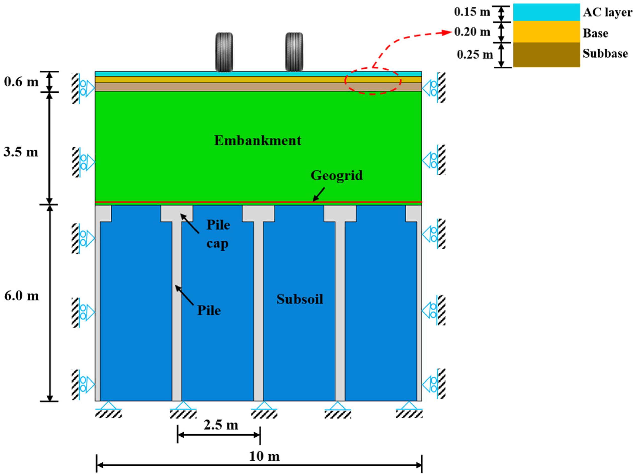
A hypothetical highway piled embankment, shown in Figure 1a, is considered in this paper. The piled embankment, including a 0.6 m pavement, was assumed to be constructed over a soft clay layer with a constant thickness of 6.0 m, below which exists a rigid layer. The 0.3 m wide, square-sharped concrete piles were arranged in a square pattern, as shown in Figure 1b. To enhance the efficiency of the arching effect, a pile cap with a width of 1.0 m and thickness of 0.5 m was assumed to be concreted at the top of the pile, whose top surface was at the same level as the embankment–subsoil interface (Figure 1a). A layer of the geogrid was arranged at a height of 0.1 m above the base of the embankment. In order to comprehensively investigate the influence of the parameters that may affect the contribution of subsoil in reinforced piled embankments, the geometries (pile spacing s, and embankment height h), material properties (elastic modulus E, friction angle φ, dilation angle Ψ and cohesion c of embankment, geogrid stiffness J, and compression index Cc of the lightly overconsolidated subsoil) were changed to cover a broad range, as shown in Table 1 [52].
Due to symmetry, a simplified model with twenty piles and their surrounding area (the dotted square domain in Figure 1b) was obtained using the finite element (FE) package ‘ABAQUS’ (version 6.12), whose elevation view is shown in Figure 2. This arrangement details the model geometry and boundary conditions, which are clearly illustrated. The approach adopted in the numerical simulation was the same as that of Zhuang and Wang [52] but explicitly focused on the behavior of the overconsolidated subsoil. It should be noted that the plan view of the FE model has a size of 4 s × 4 s, in which s is the pile center–center spacing and is considered as 2.0, 2.5, and 3.0 m herein. As for the boundary condition, the displacement at the base of the model was restrained, and the lateral displacement at four vertical planes was restrained as well.

2.2. Constitutive Models

The embankment filling in this work is simulated by a simple elastic–perfectly plastic (Mohr–Coulomb) model, in accordance with that in Zhuang and Wang’s study [52]. Since the strength and stiffness of the pavement (AC layer, base, and subbase), geogrid, and pile are significantly larger than those of the embankment fill and subsoil, they are represented as linear elastic materials, ignoring their stress-dependent stiffness behavior characteristics. The interface with the embankment material is modeled as ‘rough’ (i.e., φi = φ’). Based on the investigation of Potyondy [54], the interaction between the pile and subsoil is simulated as ‘penalty’, with the interface friction angle (φi) assumed as φi = 0.7 φ’, where φ’ is the subsoil’s friction angle.
The soft subsoil is modeled using Modified Cam Clay (MCC), and the parameters are shown in Table 1. In the Modified Cam Clay (MCC) model, the required parameter λ is equal to Cc divided by 2.3, and κ is assumed equal to 0.1 times λ [34]. The 6.0 m-thick subsoil was assumed to be saturated throughout, and the water table was situated at the subsoil surface, with hydrostatic variation with depth (prior to the generation of any excess pore pressure due to embankment construction). The soft clay was considered as slightly overconsolidated subsoil, which had experienced a ‘preconsolidation stress’ (Δσvp) equal to 5, 10, or 20 kN/m2 larger than the current vertical effective stress [35]. This caused the soil to be ‘lightly overconsolidated’, with an overconsolidation ratio of 2.4 at 1.0 m depth, reducing to 1.5 at 3.0 m depth and 1.2 at 6 m depth.
For elastic reloading up to the point of preconsolidation stress and one-dimensional vertical strain, the corresponding stiffness E0 can be obtained in terms of the ‘inherent’ properties κ and Poisson’s ratio. This implied an approximately linear profile with depth in the subsoil (z), which could be characterized in Equation (1) according to the parameters used in Table 1 [34]:
E 0 = 0.20 + 0.235 z   ( MN / m 2 ,   z   in   m )
i.e., increasing from 0.20 MN/m2 at the soil surface to 1.61 MN/m2 at 6 m depth.
The permeability of the subsoil was not fundamentally important as such since the aim was to examine the effect of consolidation (‘before and after’) rather than the rate at which this occurred. In fact, it was convenient to specify the coefficient of consolidation (Cv) so that it did not vary with depth, and a value of 1 × 10⁻⁶ m2/s was used. It should be noted that in this paper, the coefficient of permeability was assumed to be the same in both directions (vertical and horizontal). Based on the in situ stiffness, the coefficient of permeability k was hence derived as 5 × 10⁻⁸ m/s at the top of the subsoil, reducing to 6 × 10⁻⁹ m/s at z = 6 m, and it was specified accordingly (varying with depth). It was estimated that the consolidation would be substantially complete after 2 years for two-way drainage in the 6 m-thick clay layer, and this was confirmed in the analyses.

2.3. Simulation Procedure

After the subsoil was fully consolidated, the cyclic loads shown in Figure 2 were then applied to the surface of the pavement by the subroutine DLOAD, which is simulated by a simple sine curve [52]:
P t = P 0 + P sin w t
where
P = M 0 μ w / r ( y ) w 2 ;   w = 2 π υ L
In the formulas, P0 is the static vehicle load and is taken as 50 kN/m2; M0 is the unsprung weight, which equals 250 N∙s2/m; μw/r(y) refers to the road roughness function and is assumed as 2 mm; v is the velocity of the cyclic loads, and v = 60 km/h is taken as a standard case; L is the geometric curve wavelength of the pavement and is considered as 6 m herein; and t is the duration time of load. Based on Huang [55], the cyclic loads in the numerical simulation were assumed to be uniformly distributed with the rectangular-shaped contact area of 0.30 m × 0.24 m and two wheels with spacing of 2.0 m, as shown in Figure 1b. The cyclic loads were assumed to be periodically moved along the travel direction, and the cyclic number was 100.
A full FE model for the reinforced piled embankment shown in Figure 1 has also been developed for validation against the simplified model illustrated above. The comparison between the full model and the simplified model exhibited approximately the same results, with the maximum difference in terms of the vertical stress carried by the subsoil within 10%. In reality, the full FE model may be very complicated due to the simulation of the full geometry, together with the complex interaction between different components of the piled embankment, leading to high requirements for the computing and calculation costs compared with the simplified FE model. As a result, the simplified FE model was used in simulating the ground reaction of lightly overconsolidated subsoil in reinforced piled embankments under cyclic loads.

3. Ground Reaction of Lightly Overconsolidated Subsoil

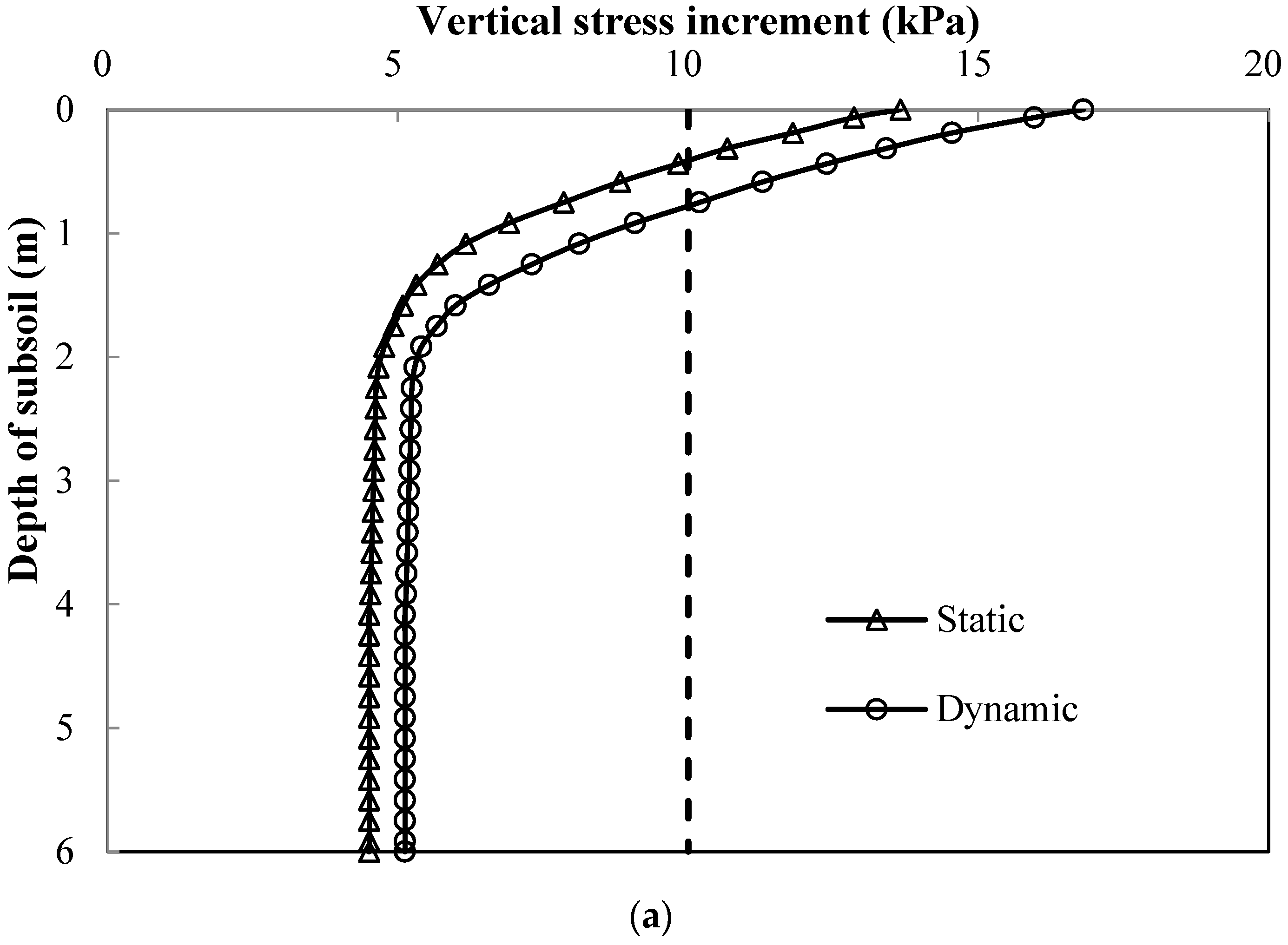
As shown in Figure 3, the typical profiles with the depth of the lightly overconsolidated subsoil (z) at the end of an analysis both under static and cyclic loads (s = 2.5 m, h = 3.5 m, J = 3.0 MN/m, v = 60 km/h, Cc = 0.3) were comprehensively investigated. It should be noted that the excess pore water pressure due to embankment construction was allowed to dissipate completely during the consolidation phase; the increments in total and effective stress in the subsoil were therefore equal. The profiles of the vertical stress increment (Δσv, compared to the initial in situ state) under static and cyclic loads captured approximately the same trend, as illustrated in Figure 3a. The increment in vertical stress Δσv was practically constant (with values of 4.5 kPa under static load and 5.1 kPa under cyclic loads) for z > 2 m and was independent of location. As the surface of the soft subsoil was approached, Δσv increased quite dramatically for the situations under both static and cyclic loads. It appears that for z > 2 m, the behavior corresponds to one-dimensional (1-D) vertical settlement (with constant Δσv). Nearer to the surface of the subsoil, there is additional shear strain associated with non-uniform settlement, leading to the divergence (or redistribution) of Δσv, which increases at the center of the nearby pile caps (supporting the deformed geogrid). We also observed that the cyclic loads induced vertical stress that decreased with the depth of the subsoil, and they approached an approximately constant value at the depth of 2 m, indicating a critical depth for the influence of the cyclic loads in this analysis.
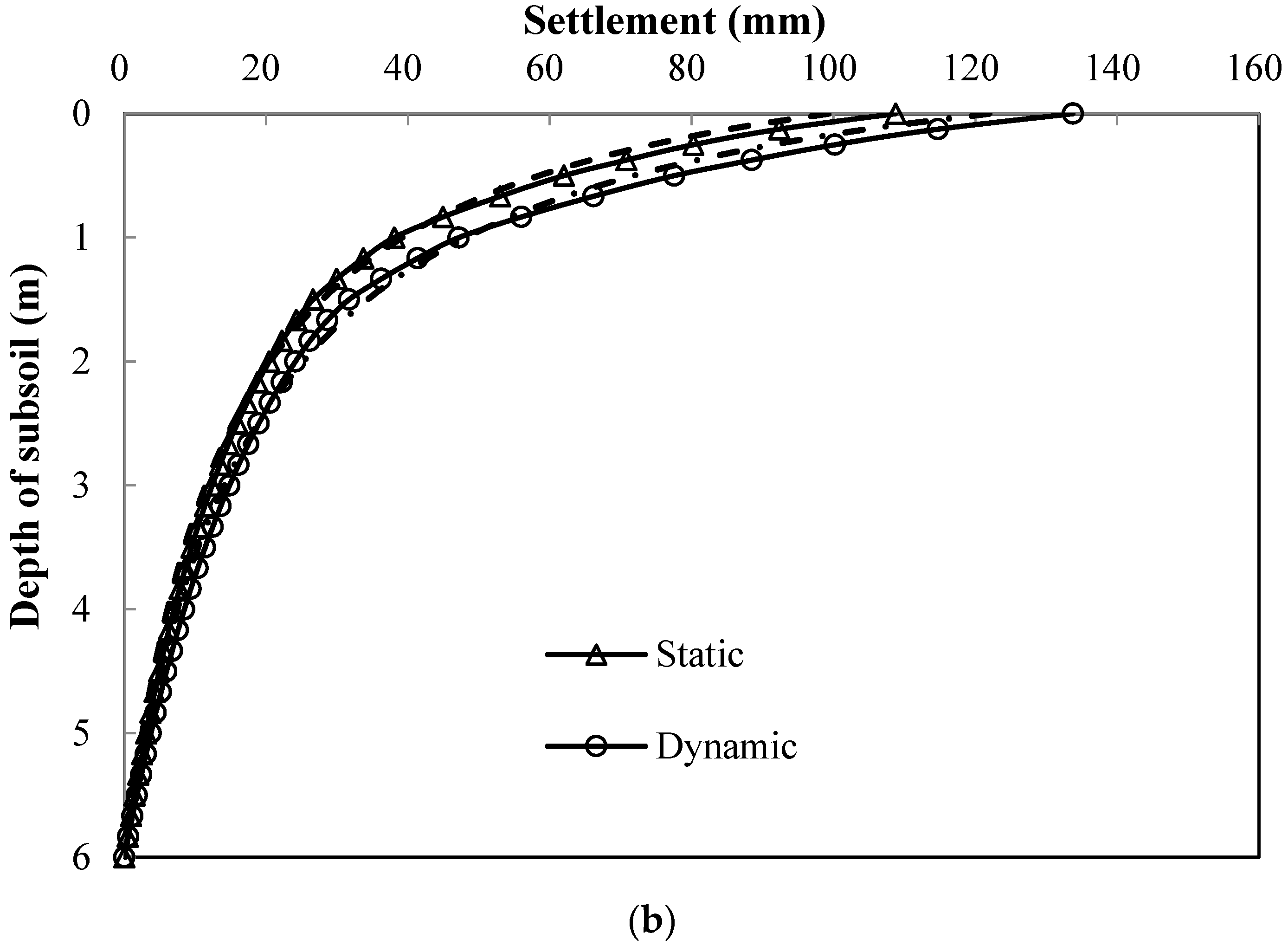
Figure 3b shows the corresponding settlement in lightly overconsolidated subsoil at the midpoint of the diagonal span. The ‘1-D prediction’ lines were obtained according to the pre-yield ‘elastic’ stiffness formulated in Equation (1). It should be noted that the vertical stress increment Δσv is 4.5 kPa under a static load and 5.1 kPa under cyclic loads, both of which are less than the preconsolidation stress Δσv = 10 kPa. For z > 2 m (and somewhat above this), the FE results showed excellent agreement with the prediction both under static and cyclic loads. Meanwhile, near the surface of the subsoil, the FE results were slightly larger than the ‘1-D prediction’, which corresponds to the additional effect of shear strain. We also observed that the surface settlement under cyclic loads was much larger than that under static loads, with an increment of approximately 23%.
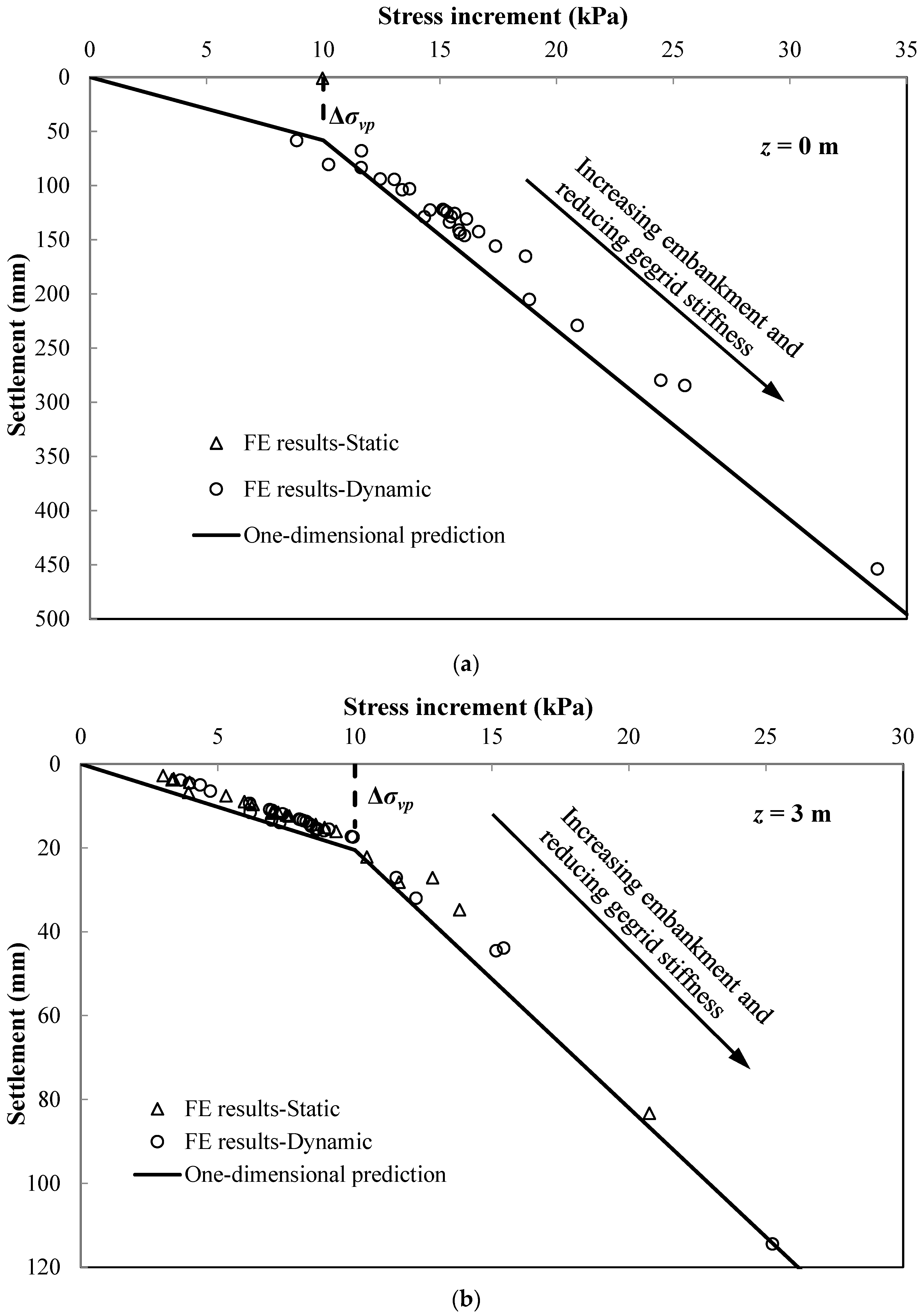
Figure 4 summarizes the maximum settlement (y) and vertical stress increment Δσv at the middle of a diagonal span for the lightly overconsolidated subsoil in all analyses, both under static and cyclic loads. It should be noted that the data points are taken as the corresponding values at the surface (z = 0 m) or at the mid-depth (z = 3 m) of the subsoil, in which the ‘1-D prediction’ lines are also included. Referring to Equation (1), the ‘elastic’ 1-D subsoil stiffness (E0) increased from 0.20 MN/m2 at the surface of the subsoil to 1.61 MN/m2 at a depth of 6 m. Up to the preconsolidation stress (Δσvp = 10 kPa), the elastic ‘subgrade reaction’ (ks) was used.
Figure 4a illustrates the settlement and vertical stress increment at the surface of the lightly overconsolidated subsoil (z = 0 m). The maximum settlement and vertical stress increment are much stiffer than the 1-D prediction, especially for a higher embankment with lower geogrid stiffness, which may be caused by the localized shear strain, similar to a bearing capacity mechanism observed near the subsoil surface. Figure 4b shows that the FE results exhibited excellent correspondence with the 1-D prediction, while with a response of slightly greater stiffness. As anticipated, the maximum settlement (y) and vertical stress increment Δσv under cyclic loads were relatively large compared to those under a static load.

4. Parametric Study

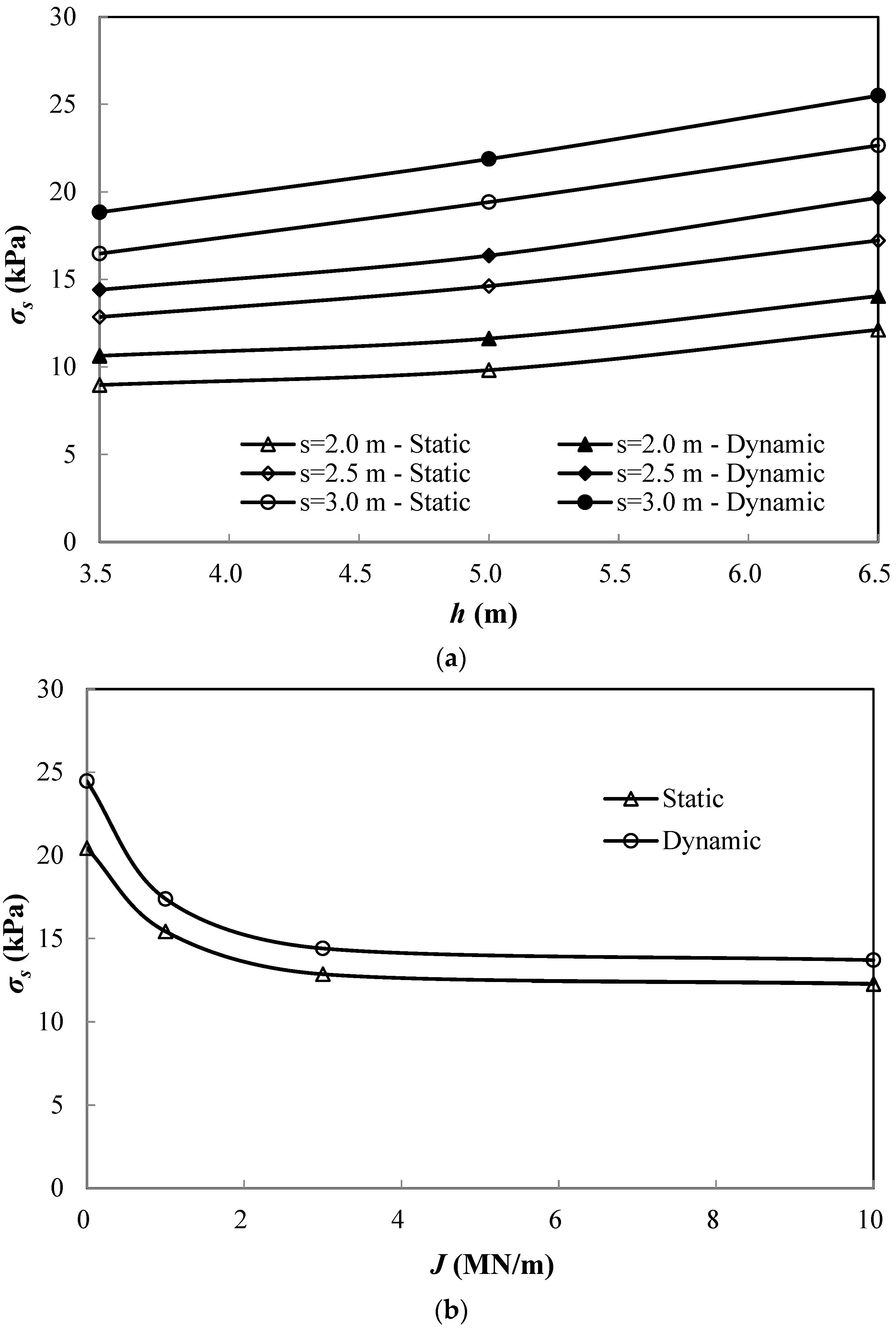
To investigate the contribution of slightly overconsolidated subsoil in the reinforced piled embankment under cyclic loads, a parametric study was performed by changing the geometry (embankment height and pile spacing), embankment properties, geogrid stiffness, and the velocity of cyclic loads. It should be noted that the model with (s = 2.5 m, h = 3.5 m, J = 3.0 MN/m, v = 60 km/h; Cc = 0.3) is assumed as the standard model. The results are presented in terms of the vertical stress carried by the subsoil in Figure 5. As anticipated, the general trend of vertical stress carried by the subsoil under cyclic loads showed excellent correspondence with that under a static load. Most notably, the cyclic loads suggested that the vertical stress carried by the subsoil was between 8–41% larger than the static load.
Figure 5a shows that the vertical stress carried by the slightly overconsolidated subsoil increases as the pile spacing and embankment height become larger. The enlargement in pile spacing from 2.0 to 3.0 m caused the vertical stress carried by the subsoil to increase by approximately 88%, whereas the vertical stress increased by 37% when increasing the embankment height from 3.5 to 6.5 m. This demonstrates that the ground reaction of lightly overconsolidated subsoil is more sensitive to the pile spacing than embankment height under cyclic loads.
The inclusion of a geogrid improves the load transfer from embankments to piles, resulting in an increase in the arching effect, and it is of importance in enhancing the performance of reinforced piled embankments. As anticipated, the vertical stress carried by the slightly overconsolidated subsoil with a geogrid stiffness of 3 MN/m was much lower (approximately 41% lower) compared with the unreinforced case (J = 0 MN/m) under cyclic loads. We also observed that there exists a critical value of the geogrid stiffness (i.e., 3 MN/m herein), below which the vertical stress carried by the subsoil decreases significantly, while the influence becomes less important when the stiffness exceeds this threshold value.
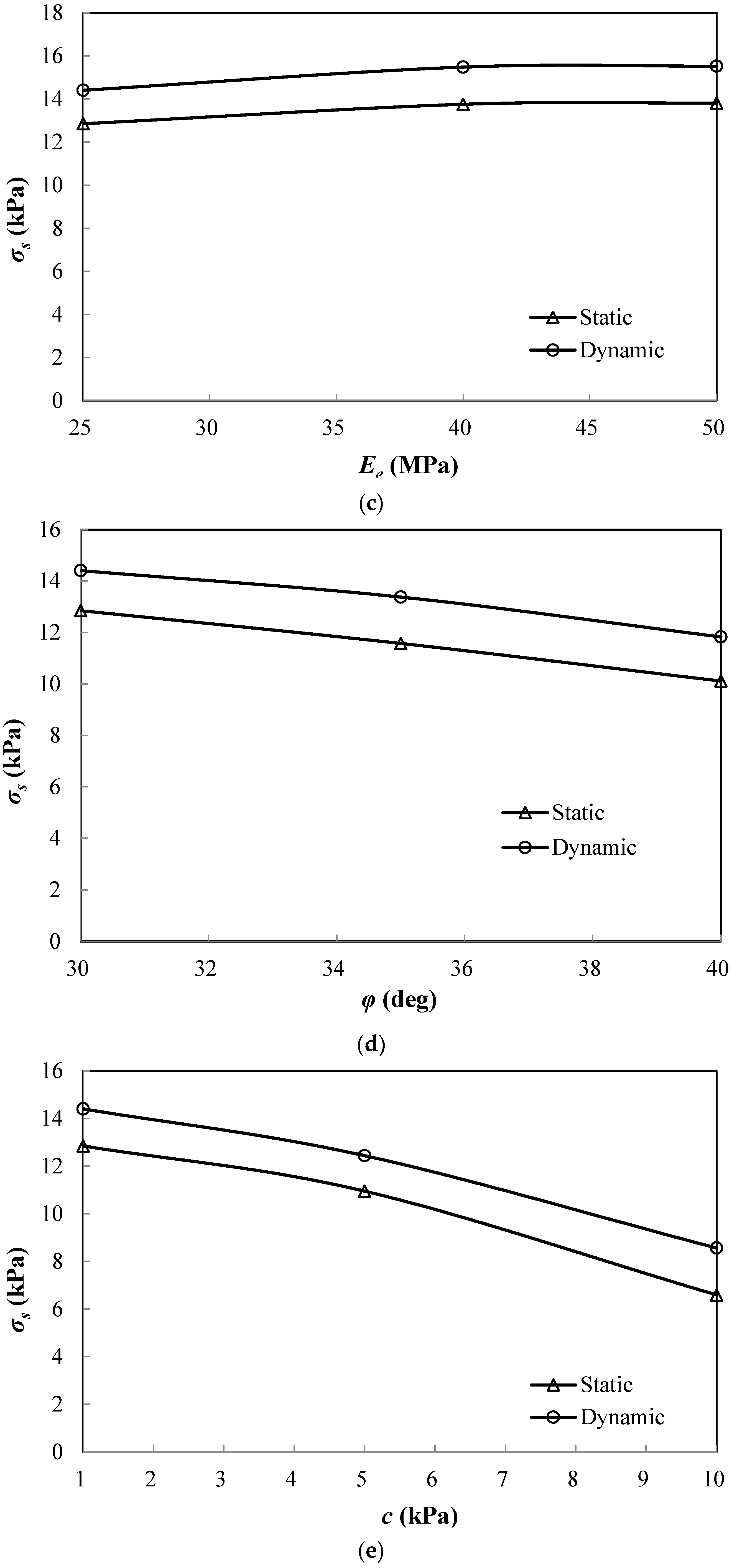
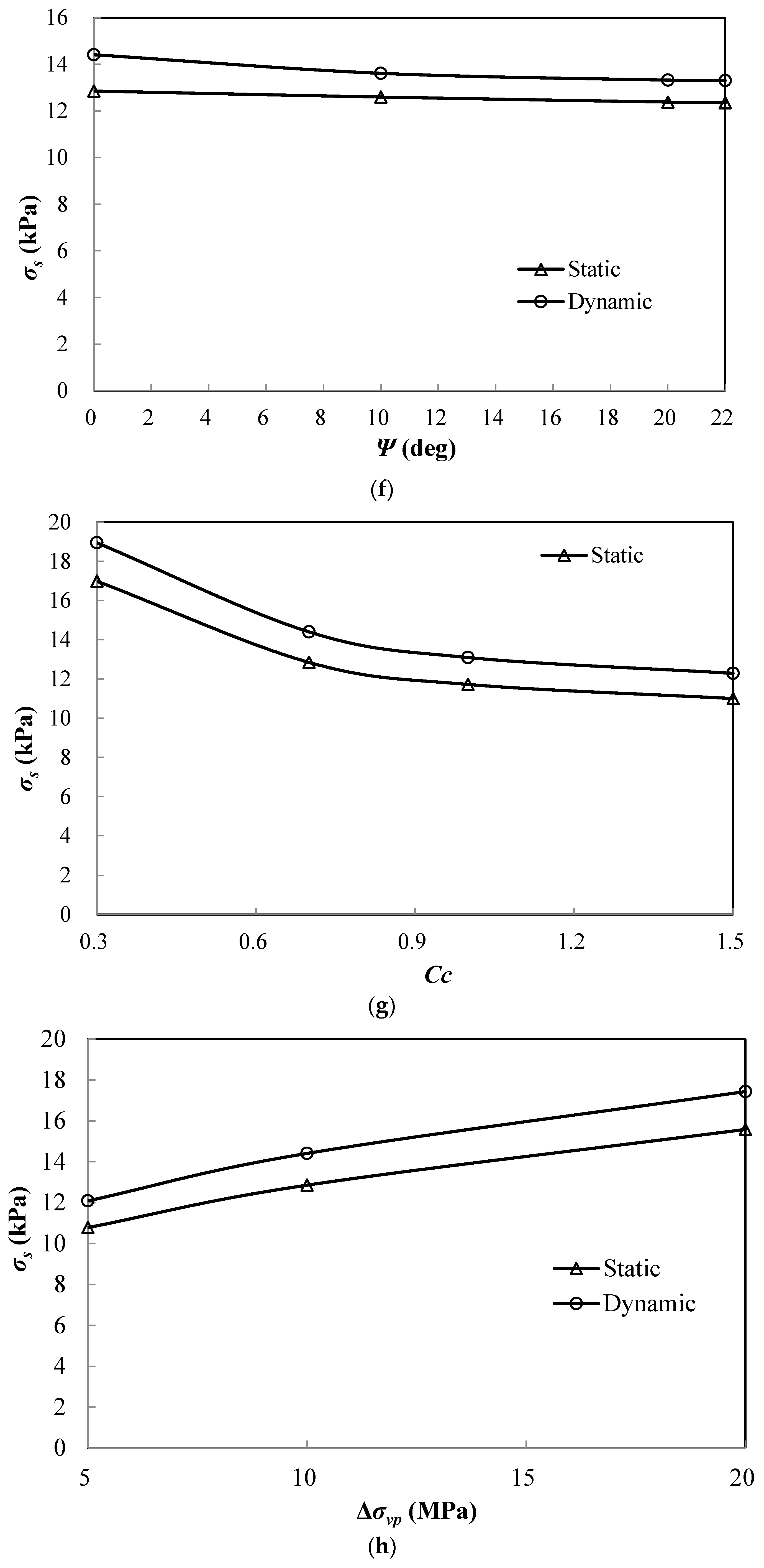
As shown in Figure 5c–f, the vertical stress carried by the slightly overconsolidated subsoil decreases when increasing the friction angle, dilation angle, and cohesion strength of the embankment material, whereas only slightly changes were denoted when increasing the elastic modulus. The cohesion strength, as expected, was found to be the most sensitive factor among all the properties of the embankment considered herein; as a result, an increases in cohesion from 1 to 10 kPa under cyclic loads caused the subsoil stress to decrease by approximately 40%.
Figure 5g,h indicates how the vertical stress was influenced by the compression index (Cc) and preconsolidation stress of lightly overconsolidated subsoil. It is clearly shown that the increase in Cc from 0.3 to 0.7 considerably decreased the vertical stress by approximately 24% both for the static and dynamic situations. However, further increasing the value of Cc led to a small growth in the vertical stress (less than 10%). As anticipated, the increase in the preconsolidation stress reduced the compressibility of the subsoil and therefore led to a rise in the vertical stress of approximately 16% when redoubling the preconsolidation stress.
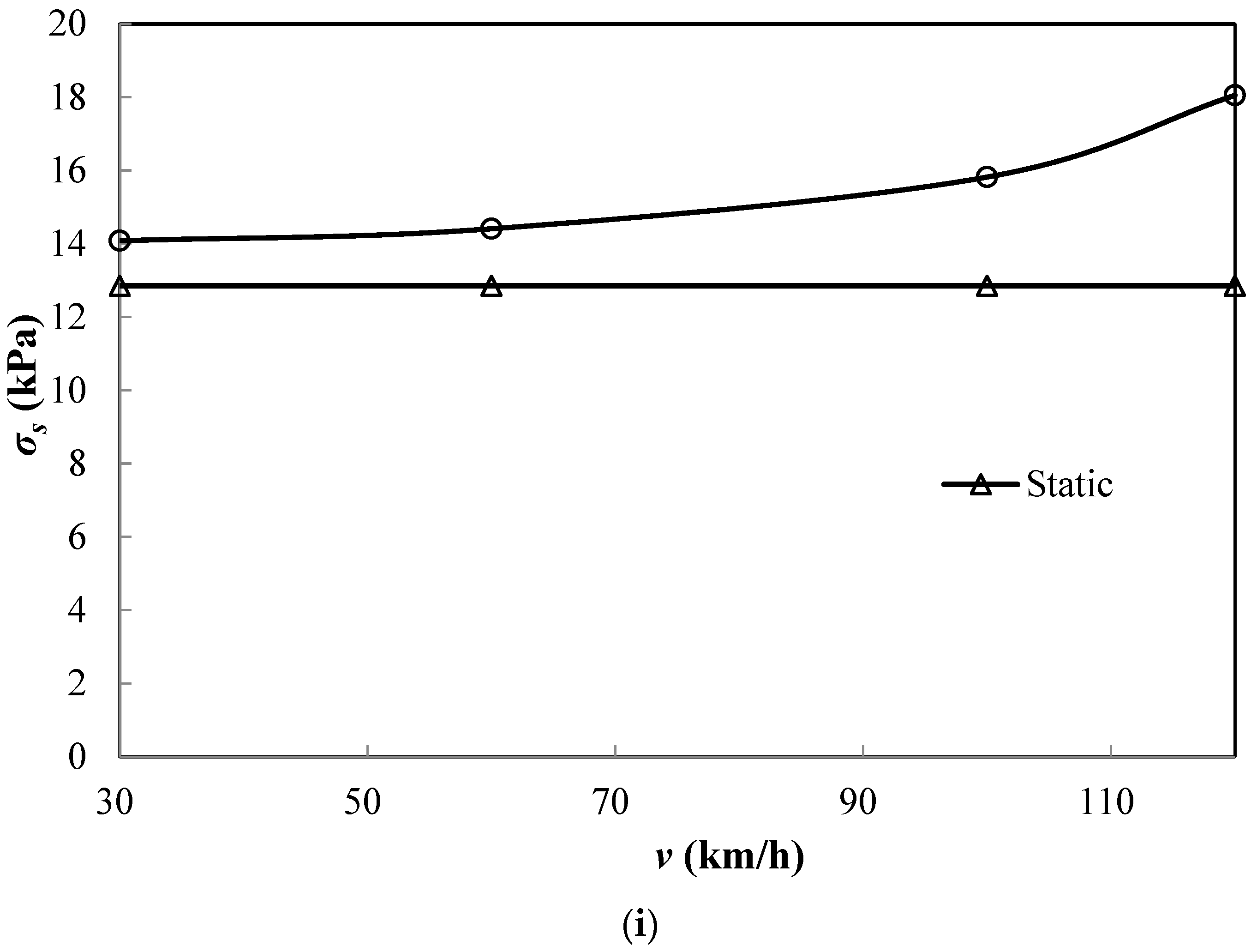
The influence of the velocity of the cyclic loads on the vertical stress carried by the slightly overconsolidated subsoil was investigated, and the results are shown in Figure 5i. The increased velocity of the cyclic loads caused the vertical stress carried by the subsoil to increase, especially for the relatively high velocities. As a result, the stress carried by the subsoil slightly increased by 2% with the increase in velocity from 30 to 60 km/h; however, the stress considerably increased by nearly 25% with the change in velocity from 60 to 120 km/h.

5. Comparison of the FEM with Modified Analytical Method

5.1. Modified Analytical Method

As presented by Zhuang and Wang [52], the geogrid and subsoil act together to support the base of an arching embankment, deriving the following equation:
14.8 a s + a J s a y s a 3 + σ s σ e = 0
where σs is vertical stress carried by subsoil; σe is vertical stress at the base of the arching embankment; and the vertical stress when arching fails either at the crown or the pile cap under cyclic loads can be calculated based on the Boussinesq equation.
For the lightly overconsolidated clay subsoil layer, the ‘elastic’ subsoil response (limited by the preconsolidation stress) can be written as:
σ s = k s y Δ σ v p
where y is the subsoil settlement; ks is the ‘subgrade reaction’ at the surface of the subsoil (kN/m2/m); and Δσvp is the incremental stress acting on the subsoil to reach the preconsolidation stress. For elastic reloading to the preconsolidation stress with Δσvp = 10 kN/m2 (constant with depth), this stiffness profile implies a settlement (y) of 59 mm at the surface of the clay layer. The ‘subgrade reaction’ of the subsoil is hence ks = (Δσvp/y) = 10/0.059 = 170 kN/m2/m.

5.2. Comparison of FEM with Modified Analytical Method

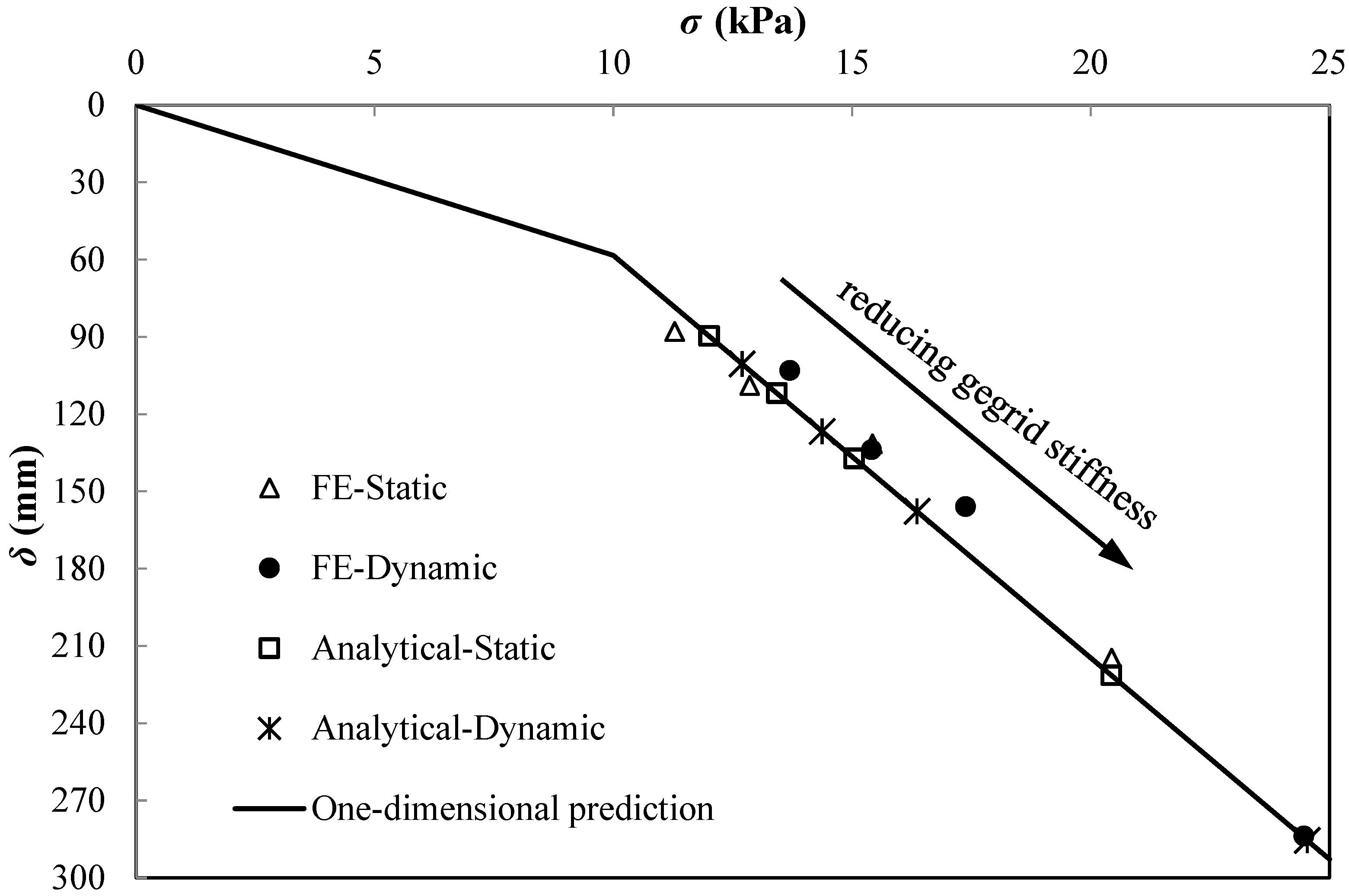
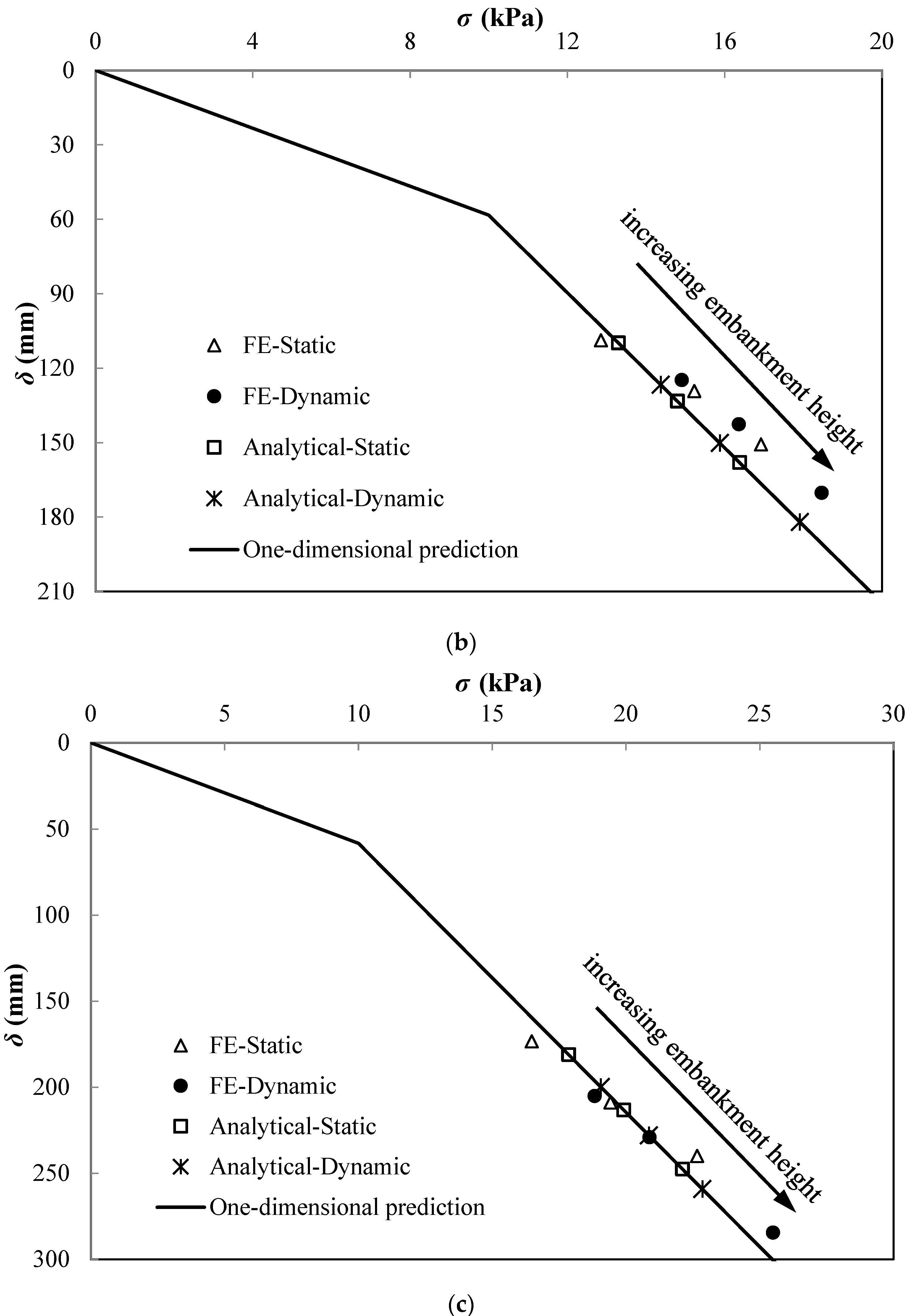
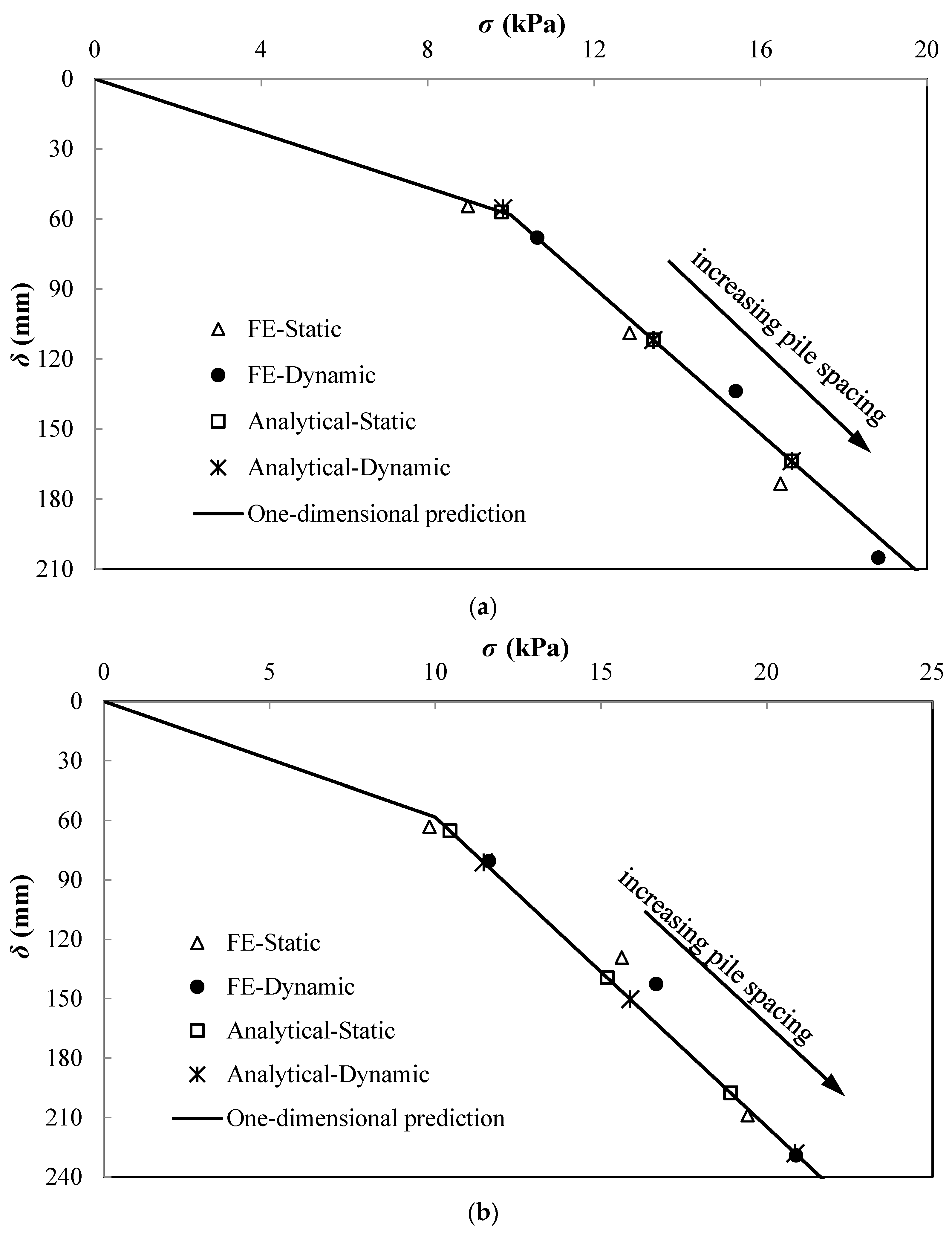
The FEM results are presented for comparison with the numerical predictions using the theoretical method presented by Zhuang and Wang [52], as shown in Figure 6, Figure 7 and Figure 8. Therein, both the results under static and cyclic loads are included. By solving Equation (4), the maximum sag of the reinforcement and settlement of the subsoil y can be calculated, and the vertical stress carried by subsoil σs can be obtained by substituting y into Equation (5). As anticipated, the predictions of the settlement δ and vertical stress σs were in the line of one-dimensional prediction (i.e., the σs line).
As shown in Figure 6, the stress carried by the lightly overconsolidated subsoil and corresponding maximum settlement decreases with the rise in geogrid stiffness. The predictions from the theoretical methods show good agreement with the FEM predictions, particularly for relatively low geogrid stiffness. The σs lines are found to slightly underestimate the vertical stress carried by the subsoil under cyclic loads.
Figure 7 and Figure 8 illustrate the effect of pile spacing and embankment height on the vertical stress and corresponding maximum settlement. The predicted ground reaction of the lightly overconsolidated subsoil (i.e., σs lines) shows good agreement with the FEM, while it slightly underestimates the vertical stress carried by the subsoil under cyclic loads for a relatively high embankment with pile spacing of less than 3.0 m. Generally, the FE results are slightly overestimated by the analytical predictions under static loads, whereas they are underestimated by those under cyclic loading, especially for a relatively high embankment and large pile spacing.

6. Conclusions

The ground reaction of lightly overconsolidated subsoil in a reinforced piled embankment under cyclic loads is presented in this paper, taking the subsoil consolidation into account. Several FE models for reinforced piled embankments were developed, by which the profiles of the settlement and vertical stress increment of the subsoil were comprehensively analyzed. The ground reactions of the subsoil from the FE results were also compared with the 1-D predictions based on the pre-yield ‘elastic’ stiffness of the subsoil, and they were found to be in excellent agreement, especially for the results at the mid-depth (z = 3 m) of the subsoil. Moreover, we also found that the ground reaction of the subsoil under cyclic loads exhibited approximately the same trend as that under static loads, while it yielded a settlement that was 23% larger than in the static situation.
The parametric study showed that the general trend of vertical stress carried by the subsoil under cyclic loads exhibited excellent correspondence with that under static loads, and the cyclic loads induced a vertical stress that was approximately 8–41% larger than in the case of the static load. The stress carried by the subsoil was found to rise with the increase in embankment height, pile spacing and preconsolidation stress of the subsoil, and the velocity of cyclic loads. The effective stress decreased with increases in geogrid stiffness, the compression index of the subsoil, and the strength parameters of the embankment. We also observed that pile spacing was the most sensitive factor that influenced the ground reaction of the lightly overconsolidated subsoil among all the parameters considered in this paper. As a result, the enlargement of the pile spacing from 2.0 to 3.0 m caused the vertical stress carried by the subsoil to increase by approximately 88%.
Finally, the ground reaction of the lightly overconsolidated subsoil under cyclic loads was incorporated into the modified analytical method of Zhuang and Wang (2018) [52], and this showed reasonable agreement between the predictions from the modified theoretical method and the FE results, particularly for the situation with relatively low geogrid stiffness, a low embankment, and small pile spacing. For the piled embankment, the subsoil may play an important role in supporting the vertical loads coming from the embankment fill, particularly under cyclic loads. The neglect of the subsoil in the design of the piled embankment may lead to a very conservative design for the settlement control of the piled embankment, resulting in an unnecessary increase in construction costs, especially for embankments constructed over subsoil of medium and high compressibility. Due to the complexity of the reinforced piled embankment, further improvement of the numerical simulations by including the multilayered soil foundation, multilayered geogrid reinforcement, and embankment with slopes should be conducted to get insight into its actual performance.

Author Contributions

Conceptualization, methodology, supervision, Y.Z.; writing—original draft preparation, software, investigation, X.S.; writing—review and editing, validation, formal analysis, K.W. All authors have read and agreed to the published version of the manuscript.

Funding

The financial support of the National Science Fund for Excellent Young Scholars of China (51922029), Natural Science Foundation of China (52109139), National Natural Science Foundation for General Program of China (52178316), and Zhejiang Provincial Natural Science Foundation of China (LQ20E080022) is acknowledged.

Institutional Review Board Statement

Not applicable.

Informed Consent Statement

Not applicable.

Data Availability Statement

Not applicable.

Conflicts of Interest

The authors declare no conflict of interest.

Notations

a(square) pile cap size (m)
Jlong-term secant stiffness (at appropriate strain) for reinforcement (kN/m run (or MN/m))
spile center-to-center spacing (for piles on a square grid) (m)
hembankment height (m)
uwexcess pore water pressure (kPa)
Δσvpthe increment of stress to reach the preconsolidation stress in the subsoil (kN/m2)
φiinterface friction angle between pile and the subsoil (degrees)
φfriction angle (degrees)
Cccompression index of the subsoil
e0initial void ratio
Mcritical stress ratio
λslope of the virgin consolidation line
κslope of the swelling line
P0static vehicle wheel load (kN)
M0unsprung weight (N∙s2/m)
μw/r(y)road roughness function (mm)
υvelocity of the vehicles (km/h)
Lgeometric curve wavelength of the pavement (m)
tduration time of load (s)
σevertical stress at the base of the embankment (including the effect of arching) (kN/m2)
σrvertical stress carried by the reinforcement (kPa)
σsvertical stress carried by the subsoil (kPa)
ymaximum sag in reinforcement (m)
ks‘subgrade reaction’ at the surface of the subsoil (kN/m2/m)
γunit weight (kN/m3)
ccohesion (kPa)
EYoung’s modulus (MPa)
E0one-dimensional subsoil stiffness (MPa)
Ψdilation angle (degrees)
μPoisson’s ratio
kpermeability coefficient (m/d)
δsettlement of the embankment (mm)

References

  1. Han, J.; Gabr, M.A. Numerical analysis of geosynthetic-reinforced and pile-supported earth platforms over soft soil. J. Geotech. Geoenviron. Eng. 2002, 128, 44–53. [Google Scholar] [CrossRef]
  2. Liu, H.L.; Ng, C.W.; Fei, K. Performance of a geogrid-reinforced and pile-supported highway embankment over soft clay: Case study. J. Geotech. Geoenviron. Eng. 2007, 133, 1483–1493. [Google Scholar] [CrossRef]
  3. Briancon, L.; Simon, B. Performance of pile-supported embankment over soft soil: Full-scale experiment. J. Geotech. Geoenviron. Eng. 2012, 138, 551–561. [Google Scholar] [CrossRef]
  4. Liu, H.L.; Kong, G.Q.; Chu, J.; Ding, X.M. Grouted gravel column supported highway embankment over soft clay: Case study. Can. Geotech. J. 2015, 52, 1725–1733. [Google Scholar] [CrossRef]
  5. Liu, C.Y.; Shan, Y.; Wang, B.L.; Zhou, S.H.; Wang, C.D. Reinforcement load in geosynthetic-reinforced pile-supported model embankments. Geotext. Geomembr. 2022, 50, 1135–1146. [Google Scholar] [CrossRef]
  6. Jelušic, P.; Žlender, B. Optimal design of piled embankmentswith basal reinforcement. Geosynth. Int. 2018, 25, 150–163. [Google Scholar] [CrossRef]
  7. Al-Naddaf, M.; Han, J.; Xu, C.; Jawad, S.; Abdulrasool, G. Experimental investigation of soil arching mobilization and degradation under localized surface loading. J. Geotech. Geoenviron. Eng. 2019, 145, 04019114. [Google Scholar] [CrossRef]
  8. Van Eekelen, S.J.M.; Han, J. Geosynthetic-reinforced pile-supported embankments: State of the art. Geosynth. Int. 2020, 27, 112–141. [Google Scholar] [CrossRef]
  9. Ghosh, B.; Fatahi, B.; Khabbaz, H.; Nguyen, H.H.; Kelly, R. Field study and numerical modelling for a road embankment built on soft soil improved with concrete injected columns and geosynthetics reinforced platform. Geotext. Geomembr. 2021, 49, 804–824. [Google Scholar] [CrossRef]
  10. Pham, T.A.; Dias, D. Comparison and evaluation of analytical models for the design of geosynthetic-reinforced and pile-supported embankments. Geotext. Geomembr. 2021, 49, 528–549. [Google Scholar] [CrossRef]
  11. van Eekelen, S.J.M.; Bezuijen, A.; van Tol, A.F. An analytical model for arching in piledembankments. Geotext. Geomembr. 2013, 39, 78–102. [Google Scholar] [CrossRef]
  12. van Eekelen, S.J.M.; Bezuijen, A.; van Tol, A.F. Validation ofanalytical models for the design of basal reinforced piled embankments. Geotext. Geomembr. 2015, 43, 56–81. [Google Scholar] [CrossRef] [Green Version]
  13. Fagundes, D.F.; Almeida, M.S.S.; Thorel, L.; Blanc, M. Loadtransfer mechanism and deformation of reinforced piled embankments. Geotext. Geomembr. 2017, 45, 1–10. [Google Scholar] [CrossRef]
  14. King, D.J.; Bouazza, A.; Gniel, J.R.; Rowe, R.K.; Bui, H.H. Serviceability design for geosynthetic reinforced columnsupported embankments. Geotext. Geomembr. 2017, 45, 261–279. [Google Scholar] [CrossRef]
  15. Feng, S.J.; Ai, S.G.; Chen, H.X. Membrane effect of geosynthetic reinforcement subjected to localized sinkholes. Can. Geotech. J. 2018, 55, 1334–1348. [Google Scholar] [CrossRef] [Green Version]
  16. Chalak, C.; Briancon, L.; Villard, P. Coupled numerical and experimental analyses of load transfer mechanismsin granular-reinforced platform overlying cavities. Geotext. Geomembr. 2019, 47, 587–597. [Google Scholar] [CrossRef]
  17. Pham, T.A. Analysis of geosynthetic-reinforced pile-supported embankment with soil-structure interaction models. Comput. Geotech. 2020, 121, 103438. [Google Scholar] [CrossRef]
  18. Zhang, C.F.; Zhao, M.H.; Zhao, H.; Zhou, S. Simplified Model of Column-Supported Embankment to Account for Nonuniform Deformations of Soils. J. Eng. Mech. 2020, 146, 4020060. [Google Scholar] [CrossRef]
  19. Rui, R.; Ye, Y.Q.; Han, J.; Zhai, Y.X.; Wan, Y.; Chen, C.; Zhang, L. Two-dimensional soil arching evolution in geosynthetic-reinforced pile-supported embankments over voids. Geotext. Geomembr. 2022, 50, 82–98. [Google Scholar] [CrossRef]
  20. Terzaghi, K. Theoretical Soil Mechanics; Wiley: New York, NY, USA, 1943. [Google Scholar]
  21. Hewlett, W.J.; Randolph, M.F. Analysis of piled embankments. Ground Eng. 1988, 21, 12–18. [Google Scholar]
  22. Zhuang, Y.; Ellis, E.A. Finite-element analysis of a piledembankment with reinforcement compared with BS 8006 predictions. Géotechnique 2014, 64, 910–917. [Google Scholar] [CrossRef]
  23. Zhuang, Y.; Wang, K.Y. Analytical Solution for Reinforced Piled Embankments on Elastoplastic Consolidated Soil. Int. J. Geomech. 2017, 17, 04016011. [Google Scholar] [CrossRef]
  24. Lai, H.J.; Zheng, J.J.; Zhang, R.J.; Cui, M.J. Classification and characteristics of soil arching structures in pile-supported embankments. Comput. Geotech. 2018, 98, 153–171. [Google Scholar] [CrossRef]
  25. Rui, R.; Han, J.; van Eekelen, S.J.M.; Wan, Y. Experimental investigation of soil-arching development in unreinforced and geosynthetic-reinforcedpile-supported embankments. J. Geotech. Geoenviron. Eng. 2019, 145, 04018103. [Google Scholar] [CrossRef]
  26. Tran, Q.A.; Villard, P.; Dias, D. Discrete and continuum numerical modeling of soil arching between piles. Int. J. Geomech. 2019, 19, 04018195. [Google Scholar] [CrossRef] [Green Version]
  27. Lai, H.J.; Zheng, J.J.; Cui, M.J.; Chu, J. “soil arching” for piled embankments: Insights from stress redistribution behaviour of DEM modelling. Acta Geotech. 2020, 15, 2117–2136. [Google Scholar] [CrossRef]
  28. Meena, N.K.; Nimbalkar, S.; Fatahi, B.; Yang, G. Effects of soil arching on behavior of pile-supported railway embankment: 2D FEM approach. Comput. Geotech. 2020, 123, 103601. [Google Scholar] [CrossRef]
  29. Lv, W.H.; Wu, T.; Gu, F.; Gao, L. Evaluation of soil arching effect due to partially mobilized shear stress in piled and geosynthetic-reinforced embankment. J. Cent. South Univ. 2020, 27, 2094–2112. [Google Scholar] [CrossRef]
  30. Wang, K.; Cao, J.; Wang, X.; Ning, Y. Soil Arching of Piled Embankment in Equal Settlement Pattern: A Discrete Element Analysis. Symmetry 2021, 13, 1627. [Google Scholar] [CrossRef]
  31. BS8006; Code of Practice for Strengthened/Reinforced Soils and Other Fills, vol. 1. British Standards Institution: London, UK, 2010.
  32. EBGEO. Recommendations for Design and Analysis of Earth Structures Using Geosynthetic Reinforcements; EBGEO: San Ramon, CA, USA, 2011; ISBN 978-3-433-02983-1. [Google Scholar]
  33. Zhuang, Y.; Wang, K.Y.; Liu, H.L. A simplified model to analyse the reinforced piledembankments. Geotext. Geomembr. 2014, 42, 154–165. [Google Scholar] [CrossRef]
  34. Zhuang, Y.; Wang, K.Y. Three-dimensional behavior of biaxial geogrid in a piled embankment: Numerical investigation. Can. Geotech. J. 2015, 52, 1629–1635. [Google Scholar] [CrossRef]
  35. Zhuang, Y.; Ellis, E.A. Finite-element analysis of a piled embankment with reinforcement and subsoil. Géotechnique 2016, 66, 596–601. [Google Scholar] [CrossRef] [Green Version]
  36. Wang, H.L.; Chen, R.P.; Liu, Q.W.; Kang, X. Investigation on geogrid reinforcement and pile efficacy in geosynthetic-reinforced pile-supported track-bed. Geotext. Geomembr. 2019, 47, 755–766. [Google Scholar] [CrossRef]
  37. Zhao, L.S.; Zhou, W.H.; Geng, X.; Yuen, K.V.; Fatahi, B. A closed-form solution for column-supported embankments with geosynthetic reinforcement. Geotext Geomembr 2019, 47, 389–401. [Google Scholar] [CrossRef] [Green Version]
  38. Xu, C.; Liang, C.; Shen, P.P.; Chai, F. Experimental and numerical studies on the reinforcing mechanisms of geosynthetic-reinforced granular soil under a plane strain condition. Soils Found. 2020, 60, 466–477. [Google Scholar] [CrossRef]
  39. Zhuang, Y.; Cheng, X.T.; Wang, K.Y. Analytical solution for geogrid-reinforced piled embankments under traffic loads. Geosynth. Int. 2020, 27, 249–260. [Google Scholar] [CrossRef]
  40. Zhang, J.; Jia, Y.; Zheng, Y.; Miao, C. DEM Simulation of the Load Transfer Mechanism of a GRPS Embankment with a Fixed Geogrid Technique. Appl. Sci. 2021, 11, 8814. [Google Scholar] [CrossRef]
  41. Hu, S.; Zhuang, Y.; Zhang, X.; Dong, X. A Design Chart for the Analysis of the Maximum Strain of Reinforcement in GRPEs Considering the Arching and Stress History of the Subsoil. Appl. Sci. 2022, 12, 2536. [Google Scholar] [CrossRef]
  42. Heitz, C.; Lüking, J.; Kempfert, H.G. Geosynthetic reinforced and pile supported embankments under static and cyclic loading. In Proceedings of the 4th European Geosynthetics Conference, EuroGeo 4, Edinburgh, UK, 7–10 September 2008; International Geosynthetics Society (CD-ROM): Jupiter, FL, USA, 2008. [Google Scholar]
  43. Han, J.; Bhandari, A. Evaluation of geogrid-reinforced pile-supported embankments under cyclic loading using discrete element method. US-China Workshop Ground Improv. Technol. 2009, 188, 73–82. [Google Scholar]
  44. Thach, P.N.; Liu, H.L.; Kong, G.Q. Evaluation of PCC pile method in mitigating embankment vibrations from a high-speed train. J. Geotech. Geoenviron. Eng. 2013, 139, 2225–2228. [Google Scholar] [CrossRef]
  45. Han, G.X.; Gong, Q.M.; Zhou, S.H. Soil arching in a piled embankment under dynamic load. Int. J. Geomech. 2015, 15, 04014094. [Google Scholar] [CrossRef]
  46. Zhai, W.; Wei, K.; Song, X.; Shao, M. Experimental investigation into ground vibrations induced by very high speed trains on a non-ballasted track. Soil Dyn. Earthq. Eng. 2015, 72, 24–36. [Google Scholar] [CrossRef]
  47. Chen, R.P.; Wang, Y.W.; Ye, X.W.; Bian, X.C.; Dong, X.P. Tensile force of geogrids embedded in pile-supported reinforced embankment: A full-scale experimental study. Geotext. Geomembr. 2016, 44, 157–169. [Google Scholar] [CrossRef]
  48. Messioud, S.; Okyay, U.S.; Sbartai, B.; Dias, D. Dynamic response of pile reinforced soils and piled foundations. Geotech. Geol. Eng. 2016, 34, 789–805. [Google Scholar] [CrossRef]
  49. Pham, H.V.; Dias, D. 3D numerical modeling of a piled embankment under cyclic loading. Int. J. Geomech. 2019, 19, 04019010. [Google Scholar] [CrossRef]
  50. Wang, H.L.; Chen, R.P. Estimating static and dynamic stresses in geosynthetic-reinforced pile-supported track-bed under train moving loads. J. Geotech. Geoenviron. Eng. 2019, 145, 04019029. [Google Scholar] [CrossRef]
  51. Wang, K.Y.; Zhuang, Y.; Liu, H.L.; Miao, Y. Soil arching in highway piled embankments subjected to moving shakedown limit loads. Eur. J. Environ. Civ. Eng. 2020, 24, 1120–1134. [Google Scholar] [CrossRef]
  52. Zhuang, Y.; Wang, K.Y. Finite-element analysis of arching in highway piled embankments subjected to moving vehicle loads. Geotechnique 2018, 68, 857–868. [Google Scholar] [CrossRef]
  53. Navas, P.; Yu, R.C.; López-Querol, S.; Li, B. Dynamic consolidation problems in saturated soils solved through u–w, formulation in a LME meshfree framework. Comput. Geotech. 2016, 79, 55–72. [Google Scholar] [CrossRef] [Green Version]
  54. Potyondy, J.G. Skin friction between various soils and construction materials. Geotechnique 1961, 11, 339–353. [Google Scholar] [CrossRef]
  55. Huang, Y.H. Pavement Analysis and Design; Prentice Hall: Englewood Cliffs, NJ, USA, 1993. [Google Scholar]
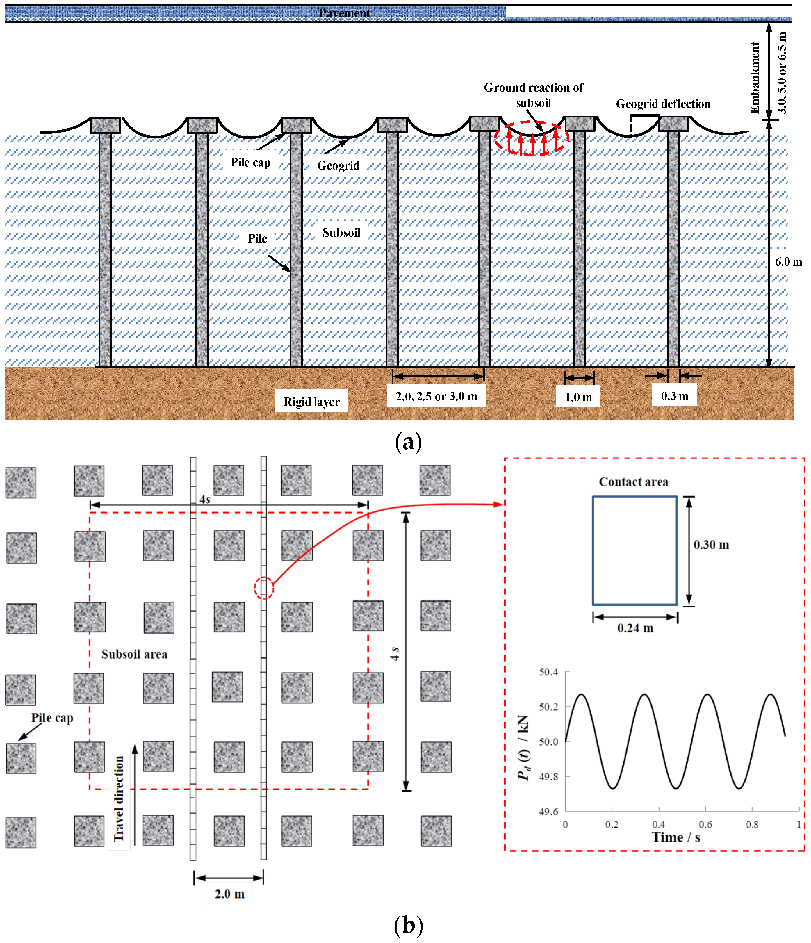
Figure 1. Cross-section of the reinforced piled embankment with load-moving strip of cyclic loading: (a) cross-section of a reinforced piled embankment; (b) load-moving strip and pile arrangement.
Sustainability 15 00619 g001
Figure 2. This is a figure. Schemes follow the same formatting.
Sustainability 15 00619 g002
Figure 3. Profiles of vertical stress increment and settlement with depth of subsoil (s = 2.5 m, h = 3.5 m): (a) increment in vertical stress; (b) settlement.
Sustainability 15 00619 g003aSustainability 15 00619 g003b
Figure 4. Settlement and stress increment for subsoil at the center of a diagonal span (s = 2.5 m, h = 3.5 m): (a) surface of subsoil (z = 0 m); (b) mid-depth of subsoil (z = 3 m).
Sustainability 15 00619 g004
Figure 5. Variation in vertical stress acting on the surface of the soil (σs) with influence factors: (a) effect of embankment height and pile spacing; (b) effect of geogrid stiffness; (c) effect of elastic modulus of embankment; (d) effect of friction angle of embankment; (e) effect of cohesion of embankment; (f) effect of dilation angle of embankment; (g) effect of compression index of lightly overconsolidated subsoil; (h) effect of preconsolidation stress of lightly overconsolidated subsoil; and (i) effect of velocity of cyclic loads.
Sustainability 15 00619 g005aSustainability 15 00619 g005bSustainability 15 00619 g005cSustainability 15 00619 g005d
Figure 6. Comparison of FE results with predictions for different geogrid stiffness values (s = 2.5 m, h = 3.5 m).
Sustainability 15 00619 g006
Figure 7. Comparison of FE results with predictions for different pile spacing values: (a) s = 2.0 m; (b) s = 2.5 m; and (c) s = 3.5 m.
Sustainability 15 00619 g007aSustainability 15 00619 g007b
Figure 8. Comparison of FE results and predictions with different embankment heights: (a) h = 3.5 m; (b) h = 5.0; and (c) h = 6.5.
Sustainability 15 00619 g008aSustainability 15 00619 g008b
Table 1. Summary of the material parameters used in the finite element analyses.
h
(m)
γ
(kN/m3)
c
(kPa)
φ
(Degree)
E
(MPa)
Ψ
(Degree)
μCcMe0
AC layer0.1521.0--4000-0.25---
Base0.2020.0--1000-0.25---
Subbase0.2518.0--500-0.25---
Embankment3.5, 5.0 or 6.517.01, 5 or 1030, 35 or 4025, 40 or 500, 10, 20 or 220.20---
Pile6.0023.5--20,000-0.20---
Subsoil6.0017.0-26--0.300.3, 0.7, 1.0 or 1.51.031.79
GeogridTensile stiffness J = 0, 1, 3 or 10 MN/m, v = 0
Note: h = embankment height; γ = unit weight; c’ = cohesion; φ’ = friction angle; E = Young’s modulus; Ψ = dilation angle; J = stiffness of the geogrid; μ = Poisson’s ratio; M = critical stress ratio; e0 = initial void ratio.
Disclaimer/Publisher’s Note: The statements, opinions and data contained in all publications are solely those of the individual author(s) and contributor(s) and not of MDPI and/or the editor(s). MDPI and/or the editor(s) disclaim responsibility for any injury to people or property resulting from any ideas, methods, instructions or products referred to in the content.