Article

In Vitro Corrosion Resistance of a Layer-by-Layer Engineered Hybrid Coating on ZK60 Magnesium Alloy

by
Mostafizur Rahman
1,2,
Rajkamal Balu
1,
Naba Kumar Dutta
1,* and
Namita Roy Choudhury
1,*
1
School of Engineering, RMIT University, Melbourne, VIC 3000, Australia
2
Department of Mechanical Engineering, Dhaka University of Engineering & Technology, Gazipur 1707, Bangladesh
*
Authors to whom correspondence should be addressed.
Sustainability 2022, 14(4), 2459; https://doi.org/10.3390/su14042459
Submission received: 11 January 2022 / Revised: 17 February 2022 / Accepted: 18 February 2022 / Published: 21 February 2022
(This article belongs to the Special Issue Toward Sustainable Multifunctional Coatings)

Abstract

:
Magnesium alloys are next generation biodegradable implants for clinical applications. However, their medical applications are currently hampered by their rapid corrosion rate in the physiological environment. To overcome such limitations, we have applied a novel layer-by-layer engineering approach of introducing anodization-induced microrough oxidized surface on ZK60 magnesium alloy, followed by surface mineralization with natural calcium apatite (hydroxyapatite, HA), and surface coating with natural protein (silk fibroin, SF); which, effectively reduces corrosion and degradation rate of ZK60 in simulated body fluid. Anodization of ZK60 improved the surface adhesion strength of HA layer; HA layer increased the surface roughness, hydrophilicity and micro-hardness, whereas decreased ionic release; SF layer decreased surface microroughness and hydrophilicity, whereas improved the stability of HA layer. The SF + HA coating on anodized ZK60 effectively decreased the in vitro weight loss (degradation) by almost six times, whereas corrosion rate by more than two orders in magnitude. Such interfacial coatings, with biocompatible SF on the outer surface, could potentially expand the application of ZK60 in the field of biomedical engineering.

1. Introduction

Metallic constructs made of stainless steel, titanium, cobalt-chrome and nickel-titanium alloys have been conventionally used as bone implants. However, in the long run, they cause distress to the host body due to release of toxic metal ions, mechanical property mismatch, and non-biodegradability leading to secondary surgical procedures [1]. In recent years, magnesium (Mg) and its alloys have emerged as a new generation biomaterial, and as an alternative to the above conventional metallic implant materials owing to their superior biocompatibility, biodegradability, density and mechanical properties close to that of human bone [2]. Moreover, Mg exists in the human body as an abundant element skeletal muscles and soft tissues (30–40%), distributed in bones (60%), and take part in the physiological activities [3]. However, the main problem associated with the use of Mg as implant material is their rapid corrosion rate in the biological environments. Corrosion of Mg generates a large amount of hydrogen gas, which deposits as gas pockets adjacent to the implants, which leads to quick loss of mechanical integrity and stability of implants hampering the tissue and mineral regeneration process [4]. Alloying and surface treatment or modifications are effective routes to improve resistance to corrosion and degradation of metallic implants [5]. Over the past two decades, several Mg-based alloys, including Mg-calcium (Ca) based, Mg-zinc (Zn) based, Mg-zirconium (Zr) based, Mg-strontium (Sr) based, Mg-copper (Cu) based and Mg-rare earth elements (RE) based alloys, have been developed and investigated for their biomedical applications [6]. Although Mg alloys exhibit improved mechanical and corrosion resistant properties (compared to pure Mg), they still suffer from moderately fast corrosion and degradation rate (in comparison with other bio-metal alloys), and relatively low cellular response (compared to ceramic and polymeric biomaterials) in biological environments, which limit their application in the field of biomedical engineering [7].
Several surface treatment techniques, including conversion coating, electrochemical plating, anodization, organic coating and plasma electrolytic oxidation coating, have been stated in the literature for improving corrosion and degradation resistance of Mg alloys [8]. The electrodeposition (anodic or cathodic) processes owing to their simplicity, cost-effectiveness and friendly environment could be an effective method to create a protective layer against corrosion, and/or vary the surface properties [9]. On the other hand, calcium (Ca) and phosphate (P) are the essential elements of the natural bone; where, Ca-P coatings, such as dicalcium phosphate dihydrate (DCPD), octacalcium phosphate (OCP), tricalcium phosphate (TCP), and hydroxyapatite (HA) could be a promising approach for improving corrosion resistance and clinical applications of Mg alloys [10,11]. Recently, we have demonstrated that a combination of electrochemical surface treatment and inorganic Ca-P coating greatly improves the corrosion and degradation resistance of Mg alloy WE43 in simulated body fluid [11]. But single layer of Ca-P coating on Mg substrates could not improve corrosion and degradation resistance in the physiological environment compared to layer by layer coatings on Mg alloys [12]. Combination with inorganic and organic polymeric material like silk fibroin (SF) offers a potential route to enhance biocompatibility and biodegradability, and promising anti-corrosive of Mg and Mg alloys [13].
ZK60 is a commercially available Mg-Zn-Zr alloy, which has been extensively used for industrial applications. It is a promising next generation biomaterial for implant applications; where, zirconium (Zr) and zinc (Zn) have been reported to play pivotal roles in bone resorption and regeneration [14,15]. Chemically deposited Ca-P coating has been reported to promote the corrosion resistance and biocompatibility of ZK60; however, the coating loses its integrity (formation of cracks) with pH and time (1 week) [16]. In comparison, electrodeposited Ca-P coating showed not only better integrity and corrosion resistance, but also flake-like Ca-P microstructures [17]. Recently, electrophoretic deposition of HA nanoparticles on surface oxidized ZK60 was reported; however, the coating loses its integrity (formation of cracks) with time (10 days) in simulated body fluid [18]. Moreover, biopolymers, such as poly(methyl methacrylate) and SF have also been reported to enhance corrosion resistance and biocompatibility; however, their protection efficiency in simulated body fluids still needs to be investigated [19,20]. In recent years, hybrid coatings comprising polymers such as polycaprolactone (PCL) and ceramics have been reported to significantly improve the corrosion resistance of Mg-based materials [12]; however, SF has not been investigated for ZK60. Adopting the mechanical, anticorrosion and biomedical properties of SF and CaP coatings on Mg alloys could be a promising hybrid coating. In this work, with an outlook to achieve not only superior corrosion and degradation resistance but also to tune or improve the surface properties of Mg-based materials, ZK60 Mg alloy was anodized to form a microrough surface followed by layer-by-layer fabrication of bioinorganic-bioorganic hybrid coating by surface mineralization and spin coating.

2. Materials and Methods

2.1. Materials

Commercially available ZK60 (94.13 wt.% Mg, 5.42 wt.% Zn, and 0.45 wt.% Zr) rods (300 mm length and 10 mm diameter) was purchased from American Elements, U.S.A. The Bombyx mori silk fibers were procured from Raxor Yarns, Australia. Calcium chloride (CaCl2), sodium hydroxide (NaOH), ammonium dihydrogen phosphate (NH4H2PO4), sodium carbonate (Na2CO3), sodium nitrate tetrahydrate (Ca(NO3)2.4H2O), hydrogen peroxide (H2O2), and ethanol were collected from Chem-Supply, Australia. Hanks’ Balanced Salt solution was procured from Sigma-Aldrich, Australia.

2.2. Preparation of Substrates

The ZK60 rods (length 300 mm and diameter 10 mm) were cut into 3 mm thickness of cylindrical discs by electrical discharge machining. The exposed surface of the discs was ground using silicon carbide (SiC) abrasive paper with different grits (400, 800, and 1200), and washed with acetone. To obtain a mirror-finish surface, the discs were polished with 3.0 µm diamond polish and alumina polish suspensions of 0.5 µm, respectively, using a materialographic grinding with multiple sample holder and polishing machine (Struers). The polished discs were cleaned with acetone for 3 min and used as substrates.

2.3. Preparation of Aqueous Silk Fibroin (SF) Solution

The SF solution was made according to the method previously reported by Jasmin et al. [20]. The collected silk fibers were cut down into small pieces and put them in 0.02 M aqueous Na2CO3 solution for 30 min for boiling purpose. The degummed silk fibers were then washed in Milli-Q water and air-dried overnight at room temperature. The silk fibers were dried out and dissolved in the solution of CaCl2/water/ethanol mixture (molar ratio of 1:8:2) at 70 °C for 3 h. The obtained SF solution was dialyzed (using a regenerated cellulose tubing) in Milli-Q water. The dialyzed SF solution was then centrifuged for 30 min at 10,000 rpm, and the supernatant was strained (using 1.2 µm syringe filter) and concentrated in the fume hood at room temperature. The final concentrated solution of SF stock was put at 8 wt.% and was put away in a refrigerator at −4 °C to prevent natural silk gelation.

2.4. Fabrication of Hybrid Coating

The hybrid coating on ZK60 Mg alloy was fabricated as given below:
(i)
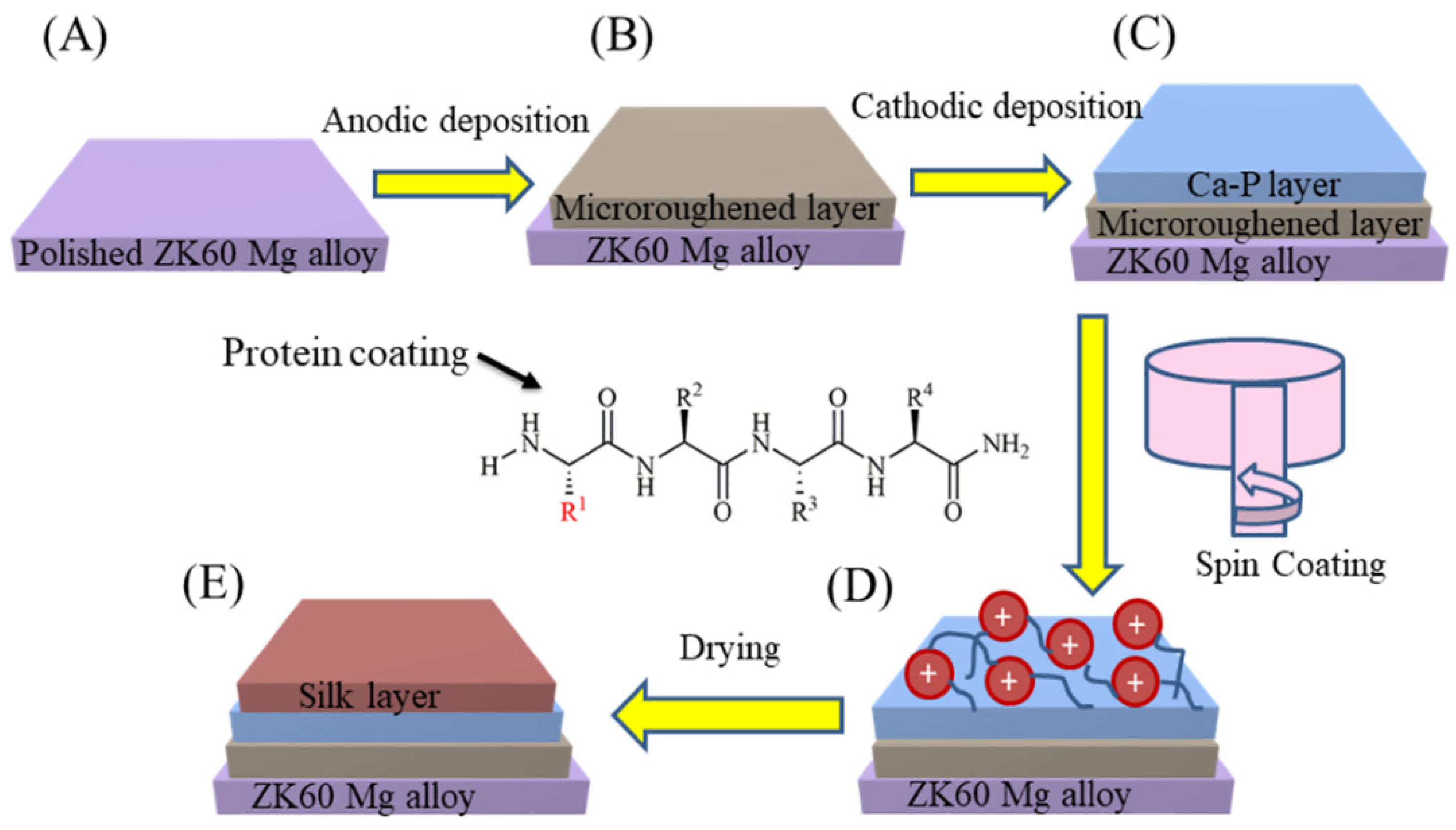
Anodization: A microrough surface with natural oxide layer was formed on the surface of bare ZK60 (substrate) using the anodic deposition process. In a typical process, the substrate was immersed into an electrolyte (1 M NaOH solution), and an electrical connection was made between the anode (substrate; +ve charged) and the cathode (platinum electrode; -ve charged). An electric potential of 5 V was applied for 1 h at room temperature for the anodic deposition, based on optimized parameters [11]. The anodized applied voltages such 3, 5, 7, and 10 V were chosen in our initial experiments. The crack-free anodized surface was obtained at 3 and 5 V and these optimized parameters were chosen in subsequent studies. After anodization, the samples were cleaned in ethanol using a sonication bath and dried using a nitrogen stream.
(ii)
Surface mineralization: The Ca-P mineral layer was created on the anodized ZK60 surface using the cathodic deposition process. The cathodic deposition was performed using an electrical connection opposite to that of the anodic deposition process, i.e., an electrical connection was made between the anode (substrate; -ve charged) and the cathode (platinum electrode; +ve charged). The electrolyte used for this process contains 6.9 g/L of NH4H2PO4, 23.6 g/L of Ca(NO3)2.4H2O, and 5 mL/L of 30 vol% of H2O2. The applied voltage for cathodic deposition was 5 V for 2 h at room temperature, based on optimized parameters [11]. After cathodization, the dicalcium phosphate dehydrate (DCPD) coating formed on the anodized ZK60 surface was rinsed with distilled water and dried out using a stream of nitrogen. The samples were then immersed in 1 M NaOH solution for 2 h at 80 °C to convert DCPD coating into the HA coating [11]. The HA coated sample was then rinsed with distilled water, dried out using a stream of nitrogen, and air-dried in an oven for 24 h at 40 °C.
(iii)
Spin coating: The SF coating on the HA coated sample was fabricated using a spin coater (Polos, USA). The amount of SF solution used for each sample was about 50 µL. The spin coating process was performed in three spinning steps: (i) 3000 rpm for 10 s, (ii) 2000 rpm for 10 s, and (iii) 1000 rpm for 10 s. About five coating cycles were employed to get a uniform and relatively thick SF coating or outer layer. The specimens were then air-dried in an oven for 24 h at 40 °C. A schematic diagram of the dual-layer hybrid coating process is shown in Figure 1.
Anodization chemical reaction
Anodic reaction
Mg     Mg 2 + + 2 e
Cathodic reaction
H 2 O     H 2 + 2 OH
Anodic film formation reaction by combining Equations (1) and (2)
Mg 2 + + 2 OH     Mg ( OH ) 2
Mineralization chemical reaction
Cathodic deposition reaction:
Ca 2 + +   HPO 4 2 +   H 2 O     CaHPO 4 2 H 2 O   ( DCPD )
HA formation reaction:
10 CaHPO 4 2 H 2 O + 12 OH Ca 10 ( PO 4 ) 6 ( OH ) 2 ( HA ) + 4 PO 4 3 + 30 H 2 O

2.5. Characterization of Morphology, Composition, Phase and Structure

The surface morphology, chemical composition, inorganic phase and protein secondary structure of bare ZK60, HA coating on anodized ZK60, and SF coating on HA layer, respectively, was characterized using scanning electron microscopy (SEM), energy dispersive X-ray spectroscopy (EDS), X-ray diffraction (XRD), and Fourier transform infrared spectroscopy (FTIR). The surface morphology and chemical composition of samples was analyzed using an FEI Quanta 200 SEM, operated with an accelerating voltage of 20 to 30 kV, and equipped with EDS. The thickness of the coatings was measured from the SEM cross-sectional images. The surface roughness of the samples was determined using a KLA-Tencor P-16+ surface profilometer. The inorganic phase of HA, and secondary structural conformation of SF was analyzed using a Bruker Discover XRD, operated with Cu Kα radiation. The measurements were made with a scanning step of 0.02°, diffraction angle (15 to 60°), and scanning speed of 2 s/step. The functional groups of HA and SF coatings was examined using a PerkinElmer Spotlight 400 FTIR equipped with an attenuated total reflection (ATR) accessory. The measurement was made using the webnumber of 700–4000 cm−1.

2.6. Analysis of Surface Mechanical Property

The surface microhardness of fabricated samples was evaluated using a Buehler hardness tester. The Vickers hardness test was performed at a force of 0.5 kgf and a dwell time of 15 s. At least three indentations were made, and the mean microhardness values were documented for each sample with standard deviations (SD). The adhesion strength of SF + HA and HA coating on anodized ZK60 was assessed according to ASTM F1044 standard [11], using an Instron 5569 universal testing machine. The applied load and crosshead velocity was 10 kN and 1 mm/min, respectively. The samples were examined in triplicates, and the mean value with SD was recorded.

2.7. Measurement of Surface Wettability

The water contact angle of bare ZK60, HA coated ZK 60, and SF + HA coated ZK60 samples was evaluated using an Dataphysics Particle and Surface Science OCA20 contact angle (CA) measurement equipment. Water droplets of about 5 µL were placed on the samples and the droplet-substrate images were captured immediately using a camera attachment. The samples were examined in triplicates, and the average value with SD was recorded.

2.8. In vitro Degradation Assessment

The weight loss profile of bare ZK60, HA coated ZK 60, and SF + HA coated ZK60 samples was evaluated by immersion in Hank’s solution, and measuring the weight loss for 21 days according to the ASTM-G31-72 [21,22]. The Hank’s solution composed of KCl (0.40 g/L), CaCl2 (0.18 g/L), NaCl (8.00 g/L), Na2PO4 (0.48 g/L), KH2PO4 (0.06 g/L), MgSO4.7H2O (0.10 g/L), NaHCO3 (0.35 g/L), and D-glucose (1 g/L). The temperature of the Hanks’ solution was 37 ± 0.5 °C that was maintained using a water bath. The variation in pH of the Hank’s solution, and sample weight loss (W) was measured (using Equation (6)) periodically. The samples were rinsed with acetone and dried with nitrogen stream. The surface microstructure of the specimens after 21 days of dipping in Hank’s solution was also characterized using SEM.
W = W 1 W 2 A
where, ‘A’ is the exposed area (cm2) of the sample, ‘W1′ and ‘W2′ are the weight (mg) of the specimens before and after the immersion test, respectively [11].

2.9. In Vitro Corrosion Study

The corrosion resistance of bare ZK60, HA coated ZK60, and SF + HA coated ZK60 samples was assessed with a standard three-electrode setup using Gamry Reference 3000 potentiostat. The potentiodynamic polarization (PDP) and electrochemical impedance spectroscopy (EIS) tests were performed using Hanks’ solution as electrolyte, fabricated samples as working electrodes, saturated silver/silver chloride (Ag/AgCl) as the reference electrode, and graphite rod as the counter electrode. The exposed area of the sample is 0.785 cm2. The PDP test was performed in the range of −300 mV to +300 mV (against Ag/AgCl) and 1 mV/s was the scan rate. The EIS test was conducted in the range of 1 × 10⁻² to 1 × 10⁵ Hz where 10 mV used as signal amplitude. The corrosion rate (CR) of the samples was calculated using Equation (7).
CR = I corr . M D . V . × 3270
where, ‘Icorr’ is the corrosion current density, ‘M’ is the atomic weight of Mg (i.e., 24.305 u), ‘D’ is the density of ZK60 (1.83 g/cm3), and ‘V’ is the valence (in this case is 2), and 3270 is a constant [11]. The obtained EIS band was fit with an equivalent circuit (EC) model using a software of Gamry EchemAnalyst. The protection efficiency (PE) of SF + HA and HA coatings on ZK60 samples was determined using Equation (8).
PE = 1 I ( corr ) c I ( corr ) uc
where, ‘I(corr)c’ and ‘I(corr)uc’ are denoted as the corrosion current density of the coated and uncoated substrate, respectively [23].

3. Results and Discussion

3.1. Surface Morphology, Composition, Phase and Structure of Coatings

Figure 2A–D show the SEM images of bare, anodized, HA coated, and SF + HA coated ZK60 Mg alloy sample surface, respectively. The SEM micrograph of the bare ZK60 sample shows a uniform and smooth surface, as expected for a polished surface. Compared to the anodized surface of ZK60 is uneven because of the development of microrough surface. Such a surface increases the surface wettability in comparison with smooth surface. On the other hand, different types of HA crystal morphologies, such as flower-like, plate-like, and needle-like have been reported to be observed in Mg alloy surface [11]. The HA coating on the anodized ZK60 sample was observed to exhibit plate-like structures, which mimic the structure of natural bone tissue, and is considered to be advantageous for improving osseointegration [24]. Moreover, the HA coating on ZK60 was observed to be compact and crack-free; whereas, a relatively smooth and uniform surface was observed for SF + HA coating on ZK60. The thickness of the HA coating and SF + HA coating was measured as 7.57 ± 0.28 and 13.85 ± 0.42 μm, respectively, from the cross-sectional SEM image of SF + HA coated ZK60 sample. The elemental composition results from the respective SEM images are given in Table 1. The EDS results confirm the presence of the oxygen (O), calcium (Ca), and phosphorous (P) elements in the inorganic HA layer; where, an obtained Ca/P ratio of 1.67 confirms the Ca-P phase formed to be apatite [25]. The carbon (C) and nitrogen (N) elements measured from the SF + HA coating on ZK60 comes from the amide group of SF protein. Figure 2E–H shows the two-dimensional images of the surface roughness measured on bare, anodized, HA and SF + HA coated ZK60 Mg alloy specimens, respectively. An average surface roughness (Ra) value of 67.26 ± 1.80 nm was measured for bare ZK60, which increased to 1689.79 ± 72.35 nm after anodization resulting in the fabrication of micro roughened surface. In addition, the Ra value increased to 5410.34 ± 225.40 nm for HA coated ZK60 (which exhibited plate-like crystal structure on the coating), whereas decreased to 2189.79 ± 103.85 nm with subsequent SF coating. The increased surface roughness of anodized ZK60 is of great significance in improving the bond performance of HA coating, which enhances the durability and efficiency of corrosion resistance [2]. The observed surface roughness trend is in good agreement with features observed in SEM images. The surface roughness of the SF + HA coating on ZK60 may influence its cell interaction properties; where, cells prefer relatively rough surfaces for cellular interaction compared to smooth surfaces [26].
Figure 3 shows the XRD spectrums of bare, anodized, HA coated, and SF + HA coated ZK60 Mg alloy samples. The observed XRD peaks at 2θ values 31.9, 33.6 and 36.3 degree corresponds to Mg, which is in good agreement with values reported in the literature for ZK60 [27]. The XRD peaks observed at 2θ values 17.68, 23.91, 37.98 and 43.45 correspond to the Mg(OH)2, whereas 48.55 and 58.48 correspond to MgO, respectively. Mg(OH)2 and MgO films are stable layers that can resist the fluid permeation in the surface resulting in improved corrosion and degradation resistance [9]. On the other hand, the XRD peaks observed at 2θ values of 17.5, 38.1, 49.2 and 51.9 degree for HA coated ZK60 sample correspond to the Miller indices (110), (212), (213) and (402) of the inorganic HA phase [11]. Moreover, the (211) plane of both ZK60 and HA overlap/co-incident at 2θ value 31.9 degree [11]. The crystalline HA coating with robust binding force could reduce the corrosion and degradation rate of ZK60, and also improve the surface mechanical properties of ZK60, further extending its stability as an implant material [28,29]. The additional XRD peaks observed at 2θ values 27.9, 23.8 and 20.7 degree for SF + HA coated ZK60 sample corresponds to the silk I, silk II and random coil structural conformations of SF protein, respectively [30]. The observed stable structure of mixed phases of SF + HA coating could potentially tune the surface properties of ZK60 and increase its corrosion and degradation resistance properties.
Figure 4 shows the FTIR absorption peaks corresponding to functional groups of HA and SF of the fabricated samples. The spectral peaks observed at 985 and 1000 cm−1 for the HA coating are attributed to PO43− functional group, whereas the peaks at 1652, and 3700 cm−1 correspond to OH- functional group. Moreover, the peaks observed around 873 and 1426 cm−1 for the HA coating corresponds to CO32− [31]. For the SF + HA coating, the spectral peaks observed at 870 and 981 cm−1 correspond to CO32− and PO43− functional groups, respectively; whereas, the peaks observed at 777, 1118, 1342 and 3279 cm−1 correspond to the OH functional group [31]. Conversely, the spectral peaks observed around 1538 and 1645 cm−1 correspond to the amide II and amide I bands (typical characteristics of protein) of SF, respectively [32]. In addition, the distinctive peaks observed at 1645, 1538, 1210 and 1050 cm−1 attributed to C=O stretching, N-H stretching, C-N stretching, and C-O-C stretching of SF, respectively. The typical band observed at 1427 cm−1 is attributed to the β-sheet secondary structure of SF, which corresponds to the hydrophobic phase of the natural silk protein [32].

3.2. Surface Mechanical Properties of Coatings

Microhardness is an important surface mechanical property commonly used to assess the quality and functional effectiveness of coatings for bio-implants. The measured microhardness values of fabricated samples are provided in Figure 5. The bare ZK60 sample exhibited an average Vickers hardness value of 82.5 ± 3.78, which showed a 90% increase with anodization and successive HA coating. A further 19% increase in Vickers hardness value was measured with the final SF coating, which offers adequate resistance to the external forces on the substrate. In contrast, the adhesion strength is an essential parameter in considering the mechanical integrity of the coatings in implant applications. The HA and SF + HA coated ZK60 Mg alloy substrates exhibited an adhesion strength of 21.65 ± 0.85 and 26.32 ± 0.91 N/mm2, respectively. The adhesion strength of the HA coating is greatly dominated by the surface microroughness of the ZK60 substrate created by anodization; where, the HA crystals formed in the surface pores provide an anchoring effect for the HA layer. In addition, the SF coating further effectively increases the adhesion strength due to strong chemical interactions (interfacial bonding) between HA and SF [33,34]. The SF + HA hybrid coating effectively improves the mechanical integrity among other substrates to ensure the implant stability for long-term service. Therefore, the fabricated hybrid coating is anticipated to significantly improve the corrosion and degradation resistance properties of ZK60.

3.3. Interlayer Adhesion Mechanism

Figure 6 demonstrates the schematic of intermolecular interactions of three layers of coating consisting of different functional groups. The ZK60 sample forms Mg(OH)2 upon anodization surface, which makes negative net surface charge at pH >10.8 because of OH functional group [35]. The OH then makes interaction with Ca2+ for mineralization of CaP layer on the alkali-treated surface, which also results in the interaction between Mg2+ and PO43− functional group of HA coating [2]. Furthermore, the rapid nucleation of HA coating leads to the growth of randomly organized HA crystals with needle-like shape or plate-like that establishes a platform with desired mechanical interlocking between the microrough anodized substrate and HA coating. The adhesion strength between the HA and Mg(OH)2 layers further enhanced with drying. Alternatively, the SF layer strongly shows interaction with HA layer via specific and nonspecific interactions; where, a nonspecific attraction between the positive charges of SF (NH2+ functional groups) and the negative charges of HA (PO43− functional groups), and the SF carboxyls with Ca2+ loci on HA occurs [36]. Thus, the adhesion strength of engineered layers is contributed by specific intermolecular and nonspecific interaction between layers, along with mechanical interlocking because of the microrough interfaces.

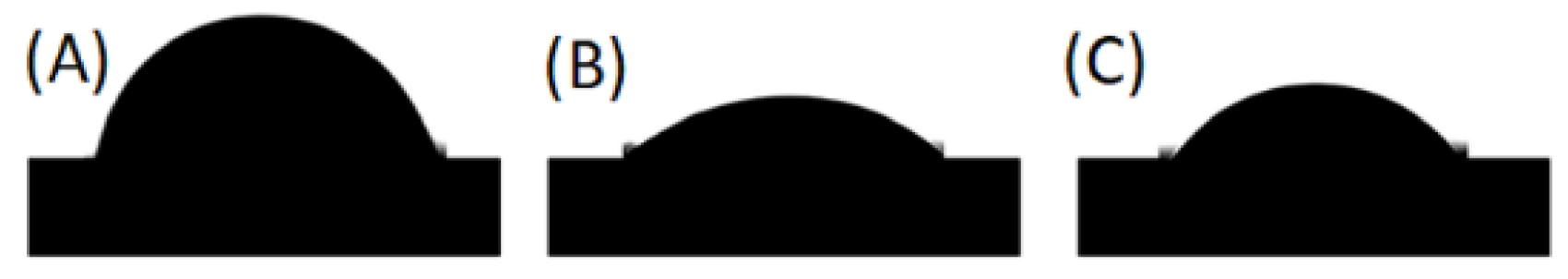
3.4. Surface Wettability of Coatings

Surface wettability, arising from the balance between adhesive and cohesive forces, is another important property that influences the corrosion properties and biological response of bio-implants. Surface wettability of a substrate can be described using the water contact angle (CA); where, in general, CA below 90 degree denotes hydrophilic surface and above 90 degree denotes hydrophobic surface. Figure 7 shows the CA images of water droplets on fabricated samples. The measured water CA of bare ZK60 is 77.4 ± 2.65 degree, which indicates the surface of the sample to be weakly hydrophilic, consistent with literature reports for Mg alloys [37]. With HA coating, the CA of the sample decreased to 32.9 ± 1.52 degree, making the surface strongly hydrophilic; where, the CA is greatly influenced by the hydroxyl functional groups of HA and also surface microroughness. Conversely, with subsequent SF coating, the CA value of the sample increased to 49.9 ± 1.69 degree, which denotes marginally decreased hydrophilicity because of the formation of β-sheet structure in the SF layer, as revealed by XRD results. It has been reported that cellular attachment is observed to be high on weakly hydrophilic surfaces (i.e., around 60 degree) due to an increased adsorption of extracellular matrix proteins [38]. Therefore, the fabricated SF + HA hybrid coating may not only influence corrosion resistance properties but also cell interaction properties.

3.5. In Vitro Degradation Resistance of Coatings

The in vivo performance and longevity of bio-implants is largely influenced by their stability in biological fluids at physiological pH and osmotic pressure. In aqueous solutions, Mg and its alloys generate H2 gas and Mg2+ ions, which leads to an increase in the pH of the solution [34,39]. To study the stability or degradability of bare, HA, and SF + HA layer on ZK60 Mg alloy specimens in simulated body fluids, the fabricated samples were immersed in the solution of Hank’s balanced salt (maintained at 37 ± 0.5 °C), and their weight and solution pH was measured periodically over a period of 28 days. With an increase in time, the pH of the solution was observed to increase for all samples (Figure 8A); where, higher pH denotes higher dissolution of Mg2+. The solution with bare ZK60 showed a rapid increase in pH for the first 5 days, which indicates rapid dissolution of Mg2+, followed by a slightly decreased rate of pH change. With HA coating, the overall dissolution rate of Mg2+ was observed to decrease, which indicates the effectiveness of the HA layer as a barrier to rapid degradation of the sample. Moreover, the pH of the solution containing SF + HA coated ZK60 sample was measured to be stabilized after 5 days of immersion, suggesting relatively improved protection to degradation with SF coating. Figure 8B shows the weight loss result of tested substrates in Hank’s solution. The bare ZK60 sample exhibited rapid weight loss at the first two weeks of immersion (as compared to other samples), followed by decreased weight loss rate in the next two weeks; which may be linked to the formation of Ca3Mg3(PO4)4 precipitates on samples (where Ca2+ and PO43− ions in the Hanks’ solution can react with Mg2+ ions released from the substrate), thereby acting as a protecting layer [40]. The rate of weight loss was observed to significantly decrease with HA coating, which shows the effectiveness of the HA layer as a barrier to rapid degradation of the sample. Moreover, subsequent SF coating further decreased the weight loss of the substrate; where, the SF + HA coated ZK60 sample showed almost 6 times lower weight loss associated to the bare ZK60 sample. The weight loss performance of all samples is also in good agreement with the trend observed for solution pH change. Therefore, the SF + HA hybrid coating offers adequate obstruction to penetrate fluid into the main substrate surface, thereby increasing the stability of the sample in simulated body fluids.
Figure 9 shows the surface morphology of degraded samples after immersion in Hanks’ solution for 14 and 28 days. After immersion for 14 days, the bare ZK60 sample showed some cracks, pits and degradation products on the surface (Figure 9A), which significantly spread and deepened after 28 days of dipping (Figure 9B), which is also consistent with literature reports [41]. In contrast, the HA coated ZK60 sample showed a homogeneous surface coating with no cracks observed for 14 days (Figure 9C). However, the appearance of some new cracks was observed after 28 days of immersion (Figure 9D), which shows decrease in integrity of the coating over time. On the contrary, the SF + HA coated ZK60 sample showed a homogeneous surface with no cracks or damage observed after 14 and 28 days immersion (Figure 9E,F), which establishes the effective protection of SF against degradation among tested samples. Therefore, the fabricated SF + HA hybrid coating is anticipated to provide superior corrosion resistance properties.

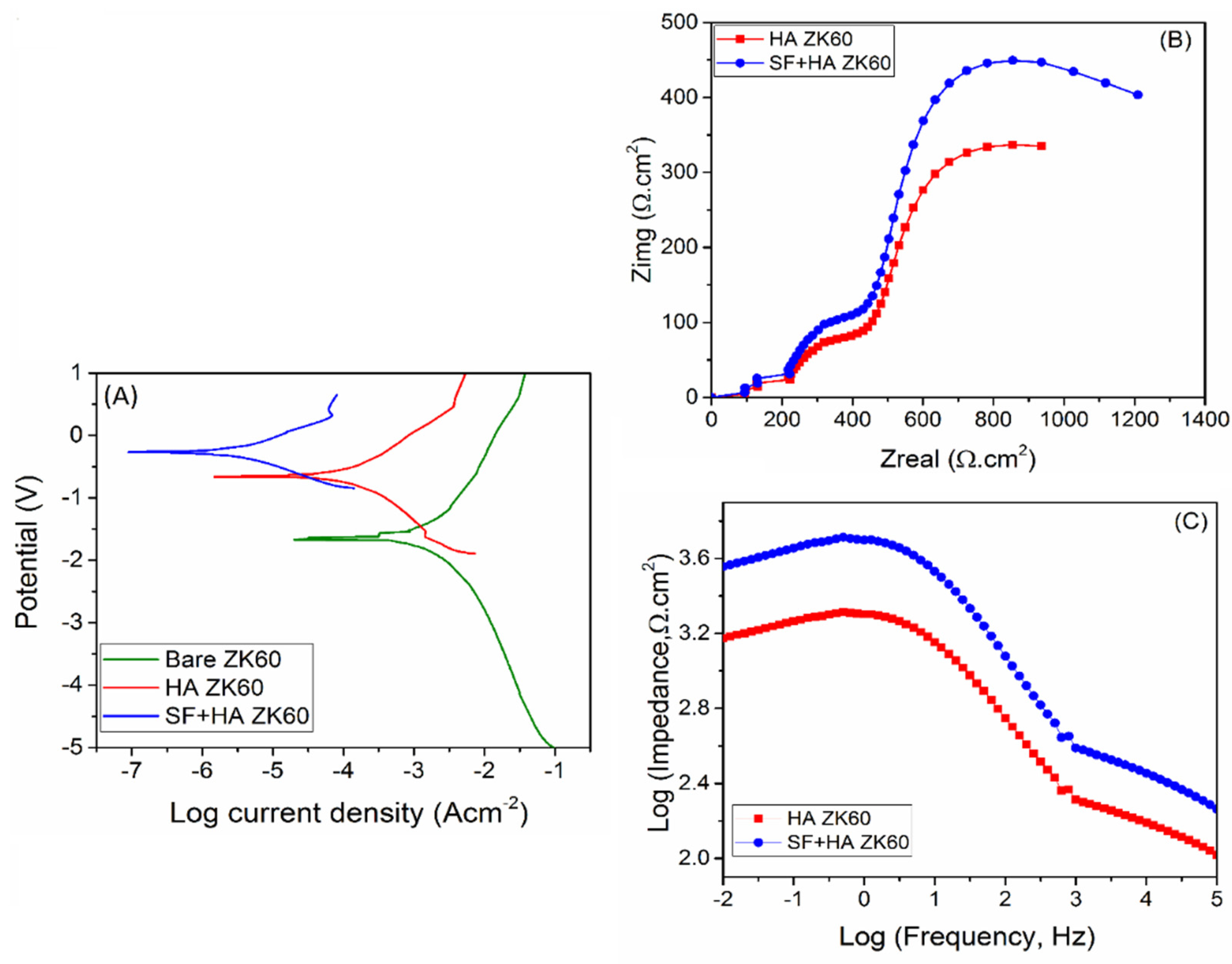
3.6. In Vitro Corrosion Performance of Coatings

The corrosion resistance performance of the coatings was studied using PDP and EIS measurements. Figure 10A shows the PDP curves of fabricated samples; where, the nobler direction of the potential represents higher corrosion resistance. The electrochemical behavior of bare ZK60 shows typical to that of active metal corrosion. The corrosion potential (Ecorr) and corrosion current density (Icorr) values obtained from PDP curves, and the calculated corrosion rate (CR) is given in Table 2. The bare ZK60 sample exhibited an Ecorr value of −1.58 V, which increased to −0.64 V with HA coating, and further to −0.25 V with subsequent SF coating [11]. This indicates a reduction in the thermodynamic tendency of ZK60 onto electrochemical corrosion with each successive coating [42]. With HA coating, the ZK60 exhibited about 78.1 times lower CR, whereas 195.2 times with SF + HA coating. Moreover, the protection efficiency (PE) of HA coating on ZK60 was calculated as 98.8%, which further increased to 99.46% with subsequent SF coating. Thus, the SF + HA hybrid coating effectively reduces ZK60 corrosion kinetics by more than two orders of magnitude, and the observed trend in corrosion resistance is in good agreement with the degradation results (pH change and weight loss).
Figure 10B,C show the Nyquist and Bode plots of fabricated samples, respectively, obtained from EIS measurements. The Nyquist plot (Figure 10B) of SF + HA coated ZK60 sample showed a larger capacitive loop in comparison with HA coated ZK60 specimen, which pointed toward greater corrosion resistance properties of the hybrid coating compared to just HA layer. The Bode impedance plot also displayed greater impedance values for SF + HA coated ZK60 sample supporting its higher corrosion resistance properties when compared to the HA coated ZK60 sample (Figure 10C) [43]. These results reveal that the SF coating efficiently acts as a supplementary barrier film, thereby further improving the corrosion resistance of HA coated ZK60 sample in Hanks’ solution [44]. Similar observation was made by Choudhury et al. [45] in their studies on sol–gel derived hybrid coatings containing three different compositions of methacrylate-phosphosilicate (M:E) on mild steel substrates (MS) as characterized using various electrochemical including potentiodynamic polarization studies. MS sample exhibited the lowest Ecorr (−0.72 V) whereas the highest Ecorr (−0.16 V) was recorded for M:E—3:7 samples. The Ecorr of the M:E—1:1 samples shift positively as high as 250 mV respectively. The shifting of the Ecorr values of all the coated samples to the noble direction in comparison to the bare MS sample indicates the enhanced corrosion resistance due to the inhibition of the anodic reaction. The efficient corrosion protection of the hybrid coatings has been ascribed to the strong interfacial interaction with the substrate and their effective barrier characteristics. In the present case, to obtain in-depth information of the contribution of each layer to corrosion resistance, impedance data was further analyzed by fitting the data to equivalent circuit models (Figure 11), which represents respective physical model of each sample.
The equivalent circuit models represent a system where polarization is due to a combination of kinetic and diffusion methods. In Figure 11, the solution resistance (Rs) between the substrate and the reference electrode; C1 and C2, and C3 represent capacitance of oxide layer, HA layer and SF layer, respectively; and Rc1, Rc2 and Rc3 represent resistance of oxide layer, HA layer and SF layer, respectively. The corrosion parameters obtained from the model fit are provided in Table 3. Compared to the HA fabricated ZK60 specimen, the SF + HA coated ZK60 sample showed increased total resistance and decreased total capacitance, which indicates increased corrosion resistance characteristics and showed a good agreement with reported literature [28,43]. The PDP and EIS test results establish that the SF + HA coated ZK60 sample presented the best corrosion resistance characteristic among the tested sample.

4. Conclusions

Our approach of surface anodization followed by layer-by-layer interfacially engineered HA and SF coatings has effectively shown to moderate the in vitro corrosion and degradation rate of ZK60 Mg alloy in SBF. The anodization of ZK60 provided an opportunity for high surface area mineralization and mechanical interlocking pathways for effective inorganic HA layer formation. The fabricated HA layer significantly improved the corrosion and weight loss resistance of ZK60, along with improved micromechanical hardness, surface hydrophilic characteristics and microroughness. The strong interfacial bonding interaction between the middle HA layer and spin coated outer SF layer further improved the integrity and stability of the coatings, along with decreased hydrophilicity, thereby further enhancing the corrosion and weight loss resistance of ZK60 in simulated body fluid. The layer-by-layer fabrication approach also provides an opportunity for tuning the physicochemical properties of each layer gradually to specific needs. The developed hybrid coatings have the potential to improve in vivo stability and longevity of Mg alloy implants and expand their potential in the field of biomedical engineering.

Author Contributions

Conceptualization and design of the manuscript, M.R., R.B., N.K.D., N.R.C.; Research supervision, N.R.C.; Writing–Original draft, M.R.; Writing–Review and editing, R.B., N.K.D., N.R.C.; All authors have read and agreed to the published version of the manuscript.

Funding

This research received no external funding.

Informed Consent Statement

Not applicable.

Data Availability Statement

The datasets generated for this study are available on request to the corresponding author.

Acknowledgments

The author would like to express gratitude to the RMIT University, Australia, for awarding M.R. with vice-chancellor PhD scholarship and giving research funding and supports to perform this work. The authors also acknowledge the facilities and technical assistance of the Micro-Nano Research Facility, Centre for Nanoscale Bio-photonics and Microscopy and Microanalysis Facility (RMIT University, Melbourne).

Conflicts of Interest

The authors proclaim no conflict of interest.

References

  1. Sezer, N.; Evis, Z.; Kayhan, S.M.; Tahmasebifar, A.; Koç, M. Review of magnesium-based biomaterials and their applications. J. Magnes. Alloy. 2018, 6, 23–43. [Google Scholar] [CrossRef]
  2. Rahman, M.; Li, Y.; Wen, C. HA coating on Mg alloys for biomedical applications: A review. J. Magnes. Alloy. 2020, 8, 929–934. [Google Scholar] [CrossRef]
  3. Chellan, P.; Sadler, P.J. The elements of life and medicines. Philos. Trans. R. Soc. A 2015, 373, 20140182. [Google Scholar] [CrossRef] [PubMed]
  4. Chakraborty Banerjee, P.; Al-Saadi, S.; Choudhary, L.; Harandi, S.E.; Singh, R. Magnesium implants: Prospects and challenges. Materials 2019, 12, 136. [Google Scholar] [CrossRef] [PubMed] [Green Version]
  5. Rahman, M.; Dutta, N.K.; Roy Choudhury, N. Magnesium alloys with tunable interfaces as bone implant materials. Front. BioEng. Biotechnol. 2020, 8, 564. [Google Scholar] [CrossRef] [PubMed]
  6. Cao, W.-T.; Ma, C.; Mao, D.-S.; Zhang, J.; Ma, M.-G.; Chen, F. Mxene-reinforced cellulose nanofibril inks for 3D-printed smart fibres and textiles. Adv. Funct. Mater. 2019, 29, 1905898. [Google Scholar] [CrossRef]
  7. Riaz, U.; Shabib, I.; Haider, W. The current trends of Mg alloys in biomedical applications—A review. J. Biomed. Mater. Res. 2019, 107, 1970–1996. [Google Scholar] [CrossRef] [PubMed]
  8. Czerwinski, F. Magnesium Alloys: Properties in Solid and Liquid States; IntechOpen: Rijeka, Croatia, 2014. [Google Scholar]
  9. Blawert, C.; Dietzel, W.; Ghali, E.; Song, G. Anodizing treatments for magnesium alloys and their effect on corrosion resistance in various environments. Adv. Eng. Mater. 2006, 8, 511–533. [Google Scholar] [CrossRef]
  10. Song, Y.; Zhang, S.; Li, J.; Zhao, C.; Zhang, X. Electrodeposition of Ca–P coatings on biodegradable Mg alloy: In vitro biomineralization behavior. Acta Biomater. 2010, 6, 1736–1742. [Google Scholar] [CrossRef]
  11. Rahman, M.; Li, Y.; Wen, C. Realization and characterization of double-layer Ca-P coating on WE43 Mg alloy for biomedical applications. Surf. Coat. Technol. 2020, 398, 126091. [Google Scholar] [CrossRef]
  12. Li, K.; Wang, B.; Zhou, J.; Li, S.-Y.; Huang, P.-r. In vitro corrosion resistance and cytocompatibility of Mg66Zn28Ca6 amorphous alloy materials coated with a double-layered nHA and PCL/nHA coating. Colloids Surf. B Biointerfaces 2020, 196, 111251. [Google Scholar] [CrossRef] [PubMed]
  13. Wang, C.; Fang, H.; Qi, X.; Hang, C.; Sun, Y.; Peng, Z.; Wei, W.; Wang, Y. Silk fibroin film-coated Mg-Ca-Zn alloy with enhanced in vitro and in vivo performance prepared using surface activation. Acta Biomater. 2019, 91, 99–111. [Google Scholar] [CrossRef] [PubMed]
  14. Yamaguchi, M. Role of zinc in bone formation and bone resorption. J. Trace Elem. Exp. Med. 1998, 11, 119–135. [Google Scholar] [CrossRef]
  15. Chen, Y.; Roohani-Esfahani, S.-I.; Lu, Z.; Zreiqat, H.; Dunstan, C.R. Zirconium ions up-regulate the BMP/SMAD signaling pathway and promote the proliferation and differentiation of human osteoblasts. PLoS ONE 2015, 10, e0113426. [Google Scholar] [CrossRef]
  16. Lu, W.; Chen, Z.; Huang, P.; Yan, B.; Yan, B. Microstructure, corrosion resistance and biocompatibility of biomimetic HA-based Ca-P coatings on ZK60 magnesium alloy. Int. J. Electrochem. Sci. 2012, 7, 12668–12679. [Google Scholar]
  17. Lu, W.; Ou, C.; Zhan, Z.; Huang, P.; Yan, B.; Chen, M. Microstructure and in vitro corrosion properties of ZK60 magnesium alloy coated with calcium phosphate by electrodeposition at different temperatures. Int. J. Electrochem. Sci. 2013, 8, 10746–10757. [Google Scholar]
  18. Wang, Z.-X.; Xu, L.; Zhang, J.-W.; Ye, F.; Lv, W.-G.; Xu, C.; Lu, S.; Yang, J. Preparation and degradation behavior of composite bio-coating on ZK60 magnesium alloy using combined micro-arc oxidation and electrophoresis deposition. Front. Mater. 2020, 7, 190. [Google Scholar] [CrossRef]
  19. Jin, W.; Hao, Q.; Peng, X.; Chu, P.K. Enhanced corrosion resistance and biocompatibilty of PMMA-coated ZK60 magnesium alloy. Mater. Lett. 2016, 173, 178–181. [Google Scholar] [CrossRef]
  20. Whittaker, J.L.; Balu, R.; Knott, R.; de Campo, L.; Mata, J.P.; Rehm, C.; Hill, A.J.; Dutta, N.K.; Roy Choudhury, N. Structural evolution of photocrosslinked silk fibroin and silk fibroin-based hybrid hydrogels: A small angle and ultra-small angle scattering investigation. Int. J. Biol. Macromol. 2018, 114, 998–1007. [Google Scholar] [CrossRef]
  21. Gu, X.N.; Li, N.; Zhou, W.R.; Zheng, Y.F.; Zhao, X.; Cai, Q.Z.; Ruan, L. Corrosion resistance and surface biocompatibility of a microarc oxidation coating on a Mg–Ca alloy. Acta Biomater. 2011, 7, 1880–1889. [Google Scholar] [CrossRef]
  22. ASTM G31-72(2004); Standard Practice for Laboratory Immersion Corrosion Testing of Metals. ASTM International: West Conshohocken, PA, USA, 2004.
  23. Aramaki, K. An attempt to prepare nonchromate, self-healing protective films containing molybdate on iron. Corrosion 1999, 55, 1020–1030. [Google Scholar] [CrossRef]
  24. Wang, T.; Yang, G.; Zhou, W.; Hu, J.; Jia, W.; Lu, W. One-pot hydrothermal synthesis, in vitro biodegradation and biocompatibility of Sr-doped nanorod/nanowire hydroxyapatite coatings on ZK60 magnesium alloy. J. Alloys Compd. 2019, 799, 71–82. [Google Scholar] [CrossRef]
  25. Gao, F.; Xu, C.; Hu, H.; Wang, Q.; Gao, Y.; Chen, H.; Guo, Q.; Chen, D.; Eder, D. Biomimetic synthesis and characterization of hydroxyapatite/graphene oxide hybrid coating on Mg alloy with enhanced corrosion resistance. Mater. Lett. 2015, 138, 25–28. [Google Scholar] [CrossRef]
  26. Xiong, P.; Jia, Z.; Li, M.; Zhou, W.; Yan, J.; Wu, Y.; Cheng, Y.; Zheng, Y. Biomimetic Ca, Sr/P-doped silk fibroin films on Mg-1Ca alloy with dramatic corrosion resistance and osteogenic activities. ACS Biomater. Sci. Eng. 2018, 4, 3163–3176. [Google Scholar] [CrossRef] [PubMed]
  27. Zhang, S.; Bi, Y.; Li, J.; Wang, Z.; Yan, J.; Song, J.; Sheng, H.; Guo, H.; Li, Y. Biodegradation behavior of magnesium and ZK60 alloy in artificial urine and rat models. Bioact. Mater. 2017, 2, 53–62. [Google Scholar] [CrossRef] [PubMed]
  28. Ji, X.-J.; Gao, L.; Liu, J.-C.; Jiang, R.-Z.; Sun, F.-Y.; Cui, L.-Y.; Li, S.-Q.; Zhi, K.-Q.; Zeng, R.-C.; Wang, Z.-L. Corrosion resistance and antibacterial activity of hydroxyapatite coating induced by ciprofloxacin-loaded polymeric multilayers on magnesium alloy. Prog. Org. Coat. 2019, 135, 465–474. [Google Scholar] [CrossRef]
  29. Wang, J.; Liu, Y.; Fan, Z.; Wang, W.; Wang, B.; Guo, Z. Ink-based 3D printing technologies for graphene-based materials: A review. Adv. Compos. Hybrid Mater. 2019, 2, 1–33. [Google Scholar] [CrossRef] [Green Version]
  30. Fang, H.; Wang, C.; Zhou, S.; Zheng, Z.; Lu, T.; Li, G.; Tian, Y.; Suga, T. Enhanced adhesion and anticorrosion of silk fibroin coated biodegradable Mg-Zn-Ca alloy via a two-step plasma activation. Corros. Sci. 2020, 168, 108466. [Google Scholar] [CrossRef]
  31. Gadaleta, S.J.; Mendelsohn, R.; Paschalis, E.L.; Camacho, N.P.; Betts, F.; Boskey, A.L. Fourier transform infrared spectroscopy of synthetic and biological apatites. In Mineral Scale Formation and Inhibition; Springer: Boston, MA, USA, 1995; pp. 283–294. [Google Scholar] [CrossRef]
  32. Lu, Q.; Hu, X.; Wang, X.; Kluge, J.A.; Lu, S.; Cebe, P.; Kaplan, D.L. Water-insoluble silk films with silk I structure. Acta Biomater. 2010, 6, 1380–1387. [Google Scholar] [CrossRef] [Green Version]
  33. Kong, X.D.; Cui, F.Z.; Wang, X.M.; Zhang, M.; Zhang, W. Silk fibroin regulated mineralization of hydroxyapatite nanocrystals. J. Cryst. Growth 2004, 270, 197–202. [Google Scholar] [CrossRef]
  34. Rahman, M.; Dutta, N.K.; Choudhury, N.R. Microroughness induced biomimetic coating for biodegradation control of magnesium. Mater. Sci. Eng. C 2021, 121, 111811. [Google Scholar] [CrossRef]
  35. Schott, H. Electrokinetic studies of magnesium hydroxide. J. Pharm. Sci. 1981, 70, 486–489. [Google Scholar] [CrossRef] [PubMed]
  36. Gorbunoff, M.J.; Timasheff, S.N. The interaction of proteins with hydroxyapatite: III. Mechanism. Anal. Biochem. 1984, 136, 440–445. [Google Scholar] [CrossRef]
  37. Li, Z.; Yu, Q.; Zhang, C.; Liu, Y.; Liang, J.; Wang, D.; Zhou, F. Synergistic effect of hydrophobic film and porous mao membrane containing alkynol inhibitor for enhanced corrosion resistance of magnesium alloy. Surf. Coat. Technol. 2019, 357, 515–525. [Google Scholar] [CrossRef]
  38. Leal-Egaña, A.; Scheibel, T. Interactions of cells with silk surfaces. J. Mater. Chem. 2012, 22, 14330–14336. [Google Scholar] [CrossRef]
  39. Ng, W.F.; Chiu, K.Y.; Cheng, F.T. Effect of pH on the in vitro corrosion rate of magnesium degradable implant material. Mater. Sci. Eng. C 2010, 30, 898–903. [Google Scholar] [CrossRef]
  40. Tkacz, J.; Slouková, K.; Minda, J.; Drábiková, J.; Fintová, S.; Doležal, P.; Wasserbauer, J. Influence of the composition of the hank’s balanced salt solution on the corrosion behavior of AZ31 and AZ61 magnesium alloys. Metals 2017, 7, 465. [Google Scholar] [CrossRef] [Green Version]
  41. Sun, K.; Gao, H.; Hu, J.; Yan, Y. Effect of pH on the corrosion and crack growth behavior of the ZK60 magnesium alloy. Corros. Sci. 2020, 179, 109135. [Google Scholar] [CrossRef]
  42. Revie, R.W.; Uhlig, H.H. Thermodynamics: Corrosion Tendency and Electrode Potentials. In Corrosion and Corrosion Control; Revie, R.W., Uhlig, H.H., Eds.; John Wiley & Sons: Hoboken, NJ, USA, 2008; Volume 201, pp. 21–41. [Google Scholar]
  43. Rahman, M.M.; Balu, R.; Abraham, A.; Dutta, N.K.; Choudhury, N.R. Engineering a Bioactive Hybrid Coating for In Vitro Corrosion Control of Magnesium and Its Alloy. ACS Appl. Bio Mater. 2021, 4, 5542–5555. [Google Scholar] [CrossRef]
  44. King, A.D.; Birbilis, N.; Scully, J.R. Accurate electrochemical measurement of magnesium corrosion rates; a combined impedance, mass-loss and hydrogen collection study. Electrochim. Acta 2014, 121, 394–406. [Google Scholar] [CrossRef]
  45. Kannan, A.G.; Choudhury, N.R.; Dutta, N.K. Electrochemical performance of sol–gel derived phospho-silicate-methacrylate hybrid coatings. J. Electroanal. Chem. 2010, 641, 28–34. [Google Scholar] [CrossRef]
Figure 1. Schematic diagram of the layer-by-layer coatings (not to scale) fabrication on ZK60 Mg alloy. (A) bare, (B) anodized, (C) HA coated, and (D,E) SF + HA coated ZK60 Mg alloy specimens.
Sustainability 14 02459 g001
Figure 2. SEM micrograph (50 µm frame length) of (A) bare, (B) anodized, (C) HA coated, and (D) SF + HA coated ZK60 Mg alloy specimens. 2D surface roughness micrograph of (E) bare, (F) anodized, (G) HA coated, and (H) SF + HA coated ZK60 Mg alloy specimens.
Sustainability 14 02459 g002
Figure 3. XRD spectra of the fabricated samples.
Sustainability 14 02459 g003
Figure 4. FTIR pattern of the HA, and SF + HA coatings on ZK60 Mg alloy.
Sustainability 14 02459 g004
Figure 5. Vickers microhardness of the fabricated samples.
Sustainability 14 02459 g005
Figure 6. Schematic diagram of adhesion mechanism of engineered layers: (A) Anodized layer, (B) HA coating and (C) SF + HA coating layer on ZK60 Mg alloy.
Sustainability 14 02459 g006
Figure 7. Contact angle images of water droplets on (A) bare, (B) HA coated, and (C) SF + HA coated ZK60 Mg alloy samples.
Sustainability 14 02459 g007
Figure 8. (A) pH changes of Hank’s balanced salt solution containing fabricated samples. (B) Weight loss graph of tested substrates in Hank’s solution.
Sustainability 14 02459 g008
Figure 9. SEM images (20 μm frame length) of (A,B) bare, (C,D) HA coated, and (E,F) SF + HA coated ZK60 Mg alloy samples after 14 and 28 days immersion in Hanks’ balanced salt solution, respectively.
Sustainability 14 02459 g009
Figure 10. (A) Potentiodynamic polarization curves (PDP), (B) Nyquist plot, and (C) Bode plot of fabricated samples.
Sustainability 14 02459 g010
Figure 11. Equivalent circuit (EC) model used to analyze the EIS data of (A) HA coated, and (B) SF + HA coated ZK60 Mg alloy samples.
Sustainability 14 02459 g011
Table 1. Elemental composition of the fabricated samples obtained from EDS analysis.
SampleMg%O%C%Ca%P%N%Ca/P Ratio
HA coated ZK602.769.0-17.710.6-1.67
SF + HA coated ZK60-41.140.06.15.77.1-
Table 2. Corrosion parameters of fabricated samples obtained from PDP test.
SampleEcorr (V)Icorr (μA/cm2)CR (mm/yr)PE (%)
Bare ZK60−1.58344.027.81-
HA coated ZK60−0.644.240.1098.80
SF + HA coated ZK60−0.251.850.0499.46
Table 3. Equivalent circuit parameters of samples obtained from EIS spectra fit.
SampleRs (Ω)Rc1 (kΩ)Rc2 (kΩ)Rc3 (kΩ)C1 (μF)C2 (μF)C3 (μF)
HA coated ZK6063.050.2126.55-82.3145.55-
SF + HA coated ZK6062.770.2126.5554.8982.3145.558.45
Publisher’s Note: MDPI stays neutral with regard to jurisdictional claims in published maps and institutional affiliations.

