Article

Effects of Hydrostatic Dissolution and Seepage on the Transport and Mechanical Properties of Glauberite

1
State Key Laboratory of Geohazard Prevention and Geoenvironment Protection, Chengdu University of Technology, Chengdu 610059, China
2
Sichuan Engineering Technology Research Center of Geohazard Prevention, Chengdu 610081, China
*
Authors to whom correspondence should be addressed.
Sustainability 2022, 14(24), 16739; https://doi.org/10.3390/su142416739
Submission received: 10 October 2022 / Revised: 8 December 2022 / Accepted: 9 December 2022 / Published: 14 December 2022

Abstract

:
During the development of urban underground space in Chengdu, China, it was found that glauberite rocks in the Guankou formation of the Cretaceous system had extensive dissolution and exerted a serious impact on the safety of the project. At present, research on the transport and mechanical properties of glauberite under hydrostatic conditions in this area is limited. In this paper, the effects of hydrostatic dissolution and seepage on the transport and mechanical properties of glauberite are studied. The results show that the concentration of aqueous solution increases step by step with the increase in the dissolution time of glauberite in still water, indicating that the forward movement of the dissolution front of glauberite rock is not a continuous process and has intermittent characteristics. The dissolution and infiltration of mirabilite seriously deteriorates the physical structure of mirabilite, resulting in a decrease in elastic modulus and an increase in axial deformation, and a decrease in mechanical properties. There are a dissolution layer, dissolution front and undissolved area in the karst infiltration of calcium and mirabilite in the hydrostatic solution, so the mechanism of the calcium and mirabilite karst dissolution process is determined. Because of the dissolution characteristics of mirabilite, underground space development should prevent the uneven settlement of mirabilite, ground collapse, pit and chamber water gushing, corrosive groundwater and other geological problems.

1. Introduction

Glauberite is one of the most important salt rocks for making sodium sulfate. Glauberite contains glauberite content greater than 40% formed by the dehydration and crystallization of sulfate sediment under medium temperature and a high-pressure environment (Figure 1).
The mechanical properties of glauberite rock are of great significance to engineering geology and geotechnical engineering. Compression tests and acoustic emission monitoring were conducted on glauberite rock by researchers to show its deformation and failure characteristics [1,2,3,4]. The effects of stress and temperature on mechanical properties have been studied [5,6,7,8,9]. It has been proposed that the AE number and energy can provide important parameters for predicting the failure of glauberite rock [10]. In addition, a damage model has been proposed on the basis of experimental research in combination with the relationship between rock microcracks and permeability [11,12]. The microstructure of glauberite rock is an important factor that affects its mechanical properties [13]. The strength, deformation moduli and acoustic velocity with interior structure alteration are variations in the generation of porous media [14]. Pressure solution then plays an important role in the deformation mechanism with the presence of a saturated solution [15,16]. It is ascribed to the dissolution of grains at highly stressed boundaries, diffusion of material and crystallization of material at interfaces [17,18]. Although the mechanical properties of glauberite rock have been studied in engineering geology, geotechnical engineering, mining and other fields, there is a lack of research on how they affect underground space development. The use of mechanical test data of glauberite rock for underground space development is limited.
Salt rock is an important chemogenic rock, and many scholars have studied its dissolution characteristics. Matthew [19] and Durie and Jessen [20] studied the influence of solution concentration, natural convection and turbulence on the dissolution rate of salt rock in the process of salt rock dissolution. Cuevas [21] studied the pore characteristics and permeability of a salt rock in Spain and divided its pores into three categories according to size: sub-pores, micropores and macropores. Liu et al. [22] studied the dissolution mechanism of salt rock under gravity and established a dynamic dissolution model of salt rock under gravity. Liang et al. [23], through research on the mechanical properties of glauberite rock dissolution and infiltration, found that the permeability of glauberite rock in its dissolution process is a function of dissolution and seepage time and seepage pressure. Rong et al. [24] studied the chemical leaching of glauberite ore with ammonium carbonate solution.
Under the action of leaching, the pores, caves and weak layers formed by glauberite destroy the original structure of the rock, and the dissolved sulfate ions and chloride ions make the groundwater corrosive to a certain extent. However, most studies focus on the mechanical properties and constitutive models of salt rock [25,26,27,28]. Research results on the influence of glauberite transport and mechanical properties under hydrostatic conditions are relatively limited. In this study, a dissolution test of mirabilite calcium in an aqueous solution was carried out to analyze the variation characteristics of solution concentration and sample dissolution peak, as well as the deterioration of the mechanical properties of mirabilite calcium in an aqueous solution, and to study the karst corrosion mechanism of mirabilite calcium in an aqueous solution.

2. Methods

2.1. Seepage and Dissolution in Glauberite

Glauberite Na2Ca(SO4)2 is a kind of sulfate double-salt mineral slightly soluble in water. When interacting with water, glauberite decomposes into water-soluble Na2SO4 and water-insoluble CaSO4 (Equation (1)). When glauberite crystal contacts water, the ions in the crystalline concretion are attracted by water molecules. When such attraction exceeds the gravity between ions, the crystalline concretion of glauberite is destroyed, resulting in the transformation from solid Na2SO4 and CaSO4 crystals into free Na+, Ca2+ and SO42−. Thus, glauberite dissolves. When the free solute encounters the undissolved glauberite, the solute will crystallize again and the crystal will adhere to the surface of glauberite. Before the solution is saturated, the crystallization rate of the solute is always less than the dissolution rate. Once the solution reaches saturation, the dissolution and crystallization are in a state of dynamic equilibrium. Before the glauberite solution is saturated, the ions in the high-concentration area closer to the glauberite rock transport further away (low-solubility area).
N a 2 S O 4 C a S O 4 + x H 2 O = N a 2 S O 4 + C a S O 4 2 H 2 O + x 2 H 2 O

2.2. Equipment

The microstructure of glauberite before and after dissolution was observed by Prisma E scanning electron microscope (maximum magnification: 1,000,000 times) (Figure 2a). The mineral composition of glauberite was obtained by Rigaku UltimaIV X-ray diffractometer (Figure 2b). The uniaxial compression test of glauberite before and after dissolution was conducted with microcomputer-controlled electrohydraulic servo press (the loading rate was set as 0.002 mm/s) (Figure 2c). The solution concentration was monitored by Baume hydrometer (Figure 2d).

2.3. Test Specimens

The glauberite rock specimens were taken from the Cretaceous Guankou formation at 140–160 m in Chengdu, China. The test specimen is Φ50 mm × 100 mm ISRM international standard cylinder specimen. Before the test, the author applied a layer of silicone sealant on the top and bottom surfaces of the test specimen, so that water seeped from the side of the specimen rather than from both ends of the specimen.
Before the test, the glauberite rock specimen was composed of glauberite crystals and argillaceous cement. The glauberite crystals were coarse macro crystalline structures in snowflake and bamboo shapes, and such crystals were irregularly distributed. Glauberite crystals with glassy luster could be seen on the surface of the specimen, which was covered with a layer of “white frost”. The reason lies in that after cutting the specimen, the fracture surface was exposed to the air, and the glauberite crystals were damped, resulting in the precipitation of glauberite crystals on the fracture surface. “White frost” phenomenon is the main feature for identifying glauberite in the field.

2.4. Test Procedure

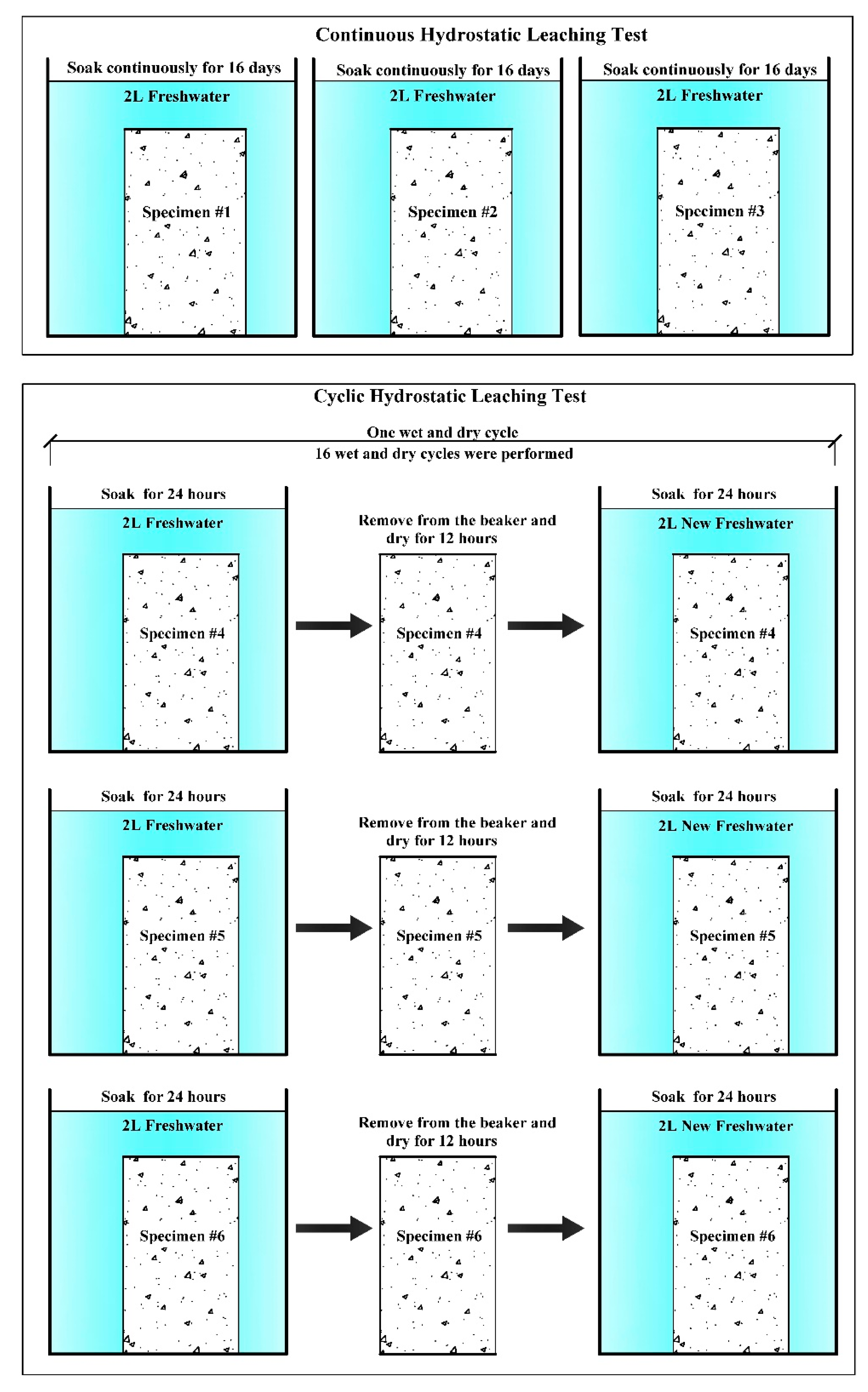
Referring to the current norms of relevant industries in China, the <Rock Test Regulations for Hydropower and Water Conservancy Projects> is widely representative, so the test methods were carried out according to the requirements of the norms. The tests conducted included continuous hydrostatic leaching test, cyclic hydrostatic leaching test and solution concentration monitoring test. The flow of continuous hydrostatic leaching test and cyclic hydrostatic leaching test is shown in Figure 3. In order to shorten the test time, after the first two tests, the author put the glauberite rock specimens that produced the dissolution layer into water, sealed the top and bottom ends of the specimens with silicone rubber to only allow side dissolution and monitored the change of solution concentration with Baume hydrometer. The PH of dissolved water for all tests was 7.2, the water temperature was 24 °C (±0.2 °C) and the indoor temperature was 25.3 °C (±0.7 °C). See Table 1 for the experimental program.
In order to explore the influence of dissolution on the strength and deformation of glauberite rock, a microcomputer-controlled electrohydraulic servo press was used to conduct uniaxial compression tests on glauberite rock specimens before and after leaching. The loading rate of all glauberite rock specimens was set as 0.002 mm/s. The uniaxial compressive strength of glauberite rock specimens, the strain corresponding to the peak strength on the uniaxial compressive stress–strain curve and the elastic modulus were obtained through the test. The elastic modulus is the slope of the straight-line segment in the stress–strain curve of uniaxial compression.

3. Test Results

3.1. Dissolution Characteristics of Glauberite Rock

3.1.1. Continuous Hydrostatic Leaching Test

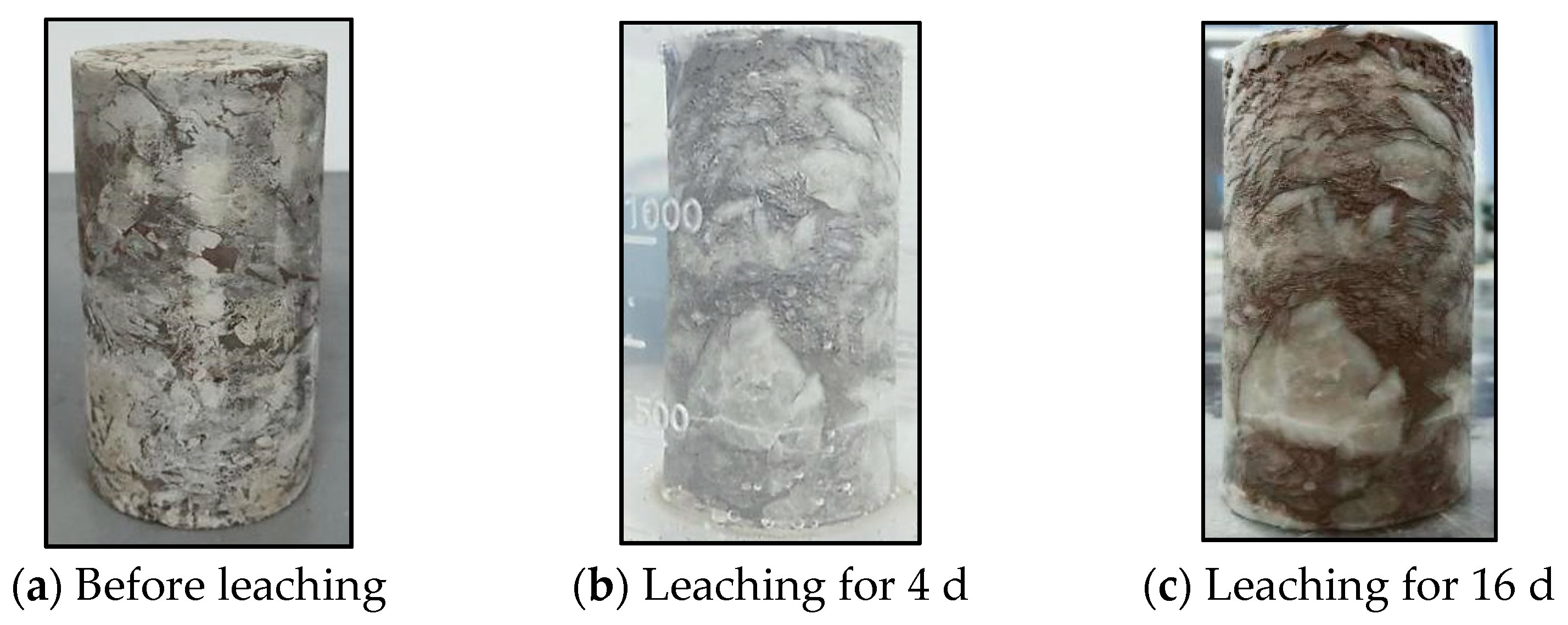
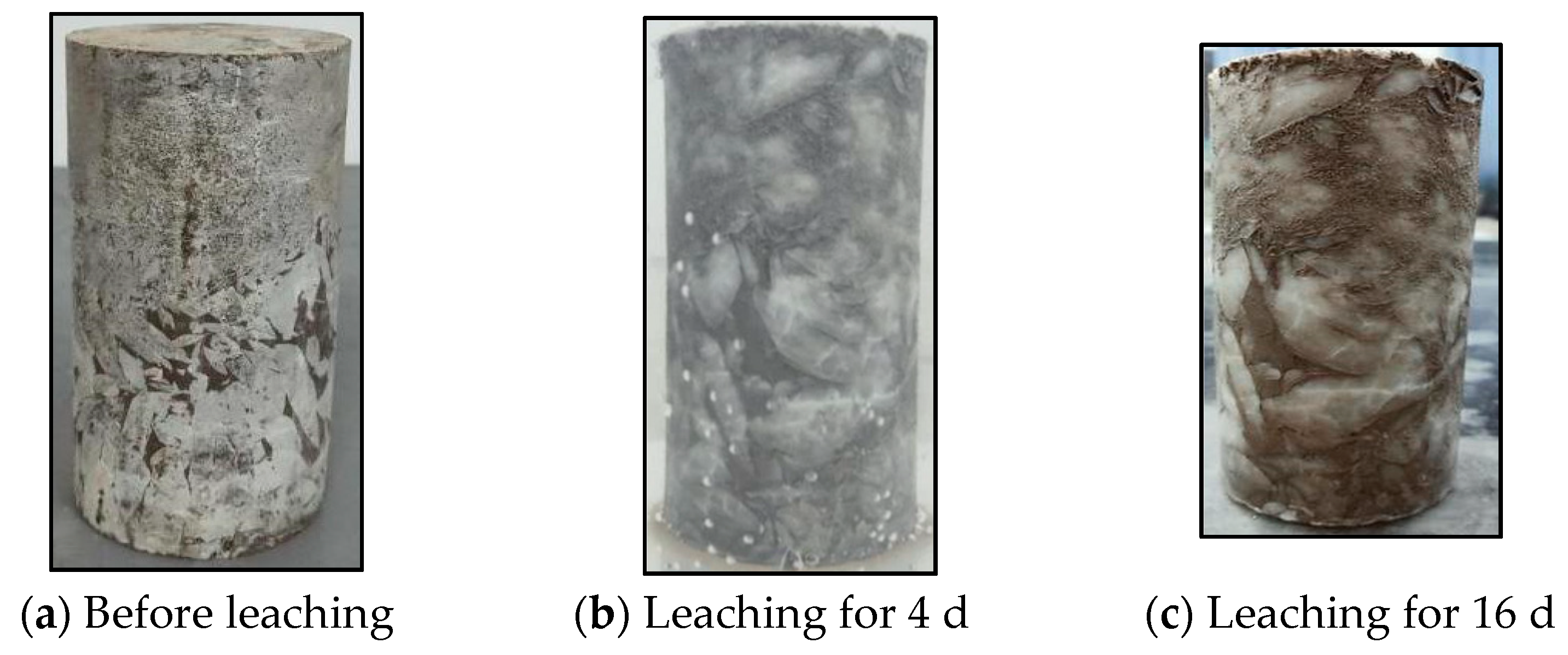
The “white frost” dissolved quickly after glauberite rock entered the water, and then the glauberite crystal recovered its glassy luster. With the extension of the leaching time, the glassy luster gradually changed to an earthy luster. The dissolution of glauberite rock led to concave and convex shapes on the surface of the specimen (Figure 4, Figure 5 and Figure 6). The larger the pit, the more glauberite rock was dissolved. The “dissolution footage” is defined as the length of the glauberite rock specimen dissolved internally. It was found that the dissolution footage in the first 4 days was significantly greater than that in the 4th–16th days. After 16 days of leaching, the dissolution charge decreased gradually along the height of the sample from top to bottom. The maximum dissolution charge was 1.5 mm, while at the lowest part of the sample, the dissolution charge was less than 0.2 mm, which shows a “differential dissolution” phenomenon in the depth direction of the sample.
After 16 days of leaching, cracks occurred in single large glauberite crystals, crystal groups, or cementation between glauberite crystal and argillaceous mud. At the end of the continuous hydrostatic leaching test, the average mass loss rate of the three glauberite rock specimens reached 12.83%.

3.1.2. Cyclic Hydrostatic Leaching Test

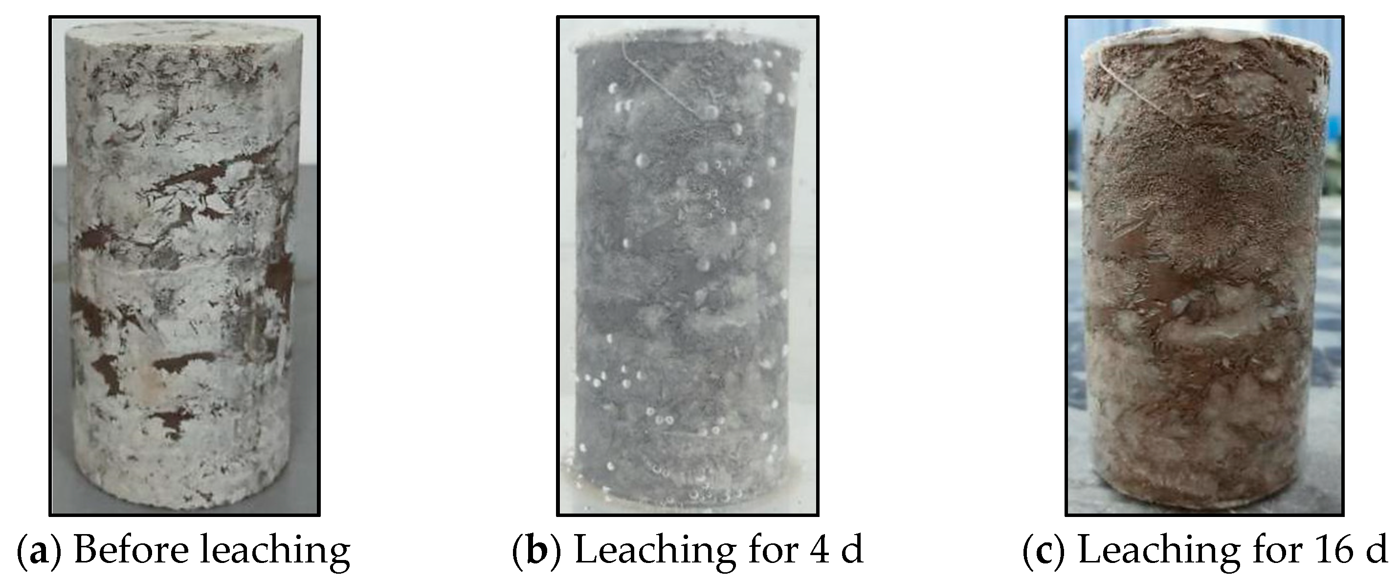
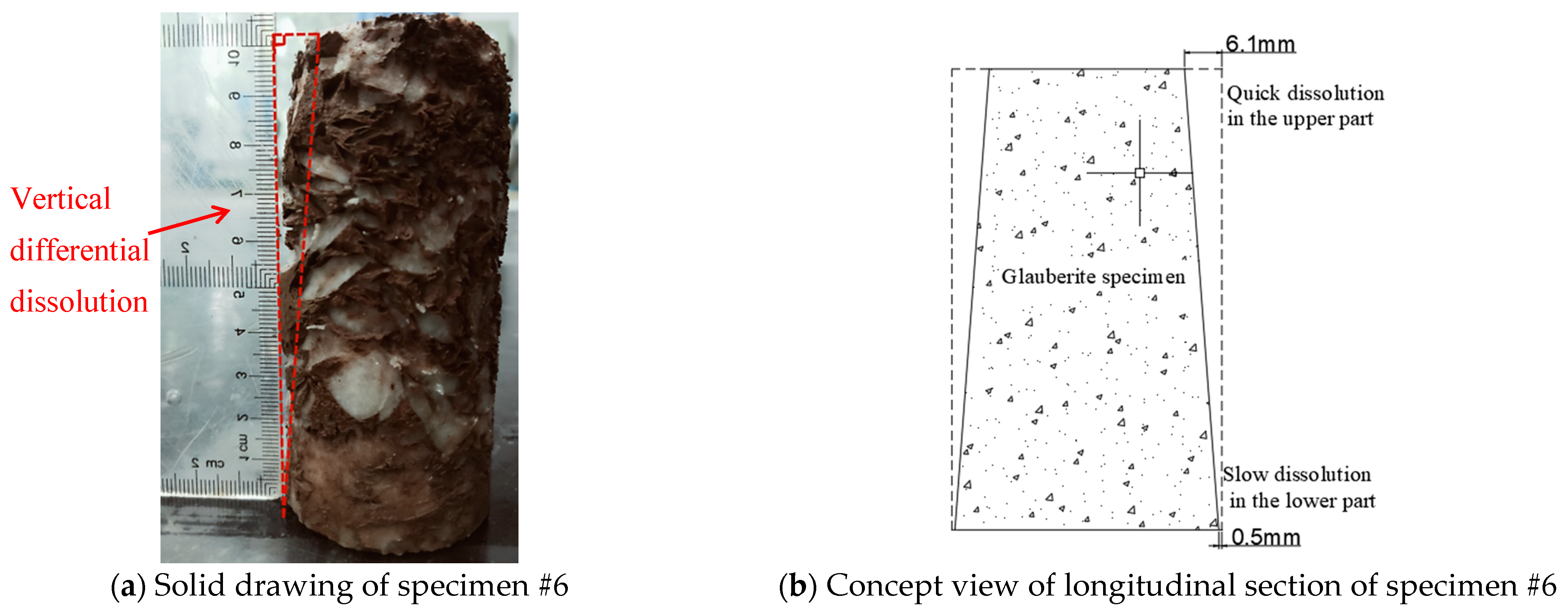
With the increase in the number of leaching cycles, the color of the glauberite rock specimen got continuously darker due to the brown argillaceous mud attached to the surface of the specimen (Figure 7, Figure 8 and Figure 9). After two cycles, the same “differential dissolution” phenomenon as that of the continuous hydrostatic leaching test occurred in the three specimens. After 16 cycles in cyclic leaching, the phenomenon of “differential dissolution” was more significant (Figure 10). The “rate of dissolution footage” is defined as the length of time it takes the glauberite rock specimen to dissolve internally in unit time (mm/d). Taking test specimen #6 as an example, after 16 days, the uppermost dissolution footage was 6.1 mm and the dissolution footage rate was 0.38 mm/d. This value is four times the rate of the same position in the continuous hydrostatic leaching test.
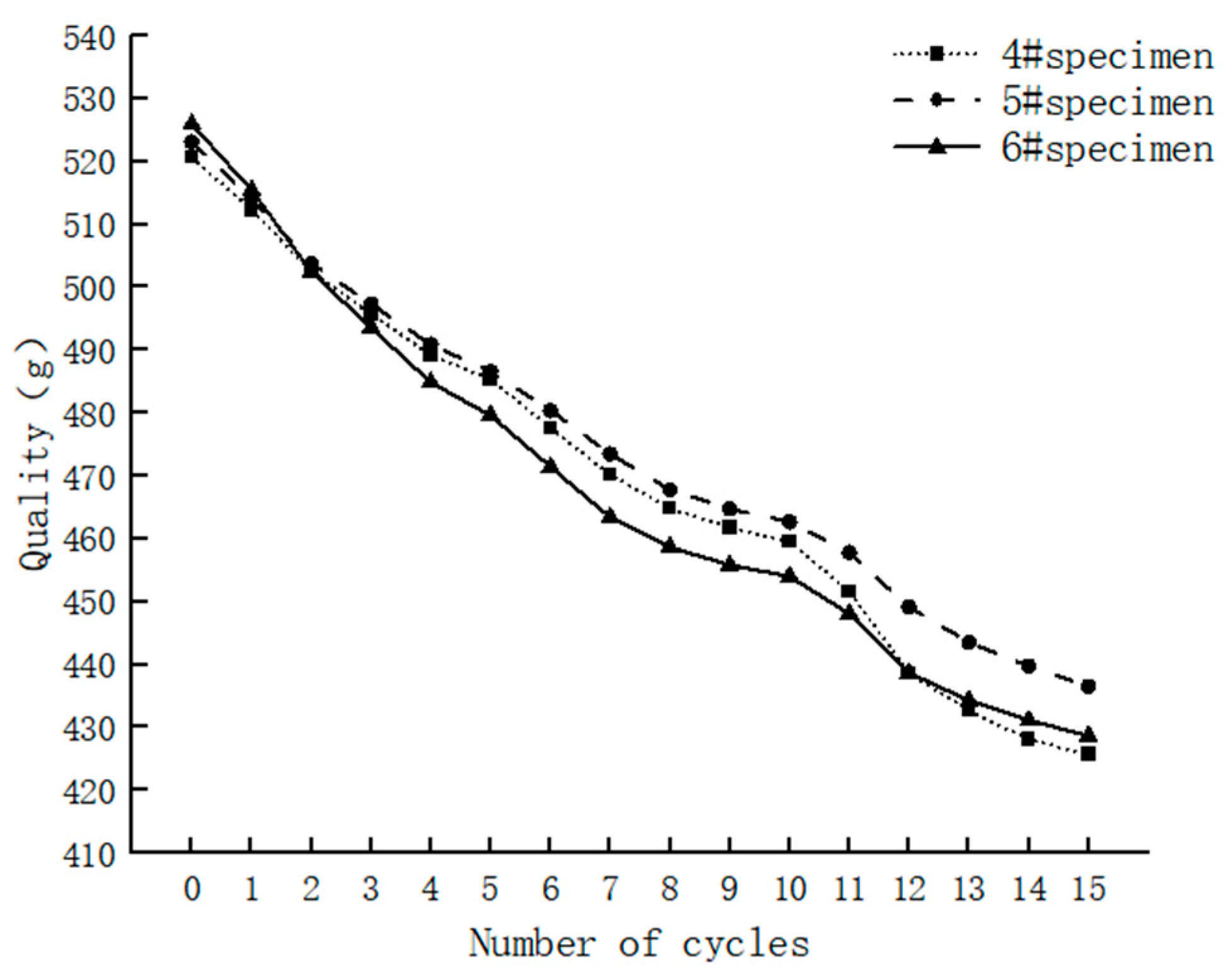
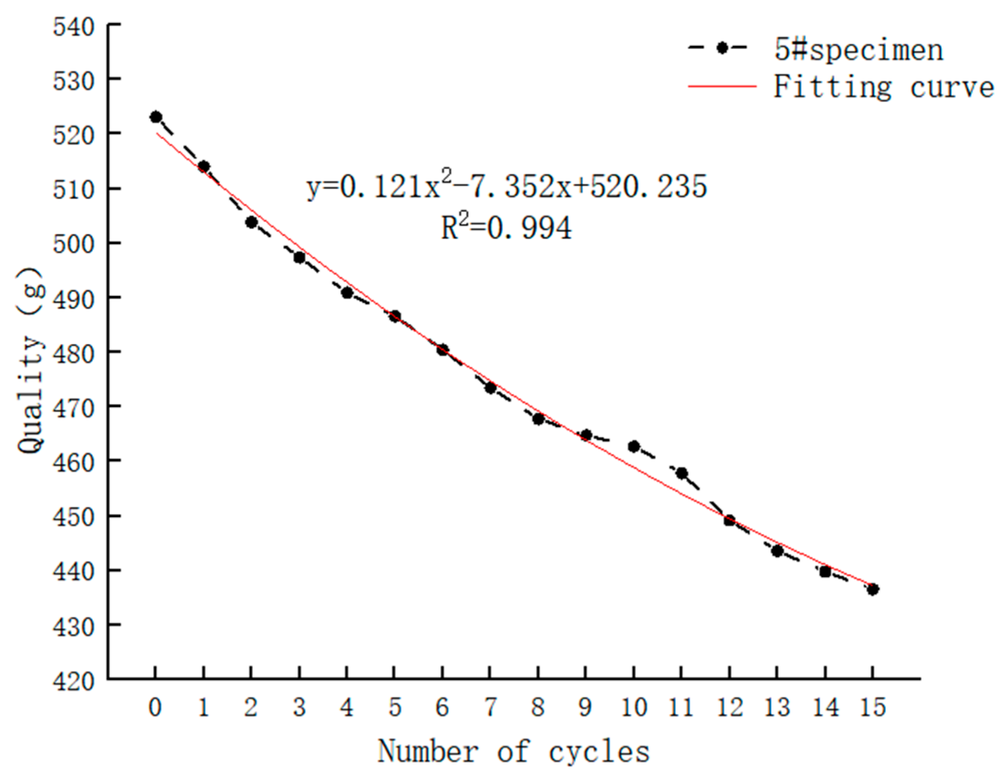
The average mass loss of each cycle in the three samples was 6.33 g, 5.77 g and 6.48 g, respectively (Figure 11). After the 15th cyclic leaching, the mass loss rate of the specimens was 18.24%, 16.55% and 18.49%, respectively, compared with the initial natural state, and the average mass loss rate was 17.76%. The sample mass change curve can be fitted as a quadratic function by Origin software (Figure 12):
y = 0.121 x 2 7.352 x + 520.235
y is the mass of the specimen and x is the number of cycles. With the increase in the number of cyclic leaching times, the mass loss of the specimen in a cycle decreases gradually. In the first three cycles of leaching, the average mass loss of the three specimens was 8.29 g/time, 8.57 g/time and 10.78 g/time, respectively. In the last three cycles, the average mass loss was 4.31 g/time, 4.22 g/time and 3.32 g/time, respectively.
Only closed cracks developed in glauberite crystals under the condition of continuous hydrostatic leaching. Under the cyclic hydrostatic leaching condition, the microcracks were further opened and developed into open cracks due to the repeated expansion of water absorption and shrinkage of water loss. With the repeated expansion after water absorption and contraction after water loss of argillaceous mud, the microcracks further opened and developed into open cracks. Taking specimen #4 as an example, a 5 cm long macrocrack with a maximum opening of 1 mm developed in the glauberite crystal at its lower part (Figure 13). Cracks La and Lb both started at the cementation between glauberite crystal and argillaceous mud. The reason for this is that there is a difference between the volumetric expansion rate of glauberite crystal after reacting with water and the volumetric expansion rate of argillaceous mud after absorbing water, resulting in the weak cementation surface. Cracks La and Lb then further expanded along the cementation surface, and finally developed into concave open cracks.

3.2. Transport Properties of Glauberite

The migration characteristics of mirabilite refer to the changes in physical structure, phase characteristics and solution concentration when mirabilite crystals dissolve into easily soluble Na2SO4 and insoluble CaSO4 under static water conditions.

3.2.1. Dissolution and Seepage Mechanism

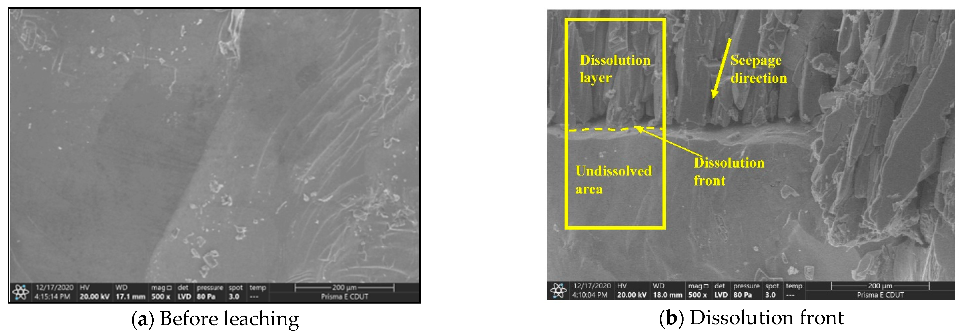
In the natural state, the structure of glauberite is very compact (Figure 14a), meaning it is low-permeability or impermeable rock. The sodium sulfate mineral in mirabilite crystals is easily soluble in water, which will lead to a change in its permeability and greatly increase its porosity after the dissolution of mirabilite. The main reason for this is that with the dissolution of sodium sulfate, calcium sulfate forms a calcium sulfate dihydrate skeleton under hydration. The skeleton is formed by several long columnar calcium sulfate dihydrate crystals arranged in parallel contact. The long-axis direction of the columnar crystal is roughly parallel to the forward direction of dissolution. The dissolution process makes the overhead space of different columnar crystals form seepage channels. The solution continues to dissolve the fresh surface of glauberite at the end of the seepage channel. Thus, the seepage channel is extended, and the thickness of the dissolution layer is increased (Figure 14b).
The interface between the dissolution layer and the non-dissolution area is the dissolution front. The calcium sulfate dihydrate columnar crystals are in incomplete contact with the non-dissolution area. The two are different types of media, so the bonding performance between the two is weak, and the shear and tensile strength are very low.

3.2.2. Phase Change Characteristics

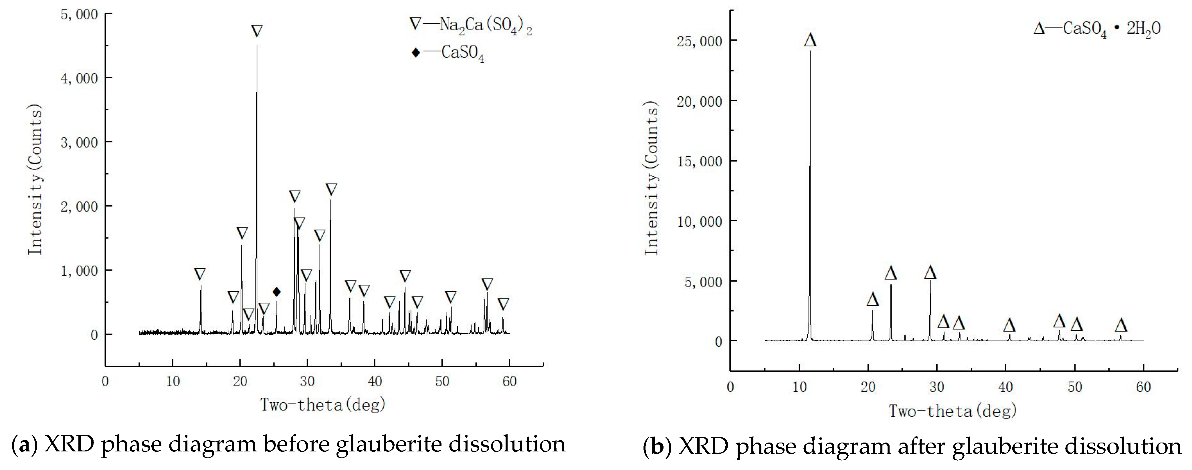
Before dissolution (i.e., in the natural state), the main component of glauberite crystal is Na2Ca(SO4)2, only containing a small amount of CaSO4 (Figure 15a). After 16 days of leaching, CaSO4•2H2O is the sole component of calcium sulfate hydrate (Figure 15b). This shows that after sufficient time of hydrostatic leaching, Na2SO4 is completely dissolved, and the residual CaSO4 skeleton is completely transformed into CaSO4•2H2O under hydration. The hydration process of CaSO4 in a freshwater solution without additives is quite slow, while the CaSO4 skeleton of glauberite can be fully hydrated in a relatively short time, which is due to the hydration activation effect of a Na2SO4 solution on CaSO4. With the increase of Na2SO4 concentration, the hydration rate of CaSO4 increases.

3.2.3. Transport Properties of Glauberite

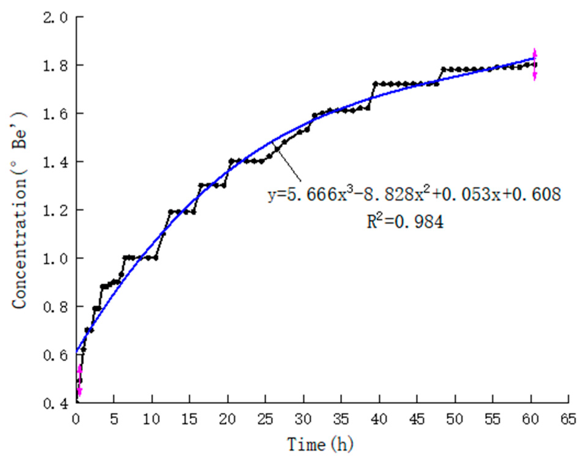
The concentration of glauberite aqueous solution changes with leaching time in an irregular step-ascending curve (Figure 16), which can be fitted into a cubic function using Origin software:
y = 5.666 x 3 8.828 x 2 + 0.053 x + 0.608
y is the solution concentration and x is the leaching time. The rise of concentration shows a jump phenomenon. The dense internal structure of calcium glauberite expands in volume due to the hydration of calcium sulfate, and new cracks are generated along the structural plane, which expose the new calcium glauberite dissolution surface, and the dissolution front pushes into the interior of the specimen. At this time, the rise rate of sodium sulfate concentration becomes faster. When the sodium sulfate on the new solution surface dissolves to a certain extent, the solution concentration increases slowly. During the cycle of the above process, the concentration rise curve appears in the step form, indicating that the dissolution front has a time-discontinuous development. The concentration rising curve shows a cubic function change law. Due to the dissolution inhibition effect caused by the reduction in concentration difference and the increase in the thickness of the dissolution layer, the rising rate of concentration gradually decreases with time.

3.3. Mechanical Properties of Glauberite Rock

3.3.1. Mechanical Properties before Dissolution

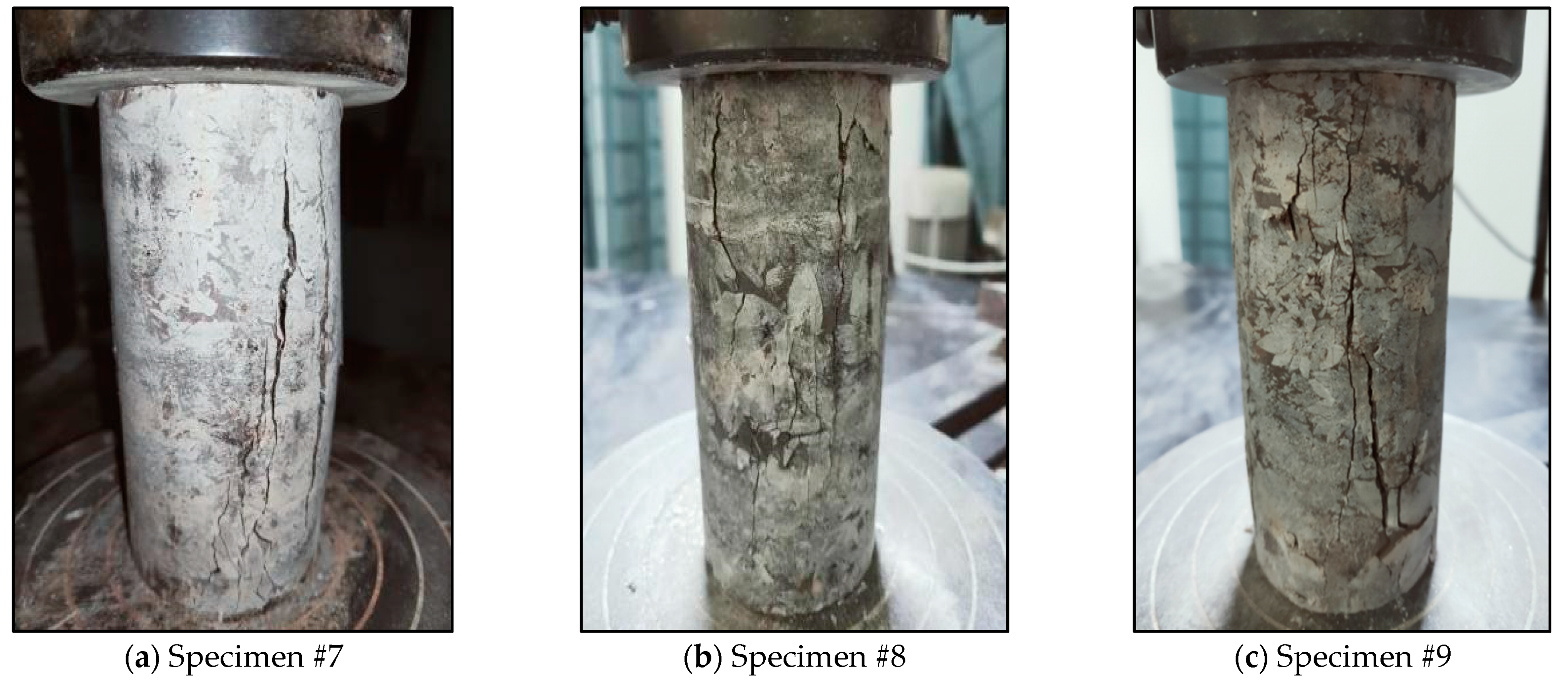
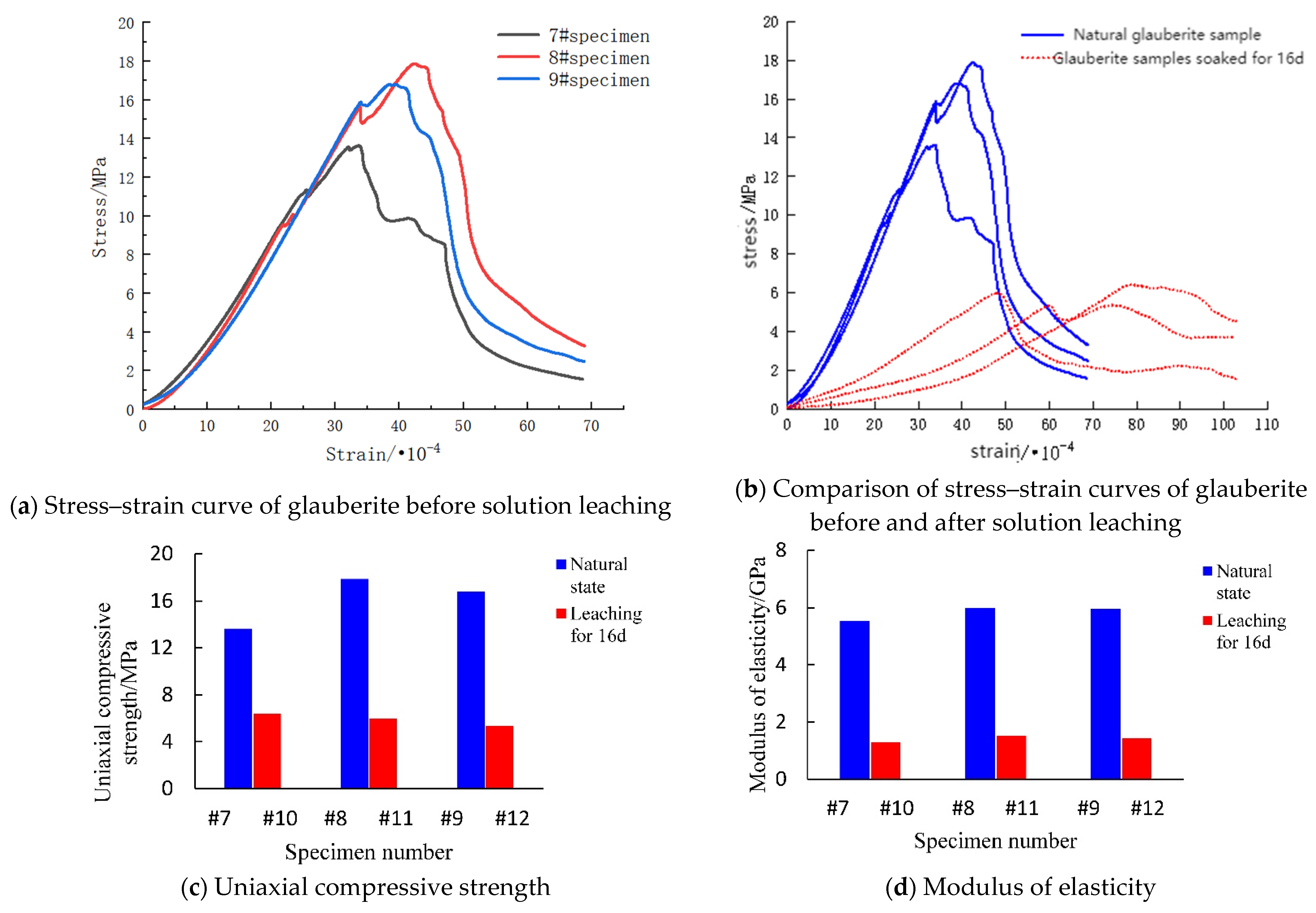
Three glauberite rock specimens, numbered specimen #7, #8 and #9 before the leaching test, were selected for the uniaxial compression test. The uniaxial failure mode of the three specimens was longitudinal splitting failure (Figure 17a–c). This is due to the circumferential stress generated by the samples of glauberite under the continuous axial compression load. The average uniaxial compressive strength of glauberite rock specimens in their natural state is 16.11 MPa, and the average elastic modulus is 5.824 GPa. According to China’s Code for Investigation of Geotechnical Engineering, it belongs to the soft rock category.
The deformation process of glauberite rock under uniaxial compression is divided into four stages (Figure 18a): (1) In the pore and fissure compaction stage, the primary pore and fissure gradually close under axial compression load, and the slope of the stress–strain curve becomes larger. There are many primary structural planes in glauberite crystal, so the compaction phenomenon of glauberite rock is more obvious than that of other rocks. (2) Elastic deformation and stable development stage of microcracks. At this stage, the stress–strain curve is approximately linear. (3) In the progressive fracture stage, the specimen begins to develop from elasticity to plasticity; the volume of the specimen also changes from compression to expansion, and the microfracture develops into macrocracks until the specimen fails. During the development of the slope of the stress–strain curve at this stage, a small segment of abnormality occurs. To be specific, the phenomenon of “stress drop-rebound” occurs in all three specimens, and the moment of stress drop is accompanied by a brittle sound, which is exactly the time when the first apparent splitting crack of the specimen occurs. The reason for the phenomenon of “stress drop-rebound” may be summarized as follows: a relatively weak surface of glauberite rock specimen is first tensioned and cracked, resulting in a sudden reduction in the strength of the test specimen, but it will not cause a large loss of the overall strength of the test specimen. The stress of the specimen is then adjusted as a whole, and the stress rises rapidly until reaching the peak value. (4) In the post-failure stage, multiple macrofracture surfaces develop in the specimen, the stress does not show a linear decrease, and there is a certain axial strain, showing that glauberite has good plasticity.

3.3.2. Mechanical Properties after Dissolution

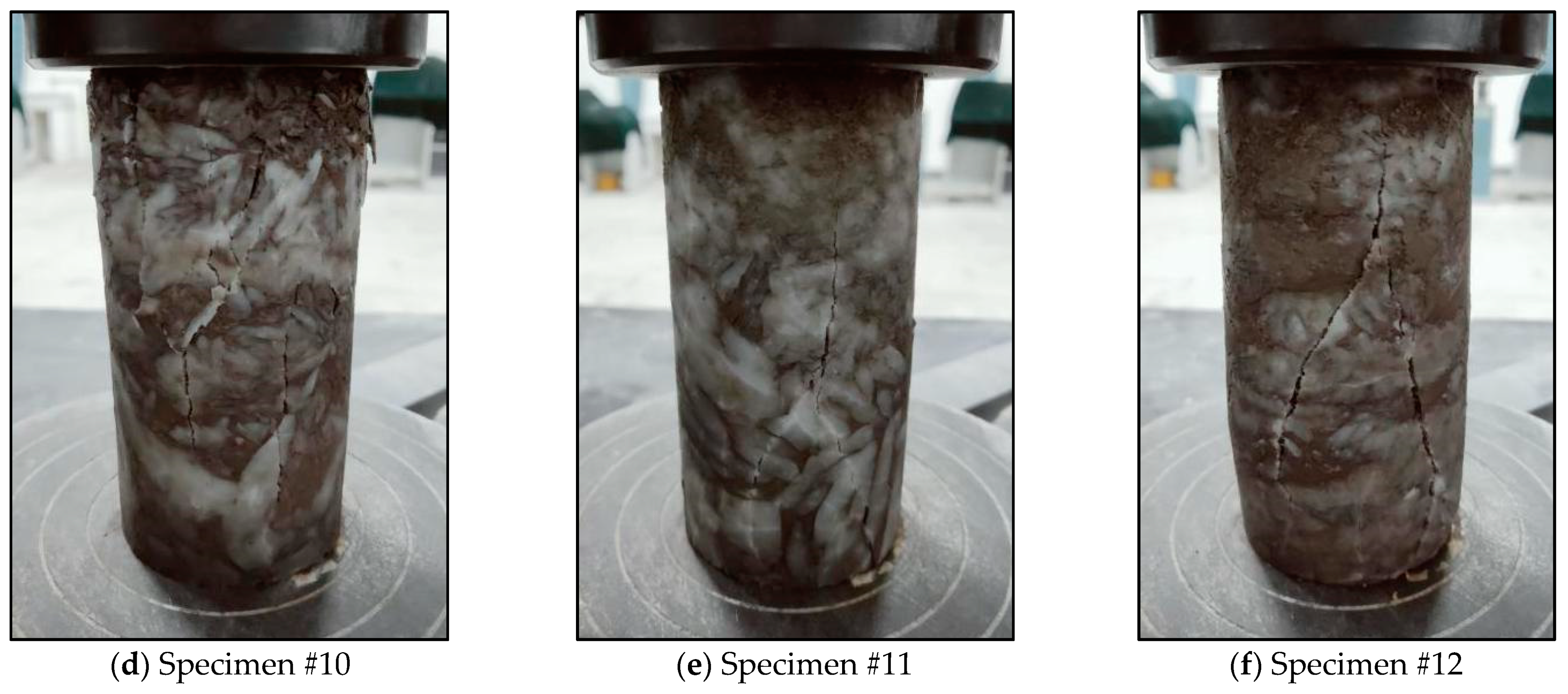
Because the end face of the specimen after cyclic leaching becomes smaller, the uniaxial compression test will have a large error, so the uniaxial compression specimen after leaching of glauberite selects the sample used in the continuous hydrostatic leaching test (specimens #10, #11 and #12). After leaching, the “Y” shaped fracture occurs on the surface of the glauberite rock specimen (Figure 17d–f), indicating that its uniaxial compression failure mode includes shear failure and tensile failure. The reason for the shear failure is the defective effect caused by the dissolution of calcium mannite. The failure mode of glauberite rock after leaching changes from brittle failure to plastic failure. It can be seen from the stress–strain curve (Figure 18b) that the stress of the specimen decreases slowly after failure, and it still has the ability to bear a certain load in a short time. After leaching, the average uniaxial compressive strength of the sample is only 5.90 MPa (Figure 18c), which is 63% lower than that of the sample before dissolution; the average peak strain is 75% higher than that of the specimen under its natural state; and the average elastic modulus is 76% lower than that under its natural state (Figure 18d). The results show that long-time leaching degrades the glauberite as a whole, and the axial deformation increases obviously under the compression load.

4. Discussion

4.1. Dissolution Process Mechanism of Glauberite Rock under Hydrostatic Conditions

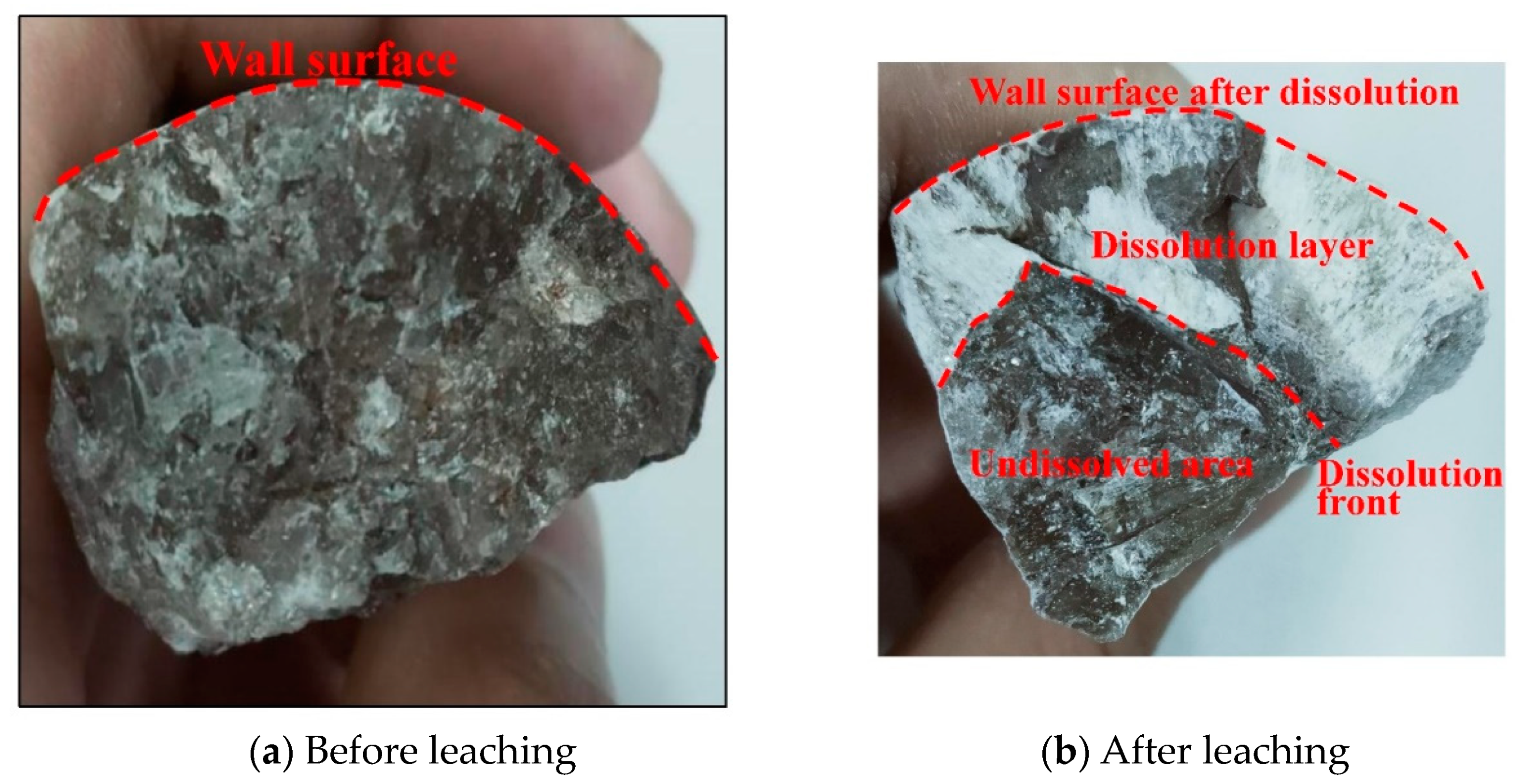
Glauberite is a double salt of sodium sulfate and calcium sulfate. The soluble sodium sulfate dissolves quickly, and then the insoluble calcium sulfate skeleton remains. Calcium sulfate forms calcium sulfate hydrate through hydration. Therefore, glauberite changes from a glassy luster to an earthy luster after hydrostatic leaching. From the cross-section of glauberite rock along the water-soluble direction (Figure 19), it can be found that the dissolution of glauberite occurs within a certain thickness from the wall. After encountering water, the dissolution of sodium sulfate on the wall makes the residual calcium sulfate hydrate skeleton have seepage channels, so that the permeability of glauberite is gradually enhanced, the sodium sulfate inside the wall is also dissolved and the seepage channels continue to expand and extend, turning the impermeable glauberite into a permeable porous medium.
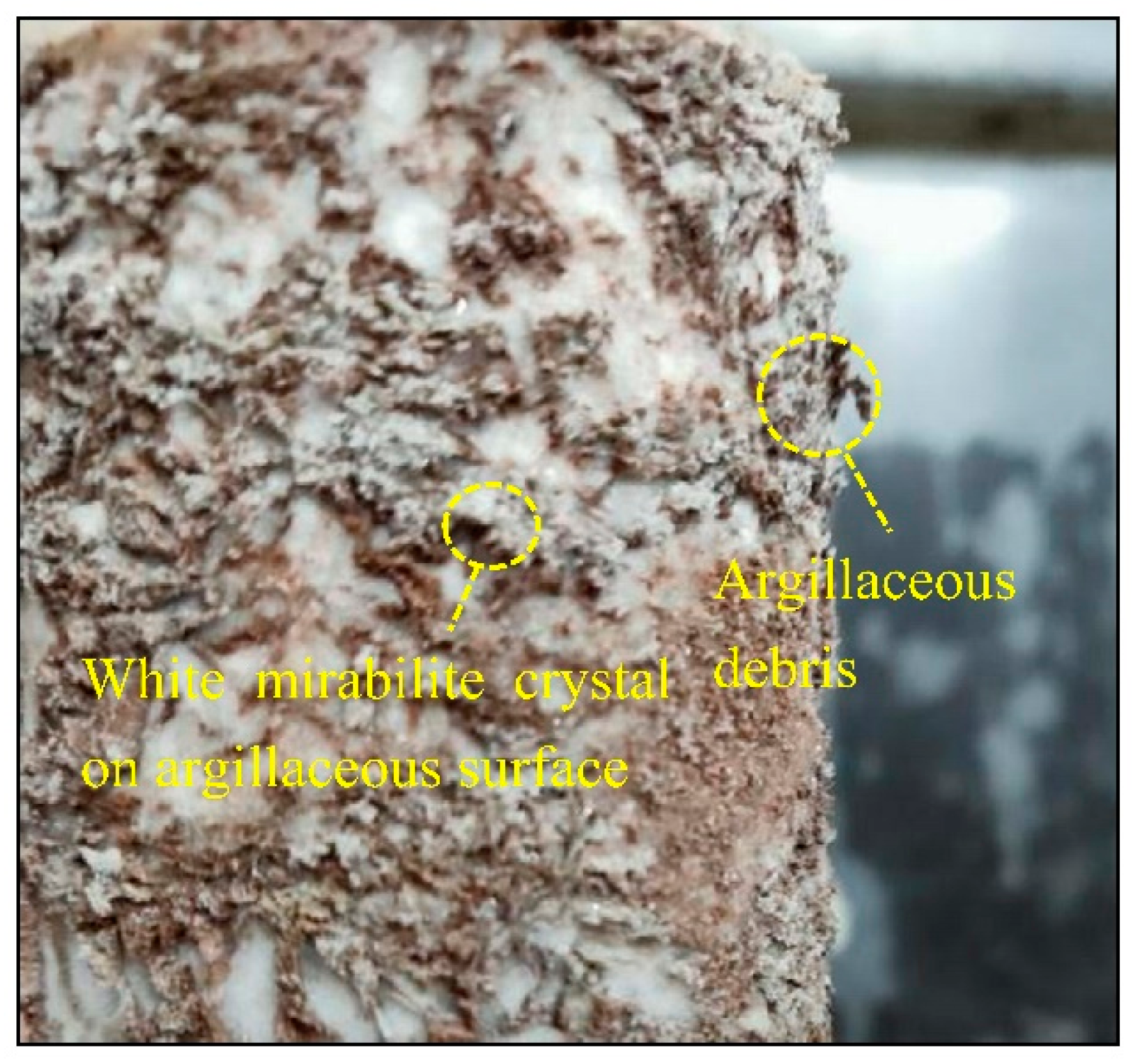
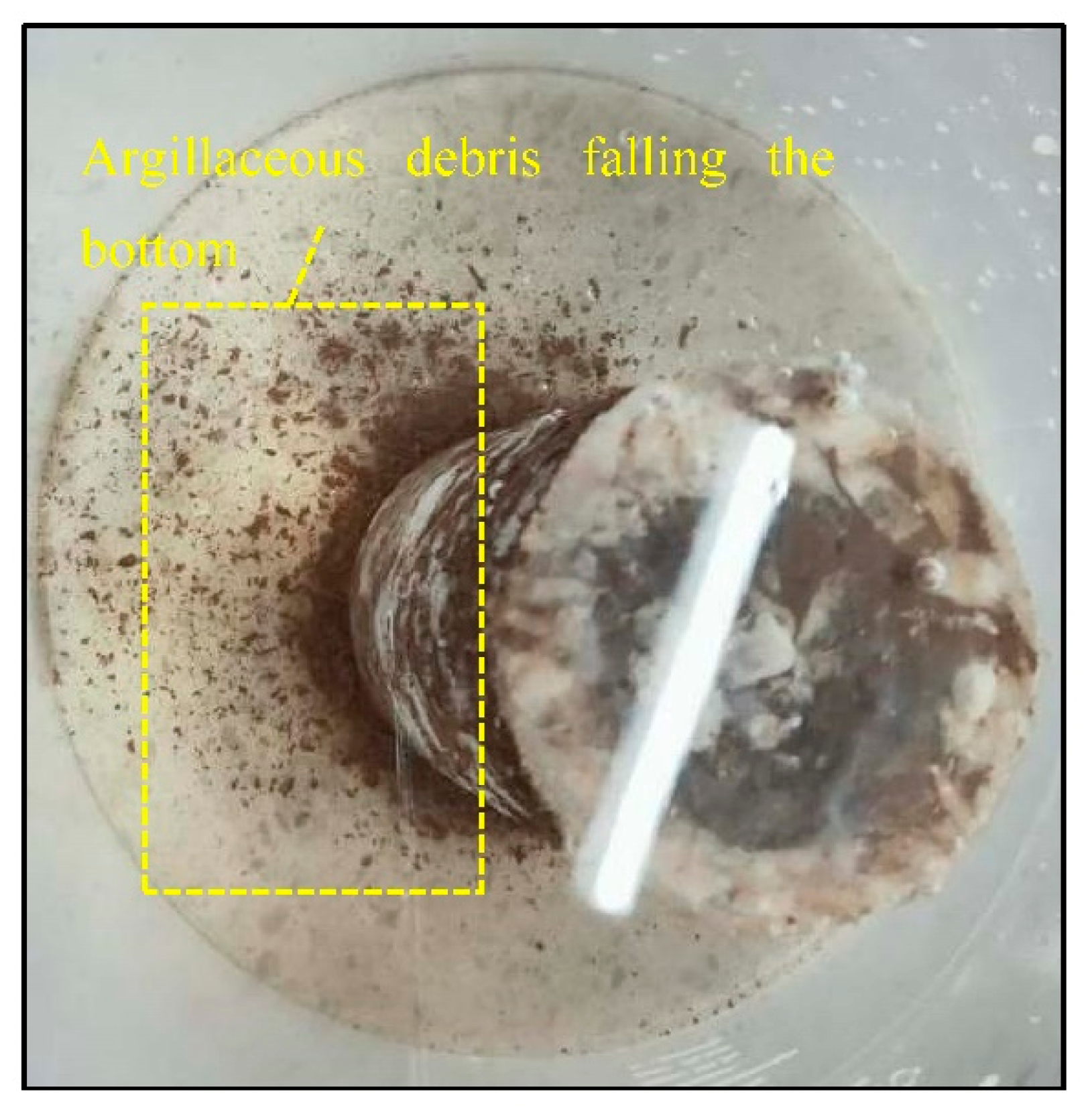
In the cyclic static water immersion test, the development of tensile cracks in specimens is only an example (Figure 13), not common. It is believed that the crystal group (crystallization condition) formed by a single large glauberite crystal or multiple glauberite crystals is an important condition for the development of tensile fractures. The cementation surface between glauberite crystal and argillaceous mud becomes the potential weak surface of tensile failure. In addition, sufficient drying–wetting cycles are the external conditions for the formation of tensile fractures. After the cyclic hydrostatic leaching test, a large number of glauberite crystals can be seen growing on the argillaceous surface during the natural drying process of the glauberite rock specimen for 12 h (Figure 20), and most of the argillaceous mud is stripped into fragments, which immediately falls off when entering water the next time (Figure 21). Clay minerals have the function of adsorption, making water solutions containing Na+ and SO42− on the argillaceous surface attach to the argillaceous surface after glauberite rock specimens leave water. In a dry environment, with the continuous evaporation of the surface-attached water, the concentration of Na2SO4 in the remaining attached water increases relatively. After reaching the supersaturation state, Na2SO4 in the liquid phase crystallizes into solid Na2SO4·10H2O (glauberite) crystal and is attached to the argillaceous surface. However, glauberite does not have the ion adsorption capacity of clay minerals, and no glauberite crystal is formed. In the process of the drying–wetting cycle, the argillaceous mud rich in clay minerals repeatedly expands after water absorption and contracts after water loss, resulting in uneven stress and local microcracks; in addition, the cracking part in argillaceous mud adsorbs water solutions containing Na+ and SO42− when soaking in water. After leaving the soaking environment, Na2SO4 precipitates into Na2SO4·10H2O crystals, with a volume increase of 3.18 times, making the original microcracks further expand and finally forming a large number of argillaceous fragments.
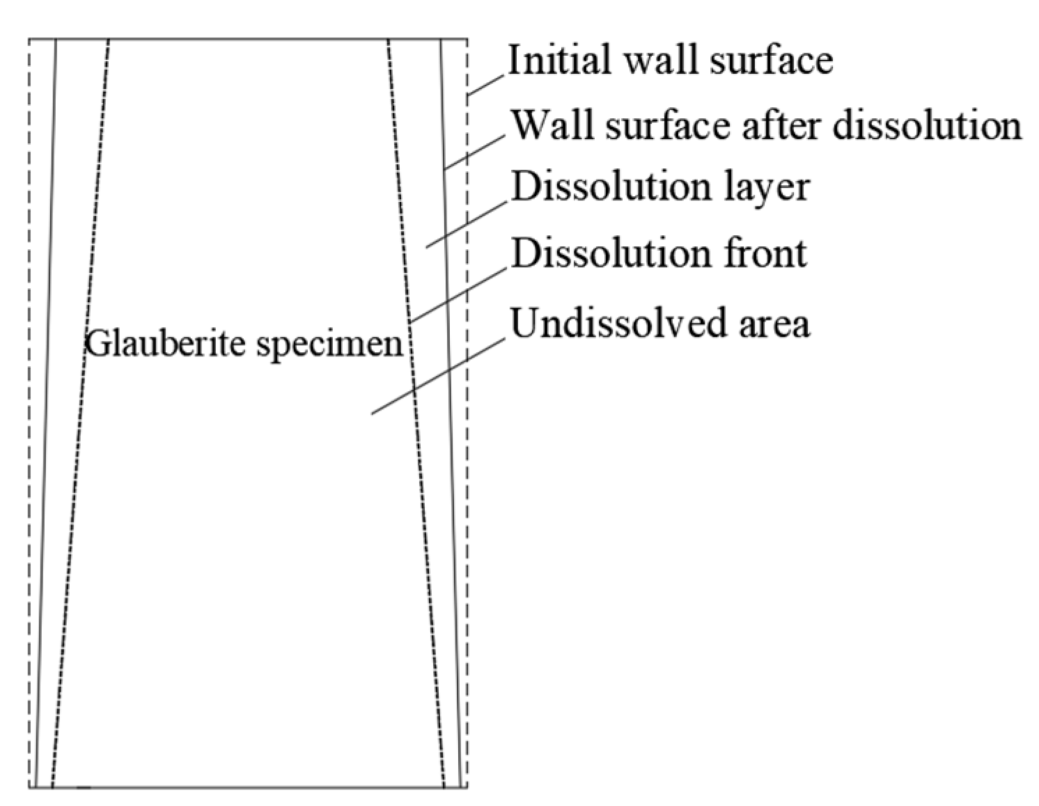
The porous media area after dissolution is defined as the “dissolution layer”. The area not affected by dissolution is defined as the “non-dissolution area”. There is a visible segmentation interface between the “dissolution layer” and the “non-dissolution area”, which is defined as the “dissolution front” (Figure 22). The “dissolution layer” is composed of white calcium sulfate hydrate and miscellaneous argillaceous insoluble matter. Although the argillaceous mud has the function of inhibiting dissolution in theory, the content of argillaceous mud cemented with glauberite crystal is small, so it thereby fails to completely block the dissolution trend of glauberite rock. The “dissolution front” is an irregularly shaped surface. Affected by the dissolution inhibition of argillaceous insolubles, it is a broken line or serrated at the cross-section of each test specimen. The contact surface between the dissolution layer and the non-dissolution area is a weak structural plane. As shown by the strength and elastic modulus test results of the specimens before and after dissolution, the strength and elastic modulus of the materials on both sides of the dissolution front are quite different. It can be reasonably assumed from the tension cracks and tension damage of the post-dissolution specimens that the generation of a dissolution layer leads to the deterioration of the strength of glauberite rock specimens after leaching. We hold the opinion that the solution concentration has an important influence on the process of glauberite dissolution and seepage. In the continuous hydrostatic leaching test, the greater the depth of the solution, the smaller the thickness of the dissolution layer formed by the glauberite rock specimen. In other words, the thickness of the dissolution layer increases nearly linearly from the bottom to the top of the specimen due to the gravitational differentiation of the solution density. The lower the layer’s solution density, that is, the closer it is to the top of the specimen, the greater the dissolution rate of glauberite, which is macroscopically reflected in the larger dissolution footage and thickness of the dissolution layer.
We have established the conceptual diagram of hydrostatic dissolution and seepage of glauberite rock specimens (Figure 23). The elements of the conceptual diagram mainly include the initial wall, the wall after dissolution, the dissolution layer, the dissolution front and the non-dissolution area. Under hydrostatic conditions, the dissolution and seepage process of glauberite rock is as follows: (1) After encountering the hydrostatic environment, glauberite (Na2Ca(SO4)2) on the initial wall continuously dissolves out Na+, SO42− and trace Ca2+. Affected by the concentration difference, the initial dissolution rate is the fastest, and the dissolution rate gradually slows down with the dissolution time. (2) The dissolution front is constantly advancing towards the interior of the specimen, and the advancing speed slows down due to the increase of concentration. (3) The gravitational differentiation of solution density leads to “differential dissolution” of the specimen in height; that is, the dissolution of the top part of the specimen is faster than that of the bottom part. (4) Finally, with the continuous dissolution and seepage of the static water solution, the solution reaches saturation, and the specimen reaches the dynamic equilibrium state of dissolution and crystallization. The existence of a dissolution layer is the difference between glauberite rock and other gypsum salt in dissolution. The development law of the dissolution layer is an important context for studying the dissolution characteristics of glauberite rock.

4.2. Dissolution Boundary of Glauberite Rock

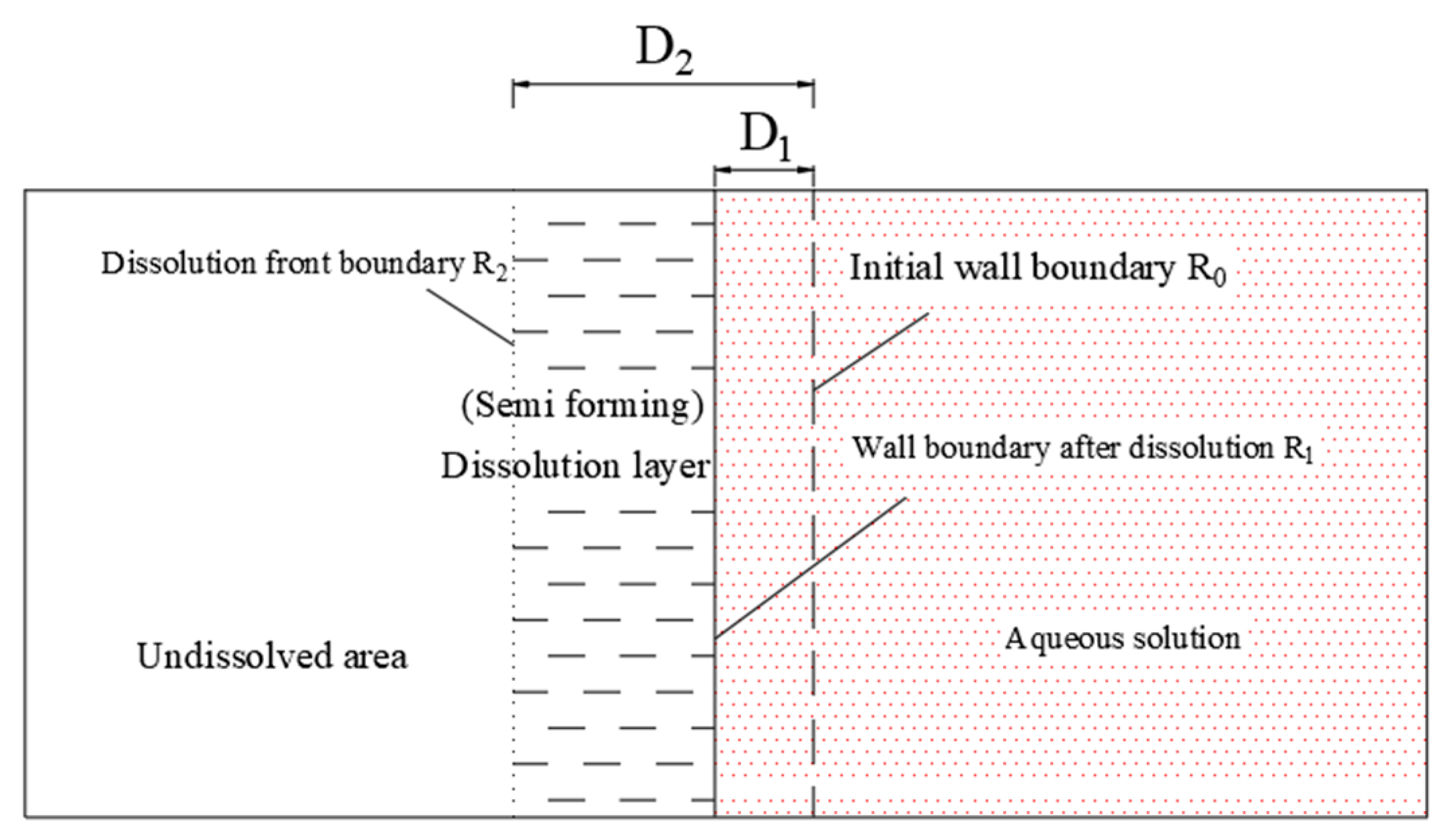
Based on the above research on macro and micro water solution characteristics and the laws and mechanisms of glauberite, a two-dimensional physical dissolution model of glauberite under hydrostatic conditions is established (Figure 24). The physical dissolution model has three boundaries: (1) Initial boundary R0: the initial wall surface of glauberite that is not subject to dissolution. After encountering the hydrostatic environment on this side, glauberite begins to dissolve and seep. (2) Post-dissolution boundary R1: after glauberite dissolution and seepage, the initial boundary is damaged due to particle peeling. Researchers [17,29] also found that a pore-scale model captures the coupling of dissolution and weakening-induced compaction. Stress suppresses permeability enhancement, with a stronger effect at higher stress. In this study, the visible outermost boundary is called boundary R1. There is only a small distance between R1 and R0 in the initial state of the water solution. At the initial moment of encountering water, the amount of dissolution produced by the specimen is quite small, so it can be assumed that R1 and R0 coincide in the initial state. R1 is a function related to time t, i.e., D1 = D1(t). D1 represents the distance that R1 advances compared with R0 at a certain moment of dissolution, that is, the dissolution footage. (3) Dissolution front R2: the interface between the dissolution layer and the non-dissolution area. R2 and R1 coincide in the initial state of dissolution. R2 is also a function related to time, i.e., D2 = D2(t). D2-D1 represents the thickness of the dissolution layer.
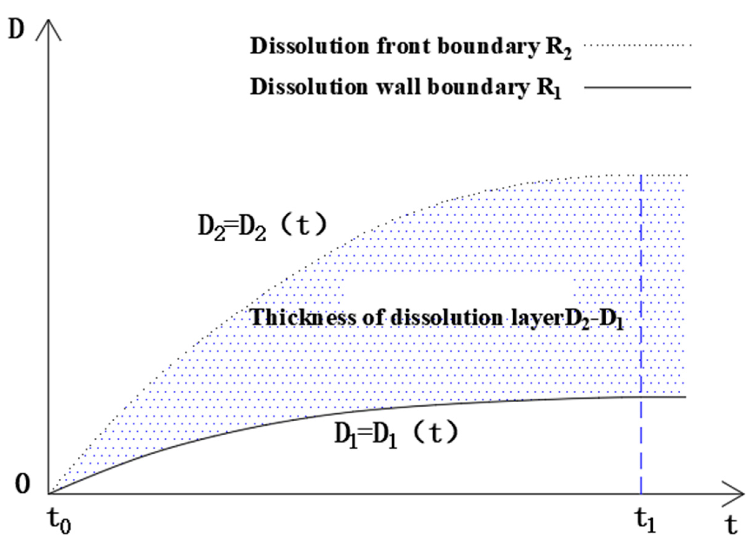
The D(t) relation in the dissolution process of mirabilite calcium can reflect the law of dissolution and penetration of mirabilite calcium under static water conditions (Figure 23). The D(t) relation refers to the change of dissolution penetration scale (D1) and dissolution layer thickness (D2-D1) with time t. Due to the direct measurement of the dissolved footage, there is some human error, but it does not affect the overall regular trend. Under the long-term static water solution environment, the dissolution rate of glauberite rock will gradually drop with the solution time, and the slope of the D(t) relationship curve will gradually decrease. D2 = D2(t) is a stepped rising curve (Figure 15); the curve in Figure 24 shows the fit of this stepped curve, which is brought about by the fact that the increase in solution concentration is necessarily brought about by the advance of the dissolution front R2 to the interior. The thickness of the dissolution layer gradually increases with the dissolution time, and the distance increment of D2 = D2(t) in unit time is significantly greater than that of D1 = D1(t). When the solution reaches saturation (t1), the dissolution and seepage of glauberite also stop, and the D(t) curve will maintain a horizontal after t1. At this time, the thickness of the dissolution layer reaches the maximum.

4.3. Impacts

Underground glauberite rock restricts the development of underground space. The dissolution of glauberite by groundwater produces caves and can cause potential harm to the pile foundation in the construction of urban underground space. Under the action of groundwater, the expansion of glauberite seriously affects the integrity of the formation and squeezes the subway. The waste residue and wastewater produced by underground space engineering are rich in sulfate ions, leading to higher corrosivity of groundwater and to the deterioration of groundwater quality. In this paper, a physical dissolution model has been established. The development scale of a glauberite karst cave is reasonably predicted based on the engineering geological conditions and the dissolution footage speed of glauberite rock. In the actual project of underground space development and utilization, large-scale solution caves may lead to geological problems such as uneven settlement, ground collapse, sudden gushing of water in foundation pits and chambers and corrosive groundwater. Therefore, in the development of underground space, if glauberite formation is found, sealing and drainage measures should be taken on time to prevent a reaction with water.

5. Conclusions

In this study, a continuous hydrostatic leaching test and a cyclic hydrostatic leaching test were carried out on glauberite rock taken from Chengdu, China. The dissolution characteristics and dissolution process mechanism of glauberite rock under hydrostatic conditions were studied. After 16 days of continuous hydrostatic leaching, the average mass loss rate of the specimen was 12.83%; after 16 cycles in cyclic leaching, the average mass loss rate of the specimen was 17.76%. In addition, the “differential dissolution” phenomenon of the glauberite rock specimens was more significant than that of the continuous hydrostatic leaching test, and tensile cracks and argillaceous fragments were produced. After 16 days of continuous hydrostatic leaching, the failure mode of the glauberite rock specimens changed from brittle failure before leaching to plastic failure; the average uniaxial compressive strength was 63% lower than that of the specimens in their natural state; the average elastic modulus was 76% lower than that of the specimens in their natural state; the average peak strain was 75% higher than that of the specimens in their natural state. The generation of a dissolution layer was the main reason for the strength deterioration of the glauberite rock specimens after leaching.
Na2SO4 in glauberite is dissolved under hydrostatic leaching, and the residual CaSO4 skeleton transforms into CaSO4•2H2O under hydration. The main reason for the mass loss of glauberite rock specimens after dissolution lies in the dissolution and loss of sodium sulfate in the dissolution layer. The phenomenon of “differential dissolution” and “unequal thickness dissolution” appears in the dissolution layer vertically. As the solution reaches saturation, it reaches the dynamic equilibrium state of dissolution and crystallization. The biggest difference between glauberite rock and other gypsum salts (e.g., salt rock and gypsum) after dissolution is the existence of the dissolution layer. For sodium chloride rock, the dissolution laws (such as dissolution rate and dissolution scale) can be mastered only by paying attention to its wall after dissolution, while for glauberite rock, the development law of the dissolution layer also requires understanding of the overall dissolution characteristics. The dissolution front is a hidden surface that cannot be directly observed from the outside, but it is an element that must not be ignored in engineering. At the same time, the dissolution layer thickness determined by the absolute distance between the dissolution front and the post-dissolution wall surface greatly affects the strength of the calcarenite.

Author Contributions

Conceptualization, S.C. and M.M.; methodology, S.C., M.M. and X.P.; experiment, D.S., X.Y., L.Q., Y.L. and M.Y.; writing—original draft preparation, S.C. and M.M.; writing—review and editing, S.C., M.M. and X.Y.; drawing the figures, M.M., D.S. and X.Y.; supervision, X.P.; funding acquisition, X.P. and S.C. All authors have read and agreed to the published version of the manuscript.

Funding

This study was supported by the National Natural Science Foundation of China (Grants No. 41931296, 41907254).

Informed Consent Statement

Not applicable.

Data Availability Statement

The datasets generated and/or analyzed during the current study are available in the [zenodo] repository, [https://zenodo.org/record/6891848#.YtzxgLZBxPY] (accessed on 9 October 2022).

Conflicts of Interest

The authors declare no conflict of interest.

References

  1. Spiers, C.J.; Lister, G.S.; Zwart, H.J. The influence of fluid-rock interaction on the rheology of salt rock and on ionic transport in the salt. In Technical Session on Rock Mechanics Advance in Laboratory Sample Testing; Commission European Communities: Luxembourg, 1984; pp. 268–280. [Google Scholar]
  2. Spiers, C.J.; Urai, J.L.; Lister, G.S. The effect of brine (inherent of added) on rheology and deformation mechanisms in salt rock. In The Mechanical Behavior of Salt; Conference Paper; Trans Tech publ: Clausthal-Zellerfeld, Germany, 1988; Volume 2, pp. 89–102. [Google Scholar]
  3. Peach, C.J.; Spiers, C.J. Influence of crystal plastic deformation on dilatancy and permeability development in synthetic salt rock. Tectonophysics 1996, 256, 101–128. [Google Scholar] [CrossRef]
  4. Kettel, D. The dynamics of gas flow through rock salt in the scope of time. In Norwegian Petroleum Society Special Publications; Elsevier: Amsterdam, The Netherlands, 1997; Volume 7, pp. 175–185. [Google Scholar]
  5. Lux, K.H.; Heusermann, S. Creep tests on rock salt with changing load as a basis for the verification of theoretical material laws. In Proceedings of the 6th International Symposium on Salt Symposium, Salt Institute, Portland, ME, USA, 12–14 October 1983; Volume 1, pp. 417–435. [Google Scholar]
  6. Senseny, P.E. Determination of a Constitutive Law for Salt at Elevated Temperature and Pressure; ASTM International: West Conshohocken, PA, USA, 1985; pp. 55–71. [Google Scholar]
  7. Cristescu, N.D. A general constitutive equation for transient and stationary creep of rock salt. Int. J. Rock Mech. Min. Sci. Geomech. Abstr. 1993, 30, 125–140. [Google Scholar] [CrossRef]
  8. Cristescu, N.D.; Paraschiv, I. Creep, damage and failure around large rectangular-like caverns and galleries. Mech. Cohesive Frict. Mater. Int. J. Exp. Model. Comput. Mater. Struct. 1996, 1, 165–197. [Google Scholar] [CrossRef]
  9. Hampel, A.; Hunsche, U.; Weidinger, P.; Blum, W. Description of the Creep of Rock Salt with the Composite Model-II. Steady-State Creep; Series on rock and soil mechanics; Trans Tech publ: Clausthal-Zellerfeld, Germany, 1998; pp. 287–299. [Google Scholar]
  10. Zhang, C.; Liang, W.; Li, Z.; Xu, S.; Zhao, Y. Observations of acoustic emission of three salt rocks under uniaxial compression. Int. J. Rock Mech. Min. Sci. 2015, 77, 19–26. [Google Scholar] [CrossRef]
  11. Jiang, T.; Shao, J.F.; Xu, W.Y.; Zhou, C.B. Experimental investigation and micromechanical analysis of damage and permeability variation in brittle rocks. Int. J. Rock Mech. Min. Sci. 2010, 47, 703–713. [Google Scholar] [CrossRef]
  12. Liang, W.G.; Zhao, Y.S.; Xu, S.G.; Dusseault, M.B. Effect of strain rate on the mechanical properties of salt rock. Int. J. Rock Mech. Min. Sci. 2011, 48, 161–167. [Google Scholar] [CrossRef]
  13. Yu, Y.M.; Liang, W.G.; Liu, J.S. Influence of solution concentration and temperature on the dissolution process and internal structure of glauberite. Int. J. Min. Met. Mater. 2018, 25, 1246–1255. [Google Scholar] [CrossRef]
  14. Petracchini, L.; Antonellini, M.; Billib, A.; Scrocca, D.; Trippetta, F.; Mollo, S. Pressure solution inhibition in a limestone-chert composite multilayer: Implications for the seismic cycle and fluid flow. Tectonophysics 2015, 646, 96–105. [Google Scholar] [CrossRef]
  15. Meer, S.D.; Spiers, C.J.; Peach, C.J. Kinetics of precipitation of gypsum and implication for pressure-solution creep. J. Geol. Soc. Lond. 2000, 157, 269–281. [Google Scholar] [CrossRef] [Green Version]
  16. Schenk, O.; Urai, J.L. Microstructural evolution and grain boundary structure during static rescystallization in synthetic polycrystals of sodium chloride containing saturated brine. Contrib. Miner. Petrol. 2004, 146, 671–682. [Google Scholar] [CrossRef]
  17. Roded, R.; Paredes, X.; Holtzman, R. Reactive transport under stress: Permeability evolution in deformable porous media. Earth Planet. Sci. Lett. 2018, 493, 198–207. [Google Scholar] [CrossRef]
  18. Urai, J.L.; Spiers, C.J.; Zwart, H.J.; Lister, G.S. Weakening of rock salt by water during long-term creep. Nature 1986, 324, 554–557. [Google Scholar] [CrossRef] [PubMed]
  19. Covington, M.D. Calcite Dissolution under Turbulent Flow Condit ions: A Remaining Conundrum. Acta Carsologica 2014, 43, 195–202. [Google Scholar] [CrossRef]
  20. Durie, R.W.; Jessen, F.W. The laminar boundary layer in the free convection dissolution of salt. In Proceedings of the Paper in the 2nd Symposium on Salt, Cleveland, OH, USA, May 1962. [Google Scholar]
  21. De Las Cuevas, C. Pore structure characterization in rock salt. Eng. Geol. 1997, 47, 17–30. [Google Scholar] [CrossRef]
  22. Liu, X.; Yang, X.; Wang, J.; Li, D.; Li, P.; Yang, Z. A dynamic dissolution model of rock salt under gravity for different flow rates. Arab. J. Geosci. 2016, 9, 226. [Google Scholar] [CrossRef]
  23. Liang, W.; Zhao, Y.; Xu, S.; Dusseault, M.B. Dissolution and seepage coupling effect on transport and mechanical properties of glauberite salt rock. Transp. Porous Media 2008, 74, 185–199. [Google Scholar] [CrossRef]
  24. Rong, K.; Wu, A.; Yin, S.; Li, H. Mineral CO2 Sequestration by Carbonation of Glauberite. IOP Conf. Ser. Earth Environ. Sci. 2019, 300, 032092. [Google Scholar] [CrossRef]
  25. Schulze, O. Investigations on damage and healing of rock salt. In The Mechanical Behavior of Salt–Understanding of THMC Processes in Salt; CRC Press: Boca Raton, FL, USA, 2017; pp. 33–43. [Google Scholar]
  26. Minkley, W.; Mühlbauer, J. Constitutive models to describe the mechanical behavior of salt rocks and the imbedded weakness planes. In The Mechanical Behavior of Salt–Understanding of THMC Processes in Salt; CRC Press: Boca Raton, FL, USA, 2017; pp. 119–127. [Google Scholar]
  27. Cui, S.; Pei, X.; Jiang, Y.; Wang, G.; Fan, X.; Yang, Q.; Huang, R. Liquefaction within a bedding fault: Understanding the initiation and movement of the Daguangbao landslide triggered by the 2008 Wenchuan Earthquake (Ms = 8.0). Eng. Geol. 2021, 295, 106455. [Google Scholar] [CrossRef]
  28. Hampel, A.; Schulze, O. The composite dilatancy model: A constitutive model for the mechanical behavior of rock salt. In The Mechanical Behavior of Salt–Understanding of THMC Processes in Salt; CRC Press: Boca Raton, FL, USA, 2017; pp. 99–107. [Google Scholar]
  29. Noiriel, C. Resolving time-dependent evolution of pore-scale structure, permeability and reactivity using X-ray microtomography. Rev. Mineral. Geochem. 2015, 80, 247–285. [Google Scholar] [CrossRef]
Figure 1. Glauberite obtained from drilling in underground space in Chengdu, China.
Sustainability 14 16739 g001
Figure 2. Test equipment.
Sustainability 14 16739 g002
Figure 3. Flow chart of continuous hydrostatic leaching test and cyclic hydrostatic leaching test.
Sustainability 14 16739 g003
Figure 4. Continuous hydrostatic leaching test of glauberite specimen #1.
Sustainability 14 16739 g004
Figure 5. Continuous hydrostatic leaching test of glauberite specimen #2.
Sustainability 14 16739 g005
Figure 6. Continuous hydrostatic leaching test of glauberite specimen #3.
Sustainability 14 16739 g006
Figure 7. Cyclic hydrostatic leaching test of glauberite specimen #4.
Sustainability 14 16739 g007
Figure 8. Cyclic hydrostatic leaching test of glauberite specimen #5.
Sustainability 14 16739 g008
Figure 9. Cyclic hydrostatic leaching test of glauberite specimen #6.
Sustainability 14 16739 g009
Figure 10. “Differential dissolution” phenomenon of glauberite after 16 cycles in cyclic leaching.
Sustainability 14 16739 g010
Figure 11. Changes in cyclic hydrostatic leaching mass of glauberite samples.
Sustainability 14 16739 g011
Figure 12. Fitting curve of mass change of glauberite specimen #5.
Sustainability 14 16739 g012
Figure 13. Crack development process of glauberite specimen #4 under cyclic hydrostatic solution.
Sustainability 14 16739 g013
Figure 14. Scanning characteristics of glauberite under electron microscope before and after solution.
Sustainability 14 16739 g014
Figure 15. XRD phase diagram before and after glauberite dissolution.
Sustainability 14 16739 g015
Figure 16. Solution concentration–time change curve.
Sustainability 14 16739 g016
Figure 17. The failure of glauberite samples before and 16 days after solution leaching.
Sustainability 14 16739 g017aSustainability 14 16739 g017b
Figure 18. Uniaxial compression test results of glauberite.
Sustainability 14 16739 g018
Figure 19. Comparison of section morphology before and after glauberite leaching.
Sustainability 14 16739 g019
Figure 20. Natural dried glauberite specimen.
Sustainability 14 16739 g020
Figure 21. A large amount of argillaceous debris peeled off when the specimen enters the water.
Sustainability 14 16739 g021
Figure 22. Conceptual diagram of longitudinal section of mirabilite specimen after still-water leaching.
Sustainability 14 16739 g022
Figure 23. Physical dissolution model of glauberite.
Sustainability 14 16739 g023
Figure 24. The variation of glauberite dissolution distance with time in hydrostatic environment.
Sustainability 14 16739 g024
Table 1. Test descriptions.
NumberTest NameSpecimenDescriptionEnvironment
1Continuous hydrostatic leaching test#1, #2, #3Leaching for 16 dWater PH = 7.2 temperature 24 °C (±0.2 °C), laboratory temperature 25.3 °C (±0.7 °C)
2Cyclic hydrostatic leaching test#4, #5, #6Soaking for 24 h + natural drying for 12 h in a dry–wet cycle, and 16 dry and wet cycles are carried out, with a total duration of 16 d
3Solution concentration monitoring test#1, #2, #3, #4, #5, #6Monitor the solution concentration with a hydrometer
4Uniaxial compression test#7, #8, #9Uniaxial compression test in natural state
5#10, #11, #12Uniaxial compression test after continuous hydrostatic immersion for 16 d
Note: Sample sizes are 5 cm (diameter) × 10 cm (height).
Publisher’s Note: MDPI stays neutral with regard to jurisdictional claims in published maps and institutional affiliations.