Article

The Face Stability Analysis of Shield Tunnels Subjected to Seepage Based on the Variational Principle

School of Civil Engineering, Changsha University of Science and Technology, Changsha 410004, China
*
Author to whom correspondence should be addressed.
Sustainability 2022, 14(24), 16538; https://doi.org/10.3390/su142416538
Submission received: 24 August 2022 / Revised: 20 November 2022 / Accepted: 23 November 2022 / Published: 9 December 2022
(This article belongs to the Topic Sustainable Built Environment)

Abstract

:
The stability of tunnel face remains a great challenge for tunnel engineers, especially when excavation is in a complex stratum under the water table. This paper aims to investigate the stability of soil in the front of a shield tunnel face induced by the presence of insufficient cabin pressure under the water table, on the basis of a variational principle and an upper bound theorem. The analytical expression of the rupture surface for the tunnel face is obtained, and the shapes of the rupture surface are plotted. Comparisons are made to check the present approach against the solution provided by numerical simulation techniques in order to show that the proposed method is valid. The parameter analysis indicates that the groundwater seepage has a significant effect on the range of the rupture surface for the shield tunnel face.

1. Introduction

The shield tunneling method has been developed as a main construction method for subway construction owing to its safety for excavation and its low disturbance to the surrounding environment. It is well known that stable soil in the front of the tunnel face, which is determined by the cabin pressure, is a key element in the constructive safety of a shield tunnel. The existing literature shows that insufficient cabin pressure will induce the collapse of the tunnel face, whereas overlarge cabin pressure will lead to soil uplift in the front of the tunnel face. When a shield tunnel is being drilled in a water-rich stratum, the underground water table will be disturbed by the excavation, which induces underground water seepage. However, numerous articles in the literature show that underground water seepage exerts a greatly adverse effect on the face stability. Moreover, the engineering accidents induced by instability of the tunnel face may result in serious casualties and property damage. Therefore, studying the stability of the tunnel face in shield tunnel excavation under the groundwater table is of primary significance.
Currently, numerous scholars have employed various methods to investigate the stability of the tunnel face. Because a limit analysis theorem can be used to effectively investigate the stability of the geotechnical engineering, many scholars have used this method to study this problem. Mollon et al. [1] established a three-dimensional (3D) multiblock rupture mechanism to study the collapse and the blow-out failure modes of a tunnel face by applying the upper bound method of limit analysis. Later, Mollon et al. [2] used a spatial discretization technique to establish a 3D rupture mechanism, and they derived a corresponding theoretical solution of the supporting force on the basis of the upper bound approach. By modifying the rupture mechanism proposed by Mollon et al. [2], Senent et al. [3] used this improved mechanism in conjunction with the Hoek–Brown yield criterion to study the stability of shield tunnels excavated in cracked rock. Moreover, Yang et al. [4] studied the influence of the inhomogeneity and anisotropy of soil on the ultimate supporting force of a shield tunnel that was excavated in an anisotropic stratum. Consequently, Xu et al. [5] proposed a new rotational failure mechanism and used this mechanism in conjunction with a nonlinear failure criterion to compute the theoretical solution of the cabin pressure for tunnel face. Later, Zhang et al. [6] constructed three-dimensional active and passive failure mechanisms of the tunnel face by investigating the failure features of rock mass in front of the tunnel face. On the basis of these mechanisms, Zhang et al. [6] obtained the safe range of supporting pressures of the shield tunnel face and validated the effectiveness of the computing results by applying this method in an actual project. To study the safety of a tunnel face when considering tensile strength cutoff, Chen et al. [7] proposed two improved failure mechanisms in the tunnel face. Using these new failure mechanisms, the limit supporting pressures of the tunnel face for collapse and blow-out modes are calculated and the calculating results are compared with the existing solutions.
Groundwater seepage is a one factor that affects tunnel stability when a tunnel is excavated under the water table. Thus, the study of the influence of seepage on the safety of a shield tunnel has drawn a great deal of attention, for some scholars. By improving on an existing model, Perazzelli et al. [8] employed the limit equilibrium theory to investigate the safety of the tunnel face under seepage flow conditions. To investigate the influence of pore pressure on the stability of soil in front of a tunnel face, Pan and Dias [9] calculated the distribution of pore pressure and obtained the theoretical solution for the cabin pressure of the tunnel face. Subsequently, using a modified three-dimensional failure mechanism as a base, Pan and Dias [10] studied the stability of soil in front of a tunnel face under the water table by employing an upper bound theorem of limit analysis. Later, finding that the study of the coupled flow deformation of a tunnel face is rare, Zou and Qian [11] developed a theoretical method to calculate the supporting pressure of a tunnel face for a shield tunnel drilled below the water table. Using the discretization technique as a base, Yang and Zhong [12] proposed a new active failure mechanism to investigate the stability of soil in front of a tunnel face when the tunnel is excavated below the water table. Using this mechanism, Yang and Zhong [12] calculated the supporting pressure of the tunnel while accounting for the pore pressure and validated the effectiveness of their method by comparing their results with the existing solutions. Finding that most of the existing studies have focused on the stability of tunnel faces excavated in saturated soil, Li et al. [13] proposed a method to study the stability of a tunnel face by accounting for the unsaturated seepage effect. Using this method, Li et al. [13] calculated the safety factor of the shield tunnel face and assessed the stability of a tunnel face drilled in saturated stratum. Using the computational fluid dynamics-discrete element method, Fu et al. [14] investigated the seepage effect on the rupture mode of the underwater tunnel face. Their achievements show that under seepage situations, the rupture region in the front of the tunnel face increases as the water depth increases. Weng et al. [15] designed a centrifuge test to study the rupture mode of tunnel faces caused by the lengthways slope angle of the tunnel and steady-state seepage. Their model test results present the progressive rupture mode of the excavation face caused by the two factors mentioned above.
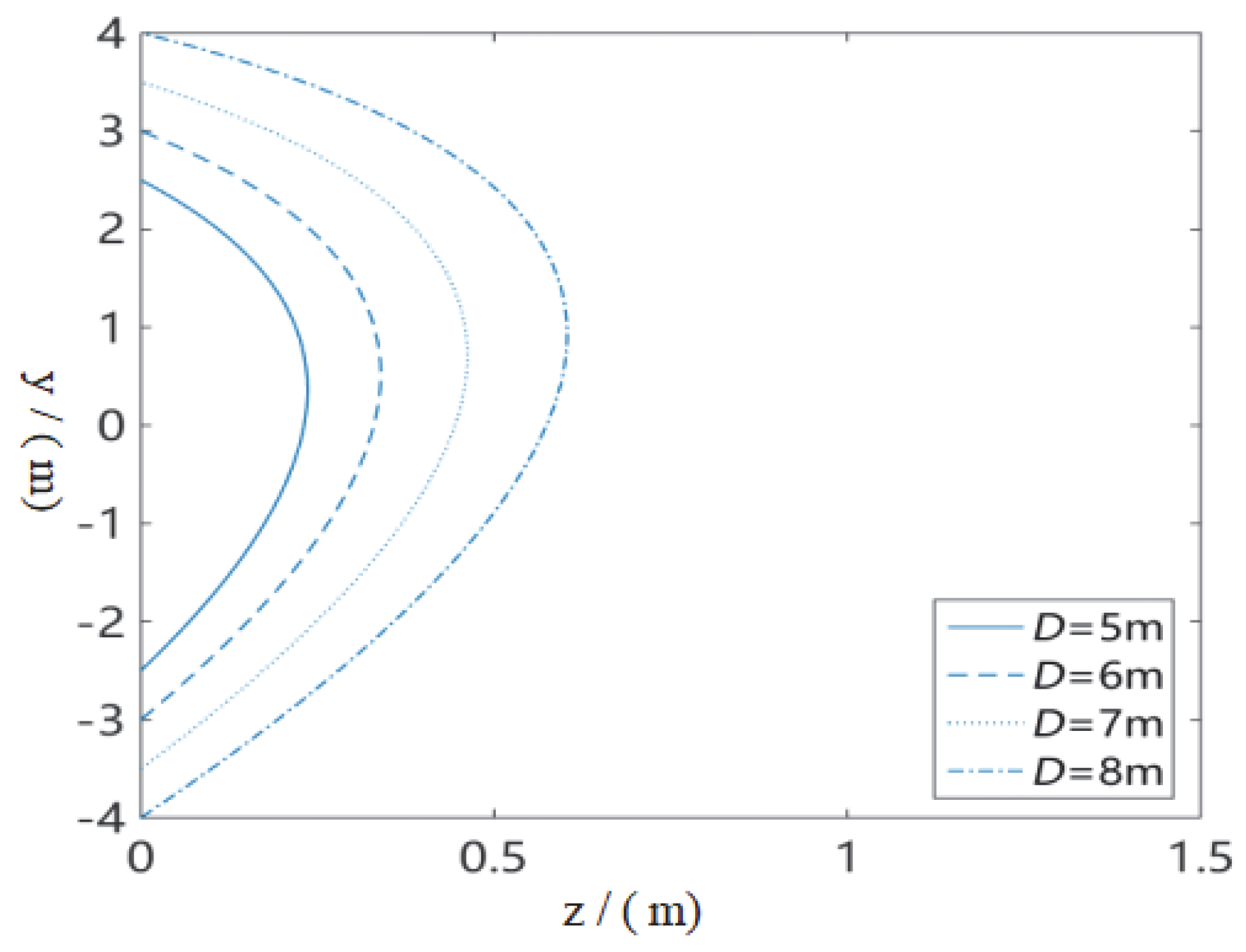
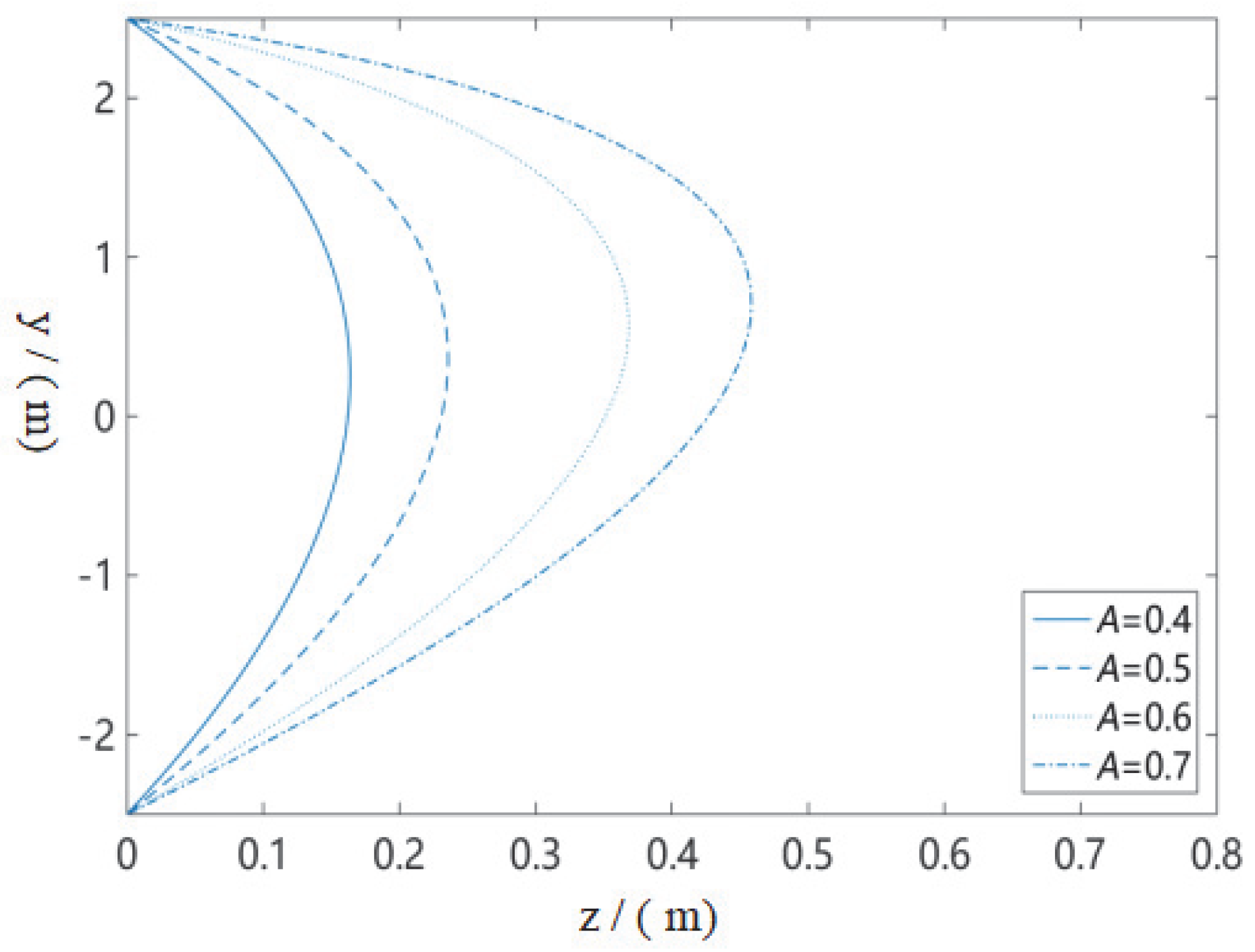
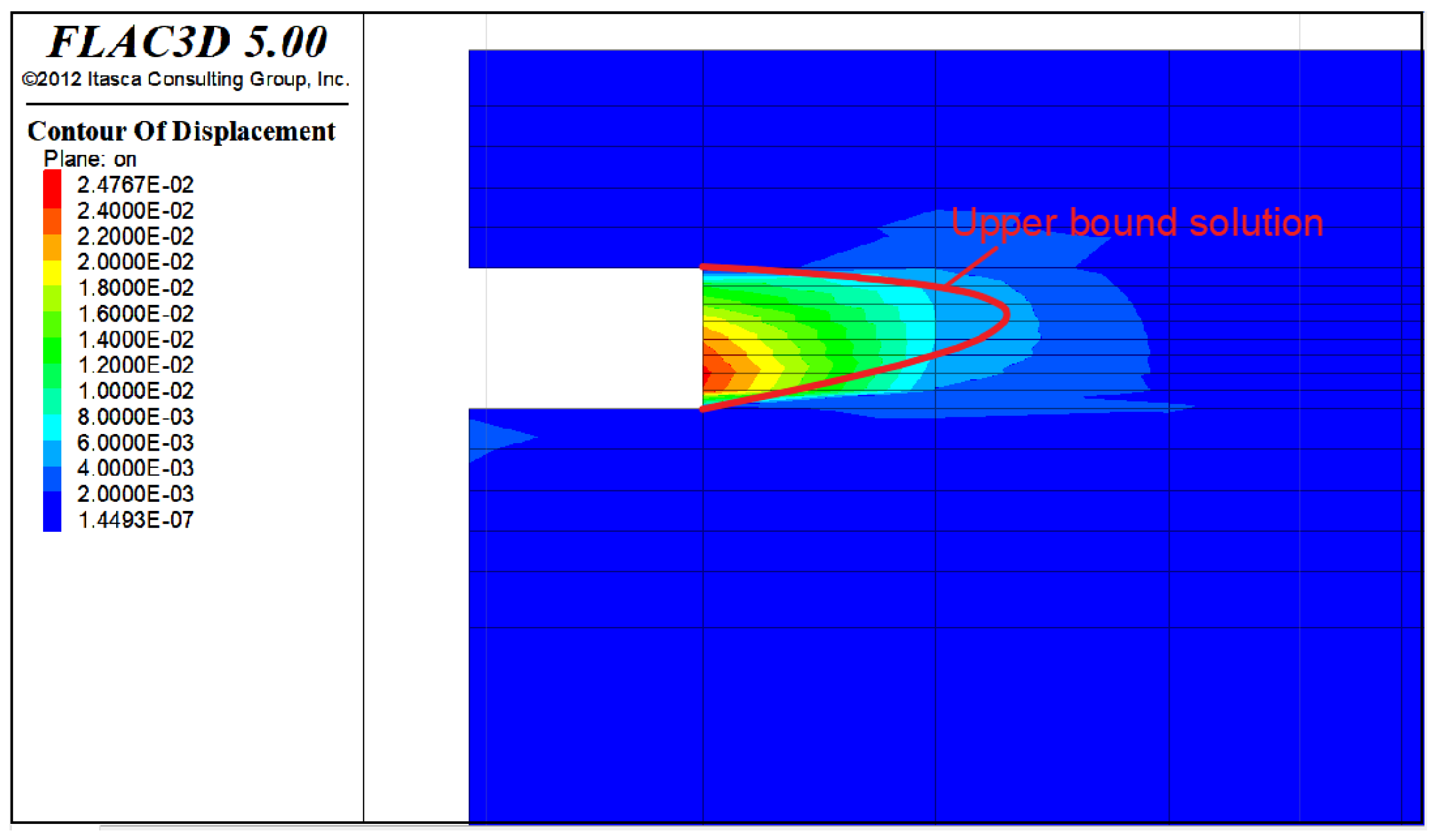
The purpose of our study is to investigate the groundwater seepage effect on shield tunnel face stability. To achieve this target, a new rupture mechanism that can be employed to describe the failure feature of tunnel face induced by insufficient cabin pressure under the water table is constructed. By regarding seepage force as an external force, the external rate of work produced by seepage force is introduced into the virtual equation, and the objective function of the rupture surface for the tunnel face is obtained. In the context of a variational principle, the equation of the rupture surface for the tunnel face at the limit state is derived, and likewise, the shapes of the rupture surface for various parameters are drawn. The proposed method is validated by comparing it with the results that have been provided by numerical simulation. The method can obtain the collapse region of the soil in the front of the tunnel face, which provides a useful reference for a stability assessment of a shield tunnel excavated under the water table.

2. Construction of a Failure Mechanism for a Tunnel Face, Accounting for Groundwater Seepage

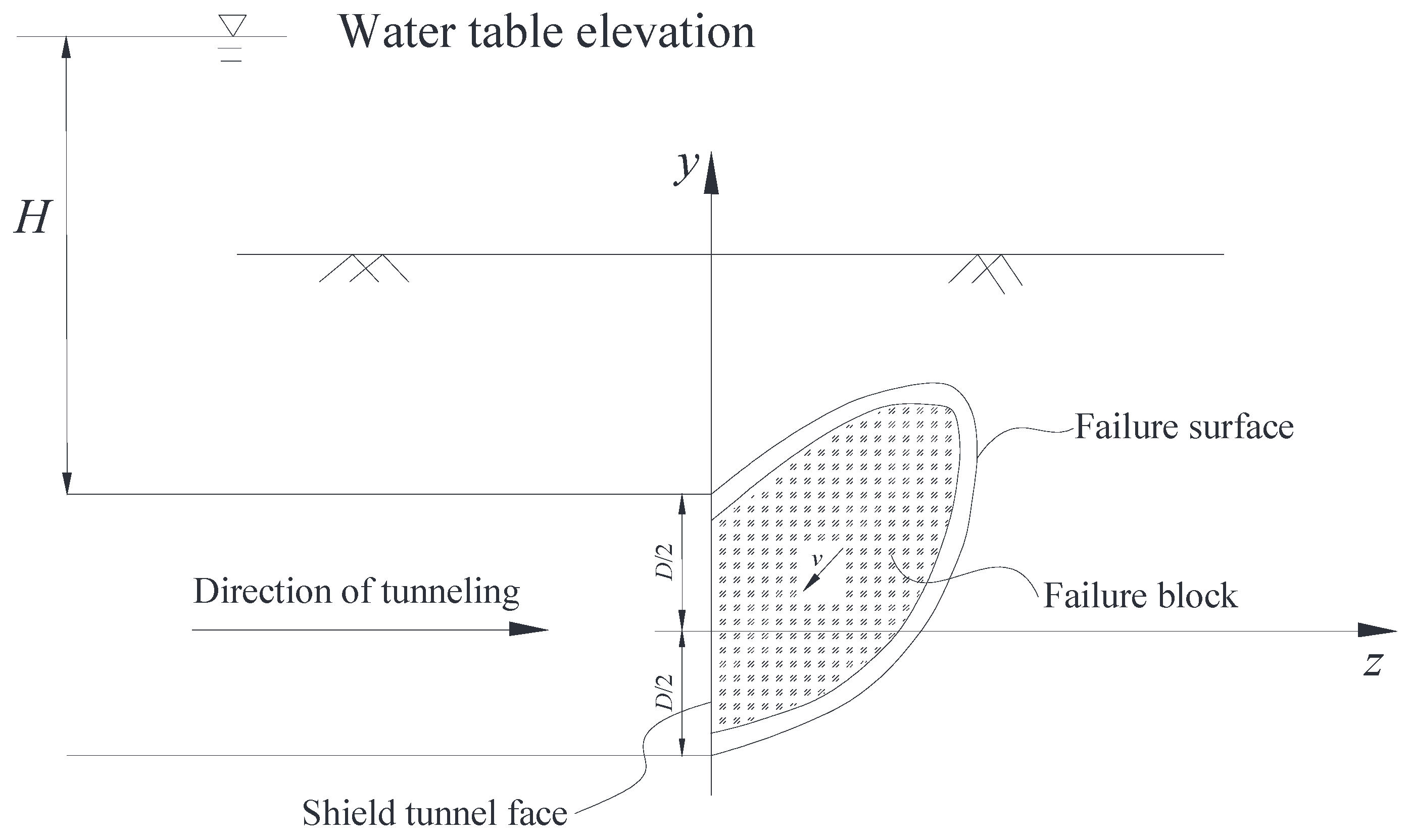
During the shield tunnel construction process, the pressure of the chamber of the shield machine is a key element in maintaining the stability of the tunnel face. The soil in front of the tunnel face may collapse when the soil chamber pressure is deficient to resist the earth pressure produced by the soil in front of the tunnel face. To describe the collapse characteristic of the tunnel face, an upper bound failure mechanism, which is composed of an arbitrary curve z ( y ) , is constructed, as shown in Figure 1 and Figure 2. Curve z ( y ) extends from the bottom to the top of the tunnel face, and a closed collapse surface forms in front of the tunnel face. The soil within the region of curve z ( y ) may collapse in the tunnel because of insufficient soil chamber pressure. Furthermore, D is the diameter of the shield tunnel, and L is the depth of the tunnel. H is the space from the groundwater head to the shield tunnel roof, and v is the velocity vector of the collapse block. It is assumed that the pressure of the chamber provided by the shield machine is σ T , which is evenly distributed over the entire excavation face. For calculation simplicity, some assumptions about the failure mechanism are presented, as follows:
  • The stratum around the tunnel is homogeneous soil, and the stratum is regarded as an ideal elastic-plastic body;
  • The collapse block is a rigid body, which means the deformation of the collapse block can be ignored.
Figure 1. Diagram of soil collapse damage in front of excavation.
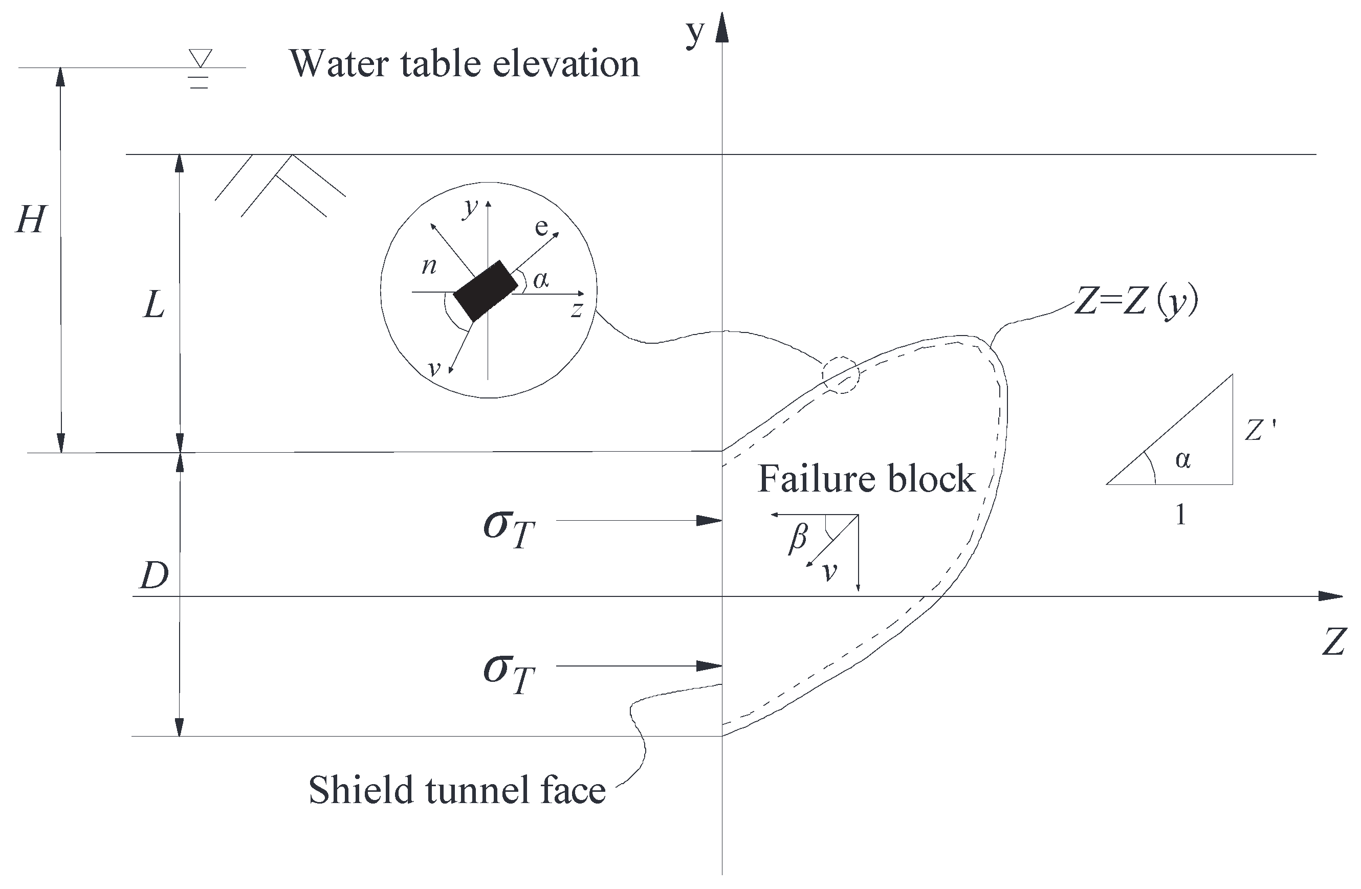
Sustainability 14 16538 g001
Figure 2. Mechanism of soil collapse damage in front of excavation in groundwater seepage.
Sustainability 14 16538 g002

3. Basic Principles

3.1. Upper Bound Theorem

The upper bound theory states that for any kinematically admissible velocity field, the internal energy dissipation power along the failure surface is not less than the power of the external loads. The equation of the virtual work equation can be expressed as follows:
V σ i j ε i j d V S T i v i d s + V X i v i d V
where σ i j and ε i j are the stress and strain rate in the upper bound velocity field, respectively; T i is an overload on the border; X i is the volume force; and v i is the velocity along the velocity discontinuity surface.

3.2. Hoek–Brown Yield Criteria

To study the failure features of the rock mass, the Hoek–Brown yield criteria is applied, which can be written as:
σ 1 = σ 3 + σ c i ( m b σ 3 σ c i + s ) a
where σ 1 , σ 3 , and σ c i are maximum main stress, minimum main stress, and the uniaxial compressive strength of the rock mass, respectively; m b , s , and a are material parameters that depend on geological indicators (GIs). The formula takes the following form:
m b = m i exp ( G S I 100 28 14 D )
s = exp ( G S I 100 9 3 D )
a = 1 2 + ( e G S I / 15 e 20 / 3 6 )  
where m i is a constant related to geotechnical properties and D is the disturbance factor. Because the internal dissipation rate of energy on the rupture surface is calculated by the normal and tangential stress strain, the Hoek–Brown yield criteria expressed by normal and shear stresses is used in this study, which can be written as:
τ = A σ c ( σ n σ t σ c ) B = E ( σ n σ t ) B
where σ n is the normal stress; τ is the shear stress; A and B are material constants; and σ c and σ t represent the uniaxial compressive strength and the tensile strength of the rock mass, respectively.

3.3. The Analysis of Seepage Field

The influence of groundwater on the stability of geotechnical structures represents the interaction of pore water between soil particles. Moreover, the formation of the pore water pressure is related to the permeability of the soil. Therefore, when studying the stability of geotechnical structures in the seepage field, the effect of seepage must be taken into account. Because the seepage force is a volume force that acts on every point of the soil in the seepage field, calculating the seepage force is difficult. In the two-dimensional seepage model, the drag force of seepage water on soil particles in a unit area can be calculated by using the following formula:
f z = γ w h z , f y = γ w h y
where h is the total hydraulic head and γ w is the water unit weight. By applying the Gauss integral theory to the surface integral of seepage force along the rupture block in front of the tunnel face, the expressions for the horizontal and vertical components of the seepage force acting along the rupture block can be obtained:
F z ( β ) = γ w ( sin β S 1 h * d s + S 2 h * d s )
F y ( β ) = γ w ( cos β S 1 h * d s + S 2 h * d s )
where S 1 is the sliding surface, S 2 is the tunnel face, and β is the angle between the sliding block and the horizontal plane. h * is the average water head on the horizontal direction of the sliding block, which can be calculated by using the following formula:
h * = 1 D h ( z , y ) d y
By combining Equations (8)–(10), the horizontal and vertical components of the seepage force can be expressed as:
F z ( β ) = γ w ( sin β S 1 h * d s + S 2 h * d s )                         = γ w y 0 y 0 [ sin β ( H + D 2 ) 1 + z 2 + ( H + D 2 ) ] d y
F y ( β ) = γ w ( cos β S 1 h * d s S 2 h * d s )                     = γ w y 0 y 0 [ cos β ( H + D 2 ) 1 + z 2 + ( H + D 2 ) ] d y
where D is the tunnel excavation diameter and H is the space between the groundwater level and the tunnel roof.

4. Upper Bound Solution for the Collapse Surface for a Tunnel Face, Accounting for Groundwater Seepage

As Chen [16] pointed out, the equation of virtual work in the kinematically admissible velocity field comprises the external rate of work and the internal rate of dissipation. Moreover, the external rate of work is produced by the external force of the presented failure mechanism, which includes the soil gravity, the pressure of the chamber, and the seepage force. Thus, the external rate of work generated by the external force can be calculated. The rate of work done by soil gravity can be obtained by applying it to the entire failure surface.
W G · = y 0 y 0 γ z v sin β d y
where γ is the bulk density of rock/soil. Because the pressure of chamber σ T is evenly distributed over the entire tunnel face, the rate of work produced by the pressure of the chamber can be expressed by:
W C · = y 0 y 0 σ T cos β v d y
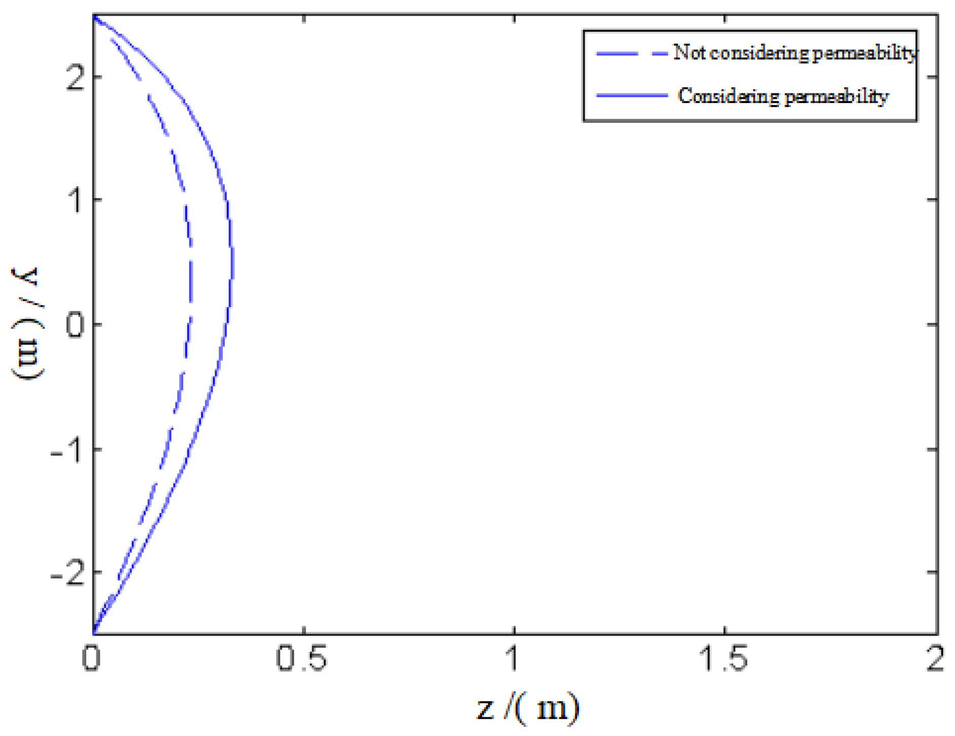
As mentioned above, the effect of seepage is a significant factor that should be taken into account in tunnel face stability analysis. Thus, using the expressions of horizontal and vertical components of the seepage force, an expression for the rate of work produced by seepage force can be written as:
W W · = y 0 y 0 ( F z cos β + F y sin β ) v d y = y 0 y 0 γ w ( H + D 2 ) ( sin β cos β ) d y
On the other hand, the computation of the dissipation rate in the presented rupture mechanism is more complex than the calculation of the external rate of work. The soil is assumed to obey an associated flow law. When the potential surface is in accordance with the yield surface, the potential function is:
G = τ E ( σ n σ t ) B
Moreover, when the plastic flow occurs in the collapse surface, the strain increment can be expressed as:
{ ( ε n · ) i = λ G σ n = λ E B ( σ n σ t ) B 1 ( γ n · ) i = G σ n = λ
where λ is the plasticity multiplier. As mentioned above, any random point on the collapse surface will obey the principle of small deformation, and the rate of deformation for the point is approximately equal to the rate of strain. Given the geometric relationships illustrated in Figure 3, the strain increment of any point on the collapse surface is:
{ ( ε n · ) i = v sin ( α i β ) t ( γ n · ) i = v cos ( α i β ) t
where α i is the angle between the tangent vector and the z-axis at any point on the collapse surface. Moreover, tan α i = z ( y ) , where t is the thickness of the plastic flow zone.
By combining Equations (16) and (17), the following equation can be obtained:
λ = v t cos ( α i β )
{ τ i = E [ E B cot ( α i β ) ] B 1 B σ i = σ t + [ E B cot ( α i β ) ] 1 1 B
Because the energy dissipation occurs only at the velocity discontinuity surfaces, the rate of energy dissipation for any point on the velocity discontinuity surfaces can be calculated only by superimposing the rate of energy dissipation on the normal direction and the tangential direction. Thus, the rate of energy dissipation for any point on the rupture surface is:
Δ D i · = σ i ε i · + τ i γ i ·                 = v sin ( α i β ) t { σ t + cot ( α i β ) 1 1 B [ ( E B ) 1 1 B E ( E B ) B 1 B ] }
For mathematical simplicity, the following equation is introduced:
E ¯ = ( E B ) 1 1 B E ( E B ) B 1 B
Merging part of Equation (21) with part of Equation (20), the rate of energy dissipation for any point on the collapse surface is:
Δ D i · = v sin ( α i β ) t [ σ t + E ¯ cot ( α i β ) 1 1 B ]
On the basis of the geometrical relation illustrated in Figure 2 and trigonometric function, the following equations are determined.
sin ( α i β ) = z cos β sin β 1 + z 2 , cot ( α i β ) = 1 + z tan β z tan β
By applying Equation (22) to the entire collapse surface and combining Equation (23), the total rate of energy dissipation along the collapse surface is:
W D = y 0 y 0 v ( z cos β sin β ) d 1 + z 2 [ σ t + E ¯ ( 1 + z tan β z tan β ) 1 1 B ] d s               = y 0 y 0 ( z cos β sin β ) [ σ t + E ¯ ( 1 + z tan β z tan β ) 1 1 B ] v d y
On the basis of the kinematical approach, the relationship between the rate of external work and the rate of energy dissipation is obtained:
W G + · W C · + W W · W D
The aim of this study is to investigate the failure mode and failure range of the soil in the front of the tunnel face at limit state. To obtain the analytical equations of the rupture surface at the limit state, it is necessary to establish a target function that includes the equation of the failure surface, by using the external rate of work and the rate of the energy dissipation. By incorporating Equations (12)–(14) and (24) into Equation (25), the target function is determined:
J = W D ( W G · + W C · + W W · )       = y 0 y 0 ( z cos β sin β ) [ σ t + E ¯ ( 1 + z tan β z tan β ) 1 1 B ] γ z sin β + σ T cos β       γ w ( H + D 2 ) ( sin β cos β ) v d y
Because independent variable z in Equation (26) is a function, objective function J can be regarded as a functional, which can be expressed as:
J = y 0 y 0 F [ y , z ( y ) , z ( y ) ] d y
where
F [ y , z , z ] = ( z cos β sin β ) [ σ t + E ¯ ( 1 + z tan β z tan β ) 1 1 B ] γ z sin β + σ T cos β γ w ( H + D 2 ) ( sin β cos β )
However, the upper bound solution, which derives from the relation between the external rate of work and the rate of the energy dissipation, is not the real result. According to Chen [16], the real result of the rupture surface can be obtained only when objective function J has reached its extreme value. Furthermore, Equation (28) is a special case of the Euler equation, which means that the extreme solution of the functional can be converted into solving the solution of Equation (28) under fixed boundary conditions. Thus, the first incorporation of Equation (28) is:
F z F z = c 1
where
F z = σ t cos β + E ¯ cos β ( 1 + z tan β z tan β ) 1 1 B E ¯ ( 1 B ) cos β ( 1 + z tan β ) B 1 B ( z tan β ) 1 1 B
After some simplification, the following equation is derived:
E ¯ ( 1 + z tan β z tan β ) 1 1 B [ sin β + z ( 1 B ) ( 1 + z tan β ) cos β ] σ t sin β γ z sin β + σ T cos β γ w ( H + D 2 ) ( sin β cos β ) = c 1
On the basis of Equation (31), the expression of z 
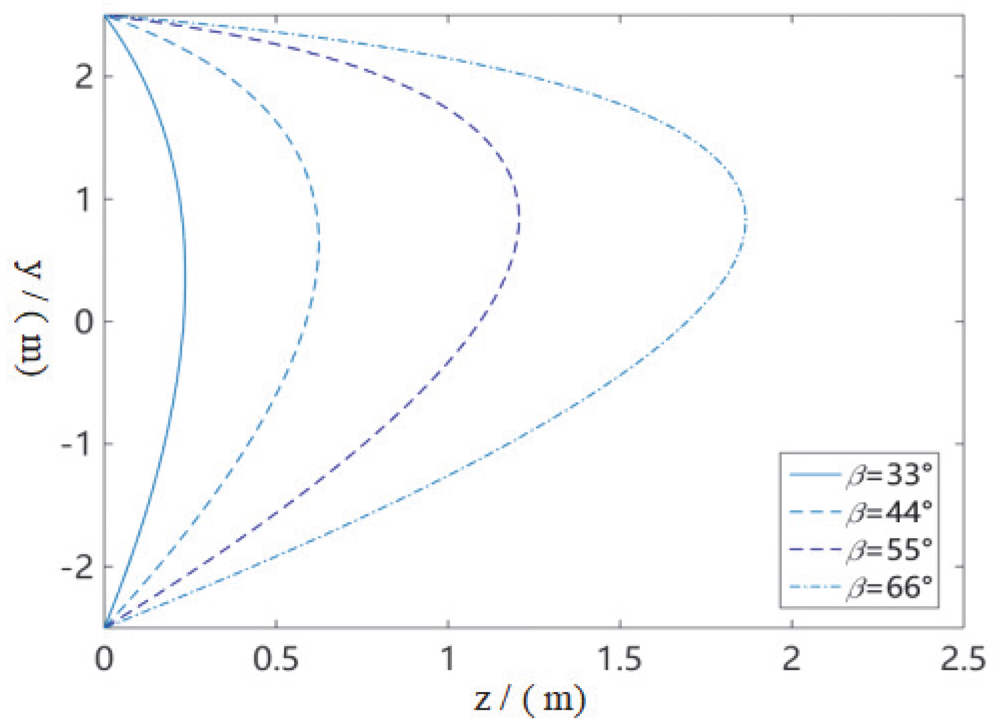
is obtained. After calculating the incorporated expressions, a set of curves that reaches extreme solutions is derived:
y = d z φ ( z , c 1 ) + c 2
where c 1 and c 2 are integration constants. Using geometric boundary conditions z ( D 2 ) = z ( D 2 ) = 0 , the values of c 1 and c 2 can be determined.
The value of parameter B is extremely important for solving Equation (31). According to Hoek and Brown [17], the value of parameter B ranges from 0 to 1. However, Equation (31) is a linear differential equation only when B = 0.5 , which can be solved analytically. When B 0.5 , Equation (31) is a complex nonlinear partial differential equation, which cannot be solved analytically. Therefore, in this study, the equation for a collapse surface of a tunnel face at limit state is discussed only for the parameter B = 0.5. When parameter B = 0.5 , Equation (31) can be simplified as:
E ¯ ( 1 + z tan β z tan β ) 2 [ sin β + 2 z ( 1 + z tan β ) cos β ] σ t sin β γ z sin β + σ T cos β γ w ( H + D 2 ) ( sin β cos β ) = c 1
A MATLAB [18] program is employed to solve this nonlinear partial differential equation. Firstly, a form of Equation (33), which is expressed by separating variables z and y, can be obtained by using a simplified calculation. Then, by substituting fixed boundary conditions, the values of integration constants c 1 and c 2 are determined. Finally, a particular solution among these solutions that satisfies boundary condition { D 2 y D 2 , z > 0 } is found. In summary, the equation for the collapse surface of the soil in front of the shield tunnel face is obtained:
z ( y ) = { 1 6 E ¯ 16 cos 2 β + 16 2 sin 2 β { E ¯ [ 2 E ¯ + 2 E ¯ cos 4 β + ( cos 2 β cos 4 β )                   ( 2 σ t + D γ w + 2 H γ w ) + 2 c 1 cos 2 β sin β + cos 3 β sin β ( 2 c 2 γ 2 σ T D γ w                   2 H γ w 2 γ y ) + cos β sin β ( 2 γ y 2 c 2 γ ) ] } 1 2 + ( c 2 γ γ y )                   ( 3 cos 3 β sin β + sin 3 β cos β cos 3 β sin 3 β cos β sin β ) } / [ γ ( cos 3 β                   cos β ) 2 ]

5. Effect of Various Parameters on the Shape of a Collapse Surface of a Tunnel Face

To study the effect of different parameters on the collapse range of the soil in the front of the shield tunnel face, while accounting for groundwater seepage, the shapes of the collapse surface for the soil in front of the shield tunnel face are plotted based on Equation (34), with various parameters. These parameters, which are used in the parametric analysis, are presented as follows: γ = 7.5 kN/m3, L = 10 m, H = 10 m, σT = 18 kN, σt = 0, σc = 10~100 kPa, A = 0.4~0.7, and β = 33~66°. Moreover, the shapes of the collapse surface for the soil in the front of the shield tunnel face that correspond to the abovementioned parameters are plotted in Figure 3, Figure 4, Figure 5, Figure 6 and Figure 7.
According to Figure 3, Figure 4, Figure 5, Figure 6 and Figure 7, the ranges of the collapse surface increase with the increase of parameters D, A, and β. Furthermore, the ranges of the collapse surface decrease with the increase of parameter σc when other parameters are fixed.
To investigate the effect of underground water seepage on the collapse region of the soil in the front of the shield tunnel face, the shapes of the rupture surface while accounting for seepage and while not accounting for seepage are drawn in Figure 7. According to Figure 7, the collapse range under the consideration of seepage effect is about 0.2 m larger than the collapse range that doesn’t account for seepage when other parameters are the same. Consequently, the effect of groundwater seepage on the stability of the soil in front of shield tunnel face cannot be ignored when a shield tunnel is excavated in a groundwater-rich stratum.

6. Comparison with Numerical Simulation Result

6.1. Numerical Model of Shield Tunnel That Accounts for Groundwater Seepage

To verify the validity of the theoretical result presented in this study, the theoretical result is compared with the numerical solution provided by the numerical simulation technique. A three-dimensional numerical model of a shield tunnel excavated under the groundwater table is constructed with software FLAC3D [19]. The diameter of the tunnel D is 6 m, the distance between the ground surface and the tunnel roof is 9 m, and the groundwater table measured from the tunnel roof is also 9 m. The size of the 3D numerical model is 100 m, 50 m, and 69.4 m in the transversal, longitudinal, and vertical directions, respectively. The thickness of the tunnel lining is 0.3 m. Because the accuracy of the meshing grid has a significant influence on the numerical calculation results, an inhomogeneous grid is employed in the constructed model, which can be seen in Figure 8. To make the comparison under the same conditions, the rock mass is assumed as homogeneous.
Because the rate of the energy dissipation of the collapse surface is computed by superimposing the rate of energy dissipation on the normal direction and the tangential direction, the H–B yield criteria expressed by normal and shear stresses is used in this study. However, the H–B yield criteria embedded in the FLAC3D [19] program is represented by the major and minor main stresses. Thus, to make the comparison under the same circumstances, the parameters of H–B criteria in the two forms should be equivalently converted. Using the method proposed by Hoek and Brown [16], the parameters of the H–B failure criterion listed in Table 1 are equivalently converted into the parameters of the H–B failure criterion listed in Table 2.

6.2. Comparison Analysis between Numerical Solution and Upper-Limit Solution

Using the parameters listed in Table 2 and the numerical model mentioned above, the contours of the displacement for the tunnel face that reflect the shape of a collapse surface are obtained, which can be seen in Figure 9. The collapse surface constituted by the boundary of the displacement is in accordance with the rupture surface derived from the theoretical analysis. Furthermore, the upper bound solution of the collapse surface obtained from Equation (34) and Table 1 is superimposed in Figure 9. According to this figure, the theoretical result of the collapse surface is similar to the collapse surface obtained from the numerical simulation. The similarity between the two methods for the tunnel collapse surface indicates that the theoretical methods proposed in this study are valid.

7. Conclusions

This paper aimed to study the rupture mode of a shield tunnel caused by insufficient cabin pressure under the water table. A new collapse mechanism, which is composed of an arbitrary curve, was constructed to illustrate the collapse characteristic of the soil in the front of the tunnel face. Using this mechanism, an analytical expression of the collapse surface of a shield tunnel face was obtained, according to a kinematical approach while accounting for the effect of seepage. By comparing it with the numerical solution of collapse failure surface obtained from the numerical simulation technique, the validity of the proposed theoretical method was verified. Using the equation of the collapse surface for a shield tunnel face, the shapes of the rupture surface were drawn for various parameters. The parameter analysis indicated that the groundwater seepage had a significant effect on the range of the rupture surface for the shield tunnel face. The range of the collapse surface increased when the groundwater seepage was factored in. Moreover, the region of the rupture surface increased with the increases in parameters D, A, and β and decreased with the increase in σc. If a shield tunnel is excavated in groundwater-rich strata, the effect of groundwater seepage on the stability of the tunnel face cannot be ignored.

Author Contributions

Conceptualization, F.H.; Formal analysis, Z.Z. and F.H.; Data curation, M.Z.; Writing—original draft, Z.Z.; Project administration, Z.Z.; Funding acquisition, T.L. All authors have read and agreed to the published version of the manuscript.

Funding

This study was supported by the National Natural Science Foundation of China (Grants 51878074, 52278395 and 52078061) and the Natural Science Foundation of Hunan Province, China (Grant No. 2021JJ30714). Their financial support is greatly appreciated.

Data Availability Statement

The data presented in this study are available on request from the corresponding author.

Conflicts of Interest

The authors declare no conflict of interest.

References

  1. Mollon, G.; Dias, D.; Soubra, A.H. Probabilistic analysis and design of circular tunnels against face stability. Int. J. Geomech. 2009, 9, 237–249. [Google Scholar] [CrossRef] [Green Version]
  2. Mollon, G.; Dias, D.; Soubra, A.H. Rotational failure mechanisms for the face stability analysis of tunnels driven by a pressurized shield. Int. J. Numer. Anal. Methods Geomech. 2011, 35, 1363–1388. [Google Scholar] [CrossRef] [Green Version]
  3. Senent, S.; Mollon, G.; Jimenez, R. Tunnel face stability in heavily fractured rock masses that follow the Hoek-Brown failure criterion. Int. J. Rock Mech. Min. Sci. 2013, 60, 440–451. [Google Scholar] [CrossRef]
  4. Yang, X.L.; Li, W.T.; Pan, Q.J. Influences of anisotropy and inhomogeneity on supporting pressure of tunnel face with kinematical approach. J. Cent. South Univ. 2015, 22, 3536–3543. [Google Scholar] [CrossRef]
  5. Xu, J.S.; Du, D.C.; Yang, Z.H. Upper bound analysis for deep tunnel face with joined failure mechanism of translation and rotation. J. Cent. South Univ. 2015, 22, 4310–4317. [Google Scholar] [CrossRef]
  6. Zhang, J.H.; Wang, W.J.; Zhang, D.B.; Zhang, B.; Meng, F. Safe range of retaining pressure for three-dimensional face of pressurized tunnels based on limit analysis and reliability method. KSCE J. Civ. Eng. 2018, 22, 2625–2656. [Google Scholar] [CrossRef]
  7. Chen, G.H.; Zou, J.F.; Liu, S.X. Stability Analysis of Pressurized 3D Tunnel Face with Tensile Strength Cutoff. Int. J. Geomech. 2021, 21, 04021226. [Google Scholar] [CrossRef]
  8. Perazzelli, P.; Leone, T.; Anagnostou, G. Tunnel face stability under seepage flow conditions. Tunn. Undergr. Sp. Tech. 2014, 43, 459–469. [Google Scholar] [CrossRef]
  9. Pan, Q.J.; Dias, D. The effect of pore water pressure on tunnel face stability. Int. J. Numer. Anal. Methods Geomech. 2016, 40, 2123–2136. [Google Scholar] [CrossRef]
  10. Pan, Q.J.; Dias, D. Three-dimensional face stability of a tunnel in weak rock masses subjected to seepage forces. Tunn. Undergr. Sp. Tech. 2018, 71, 555–566. [Google Scholar] [CrossRef]
  11. Zou, J.F.; Qian, Z.H. Face-stability analysis of tunnels excavated below groundwater considering coupled flow deformation. Int. J. Geomech. 2018, 18, 04018089. [Google Scholar] [CrossRef]
  12. Yang, X.L.; Zhong, J.H. Stability analysis of tunnel face in nonlinear soil under seepage flow. KSCE J. Civ. Eng. 2019, 23, 4553–4563. [Google Scholar] [CrossRef]
  13. Li, Z.W.; Yang, X.L.; Li, T.Z. Face stability analysis of tunnels under steady unsaturated seepage conditions. Tunn. Undergr. Sp. Tech. 2019, 93, 103095. [Google Scholar] [CrossRef]
  14. Fu, Y.B.; Zeng, D.Q.; Xiong, H.; Li, X.H.; Chen, Y.L. Seepage effect on failure mechanisms of the underwater tunnel face viaCFD–DEM coupling. Tunn. Undergr. Sp. Tech. 2022, 146, 104591. [Google Scholar]
  15. Weng, X.L.; Sun, Y.F.; Yan, B.H.; Niu, H.S.; Lin, R.G.; Zhou, S.Q. Centrifuge testing and numerical modeling of tunnel face stability considering longitudinal slope angle and steady state seepage in soft clay. Tunn. Undergr. Sp. Tech. 2020, 101, 103406. [Google Scholar] [CrossRef]
  16. Chen, W.F. Limit Analysis and Soil Plasticity; Elsevier Science: Amsterdam, The Netherlands, 1975. [Google Scholar]
  17. Hoek, E.; Brown, E.T. Practical estimate of rock mass strength. Int. J. Rock Mech. Min. Sci. 1997, 34, 1165–1186. [Google Scholar] [CrossRef]
  18. MATLAB 9.1; Computer Software. MathWorks Inc.: Natick, MA, USA, 2016.
  19. FLAC3D; Computer Software. Itasca Consulting Group: Minneapolis, MN, USA, 2012.
Figure 3. Collapse surface of a tunnel face for different values of D .
Sustainability 14 16538 g003
Figure 4. Collapse surface of a tunnel face for different values of A .
Sustainability 14 16538 g004
Figure 5. Collapse surface of a tunnel face for different values of σ c .
Sustainability 14 16538 g005
Figure 6. Collapse surface of a tunnel face for different values of β .
Sustainability 14 16538 g006
Figure 7. Effect of groundwater seepage on the collapse surface of a tunnel face.
Sustainability 14 16538 g007
Figure 8. 3D model of shield tunnel excavated under the water table.
Sustainability 14 16538 g008
Figure 9. Comparison of a collapse surface between a theoretical solution and a numerical solution.
Sustainability 14 16538 g009
Table 1. Hoek–Brown parameters represented by normal and shear stresses.
Weight
kN/m3
Elastic Modulus
G / MPa
Poisson’s Ratio
μ
Uniaxial Compressive
Strength
σ c i / kPa
Uniaxial
Tensile Strength
σ t m / kPa
Hoek–Brown Parameter
A
Hoek–Brown
Parameter
B
18800.31500.50.25050.5
Table 2. Hoek–Brown parameters represented by major and minor principal stresses.
Weight
kN/m3
Elastic Modulus
G / MPa
Poisson’s Ratio
μ
Uniaxial Compressive
Strength
σ c i / kPa
Hoek–Brown Parameter
a
Hoek–Brown
Parameter
m b
Hoek–Brown
Parameter
s
18800.31500.50.31550.0622
Publisher’s Note: MDPI stays neutral with regard to jurisdictional claims in published maps and institutional affiliations.

