Article

Life Cycle Assessment of Advanced Building Components towards NZEBs

1
IRES—Innovation in Research & Engineering Solutions, Rue Koningin Astridlaan 59B, 1780 Wemmel, Belgium
2
Faculty of Civil Engineering, Institute of Concrete Construction, Leipzig University of Applied Sciences (HTWK Leipzig), PF 30 11 66, 04251 Leipzig, Germany
3
RISE—Research Institutes of Sweden, Brinellgatan 4, 50115 Borås, Sweden
4
INEGI—Institute of Science and Innovation in Mechanical and Industrial Engineering, Campus da FEUP, R. Dr. Roberto Frias 400, 4200-465 Porto, Portugal
5
LAETA—Associated Laboratory of Energy, Transports and Aeronautics, Campus da FEUP, R. Dr. Roberto Frias 400, 4200-465 Porto, Portugal
*
Author to whom correspondence should be addressed.
Sustainability 2022, 14(23), 16218; https://doi.org/10.3390/su142316218
Submission received: 19 September 2022 / Revised: 27 October 2022 / Accepted: 25 November 2022 / Published: 5 December 2022
(This article belongs to the Special Issue Life Cycle Thinking and Sustainability Assessment of Buildings)

Abstract

:
The building sector accounts for 40% of the total energy consumed in Europe at annual basis, together with the relevant Greenhouse Gas (GHG) emissions. In order to mitigate these impacts, the concept and establishment of the Nearly Zero Energy Buildings (NZEBs) is under continuous and intensive research. In fact, as the energy used for buildings’ operation becomes more efficient, impacts resulting from the buildings’ embodied energy become of more importance. Therefore, the selection of building materials and components is of high significance, as these affect the energy performance and potential environmental impacts of the building envelopes. The objective of this study is to perform a preliminary Life Cycle Assessment (LCA) on advanced multifunctional building components, aiming to achieve lower embodied emissions in NZEBs. The advanced components analyzed are composite panels for facade elements of building envelopes, providing thermal efficiency. The design of sustainable building envelope systems is expected to upgrade the overall environmental performance of buildings, including the NZEBs. The findings of this study constitute unambiguous evidence on the need for further research on this topic, as substantial lack of data concerning embodied impacts is presented in literature, adding to the growing discussion on NZEBs at a whole life cycle perspective across Europe. This research has shown that the electricity required from the manufacturing phase of the examined building components is the main contributor to climate change impact and the other environmental categories assessed. Sensitivity analysis that has been performed indicated that the climate change impact is highly depended on the electricity grid energy mix across Europe. Taking into account the current green energy transition by the increase of the renewable energy sources in electricity production, as well as the future upgrade of the manufacturing processes, it is expected that this climate change impact will be mitigated. Finally, the comparison between the CLC thermal insulator and other foam concretes in literature showed that the materials of the building components examined do not present any diversions in terms of environmental impact.

1. Introduction

Efforts to reduce GHG emissions from several economic sectors have stepped up in recent years as Europe aims to become climate neutral by 2050 [1]. The building sector receives special attention from the European Commission (EC) in this challenge due to the fact that it represents 40% of annual energy consumption and 36% of corresponding emissions [2]. By implementing the Energy Performance of Buildings Directive (EPBD) in 2010, the EC established the Nearly Zero Energy Building (NZEB) concept in order to encourage the construction industry [3]. Since then, a broad range of policies and support measures have been developed, contributing to a more effective implementation of the EPBD [4] thus serving the clean energy transition and decarbonization of the building sector. A crucial aspect of these measures is the establishment of long-term energy efficient renovation strategies, aiming to turn the existing building stock to NZEBs [5], while more than 85% of currently constructed buildings will still be standing in 2050, and less than 1% of structures receive energy-related renovations annually [6]. Through energy efficient renovations towards NZEBs, Europe aims to unlock the significant clean energy transition and decarbonization potential. A key principle for such renovations is the life cycle thinking and circularity, addressing the whole life cycle carbon of buildings to achieve climate neutrality [6,7], thus considering both the building operational and embodied energy impacts.
The continuous evolution of the NZEB concept, and its integration in the EU Member States, are also promoted by EU funded projects, under various EU programme frameworks, such as the “Horizon 2020”. Research from EU projects shows disparity across the EU countries concerning metrics for applying the NZEB regulations in the EPBD [8,9]; most countries consider the primary energy use, others refer to the minimum Renewable Energy Sources (RES) contribution, whilst only a few integrate environmental indicators, in particular of equivalent CO2 emissions [8,9,10]. Still, the indicators introduced so far, refer only to the operational lifetime of buildings and not to their whole life cycle, despite the fact that the embodied carbon emissions are estimated to be from two to four times greater than emissions associated with operational energy use [11].
Embodied energy can contribute to up to 100% of a building’s life cycle in NZEBs [12], while embodied carbon can accounting for 40% to 70% of a new low-carbon building’s total life-cycle carbon [13]. Although embodied emissions are connected to materials and processes throughout a building’s entire life cycle, they are predicted to be responsible for 50% of a new building’s overall carbon footprint [14], with the production stage of building materials and components being the main source of embodied carbon [15].
Therefore, to reduce buildings’ total life-cycle carbon emissions, it is necessary to conduct further research on the embodied carbon of the product stage, primarily when it comes to new advanced building elements, which lack the appropriate data. Such research is facilitated by LCA, which is a standardized methodology, based on ISO 14040:2006 [16] and ISO 14044:2006 [17]. The methodology is dedicated to measure potential environmental impacts from fabrication until the end of life, including possible recycling related to products, any benefits, trade-offs, and areas for achieving improvements, at a full life cycle perspective [18]. Human health, natural environment (also known as ecosystems), and natural resources are generally the three areas of protection that are taken into account, as described at the ILCD handbook [18]. Recently, a lot of research has been performed using LCA as a tool to calculate the potential emissions from NZEBs at a worldwide level (India [19], China [20], Europe [21]), showing the importance of considering a life cycle methodology when evaluating buildings’ actual energy and environmental performance. To enhance the carbon reduction potential, the careful selection of materials and components is required in the context of an integrated design approach. Belussi et al. [22] reported that innovative materials such as Phase Change Materials (PCMs), aerogels, etc., can be utilized to minimize energy demand, while taking into account the building system’s boundary requirements and the performance-affecting constraints.
It is feasible to develop high-performance NZEB buildings with a careful selection of materials and components and a full set of installations, also including the design phase [23,24,25]. For instance, different types of glazing, including traditional windows, facades, and roofs, can use Phase Change Materials (PCMs). Their use in the glass structure appears to show potential as it can boost the heat storage capacity; allowing the visible radiation to penetrate the interior environment for daylighting, while absorbing the solar radiation and storage it into thermal energy [23]. Thus, in order to achieve not only energy efficiency but also a high level of thermo-hygrometric comfort, a building envelope’s thermal insulation, an improved glazing, a high air tightness, an elimination of thermal bridges, and a high-efficiency ventilation system, are required [26].
However, despite the benefits and the wide research in the field, especially the last years, there are still issues to be addressed (the high cost of encapsulation production; potential variation of thermal storage capacity after several cycles of use; the lack of data concerning the environmental footprint, etc.) and further research has to be carried out concerning PCMs and innovative building materials.
In addition, LCA results for these types of building panels are not publicly available and it is the first time they are openly presented. In what concerns LCA of thermal insulation sandwich panels for building façades, regarding the materials examined in this study, very few studies were found in literature, which mainly assess environmentally individual materials of sandwich panels, without considering the assembly as a whole [27,28,29]. This could be either the reinforced concrete, the polymer matrix, or the core insulation material.
When it comes to the LCA of thermal insulation materials for buildings, numerous studies were found in literature. However, recent literature review shows significant issues on the methodology followed, as well as a lack of transparency on the methodology implementation, within the LCA framework [30].
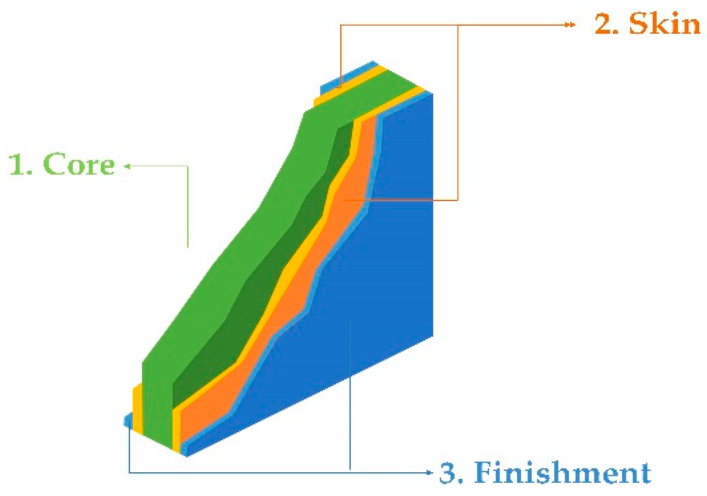
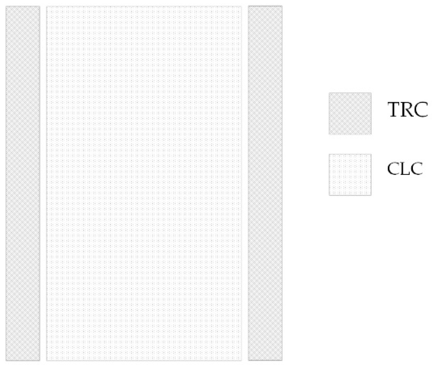
In this context, the present study performs preliminary LCA concerning the product stage of two new advanced building components, to quantify and evaluate the respective environmental impacts, with the intention of producing NZEBs with reduced embodied carbon. These two new components are: the multifunctional composite sandwich (MCS) and the composite panel made of textile reinforced concrete layers and cellular lightweight concrete cores (TRC/CLC), purposed for façade elements, and providing improved thermal insulation. This study aims to environmentally assess the building components as a whole assembly and provides detailed LCI data for the product stage of innovative materials, as well as methodology transparency, to facilitate follow-up research on the field.
For both demos, the design and the materials used are based on the circular economy perspective considering environmental, economic, and social effects along their value chain. Thus, it is expected to present improved CO2 emissions and lower cost in comparison with the respective conventional alternatives. However, in this study such a comparison is not presented, since the two demos that are examined do not reach yet the appropriate Technological Readiness Level (TRL) in order to be considered commercial and be able to compare with the benchmarking. This study provides a preassessment concerning the advanced building components focused on their production phase, including their innovative materials and processes. This assessment could support the decision-making during the production phase, as well as the respective mitigation actions, reducing the CO2 emissions and the environmental impact in a component level. In addition, it is crucial to be mentioned that the produced data (presented below) are currently missing both from the literature and the commercial data bases (e.g., Ecoinvent) and would be a valuable reference/inventory for following studies in the field, since the availability of life-cycle data (especially in the initial stages of materials’ production/manufacturing) provides the opportunity to perform relevant changes in order to reduce the total environmental impact of a final product or system.

2. Advanced Building Components

2.1. Multifunctional Composite Sandwiches (MCS)

The new multifunctional composite sandwiches (MCS) are structural lightweight modular panels with enhanced thermal efficiency performance for building envelopes, that can provide multiple desired functions, such as energy harvesting capability [31,32], improved flame retardancy [33], and self-cleaning performance [34]. They use materials with a low carbon footprint, such as recycled or natural fibers, in combination with thermoplastic resins, to produce the MCS, so that the panels are aligned with the “nearly zero-energy, zero emission” approach [3]. Moreover, the MCS concept allows the combination of several innovative raw materials (i.e., aerogels, recycled materials such as waste polymers, PCMs) [35], developing new hybrid polymer composite sandwiches, polymer matrixes, laminates, and cores, with enhanced functionalities for different applications in other industrial sectors, such as automotive and aerospace transport [31,32,33,34,35].
In this study, the standard MCS panel manufactured in Portugal is assessed (Figure 1), in terms of product stage embodied emissions. Its core is an extruded polystyrene (XPS) board, with interior and exterior skin of fiber-reinforced polymer (FRP), covered both internally and externally by a finishing of mortar. The MCS dimensions considered are 180 × 80 × 13 cm, due to current limitations of the manufacturing pilot line, although it is possible to join produced panels with structural glues and then homogenize the surface with appropriate finishing. The MCS structure and material widths considered, are shown in Table 1.
Three winter climate zones (I1, I2, and I3) are used to describe the Portuguese climate zoning (Table 2). The number of heating degree-days (HDD) at a reference temperature of 18 °C, which corresponds to the heating season, is used to establish winter climate zones [36]. The total mass of the standard panel is equal to 96.22 kg and the targeted U value is 0.35 W/(m2K), in line with the requirements for Portuguese Zone I (external walls envelope range of U values 0.24–0.5 W/(m2K)) [36,37].
However, as the thickness of the XPS is related to the U value of the MCS panel, it is possible to achieve lower U values, in agreement with the NZEB requirements, by increasing the core thickness up to 20 cm.

2.2. TRC/CLC Composite Panels

The cement-based composite, known as textile reinforced concrete (TRC), is a relatively new and promising composite. It is a high-performance composite, providing high tensile strengths and high durability, constructed by combining corrosion-resistant carbon fiber (CF) reinforcement structures in the form of mats or rods with environmentally friendly concrete structures [38,39]. Due to the strong mechanical performance and durability of the TRC material, it is possible to significantly reduce the thickness of the inner and the outer layer of the sandwich parts [39,40,41]. Huge concrete savings can be achieved by lowering the concrete cover (up to 65% cement consumption and 77% sand consumption) and the associated savings in resources and emissions can be reached [40,42], indicating the TRC as an excellent alternative material for concrete-based facades. As CFs show great exploitation potential with regard to thermomechanical properties, and are especially important as reinforcement structures for carbon concrete, scientific interest is focused on the further evolution of CF. Considering the reduction of GHG emissions and production costs, the research community is investigating sustainable alternative CF precursors from lignin, under the framework of several EU projects. Still, a lot of effort should be put at this direction, in order to fully understand the mechanisms of structure formation, and to achieve reproducible material quality [43]. At the same time, Cellular Lightweight Concrete (CLC) insulation is a special foam concrete, having similar thermal conductivity and cost to commercial Expanded Polystyrene (EPS). With the addition of silica aerogel, its thermal conductivity can even exceed 0.03 W/(mK). The heating of CLC does not cause any harmful gas emissions, or make it combustible. It offers a structurally sound and environmentally friendly alternative with insulating capabilities. It can be easily exploited as a secondary resource because it is made up 99% of minerals, such as feedstock for making cement or filler for making concrete [44].
In this study, the standard TRC/CLC panel is assessed (Figure 2) in terms of product stage embodied emissions, manufactured at HTWK Leipzig, Germany. Its core is the CLC insulation layer, covered by a front and a back layer of TRC. The TRC/CLC dimensions considered are 300 cm × 200 cm × 25 cm, with a total mass of 985.56 kg. The CLC insulation width is considered 19 cm, to reach the full sandwich panel targeted U value, equal to 0.20 W/(m2K), as provided for NZEBs in Germany, depending also on other factors, such as energy harvesting of the building. The TRC/CLC panel structure and material widths considered are shown in Table 3.

3. LCA Methodology

In the present study, the LCA methodology has been applied in accordance with the international standards of ISO 14040:2006 [16] and ISO 14044:2006 [17], and the European standards EN 15804:2012+A1:2013 [45] and EN 15978:2011 [46] for the Sustainability of Construction Works.

3.1. Goal and Scope

The aim of the current research work is to conduct an initial Life Cycle Assessment (LCA) of any potential environmental impacts of new, innovative building components, with the ultimate goal of achieving lower embodied carbon in NZEBs. The study employs Life Cycle Assessment (LCA) at the product stage (A1–A3) of building components using a “cradle-to-gate” methodology. The classification of the life cycle stages of building materials has been performed based on European standards [45,46]. Therefore, the system boundaries include A1: raw material extraction and processing, the processing of secondary material input, A2: transport to the manufacturer; and A3: manufacturing.
To determine the Functional Unit (FU) of the examined panels, a variety of functions can be considered, i.e., separating exterior from interior, self-supporting, protecting against weather; however, this study is focuses on the thermal efficiency to be provided by building components. The FU is described as “Thermal insulation of X m2 of a building element, with an insulation thickness that gives a thermal transmittance U of the element as defined in the vertical rules, with a design life span of 50 years”, with the value of X defined in the vertical rules, using the Product Environmental Footprint Category Rules (PEFCRs) for thermal insulation [47] as a basis. The declared unit for thermal insulation goods is similarly described as “thermal insulation of 1 m2 of a building element, with an insulation thickness that gives a thermal transmittance U of the element as stated in the vertical standards, with a design life duration of 50 years”.
Respectively, in the current research work, concerning the function of thermal insulation of the MCS panel, the declared unit is: “Thermal insulation for a 1 m2 wall with a thermal transmittance of 0.35 W/(m2K), or an insulation layer thickness of about 8 cm, and a design life of 50 years”; while for the function of thermal insulation of the TRC/CLC panel, the declared unit is: “A 50-year design life for thermal insulation of a 1 m2 wall with an insulation thickness that provides thermal transmittance of 0.20 W/(m2K), or around 19 cm of insulation layer”.

3.2. LCI Data Collection

Primary data collection has been performed using a tailor-made Life Cycle Inventory (LCI) questionnaire, addressed to the respective manufacturers. Background LCI data were obtained from the commercial database Ecoinvent v.3.7.1, taking into account the regional conditions for water inputs and the European conditions for electricity inputs (grid). When necessary, proxy values and data from peer-reviewed literature were also incorporated. The LCIs of the MCS panel and the TRC/CLC panel are presented in the following sections. Absolute values of the results as the primary data are not provided due to confidentiality issues; all the results are presented normalized.

3.2.1. LCI of the MCS Panel

The LCI of the MCS panel refers to the standard MCS panel (Figure 1), with a wall area of 1.44 m2 and targeted U value of 0.35 W/(m2K), presented in Table 4. The manufacturing process includes the preparation of a resin mixture, the hand layups for the application of the resin on Glass Fibre (GF) laminates and for the placement of the core, then vacuum assisted hand lamination and finally application of the finishing on both sides of the panel. However, as the manufacturing process is upgraded and the final composition of the panel is validated, it is expected that the mass values and energy demand for the manufacturing of the final product will be updated.
The LCA modelling of the MCS is performed using the following assumptions and proxies:
  • All raw materials are produced in Europe and are purchased by Portugal; transport to the manufacturer is considered negligible.
  • The XPS is approximated by the expanded polystyrene (EPS).
  • Manufacturing waste is estimated to be about 4.29 kg, going to landfill.

3.2.2. LCI of the TRC/CLC Panel

The LCI of the TRC/CLC panel refers to the standard panel (Figure 2) with a wall area of 1 m2 and targeted U value of 0.20 W/(m2K), presented in Table 5. The TRC/CLC panel consists of three main materials: the concrete of the TRC, the Carbon Fibre (CF) mat for the concrete reinforcement, and the CLC insulation. To calculate the mass of the materials for the composition of 1 m2 panel, their densities and widths were considered. For the panel manufacturing, a formwork is used. A CF mat is placed in the formwork and then a layer of concrete for TRC follows for casting and hardening. A thick layer of CLC is placed for hardening, then a layer of TRC. In total, the TRC/CLC panel is cured under atmospheric conditions until sufficient strength is gained to lift it up and to take off the mold. However, as the manufacturing process is upgraded and the final composition of the panel is validated, it is expected that the mass values and energy demand for the manufacturing of the final product will be updated.
The LCA modelling of the TRC/CLC panel is performed using the following assumptions:
  • All raw materials are produced in Europe and are purchased by Germany (taking the average EU grid); transport to the manufacturer is considered negligible.
  • The layers of the carbon fiber mat are assumed to be four in total, two at each side of the panel.
  • No energy demands occur for the panel manufacturing, due to manual applications.
  • The formwork for casting and the lift aids for demolding are reused several times before substitution, thus the material and energy requirements for their manufacturing are considered negligible.
  • Any connectors installed are not considered, due to probably low mass compared to this of the whole panel.
  • Generated waste is considered negligible.
Following, the LCIs for the materials of the panel, concrete for the TRC, CLC and CF mat are presented.

LCI of the Concrete for the TRC

The LCI of the concrete for the TRC refers to the manufacturing of 0.9 m3 concrete (Table 6). The materials used are described in general (i.e., sands), without providing specific material details, due to the principle of confidentiality. The main process of the concrete for the TRC production is the mixing of ingredients in a concrete mixer. It is assumed that the concrete mixer has 10% of loss. In particular, the water input includes the water demands for the concrete manufacturing and for cleaning the equipment. Regarding the wastes generated from manufacturing, they are divided in processing waste (solid losses in mixer) at 40%, and in cement sludge at 60%, while a sedimentation chamber is on site for the cement sludge, leading to a sediment of 10%. The processing waste and the sediment are disposed in containers and are collected by a recycling company. To assess the fraction recycled, upstream allocation is followed, thus no End of Life (EoL) treatment nor any credit of avoiding virgin material production are considered. The cement sludge remaining, along with the water for cleaning the equipment, are approximated as wastewater from concrete production.

LCI of the CLC

The LCI of the CLC refers to the manufacturing of 1 m3 concrete (Table 7). The materials used are described in general (i.e., cement), without providing specific material details, due to the principle of confidentiality. The main process of the CLC production is preparing the foam at a foam generator and then mixing constituents in the concrete mixer. The energy demands of the foaming generator are considered negligible if compared to these of the concrete mixer. There are no foam losses between the foaming generator and the concrete mixer. It is assumed that the concrete mixer has 10.4% of loss. In particular, the water input includes the water demands for the foam production, for the concrete manufacturing and for cleaning the equipment. Regarding the waste generated from manufacturing, they are divided into processing waste (losses in mixer, broken foam) at 40% and in cement sludge at 60%, while a sedimentation chamber is on site for the cement sludge, leading to a sediment of 10%. The processing waste and the sediment are disposed in containers and are collected by a recycling company. To assess the fraction recycled, the approximation followed is the same as this of the TRC. Upstream allocation is followed, thus no EoL treatment nor any credit for avoiding virgin material production are considered. The cement sludge remaining, along with the water for cleaning the equipment, are approximated as wastewater from concrete production. However, when CLC is produced at the building construction site, generated wastes are reduced while the cement sludge can be used in ground stabilization locally.

LCI of the CF Mat

For the manufacturing of the carbon fiber (CF) mat, commercial polyacrylonitrile (PAN) fibers are considered in this study as precursors. To model the production of the PAN fibers, the ELCD data created by PE International for JRC-IES, Italy, was used. However, as the CF manufacturing from this type of fiber is not available in the background databases, in terms of sub-processes, material, and energy inputs and outputs, it is approximated by respective data from literature [48], along with necessary assumptions in case of any data gaps. According to literature [48], almost double the amount of precursor is required to produce one unit of CF. The main sub-processes considered are shown in the LCI developed for 1 kg of CF (Table 8). An obstacle to the LCA of this type of CF is that the energy intensities of the manufacturing processes recorded in literature range wide, due to different scales, system boundaries and manufacturing parameters. Table 8 was based on the energy intensity deriving from literature [48] taking into account, apart from the manufacturing equipment demands, all peripherical energy demands, such as lighting, exhaust, and fresh air fans. It is assumed that any other auxiliary materials used for the manufacturing, i.e., gases, compressed air, solutions, are negligible to the assessment, due to recycling loops or reuse several times before substitution. High temperatures cause the majority of the precursor fiber’s non-carbon components to volatilize into diverse gases such methane, hydrogen, and ammonia, leaving only 50–55 percent of the initial precursor wt. However, no data is available for the moment regarding generated waste, in terms of waste heat and air emissions.
For the development of 1 m2 of CF mat, an LCI was developed through lab-scale manufacturing data (Table 9). The manufacturing process includes the placement of fixpoints on a frame, winding the carbon roving around the fixpoint frame, coating the fiber with resin, and drying the resin via oven. After drying, the CF mat is removed from the fixpoint frame and is placed in the formwork. As the fixpoint frame can be reused several times for CF mat manufacturing, it is not considered as a material and energy input. The produced CF mat weights 0.21515 kg/m2. The generated waste consists of 1.2 g of CF and 0.15 g of epoxy resin, which are collected by a recycling company and are approached by upstream allocation. It is expected that more specific manufacturing data for the CF and the CF mat will become available soon, so the LCI will be updated accordingly.

3.3. LCIA

The Life Cycle Impact Assessment (LCIA) was implemented by the SimaPro software v9.1.1.7 using the ILCD 2011 Midpoint method, including 16 midpoint impact categories, as presented in Table 10, with their abbreviations and units. The European Commission published the ILCD 2011 Midpoint approach in 2012. According to the ILCD guidance document “Recommendations for Life Cycle Impact Assessment in the European context-based on existing environmental effect assessment models and factors (EC-JRC, 2011)”, it promotes the proper application of the characterization elements for impact assessment [49]. This study focuses on the impact category of Climate change: Global Warming Potential (GWP), determining the greenhouse effect over a 100-year time horizon.
In Appendix A the 16 midpoint categories are presented together with the raw LCA results for both the MCS panel and the TRC-CLC-TRC panel. Appendix A presents the 16-midpoint impact categories considered in this study, along with the LCA raw results for the TRC/CLC panel and the MCS panel. Raw results for both panels refer to a wall area of 1 m2. It is highlighted though, that the two panels examined are not compared to one another in terms of environmental impacts, since they have different thickness and targeted U value. The TRC/CLC panel has a thickness of 0.25 m with targeted U value equal to 0.2 W/m2K, while the MCS panel has a thickness of 0.13 m with targeted U value equal to 0.35 W/m2K.

4. Results

4.1. General Introduction

The LCIA results for the building components under investigation are shown in the following figures as staked 100% graphs for all the impact categories covered. For reasons of confidentiality, results are presented in a normalized form in advance. The material and energy inputs and outputs for each component under consideration are shown in the legends.

4.2. Results for MCS

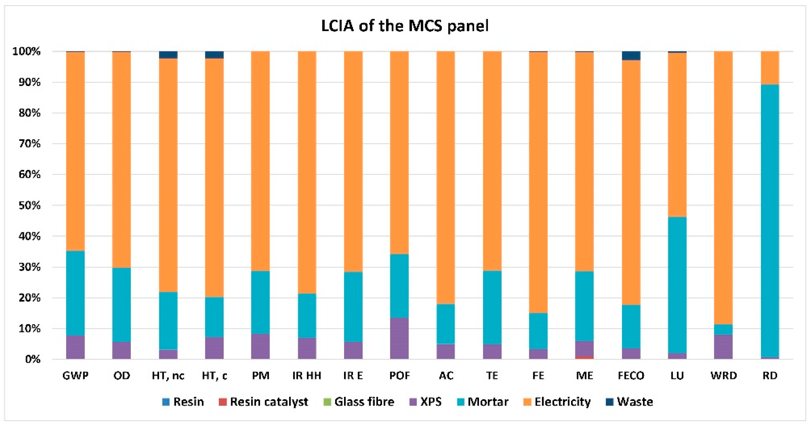
Figure 3 presents the LCIA results for the standard MCS panel. The GWP of the product stage of the MCS panel is 169 kg CO2 eq per m2. According to the environmental hotspot analysis, the electricity required for the MCS manufacturing represents the largest share for most of the impact categories addressed, contributing to climate change by 64%. As shown at the LCI of the MCS (Table 4) concerning the energy inputs required for manufacturing, it is noticed that the preparation of the resin does not present high energy demands; in contradiction to the general exhaust, operating during the rest of the manufacturing process, which is time-consuming, including hand layup applications as well as vacuum assisted lamination lasting for over 12 h. However, the MCS manufacturing is planned to be upscaled, moving from time-consuming hand laminations to fast automated ones, therefore crucially reducing the operation time of the mechanical ventilation.
The other climate change contributors are the mortar with 27.5% and the XPS with 7.7%. The resin, the resin catalyst, and the glass fiber do not show significant contribution to any of the impact categories assessed, as their amount is very small in the total MCS panel mass. In addition, the generated waste does not significantly affect the impact categories assessed. It is also noticed that the mortar plays a crucial role in mineral, fossil, and renewable resource depletion, with a contribution of 88%. In particular, the mortar examined is lime mortar, mainly containing limestone, the most widely used crushed rock, the mining of which directly leads to the scarcity of mineral resources.
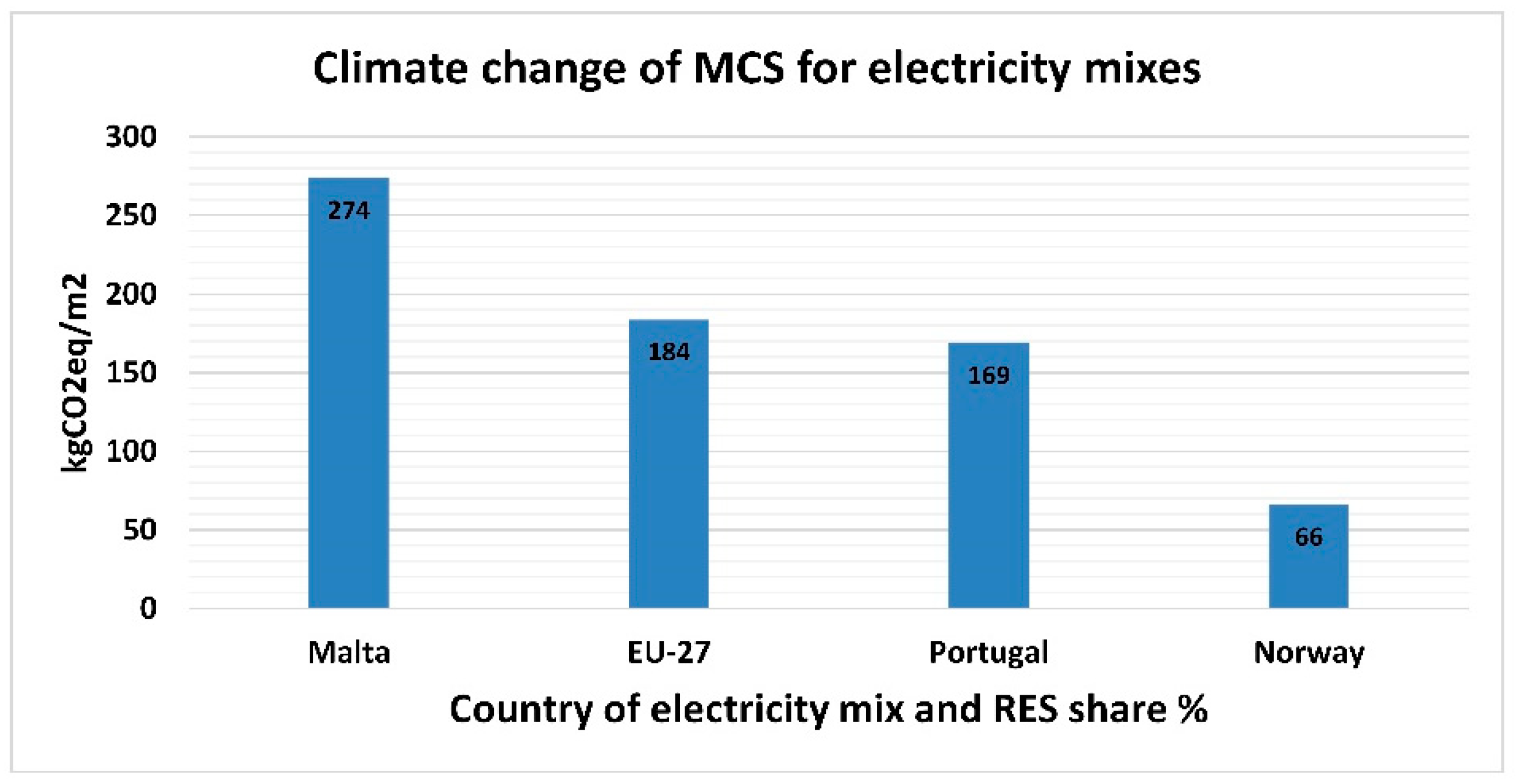
As electricity is the main contributor to most of the environmental impact categories assessed, including climate change, which is the basic focus of this study in terms of embodied emissions, a sensitivity analysis was performed considering different electricity grids of Europe to examine the influence of different electricity mixes in the climate change impact of the MCS. Apart from the Portugal grid that was already considered, the electricity mix of Norway was examined as highly decarbonized, that of Malta as slightly decarbonized and the European as an average, using the Renewable Energy Sources (RES) share for year 2019 [50].
The datasets used from Ecoinvent reflect the share of electricity technologies valid for the year 2016, and have been extrapolated from 2017 to 2019 with the uncertainty adjusted accordingly. The sensitivity analysis, presented in Figure 4, illustrates that the decarbonization level of the electricity grid considered plays a significant role in the environmental impact of climate change. If the Norway grid is selected, with a Renewable Energy Sources (RES) share of 74.41% of gross final energy consumption, the climate change of the MCS goes from 169 kg CO2 eq/m2 to 66 kg CO2 eq/m2, leading to a reduction in the climate change impact of 60%. On the other hand, when the Malta grid is selected, having a RES share of 8.23%, the climate change of the MCS goes to 274 kg CO2 eq/m2, leading to an increased impact by 62%. Thus, climate change is very sensitive to the RES share of the electricity grid considered and the respective impact decreases as the decarbonization levels of the electricity mixes increase. This analysis implies that when performing a LCIA it is important to consider the local electricity manufacturing conditions, rather than use European or other averages, for increased accuracy in the results. In addition, decarbonization paths of electricity grids are expected to be intensified during the next years, which will contribute to the mitigation of climate change.

4.3. Results for TRC-CLC-TRC

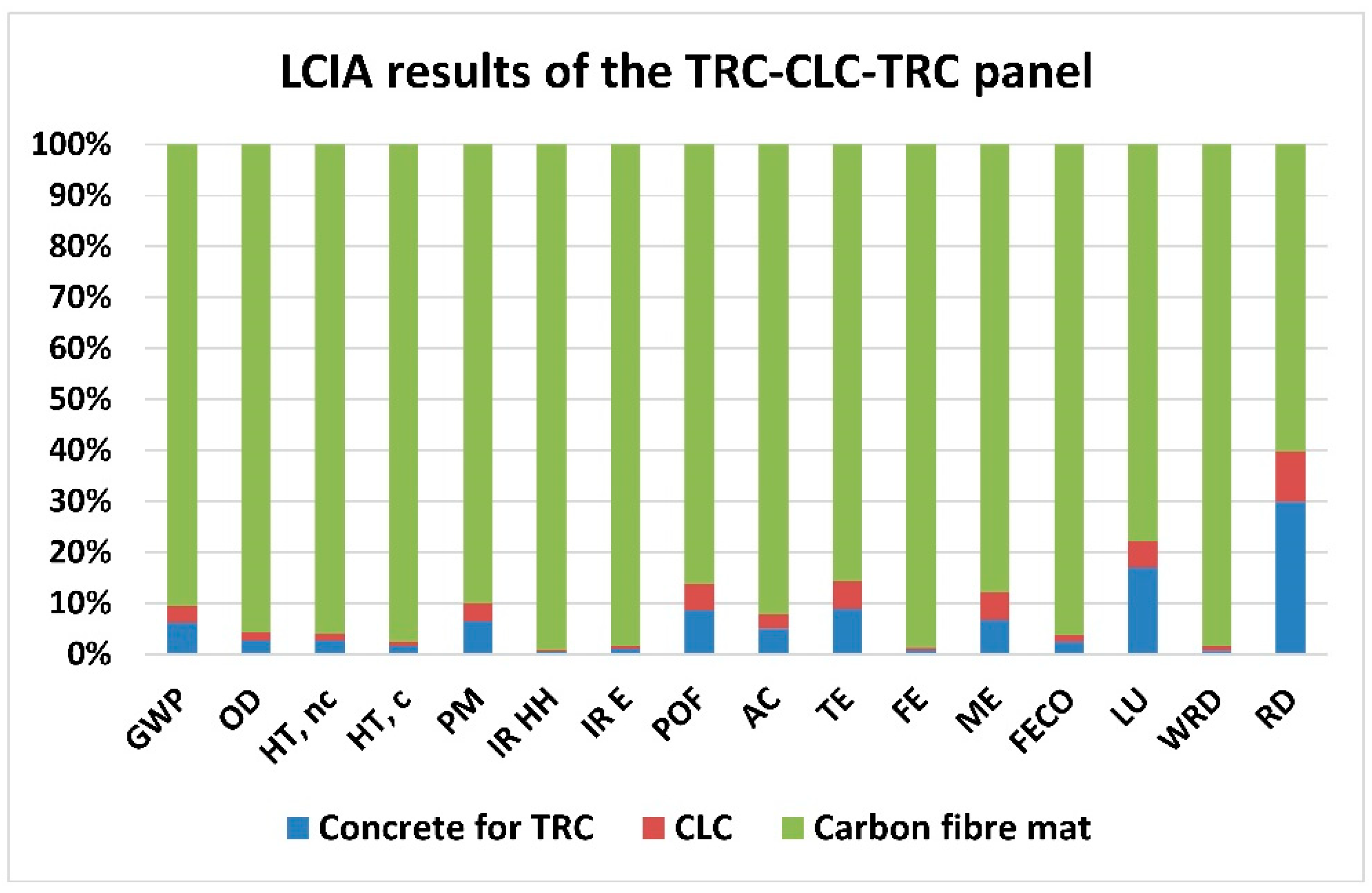
Figure 5 presents the LCIA results for the standard TRC-CLC-TRC panel. The GWP of the product stage of the panel is 313 kg CO2 eq per m2. According to the environmental hotspot analysis, the CF mat represents the largest share for all the impact categories addressed, contributing to climate change by 90.6%, followed by the concrete for TRC with 6.1% and the CLC with 3.3%.
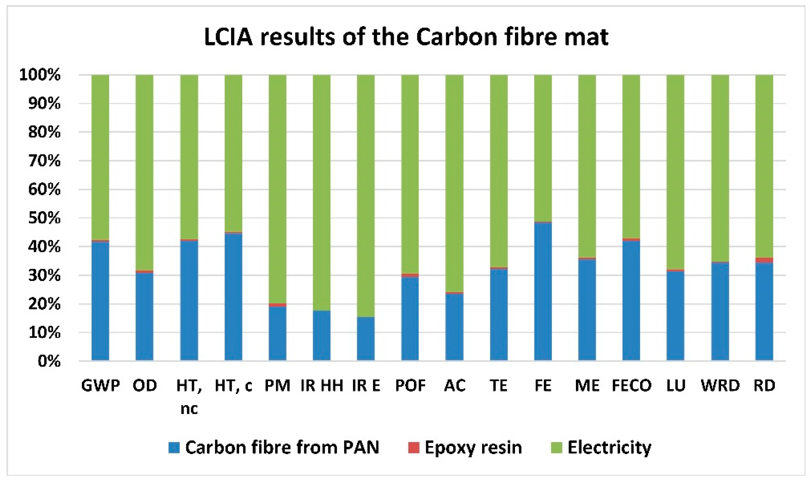
When investigating closer the CF mat, it is noticed that the electricity required is the main environmental contributor to all impact categories assessed, followed by the CF, while the epoxy resin burden is considered negligible (
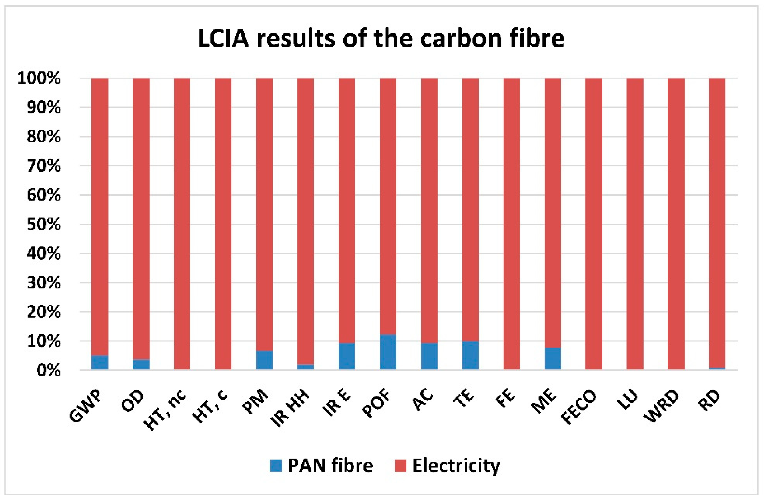
Figure 6). Particularly for climate change, electricity has a share of 58% and CF a share of 41%. Finally, a closer look at the manufacturing of the CF, reveals again that the electricity required is the main environmental contributor to all impact categories assessed, (Figure 7), with a share of 95% to climate change.

4.4. Comparison of Materials

The comparison of the two panels examined with respective conventional alternatives in terms of environmental impacts, would be of high interest and added value in this research; however, this is not included in the present study, since the two panels are still under development and do not yet reach the appropriate Technological Readiness Level (TRL), so as to enable comparisons with commercial products. Furthermore, the two panels examined are not compared to one another, since they present different thickness and targeted U value, as well as they are planned to provide different functionalities.
Nevertheless, comparisons concerning the materials of the panels are also of high importance, since they can reveal any alignments or diversions compared to similar material alternatives. In this context, the CLC of the TRC-CLC-TRC panel is selected to be presented for an indicative comparison with other insulation foam concretes from literature, in terms of climate change potential, considering the importance of this material operating as a thermal insulator. Table 11 illustrates the Global Warming Potential (GWP) of the CLC and other foam concretes in literature, considering the product stage (A1–A3) [51], showing that the CLC examined in comparison to other foam concretes is aligned in terms of climate change potential.
Considering the aforementioned indicative comparison regarding the CLC thermal insulation material, its production stage does not present any climate change draw back, concerning other similar foam concretes from literature. However, when the whole TRC-CLC-TRC panel is considered, the increased energy demands for the manufacturing of the carbon fibers must be tackled, in order to minimize the respective embodied emissions. Thus, future work includes the equipment upgrade of the manufacturing pilot line, as well as the use of lignin fibers instead of carbon fibers, to balance energy-material emissions. Moreover, the project research is focused on the integration of silica or/and cellulose aerogels into the CLC, to further improve thermal conductivity. As for the MCS panel, its manufacturing process is planned to be upgraded in the near future, while different material compositions are examined by the manufacturing partner; so, the mass values and energy demands of the final composition validated will be updated accordingly. It is also worth mentioning that not all the life cycle stages of the panels have been assessed in this study. Since the burden of embodied emissions lies at the product stage (A1–A3) already examined, it is expected that a full life cycle analysis of the products, including end of life scenarios with credits of reusability and recyclability, will balance the total embodied emissions of the panels across their value chains, if compared to conventional similar building alternatives.

5. Discussion

Building systems, materials, components, and product availability, have all significantly expanded in recent years. The innovative design and construction techniques that make buildings stronger, safer, longer-lasting, environmentally friendly, and more effective have been made possible by these technological improvements. Thus, building owners and decision-makers have a variety of options to choose what better fits their needs when looking into new technologies and components that can enhance and improve their facilities. However, opportunities to improve building performance and gradually decrease both operating costs and environmental footprint are often missed because innovative, less-known technologies do not receive significant attention. Building owners, operators, and design experts, can compare multiple innovative technologies and choose the best suitable to accomplish a certain goal by using research studies produced by EC-funded projects, particularly the Research Innovation Actions (RIA).
Materials for thermal insulation are crucial for decreasing buildings’ energy costs and consumption, making them a key-player towards climate change mitigation and green energy transition. Energy and CO2 balance, environmental compatibility, and the likelihood of material recycling or disposal, each contribute significantly to the environmental evaluation. LCA offers structural engineers the opportunity to incorporate environmental factors in the decision-making of buildings, promoting a more efficient use of resources throughout the whole life cycle of a building, and minimizing the environmental impacts of construction activities. However, it is difficult to decide whether a technology or a material/component is environmentally friendly. This is feasible upon the availability of a wholistic and careful analysis that takes into account all the respective parameters. Thus, established research findings of LCA on novel components and/or materials can assist in the protection of the environment through the development of new building structural components, products, and manufacturing techniques.
This paper focused on the preliminary Life Cycle Assessment (LCA) of two advanced multifunctional building components aiming to achieve lower embodied emissions in NZEBs. For the two panels examined, results indicated electricity demands in manufacturing as the main contributor at the product stage to all the environmental impact categories for the TRC-CLC-TRC panel, and to all the environmental impact categories, apart from mineral, fossil, and renewable resource depletion, for the MCS panel. This impact category is highly affected by the mortar integrated in the MCS panel, as this is lime mortar, the mining of which directly leads to the scarcity of mineral resources. Since the GHG emissions highly depend on the electricity grid source, energy efficiency measures and cleaner electricity grid mixes can have a significant influence on the environmental performance. Despite that, comparisons between the two panels or with conventional sandwich panel alternatives cannot be performed, as explained above. An indicative comparison of the CLC as insulation material, integrated into the TRC-CLC-TRC panel, with other foam concretes from literature was presented, indicating that its climate change potential does not diverse from other insulator alternatives. Thus, CLC can consist of a promising candidate for further thermal insulation building assemblies.
The main challenge identified during this research work was the lack of easily accessible Life Cycle Inventory (LCI) data that can be used in decision-making by practitioners, end users, and researchers. However, the above limitation, even considered as crucial for the research accomplishment, was tackled through the development of real-data detailed LCIs, achieved by intensive iterative communication with the respective manufacturing partners. When it comes to comparisons of building materials and components, it is important to mention that special attention should be paid to the consistency between LCA methodologies, system boundaries, and functional units. In addition, properties and functionalities should also be considered for high-quality comparison results. To this direction, a detailed description of the manufacturing processes included in the system boundaries, detailed LCIs along with proxies and assumptions, as well as material/component properties like U values, should be mentioned in literature and databases.

6. Conclusions

This study’s purpose was to minimize embodied carbon by performing a preliminary Life Cycle Assessment (LCA) of innovative building components that are now under development, and will be scaled up in the coming months. For the thermal insulation components examined, results indicated that the electricity required for manufacturing presents a significant contribution to climate change, and to other environmental impact categories assessed, especially when it comes to the manufacturing of carbon fibers. At the same time, less environmental impact is caused by the raw materials used. This outcome implies that special effort should be put on the optimization of manufacturing in terms of energy demands. The sensitivity analysis performed for the MCS showed the important influence of the electricity mix to the climate change impact, according to the decarbonization level of the electricity grids at a national level. Thus, when performing LCA it is important to consider the local electricity conditions, rather the European or other averages, for increased accuracy in the final results. As the manufacturing lines addressed are planned to be upscaled, reducing electricity requirements, and as the electricity grids are gradually decarbonized, the mitigation of climate change impact is expected in the near future. The comparison in terms of climate change impact performed between the CLC and similar foam concretes shown that the innovative materials of the two panels examined are aligned with the alternatives in literature. This study also reveals and tackles a general necessity to enrich and update the LCI databases for advanced building materials and components, as there is a significant lack of data regarding their environmental impacts in current literature. Finally, the detailed LCIs developed for the two building panels will be utilized as a benchmark for future LCA, when the panels are going to finalized in terms of design and composition, as well as validated for their properties and functionalities.

Author Contributions

Conceptualization, D.A. and E.P.K.; methodology, F.P. and A.G.; investigation, R.B., A.K. and J.S.; resources, A.A., S.S., D.A. and E.P.K.; writing—original draft preparation, F.P., A.G., P.V., R.B., D.A., A.K. and S.S.; writing—review and editing, E.P.K. and S.S.; visualization, J.S., A.A., S.S., A.K. and F.P.; supervision, D.A., A.G., P.V., E.P.K. and F.P.; funding acquisition, E.P.K. All authors have read and agreed to the published version of the manuscript.

Funding

The activities presented in this paper were carried out as part of the H2020 project “iclimabuilt-Functional and advanced insulating and energy harvesting/storage materials across climate adaptive building envelopes” 560 (Grant Agreement no. 952886).

Institutional Review Board Statement

Not applicable.

Informed Consent Statement

Not applicable.

Data Availability Statement

Not applicable.

Acknowledgments

This research has received funding from the European Union’s Horizon 2020 research and innovation programme iclimabuilt, under Grant Agreement No. 952886.

Conflicts of Interest

The authors declare no conflict of interest.

Abbreviations

ACAcidification
CFCarbon Fiber
CLCCellular Lightweight Concrete
ECEuropean Commission
ELCDEuropean reference Life Cycle Database
EoLEnd of Life
EPBDEnergy Performance of Buildings Directive
EPSExpanded polystyrene
FEFreshwater eutrophication
FECOFreshwater ecotoxicity
FRPFiber-reinforced polymer
GFGlass Fiber
GHGGreenhouse Gas emissions
GWPClimate change
HT, cHuman toxicity, cancer effects
HT, ncHuman toxicity, non-cancer effects
IR EIonizing radiation E (interim)
IR HHIonizing radiation HH
LCALife Cycle Assessment
LCILife Cycle Inventory
LCIALife Cycle Impact Assessment
LULand use
MEMarine eutrophication
MCSMultifunctional Composite Sandwich
NZEBsNearly Zero Energy Buildings
ODOzone depletion
PANPolyacrylonitrile
PCMPhase Change Materials
PEFCRsProduct Environmental Footprint Category Rules
PMParticulate matter
POFPhotochemical ozone formation
RDMineral, fossil & ren resource depletion
RESRenewable Energy Sources
TETerrestrial eutrophication
TRCTextile Reinforced Concrete
WRDWater resource depletion
XPSExtruded polystyrene

Appendix A

Impact CategoryAbbreviationUnitsTRC/CLC PanelMCS Panel
Climate changeGWPkg CO2 eq312.564633168.750416
Ozone depletionODkg CFC-11 eq0.0000310.000008
Human toxicity, non-cancer effectsHT, ncCTUh0.0000990.000032
Human toxicity, cancer effectsHT, cCTUh0.0000260.000007
Particulate matterPMkg PM2.5 eq0.0914070.067384
Ionizing radiation HHIR HHkBq U235 eq109.3673069.336156
Ionizing radiation E (interim)IR ECTUe0.0002780.000031
Photochemical ozone formationPOFkg NMVOC eq0.6085870.558255
AcidificationACmolc H+ eq1.2739771.114554
Terrestrial eutrophicationTEmolc N eq2.3995701.911969
Freshwater eutrophicationFEkg P eq0.3173410.050763
Marine eutrophicationMEkg N eq0.2781910.180876
Freshwater ecotoxicityFECOCTUe4010.1949501453.282357
Land useLUkg C deficit237.017820161.846745
Water resource depletionWRDm3 water eq2.5357470.631790
Mineral, fossil and ren resource depletionRDkg Sb eq0.0035030.004468

References

  1. European Commision. The European Green Deal, COM(2019) 640 Final; European Commision: Brussels, Belgium, 2019. [Google Scholar]
  2. European Commission—Department: Energy. Focus: Energy Efficiency in Buildings. 2020. Available online: https://ec.europa.eu/info/news/focus-energy-efficiency-buildings-2020-lut-17_en (accessed on 30 August 2022).
  3. European Commision. Directive 2010/31/EU of the European Parliament and of the Council of 19 May 2010 on the Energy Performance of Buildings (Recast) [2010] OJ L 153/13; European Commision: Brussels, Belgium, 2010. [Google Scholar]
  4. European Commission. Energy Performance of Buildings Directive. Available online: https://energy.ec.europa.eu/topics/energy-efficiency/energy-efficient-buildings/energy-performance-buildings-directive_en (accessed on 30 August 2022).
  5. European Commision. Directive (EU) 2018/844 of the European Parliament and of the Council of 30 May 2018 Amending Directive 2010/31/EU on the Energy Performance of Buildings and Directive 2012/27/EU on Energy Efficiency [2018] OJ L 156/75; European Commision: Brussels, Belgium, 2018. [Google Scholar]
  6. European Commission. A Renovation Wave for Europe—Greening Our Buildings, Creating Jobs, Improving Lives SWD(2020) 550 Final COM(2020) 662 Final; European Commission: Brussels, Belgium, 2020. [Google Scholar]
  7. European Commission. Proposal for a Directive of the European Parliament and of the Council on the Energy Performance of Buildings (Recast) [2021] COM/2021/802 Final; European Commission: Brussels, Belgium, 2021. [Google Scholar]
  8. Affordable Zero Energy Buildings (AZEB). nZEB Demo Buildings Environmental Impact through LCA. Available online: https://azeb.eu/report-nzeb-demo-buildings-environmental-impact-through-lca/ (accessed on 30 August 2022).
  9. Erhorn-Kluttig, H.; Erhorn, H. National applications of the NZEB definition—The complete overview. In Fraunhofer Institute for Building Physics, Concerted Action EPBD, Horizon 2020 Project, GA 692447; Fraunhofer Institute: Munich, Germany, 2018. [Google Scholar]
  10. D’Agostino, D.; Zangheri, P.; Cuniberti, B.; Paci, D.; Bertoldi, P. Synthesis Report on the National Plans for NZEBs; Publications Office of the European Union: Luxembourg, 2016. [Google Scholar] [CrossRef]
  11. BPIE (Buildings Performance Institute Europe). Nearly Zero: A review of EU Member State Implementation of New Build Requirements; BPIE: Brussels, Belgium, 2021. [Google Scholar]
  12. Chastas, A.; Theodosiou, Τ.; Bikasa, D.; Kontoleon, A. Embodied Energy and Nearly Zero Energy Buildings: A Review in Residential Buildings. Procedia Environ. Sci. 2017, 38, 554–561. [Google Scholar] [CrossRef]
  13. London Energy Transformation Initiative (LETI). LETI Climate Emergency Design Guide; LETI: London, UK, 2020. [Google Scholar]
  14. World Green Building Council. Bringing Embodied Carbon Upfront; World Green Building Council: London, UK, 2019. [Google Scholar]
  15. Yan, H.; Shen, Q.; Fan, L.; Wang, Y.; Zhang, Y. Greenhouse gas emissions in building construction: A case study of One Peking in Hong Kong. Build. Environ. 2010, 45, 949–955. [Google Scholar] [CrossRef] [Green Version]
  16. ISO 14040:2006; Environmental Management—Life Cycle Assessment-Principles and Framework. International Organization for Standardization: Geneva, Switzerland, 2006.
  17. ISO 14044:2006; Environmental Management—Life Cycle Assessment-Requirements and Guidelines. International Organization for Standardization: Geneva, Switzerland, 2006.
  18. Institute for Environment and Sustainability—Joint Research Centre—European Commission. International Reference Life Cycle Data System (ILCD) Handbook—General guide for Life Cycle Assessment—Detailed guidance, EUR 24708, 1st ed.; European Commission: Luxembourg, 2010. [Google Scholar]
  19. Jain, M.; Rawal, R. Emissions from a net-zero building in India: Life cycle assessment. Build. Cities 2022, 3, 398–416. [Google Scholar] [CrossRef]
  20. Wang, Y.; Yang, X.; Hou, Q.; Tao, J.; Dong, J. Quantitative Study on the Life-Cycle Carbon Emissions of a Nearly Zero Energy Building in the Severe Cold Zones of China. Sustainability 2022, 14, 1448. [Google Scholar] [CrossRef]
  21. Asdrubali, F.; Grazieschi, G. Life cycle assessment of energy efficient buildings. Energy Rep. 2020, 6, 270–285. [Google Scholar] [CrossRef]
  22. Belussi, L.; Barozzi, B.; Bellazzi, A.; Danza, L.; Devitofrancesco, A.; Fanciulli, C.; Ghellere, M.; Guazzi, G.; Meroni, I.; Salamone, F.; et al. A review of performance of zero energy buildings and energy efficiency solutions. J. Build. Eng. 2019, 25, 100772. [Google Scholar] [CrossRef]
  23. Magrini, A.; Lentini, G.; Cuman, S.; Bodrato, A.; Marenco, L. From nearly zero energy buildings (NZEB) to positive energy buildings (PEB): The next challenge—The most recent European trends with some notes on the energy analysis of a forerunner PEB example. Dev. Built Environ. 2020, 3, 100019. [Google Scholar] [CrossRef]
  24. Wu, W.; Skye, H.M. Residential net-zero energy buildings: Review and perspective. Renew Sustain. Energy Rev. 2021, 142, 110859. [Google Scholar] [CrossRef]
  25. Directive (EU) of the European Parliament and of the Council. Energy Performance of Buildings (Recast); European Commision: Brussels, Belgium, 2021. [Google Scholar]
  26. Li, D.; Wu, Y.; Wang, B.; Liu, C.; Arıcı, M. Optical and thermal performance of glazing units containing PCM in buildings: A review. Construct. Build. Mater. 2020, 233, 117327. [Google Scholar] [CrossRef]
  27. Yılmaz, E.; Aykanat, B.; Çomak, B. Environmental life cycle assessment of rockwool filled aluminum sandwich fa-cade panels in Turkey. J. Build. Eng. 2022, 50, 104234. [Google Scholar] [CrossRef]
  28. Laiblová, L.; Pešta, J.; Kumar, A.; Hájek, P.; Fiala, C.; Vlach, T.; Kočí, V. Environmental Impact of Textile Reinforced Concrete Facades Compared to Conventional Solutions—LCA Case Study. Materials 2019, 12, 3194. [Google Scholar] [CrossRef] [PubMed] [Green Version]
  29. Samania, P.; Mendes, A.; Leal, V.; Guedes, J.M.; Correia, N. A sustainability assessment of advanced materials for novel housing solutions. Build. Environ. 2015, 92, 182–191. [Google Scholar] [CrossRef] [Green Version]
  30. Füchsl, S.; Rheude, F.; Röder, H. Life cycle assessment (LCA) of thermal insulation materials: A critical review. Clean. Mater. 2022, 5, 100119. [Google Scholar] [CrossRef]
  31. Fredi, G.; Dorigato, A.; Fambri, L.; Pegoretti, A. Multifunctional structural composites for thermal energy storage. Multifunct. Mater. 2020, 3, 042001. [Google Scholar] [CrossRef]
  32. Chen, B.; Jia, Y.; Narita, F.; Wang, C.; Shi, Y. Multifunctional cellular sandwich structures with optimised core topologies for improved mechanical properties and energy harvesting performance. Compos. Part B Eng. 2022, 238, 109899. [Google Scholar] [CrossRef]
  33. Javaid, A.; Hashmi, S. Development of the Fire-Retardant Truss Core Sandwich Structures Using Carbon Fiber Reinforced Epoxy Composites. Fire Technol. 2022, 58, 1493–1507. [Google Scholar] [CrossRef]
  34. Bai, Y.; Zhang, H.; Shao, Y.; Zhang, H.; Zhu, J. Recent Progresses of Superhydrophobic Coatings in Different Application Fields: An Overview. Coatings 2021, 11, 116. [Google Scholar] [CrossRef]
  35. Dębska, B.; Lichołai, L.; Szyszka, J. Innovative composite on the basis of an aerogel mat with an epoxy resin modified with PET waste and PCM, in E3S Web of Conferences 44, 00031. In Proceedings of the 10th Conference on Interdisciplinary Problems in Environmental Protection and Engineering EKO-DOK, Polanica-Zdroj, Poland, 16–18 April 2018. [Google Scholar]
  36. Resende, H.C.J. The nZEB Requirements for Residential Buildings: An Analysis of Thermal Comfort and Actual Energy Needs in Portuguese Climate. Sustainability 2021, 13, 8277. [Google Scholar] [CrossRef]
  37. Portaria n.° 379-A/2015. Ministerio Do Ambiente, Ordenamento Do Territorio Energia. Available online: https://poseur.portugal2020.pt/media/38402/port-379_a-rect-349_b.pdf (accessed on 30 August 2022).
  38. Böhm, R.; Thieme, M.; Wohlfahrt, D.; Wolz, D.S.; Richter, B. Reinforcement Systems for Carbon Concrete Composites Based on Low-Cost Carbon Fibers. Fibers 2018, 6, 56. [Google Scholar] [CrossRef]
  39. Holschemacher, K. Application of Textile Reinforced Concrete in Precast Concrete Industry. IOP Conf. Ser. Mater. Sci. Eng. 2020, 753, 042086. [Google Scholar] [CrossRef]
  40. Kraft, R.; Kahnt, A.; Grauer, O.; Thieme, M.; Wolz, D.; Schlüter, D.; Tietze, M.; Curbach, M.; Holschemacher, K.; Jäger, H. Advanced Carbon Reinforced Concrete Technologies for Façade Elements of Nearly Zero-Energy Buildings. Materials 2022, 15, 1619. [Google Scholar] [CrossRef] [PubMed]
  41. Kong, K.; Mesticou, Z.; Michel, M.; Larbi, A.; Junes, A. Comparative characterization of the durability behaviour of textile-reinforced concrete (TRC) under tension and bending. Compos. Struct. 2017, 179, 107–123. [Google Scholar] [CrossRef]
  42. Scope, C.; Guenther, E.; Schütz, J.e.a. Aiming for life cycle sustainability assessment of cement-based composites: A trend study for wall systems of carbon concrete Session 4—Circular economy for building with secondary constructionmaterials to minimise resource u, in Dresden Nexus Conference 2020—Session 4—Circular economy for building with secondary constructionmaterials to minimise resource use and land use. Civ. Eng. Des. 2020, 2, 143–158. [Google Scholar]
  43. Koumoulos, E.; Trompeta, A.-F.; Santos, R.; Martins, M.; dos Santos, C.; Iglesias, V.; Böhm, R.; Gong, G.; Chiminelli, A.; Verpoest, I.; et al. Research and Development in Carbon Fibers and Advanced High-Performance Composites Supply Chain in Europe: A Roadmap for Challenges and the Industrial Uptake. J. Compos. Sci. 2019, 3, 86. [Google Scholar] [CrossRef] [Green Version]
  44. Flansbjer, M.; Portal, N.W.; Vennetti, D.; Mueller, U. Composite Behaviour of Textile Reinforced Reactive Powder Concrete Sandwich Façade Elements. Int. J. Concr. Struct. Mater. 2018, 12, 71. [Google Scholar] [CrossRef]
  45. CEN. Sustainability of Construction Works-Environmental Product Declarations—Core Rules for the Product Category of Construction Products; 15804:2012+A1:2013; Comité Européen de Normalisation: Brussels, Belgium, 2012. [Google Scholar]
  46. CEN. Sustainability of Construction Works—Assessment of Environmental Performance of Buildings—Calculation Method; EN 15978:2011; Comité Européen de Normalisation: Brussels, Belgium, 2011. [Google Scholar]
  47. European Commision. Thermal Insulation Products in Building: PEFCR Report; European Commision: Brussels, Belgium, 2019. [Google Scholar]
  48. Antal, D.; Dilger, N.; Kaluza, A.; Creighton, C.; Kara, S.; Varley, R.; Herrmann, C.; Thiede, S. Modelling and analysis of the energy intensity in polyacrylonitrile (PAN) precursor and carbon fibre manufacturing. J. Clean. Prod. 2021, 303, 127105. [Google Scholar]
  49. European Commission, Joint Research Centre, Institute for Environment and Sustainability. Characterisation Factors of the ILCD Recommended Life Cycle Impact Assessment Methods. Database and Supporting Information, 1st ed.; European Commision: Brussels, Belgium, 2012. [Google Scholar]
  50. European Environmental Agency (EEA). Share of Energy Consumption from Renewable Sources in Europe. 2022. Available online: https://www.eea.europa.eu/ims/share-of-energy-consumption-from (accessed on 1 September 2022).
  51. Antypa, D.; Vlysidis, A.; Gkika, A.; Petrakli, F.; Kraft, R.; Böhm, R.; Eckert, K.M.; Smirnova, I.; Suchorzewski, J.; Koumoulos, E. Life cycle assessment of advanced building materials towards NZEBs. In Proceedings of the E3S Web of Conferences 349, Stuttgart, Germany, 5–8 September 2021. [Google Scholar]
  52. Zimele, Z.; Sinka, M.; Korjakins, A.; Bajare, D.; Sahmenko, G. Life Cycle Assessment of Foam Concrete, Production in Latvia. Environ. Clim. Technol. 2019, 23, 3. [Google Scholar] [CrossRef] [Green Version]
  53. Lim, S.K.; Tan, C.S.; Li, B.; Tung-Chai, L. Utilizing high volumes quarry wastes in the production of lightweight foamed concrete. Constr. Build. Mater. 2017, 151, 441–448. [Google Scholar] [CrossRef]
Figure 1. The standard MCS panel.
Sustainability 14 16218 g001
Figure 2. The standard TRC-CLC-TRC panel.
Sustainability 14 16218 g002
Figure 3. The LCIA results for the standard MCS panel.
Sustainability 14 16218 g003
Figure 4. Climate change of MCS for electricity mixes.
Sustainability 14 16218 g004
Figure 5. The LCIA results for the TRC-CLC-TRC panel.
Sustainability 14 16218 g005
Figure 6. The LCIA results for the Carbon fiber mat.
Sustainability 14 16218 g006
Figure 7. The LCIA results for the carbon fiber.
Sustainability 14 16218 g007
Table 1. MCS structure and widths *.
MaterialPositionThickness (cm)Density (kg/m3)Thermal Conductivity Lamda Value λ (W/mK)U-Value (W/m2K)
XPS1. Core8350.0280.35
FRP2. Skin Interior0.51.76--
FRP2. Skin Exterior0.51.76--
Mortar3. Finishment Interior21600--
Mortar3. Finishment Exterior21600--
* Thermal conductivity and U values are provided for the thermal insulation materials of the panel examined, which in this case is XPS.
Table 2. Criteria for defining the Portuguese climate zones.
Winter CriteriaHDD ≤ 13001300 < HDD ≤ 1800HDD > 1800
Winter Climate ZoneI1I2I3
Altitude (m)4–83247–483572–1017
Table 3. TRC/CLC panel structure and widths *.
MaterialPositionThickness (cm)Density (kg/m3)Thermal Conductivity Lamda Value λ (W/mK)U-Value (W/m2K)
TRCFront Layer32375--
CLCInsulation Layer191100.040.21
TRCBack Layer32375--
Carbon Fibre (CF) MatIncluded in TRC0.372--
* Thermal conductivity and U values are provided for the thermal insulation materials of the panel examined, which in this case is CLC.
Table 4. LCI of the MCS panel.
Material Inputs
MaterialsDensity (kg/m3)Mass (kg)
XPS354.48
Mortar160096.0
FRP consisted of:1.760.0264
Glass fibre 0.0178
Resin 0.0060
Resin catalyst 0.0026
Energy Inputs
InfrastructureProcessesElectricity (kWh) Portugal Grid
Resin MixerMechanical Stirring0.8
Fume hood15.8
Oven with vacuum systemVacuum assisted Lamination (12 h oven)28.0
Ventilation-General exhaustVacuum and Hand Layup Applications375.0
Table 5. LCI of the TRC/CLC panel.
Material Inputs
MaterialsDensity (kg/m3)Mass (kg)
Concrete for TRC2375142.50
Carbon Fibre (CF) Mat720.8606
CLC11020.90
Energy Inputs
InfrastructureProcessesElectricity (kWh) German Grid
FormworkCasting0
Curing (atmospheric conditions)
Lift aidsDemolding0
Table 6. LCI of the Concrete for TRC (unit of reference 0.9 m3).
Material Inputs
MaterialsMass (kg)
Cement426.1
Sands793
Gravel973.9
Plasticizer2.6
Water179
Water for cleaning47
Energy Inputs
InfrastructureElectricity (kWh) German Grid
Concrete Mixer3.2
Table 7. LCI of the CLC (unit of reference 1 m3).
Material Inputs
MaterialsMass (kg)
Cement70.2
Limestone17.6
Foaming agent2.0
Plasticizer0.3
Other materials1.0
Water31.7
Water for cleaning12.0
Energy Inputs
InfrastructureElectricity (kWh) German Grid
Concrete Mixer3.2
Foam Generator0.0
Table 8. LCI of the carbon fiber (unit of reference 1 kg).
Material Inputs
MaterialsMass (kg)
Commercial PAN fiber EU2.0
Energy Inputs
ProcessesElectricity (MJ) Total (EU grid)
Stabilization (oxidation temperature 220 °C to 250 °C)1150.5
Carbonization (Low temperature at 700 °C, High temperature at 1300 °C)
Surface treatment
Sizing
Drying
Winding
Table 9. LCI of the carbon fiber mat (unit of reference 1 m2).
Material Inputs
MaterialsMass (g)
Carbon fiber131.2
Energy Inputs
ProcessesElectricity (kWh)
Tempering unit for resin0.08
Resin pump0.02
Tension unit0.01
Infrared radiation oven96.0
Table 10. ILCD 2011 midpoint method, including 16 midpoint impact categories.
Impact CategoryAbbreviationUnits
Climate changeGWPkg CO2 eq
Ozone depletionODkg CFC-11 eq
Human toxicity, non-cancer effectsHT, ncCTUh
Human toxicity, cancer effectsHT, cCTUh
Particulate matterPMkg PM2.5 eq
Ionizing radiation HHIR HHkBq U235 eq
Ionizing radiation E (interim)IR ECTUe
Photochemical ozone formationPOFkg NMVOC eq
AcidificationACmolc H+ eq
Terrestrial eutrophicationTEmolc N eq
Freshwater eutrophicationFEkg P eq
Marine eutrophicationMEkg N eq
Freshwater ecotoxicityFECOCTUe
Land useLUkg C deficit
Water resource depletionWRDm3 water eq
Mineral, fossil & ren resource depletionRDkg Sb eq
Table 11. GWP of different types of foam concrete–product stage (A1–A3) [51].
ReferenceDifferent Types of Foam ConcreteGWP (kg CO2 eq/kg)
This studyCLC iclimabuilt0.574
ZIMELE et al. [52]FM 2.4 MP compressive strength0.44
ZIMELE et al. [52]FM 12.5 MP compressive strength0.68
Lim et al. [53]CTRLFC = LFC 100% river sand0.476
Lim et al. [53]75QDLFC = LFC 75% quarry dust, 25% river sand0.442
Lim et al. [53]100QDLFC = LFC 100% quarry dust0.43
Publisher’s Note: MDPI stays neutral with regard to jurisdictional claims in published maps and institutional affiliations.

