Article

Mitigating Subsynchronous Torsional Interaction Using Geometric Feature Extraction Method

1
School of Electric Engineering, Korea University, 145 Anam-ro, Seongbuk-gu, Seoul 02841, Republic of Korea
2
Smart Electrical Signal Division, Korea Railroad Research Institute, Uiwang 16105, Republic of Korea
*
Author to whom correspondence should be addressed.
Sustainability 2022, 14(23), 16110; https://doi.org/10.3390/su142316110
Submission received: 23 October 2022 / Revised: 28 November 2022 / Accepted: 30 November 2022 / Published: 2 December 2022

Abstract

:
This paper proposes a method to mitigate subsynchronous torsional interaction detected during power system operation. This innovative method employs the delay reconstruction of the damping controller of a thyristor-controlled series compensator. This addresses the need to detect and manage stability and electromagnetic transients in power systems caused by the increasing use of fast-response power electronics. Previously, severe oscillation conditions could be avoided via analysis of the subsynchronous torsional interaction scenarios during the planning stage, enabling the suppression of oscillations. However, planning, modeling, and analysis for various scenarios becomes more difficult as the complexity of the power system increases, owing to the use of renewable energy and the incorporation of topology changes. Therefore, interest in measurement data-based real-time oscillation analysis has increased. The first step of the mitigation strategy proposed herein reconstructs nonlinear time-series data to detect subsynchronous torsional interaction in real time and generate alert signals. The second step of the strategy is that the controller mitigates oscillations by controlling the firing angle using the geometric feature extraction method. In this paper, the relaxation of the frequency oscillation in the subsynchronous region of about 22 Hz and about 18 Hz was verified through two simulation cases.

1. Introduction

The increasing usage of renewable resources and series-compensated lines in power systems has resulted in growing concerns regarding subsynchronous oscillation (SSO). Recently, a technical report reviewing the use of SSO in wind energy systems [1] and a paper proposing a classification for new SSOs were published [2,3,4]. In addition, resonance- and converter-driven stabilities were included in current power system stabilities [5,6]. Series compensation is often used to improve the transmission capacity of power systems. However, this can be hindered by the subsynchronous resonance (SSR) associated with these systems. There exists the potential risk of the oscillation of a doubly fed induction generator (DFIG)-based wind farm connected to a series compensation facility; thus, a plan for the safe operation of the system is necessary [7,8]. In this regard, a previous study described the application of Nyquist stability by using the impedance model of type-3 wind power systems with thyristor-controlled series capacitors (TCSCs) [9]. In addition, the stabilization of torsional oscillations through the TCSC modal control design has also been reported [10]. In [11], a study on the mitigation of SSR using the injection control of supersynchronous and subsynchronous currents was reported. Furthermore, a flexible alternating current transmission system (FACTS), such as that employing gate-controlled series capacitors or TCSCs, has also been used for SSR damping [12,13]. Another paper presented a novel approach to evaluate the stability of a subsynchronous torsional interaction (SSTI) [14].
Adverse conditions in power systems can be avoided by analyzing and suppressing SSO during the planning stage. However, the increased complexity caused by the use of renewable resources and the changes in the topology of power systems has hindered the planning and analytical modeling of all scenarios. Therefore, the interest in measurement-data-based real-time oscillation analysis has recently increased. The real-time detection of SSO is difficult owing to the characteristics of the signals. However, disturbance monitoring equipment, such as the phasor measurement unit, can monitor the system in real time for the risk of persistent oscillations under conditions that make the system vulnerable to such oscillations [15]. Using measurement-based time-series data, such as synchrophasor data, the changes in power systems have been analyzed in real time, and a study was also conducted to detect oscillations [16]. In addition, research on mathematical modeling using renewable energy was also conducted [17]. In [18,19], the SSR monitoring method was studied using ambient high-speed sensor data and the Fourier ringdown analysis of synchrophasor data. Thus, an algorithm that detects an SSO and sends a trip signal to secure the stability of power systems was developed [20]. In the same study, an algorithm utilizing the frequency range, magnitude of oscillations, and derivative of the magnitude was also used. When connecting the series compensation system for the generator, SSR may occur, which, in turn, can damage the generator shaft. Therefore, a protection system should be employed for the shaft to trip the affected elements. Therefore, a generator trip that uses an SSO relay operation was applied. Recently, research has been conducted to detect SSR using protective relays, out-of-step conditions, and trip generators [21,22]. In addition, methods for detecting and reacting to SSOs in electrical energy transmission systems have also been patented [23].
However, severe disturbances such as trips from large generators or power facilities affect the transient and frequency stabilities and overburden the transmission system operator. Therefore, it is important to mitigate SSR without tripping the affected elements. To address this issue, a study on auxiliary SSR damping control with TCSC through the synchrophasor data-based control of wind farms was conducted [24], and a paper introducing a technology that can detect subsynchronous oscillation (SSO) with a web-based power monitoring system was published [25]. Moreover, the addition of a controller to eliminate SSR was evaluated [26]. A tuning method for the bypass damping filter was proposed to increase the SSR damping of a series compensation system [27,28]. However, rather than a controller that attenuates the SSR under specific conditions, an effective method that can detect oscillation in real time and control before relay operation for protection when oscillation occurs is needed. Therefore, in this study, the risk of SSOs was detected by reconstructing the measured nonlinear time-series data without a separate filter. To mitigate the SSOs, the firing angle of the TCSC was controlled using the geometric length of the trajectory of the reconstructed space, without controlling the output of the generator. The simulation results indicated that the SSO was mitigated by using the proposed damping controller. Thus, a method for mitigating the SSO detected during the operation of the power grid is introduced. In this way, it contributes to preventing the disconnection of the affected generator parts and increasing the load on the grid operation.
The remainder of this paper is organized as follows. Section 2 describes the SSR detection algorithm using geometrically derived values for delay reconstruction. The mitigation strategy using the TCSC damping controller is discussed in Section 3. Section 4 details the simulation results of the case studies, and the major conclusions are presented in Section 5.

2. Subsynchronous Torsional Interaction Detection Algorithm Using Geometrical Feature Extraction Method

FACTS devices such as TCSCs adopt significantly high-resolution measurement functions for a fast and active operation. Thus, these measurement-based data can be used to detect abnormal oscillations between the generator and FACTS devices, such as those caused by SSTI. SSTI refers to a case in which the interaction between a turbine generator and a converter in SSO is expressed by oscillation. In this study, the term SSTI is used because the oscillation caused by the interaction between the generator and TCSC is reviewed. The oscillation monitoring method using nonlinear time-series data employed in this study is based on the dynamic system theory. By measuring the current flowing in front of the TCSC, the geometric space can be reconstructed in a new plane by using data in the scalar data format, and SSTI can be detected using this method.

2.1. Delay Reconstruction Using Time-Series Data

Inverter-based devices such as TCSCs can perform measurements within a considerably short cycle to resolve errors or change operation modes in urgent situations. These measurement data can be used to detect oscillations in the subsynchronous region below 60 Hz. In this study, we detect oscillations with delay reconstruction using time-series data and simultaneously controlling the firing angle (alpha) of the TCSC to avoid an SSTI. In a continuous dynamic system, an iterative map is drawn by observing the periodic orbit with the initial condition and the point at which the orbit returns [29]. To observe the oscillation shown in Figure 1a, we need to analyze a dynamic system that exhibits periodic results. It is possible to examine a continuous state space through a helix or a diverging helix that follows a converging or closed trajectory. The method using a geometric plane and delay reconstruction is an algorithm that can analyze a discrete dynamic system through continuous periodicity, even if the entire system is not used. The relationship between impedances X(t) and X(t − d), in which oscillation occurs, is illustrated in Figure 1b. X(t) is the measured value at the current time, and X(t − d) is the delayed value with respect to the measured value. As shown in Figure 1c, using the distance of each sample data point from the estimated equilibrium point, it is possible to determine the increase in the magnitude of oscillations based on the initial impedance change. Finally, as shown in Figure 1d, it is possible to determine whether or not oscillation occurs depending on whether the distance from the equilibrium point decreases or moves away. Similarly, a previous study attempted to detect oscillations during operation using synchrophasor data, which represents a considerable amount of data per second [20].

2.2. SSTI Detection Using Geometric Feature Extraction Method

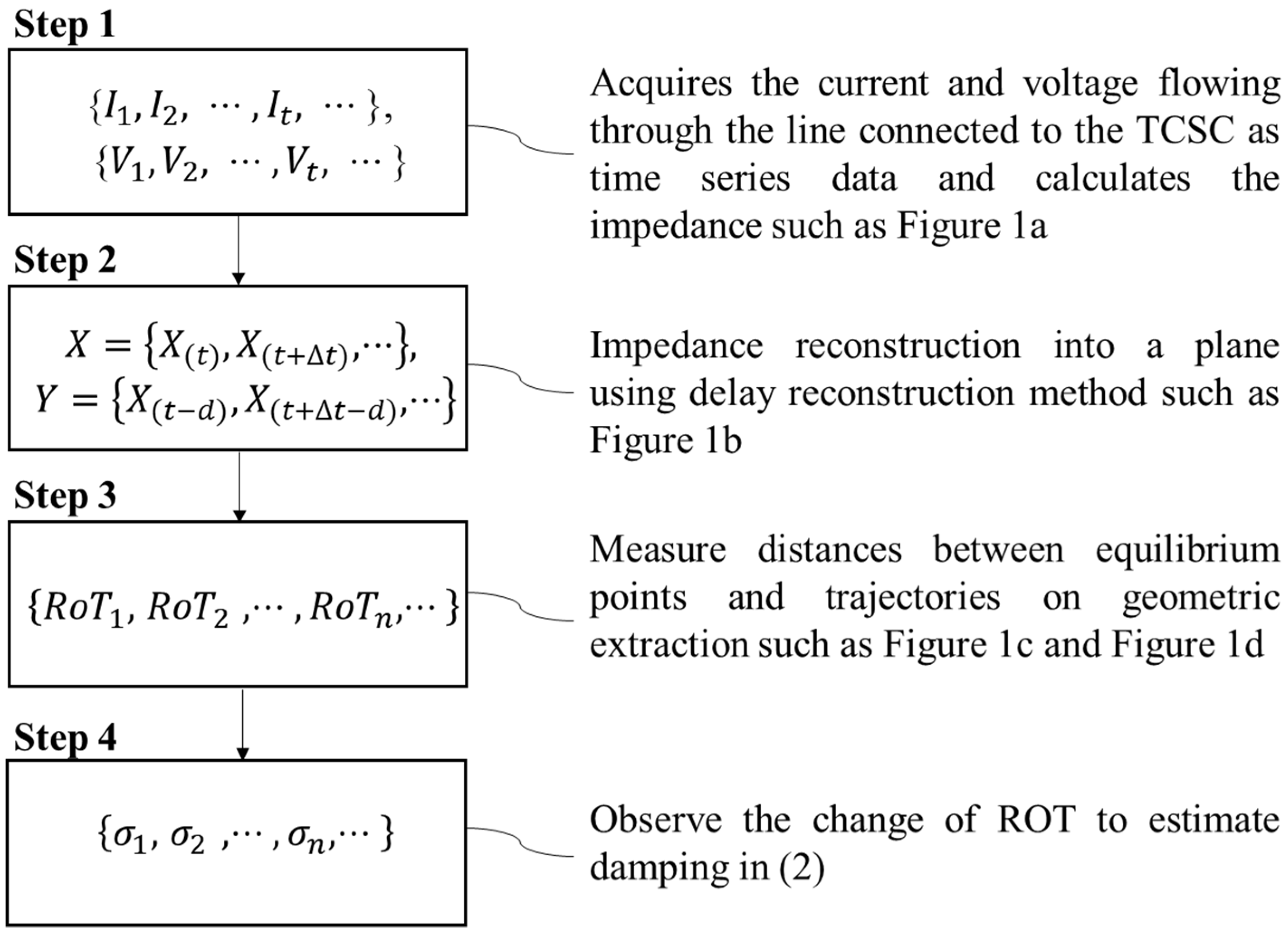
The magnitude of the active power flowing to the TCSC can be used to determine whether an SSTI has occurred based on the increased geometric extraction to the normal operating point shown in Figure 2. As the radius of trajectory (ROT) increases, the alpha of the TCSC can be controlled to avoid an SSTI. The distance between the equilibrium point and delay reconstruction is calculated as follows. The equation of nth radius of trajectory, RoTn, consist of the equilibrium point, Xeq; measured value, X(t); and delayed value, X(t − d).
R o T n = ( X e q X ( t ) ) 2 + ( X e q X ( t d ) ) 2
When oscillation occurs, the abovementioned distance increases and exceeds RoTCriter. The current damping value can be derived from σ, which is the damping ratio in (2) using the ROT. The α and φ represent coefficients and phase angles, respectively.
R o T n = α e ( σ · t + φ )

3. Mitigation Method Using Alpha Control in Real-Time

The detector identifies oscillations through the ROT. The main purpose of the real-time damping controller is to avoid the SSTI condition when oscillations are detected, owing to the impedance change in the line through the firing angle control of the TCSC.

3.1. Real-Time TCSC Impedance Calculation

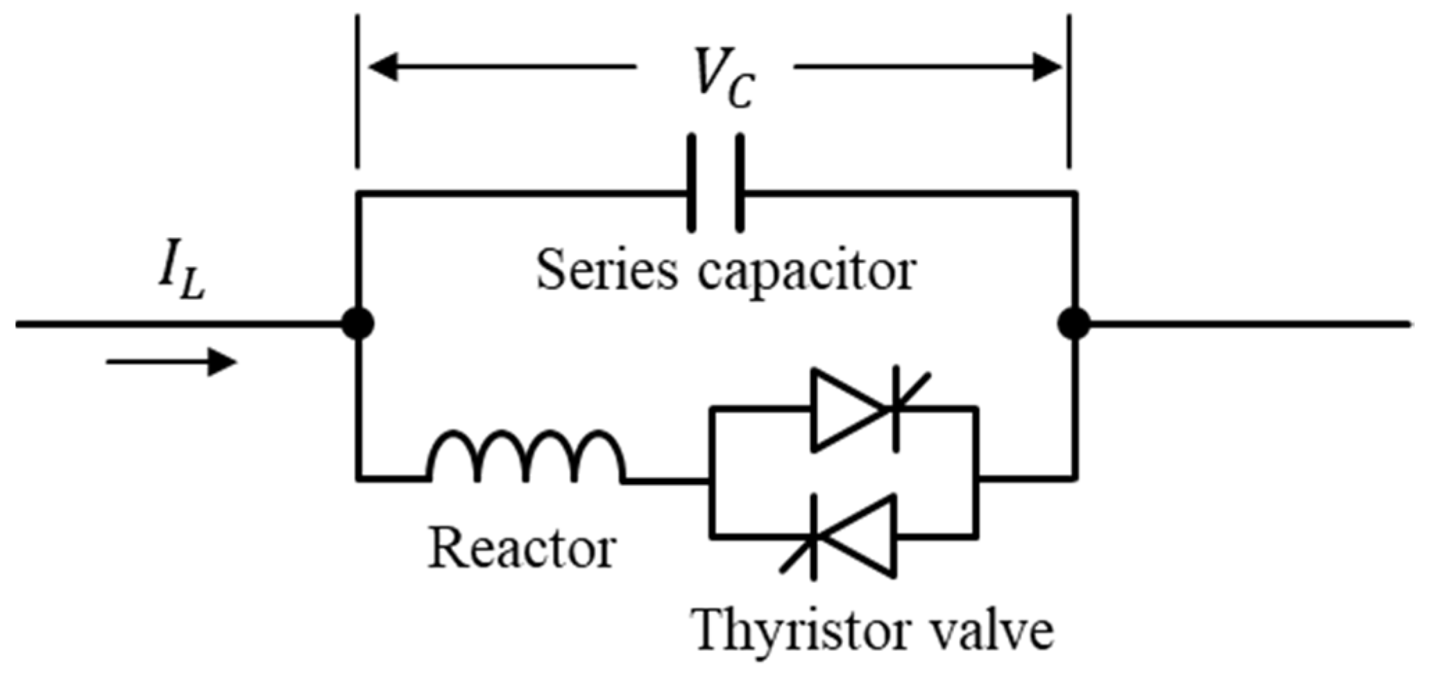
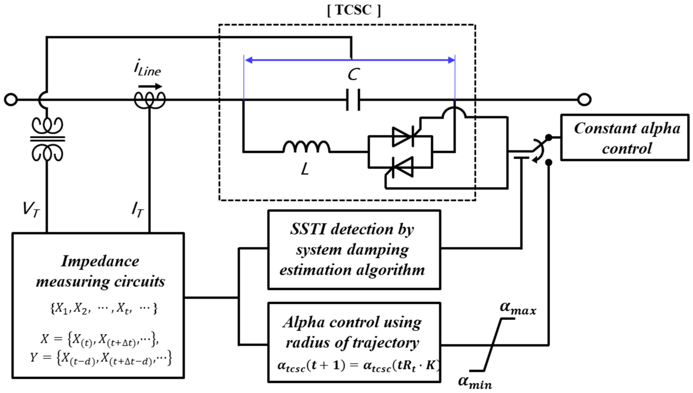
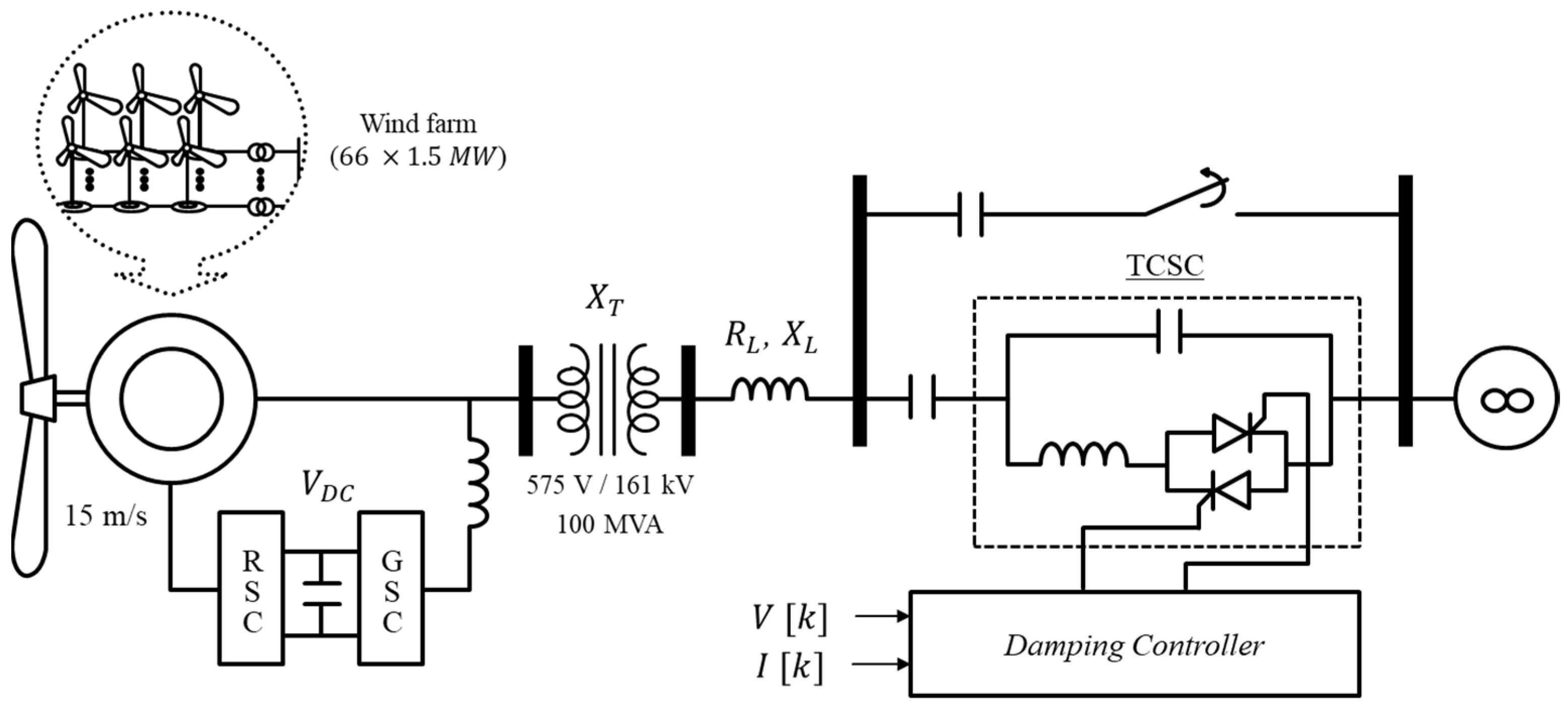
Figure 3 shows the configuration of the TCSC. The TCSC is a series compensation system wherein a thyristor-controlled reactor (TCR) and a capacitor configured in parallel are connected with the existing line. The current flowing through the reactor is controlled by adjusting the firing angle of the thyristor, which enables adjustments in the voltage across the capacitor. Assuming that the incoming and outgoing currents of same-sized series components are equal, the impedance of the TCSC can be controlled by adjusting the magnitude of the voltage shown in Figure 4.
The impedance can be calculated in real time, as expressed in (3), by using the voltage and current flowing across the TCSC [30,31]. The impedance of TCSC, XTCSC(α), consists of a fixed capacitive impedance, XC; a variable inductive impedance, XL(α); and a delay angle, α. That is,
X T C S C ( α ) = X C X L ( α ) X L ( α ) X C
X L ( α ) = X L π π 2 α s i n α , X L X L ( α )

3.2. Configuration of Geometric Feature Extraction Method Using Alpha Control

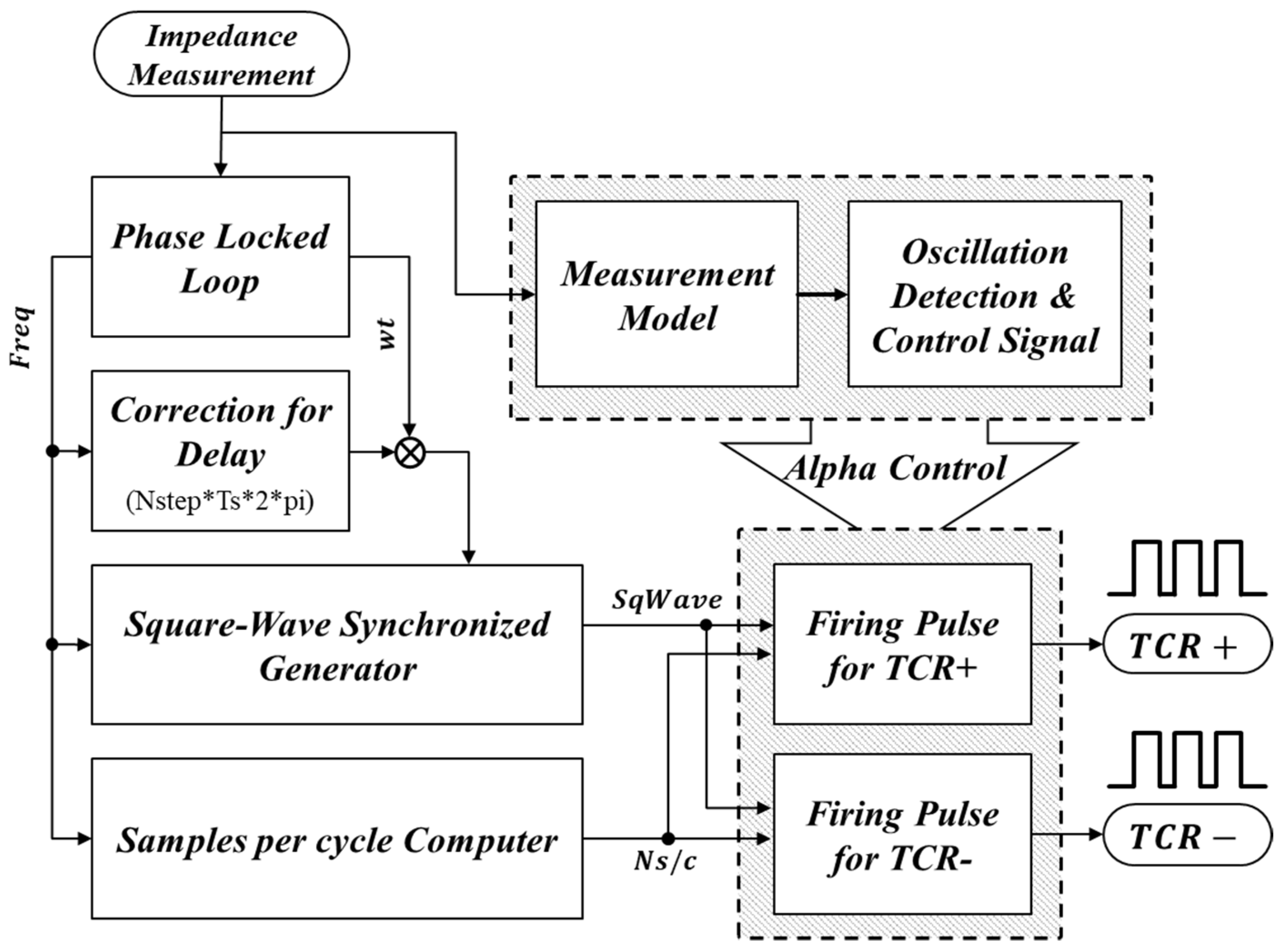
Figure 5 describes the control mode in which the TCSC changes from constant alpha control to alpha control using the ROT when an SSTI is detected.
As the ROT increases, the alpha decreases at a constant rate and is updated when the period of the trajectory traced by the delay reconstruction method passes. As the alpha decreases, the compensation level of the TCSC quickly decreases, thus preventing an interaction. At this time, as there exists a limit to physically varying the alpha, the maximum and minimum limits are calculated and added to the end of the controller. For alpha control, the TCR requires an update to match the cycle. Figure 5 shows a conceptual diagram of the sensing oscillation when the impedance is calculated, along with the control of the TCR according to a control signal.

4. Simulation Results of Case Studies

4.1. Case Study 1: Mitigation of SSTI in a DFIG Wind Farm Using TCSC
A system composed of TCSCs connected in series with a DFIG wind farm was implemented, as shown in Figure 6 and Table A1 and Table A2. The DFIG wind farm and TCSC models in case study 1 were based on general models of MATLAB. The DFIG wind farm is a DFIG aggregated model with 66 generators, each of which outputs 1.5 MW, thus providing a total output of 100 MW. The simulation was performed for 5.0 s, and an accident in a line connected in parallel with the TCSC was assumed to happen after 1.0 s. When a specific contingency occurs in a weak grid with a high compensation level, oscillation occurs, as shown in the waveform without control.
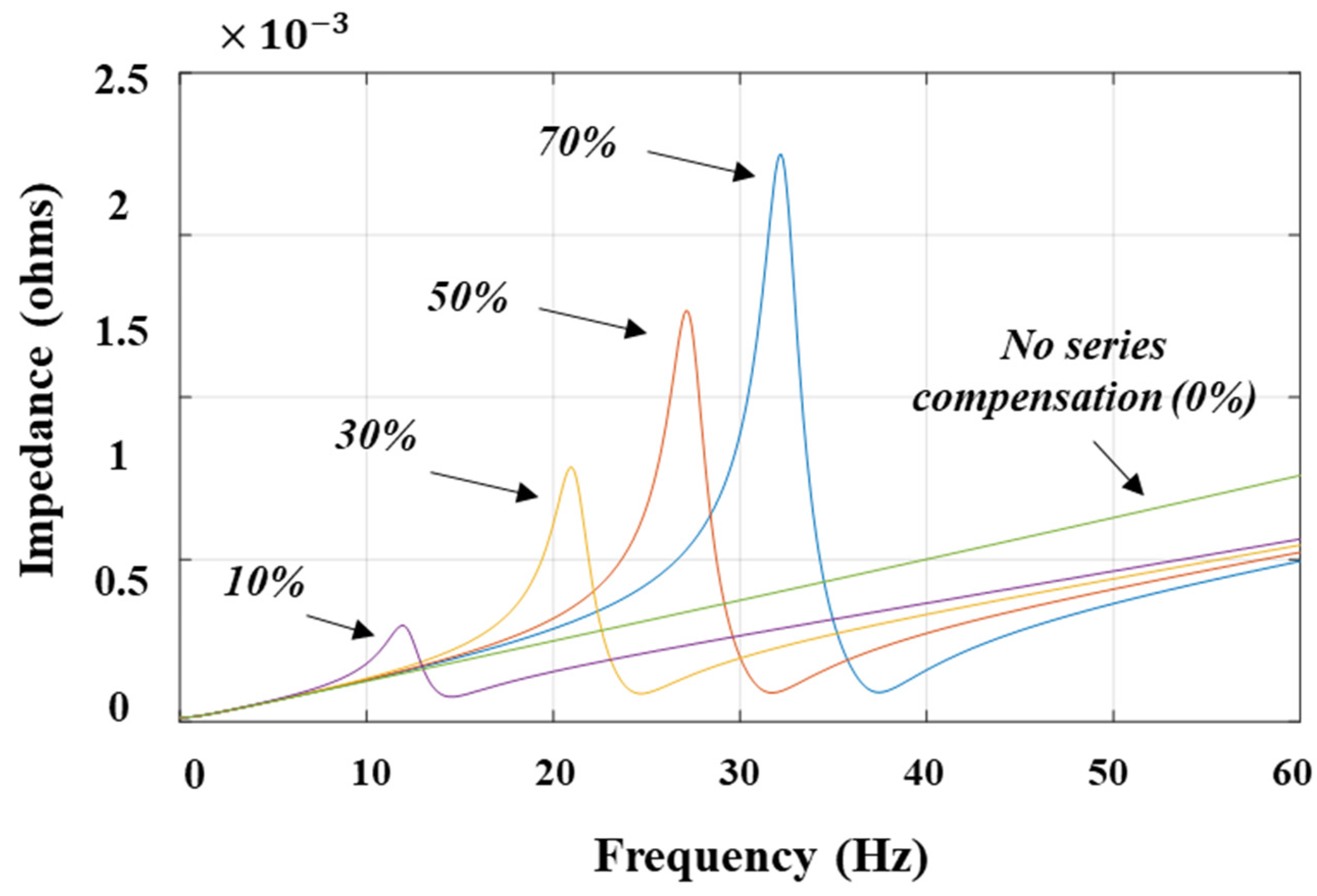
Figure 7 shows the relationship between frequency and impedance, indicating the area where resonance can occur as the series compensation increases. As seen in Figure 7, the series compensation resulted in resonance at frequencies 14.2, 24.8, 31.4, and 37.3 Hz for compensation levels of 10%, 30%, 50%, and 70%, respectively.
Figure 7. Impedance profile according to series compensation change.
Sustainability 14 16110 g007
f e = f n X c X e q
f r = f n f e
where
  • fe = subsynchronous resonant frequency;
  • fn = 60 Hz (natural frequency);
  • fr = rotor frequency;
  • Xc = series capacitor reactance;
  • Xeq = equivalent reactance of the system.
In this case, a 70% compensation level was simulated to assume the case of oscillation. Therefore, according to (5) and (6), fr was generated with approximately 22 Hz oscillation. Figure 8 shows the fast Fourier transform (FFT) analysis results. Here, fn is the natural frequency, corresponding to 60 Hz; XC is the series capacitor reactance; and Xeq is the equivalent reactance of the system. FFT is an algorithm that allows for a quick execution of a Fourier transform using periodicity, and it can analyze a signal over time by decomposing it into frequency components. The oscillation that occurs in this case is between the DFIG and the TCSC with a specific impedance state. Therefore, as shown in Figure 8, the oscillation component increased with time.
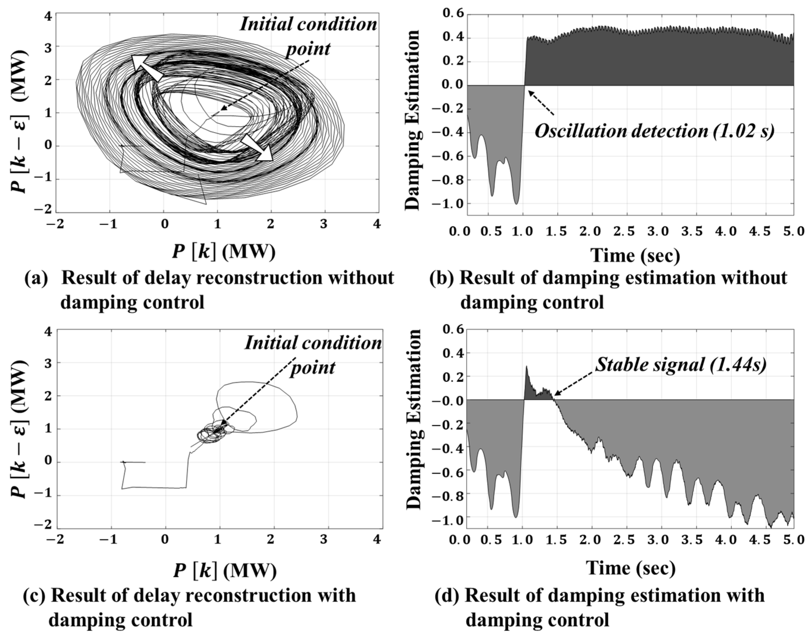
Figure 9a presents the delay reconstruction results when the system was at a compensation level of 70% and when the damping control did not operate. As oscillation occurred at the point where the equilibrium was maintained at the initial condition point, before the accident after 1.0 s, the ROT also increased. Figure 9b shows the results of the damping estimation over time.
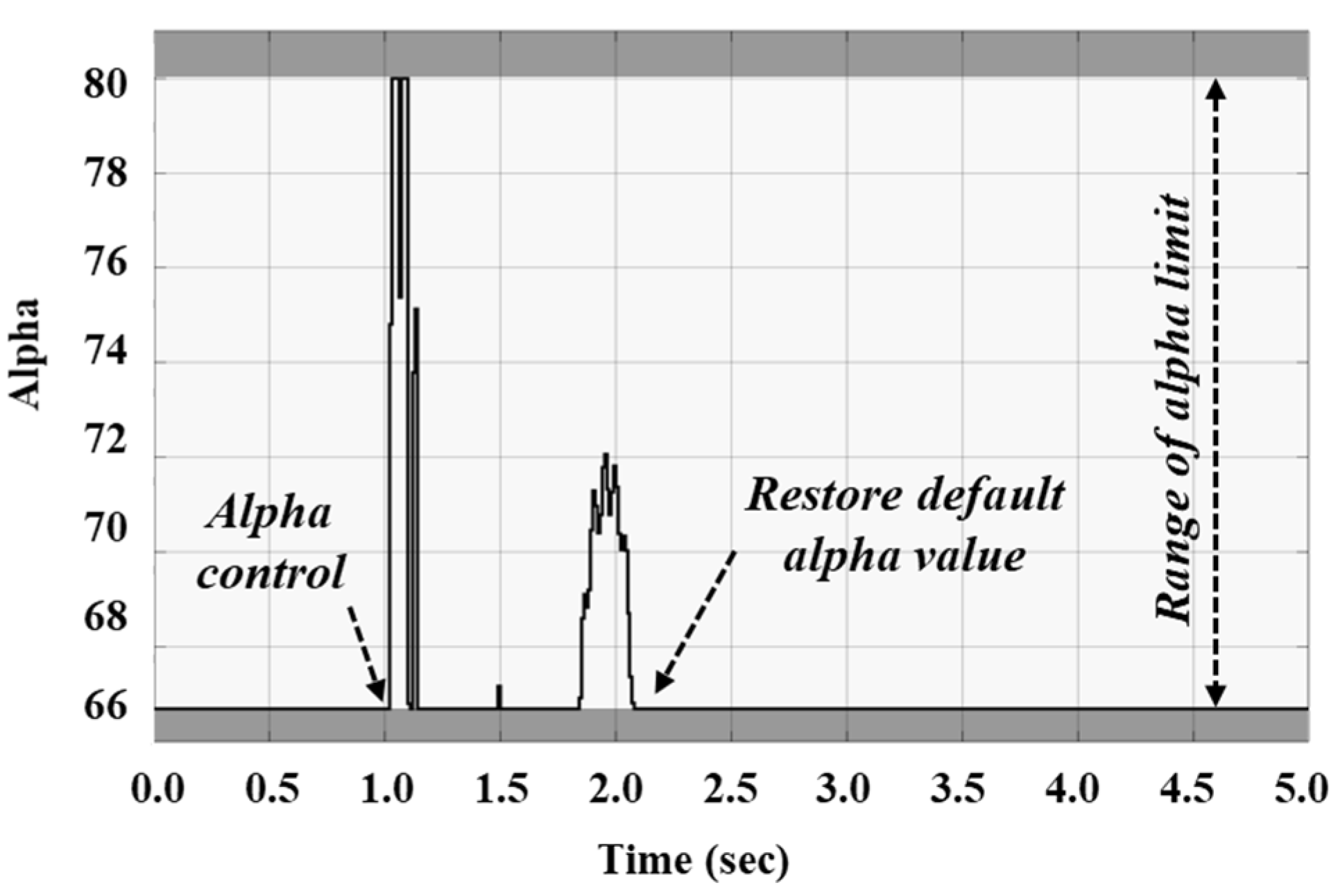
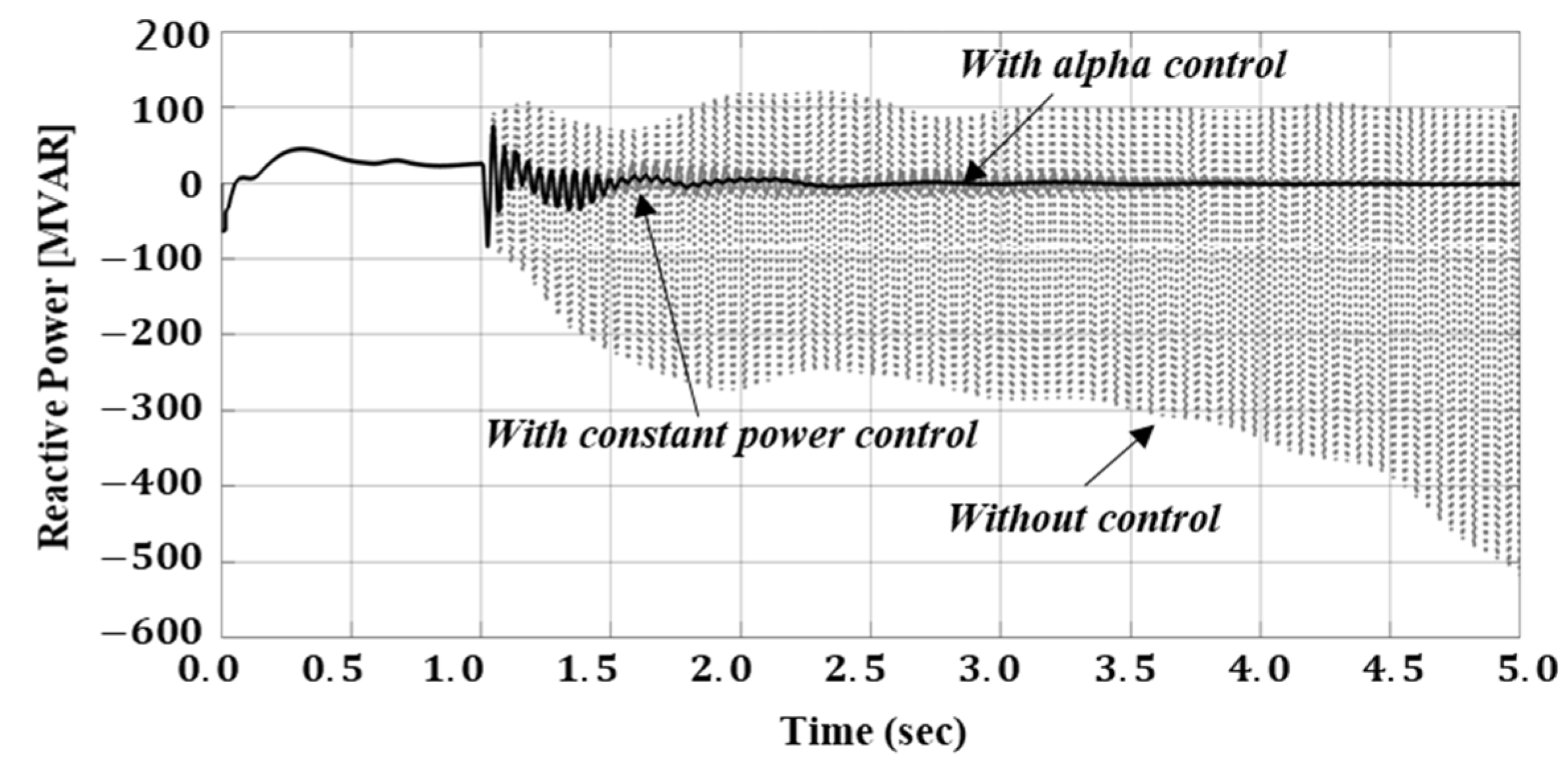
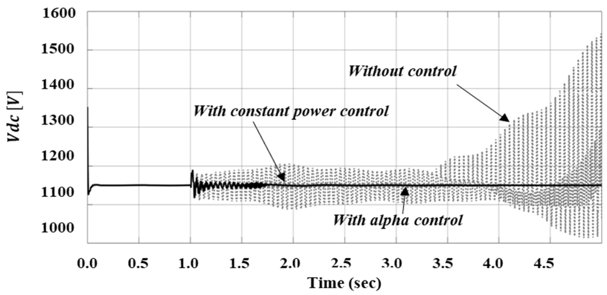
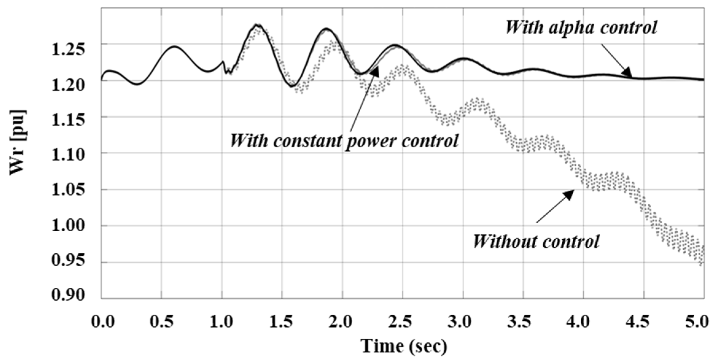
After 0.02 s from the time of the accident, the damping estimation result increased to a value exceeding 0, and the oscillation could be detected. At this time, the oscillation could be mitigated by adjusting the alpha, as shown in Figure 10. Figure 11 shows that the oscillation did not occur even if the initial default alpha value was restored after oscillation mitigation. Figure 9c,d show the results of the delay reconstruction and damping estimation when the oscillation was mitigated. Figure 11 presents the active power flowing through the TCSC. Without control, undamped oscillation occurred at a 70% compensation level. During operation, oscillation was mitigated if the alpha control was performed when the damping estimation value was higher than 0, as shown in Figure 9b. At this time, if oscillation occurred, the damping estimation value decreased below 0, as shown in Figure 9d. For the TCSC, there existed a control method to maintain the active power constant using the reference signal, Pref. However, as shown in Figure 11, the alpha control proposed herein was more effective than the constant power control. This result indicates that, when an oscillation is detected, momentary alpha control is more effective than constantly controlling the power. Moreover, as shown in Figure 10, it is explained by the actively changing magnitude of alpha for relaxation according to the degree of oscillation. Figure 12 depicts the reactive power, and Figure 13 and Figure 14 indicate Vdc and the speed of the generator. As shown in Figure 11, the oscillation was mitigated when the alpha control was performed after oscillation detection.
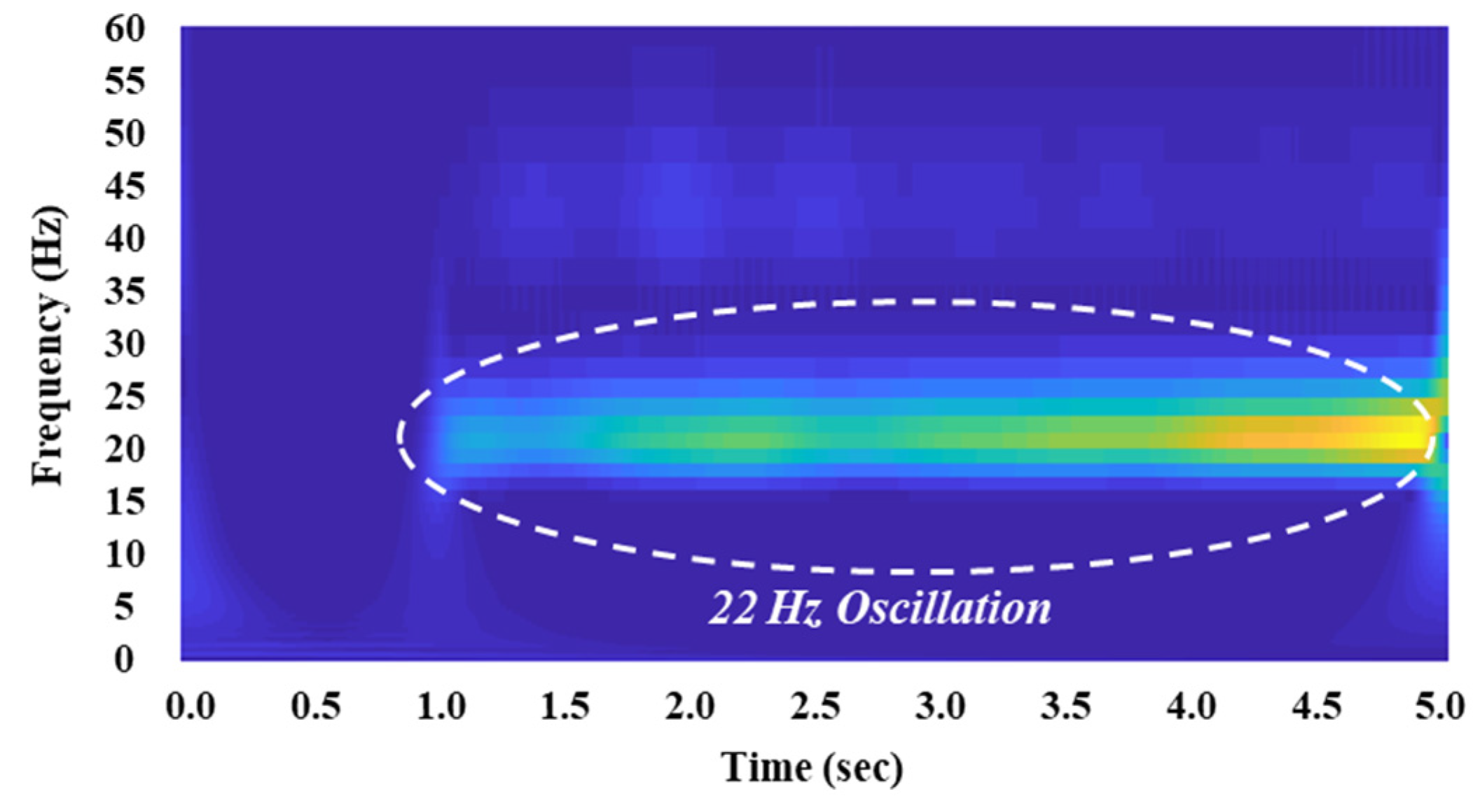
Figure 15 and Figure 16 present the results of the continuous wavelet transform (CWT) for active power. CWT can analyze frequency patterns that change over time. As shown in Figure 15, after the 1.0 s accident, an oscillation of 22 Hz occurred in the subsynchronous area (bright area). In Figure 15, the 22 Hz oscillation was mitigated using alpha control.

4.2. Case Study 2: SSTI Mitigation Using TCSC in the Korean Power System

In case study 2, unlike case 1 where a test system was used, a simulation was performed for a large power system (the Korean power system). PSCAD was used to perform the simulation by utilizing generator data with the mode frequency. For this analysis, the Korean power system data in the PSS/E format were converted into PSCAD data using E-tran. At this time, it is abbreviated as a three-level of the bus Hanul NP#2 connected to TCSC, the region of interest. The other buses were connected to the subpage and are represented by a node export symbol.
As shown in Figure 17, there existed a system that transmitted large-scale power from Area 1 to Area 2. To generate the SSTI, we assumed the N-4 contingency of the Hanul NP#2-Sintaebaek3 345 kV and Hanul NP#2-Hanul NP#1 345 kV lines. In this case, oscillation occurred between the Hanul generator and the system including the TCSC.
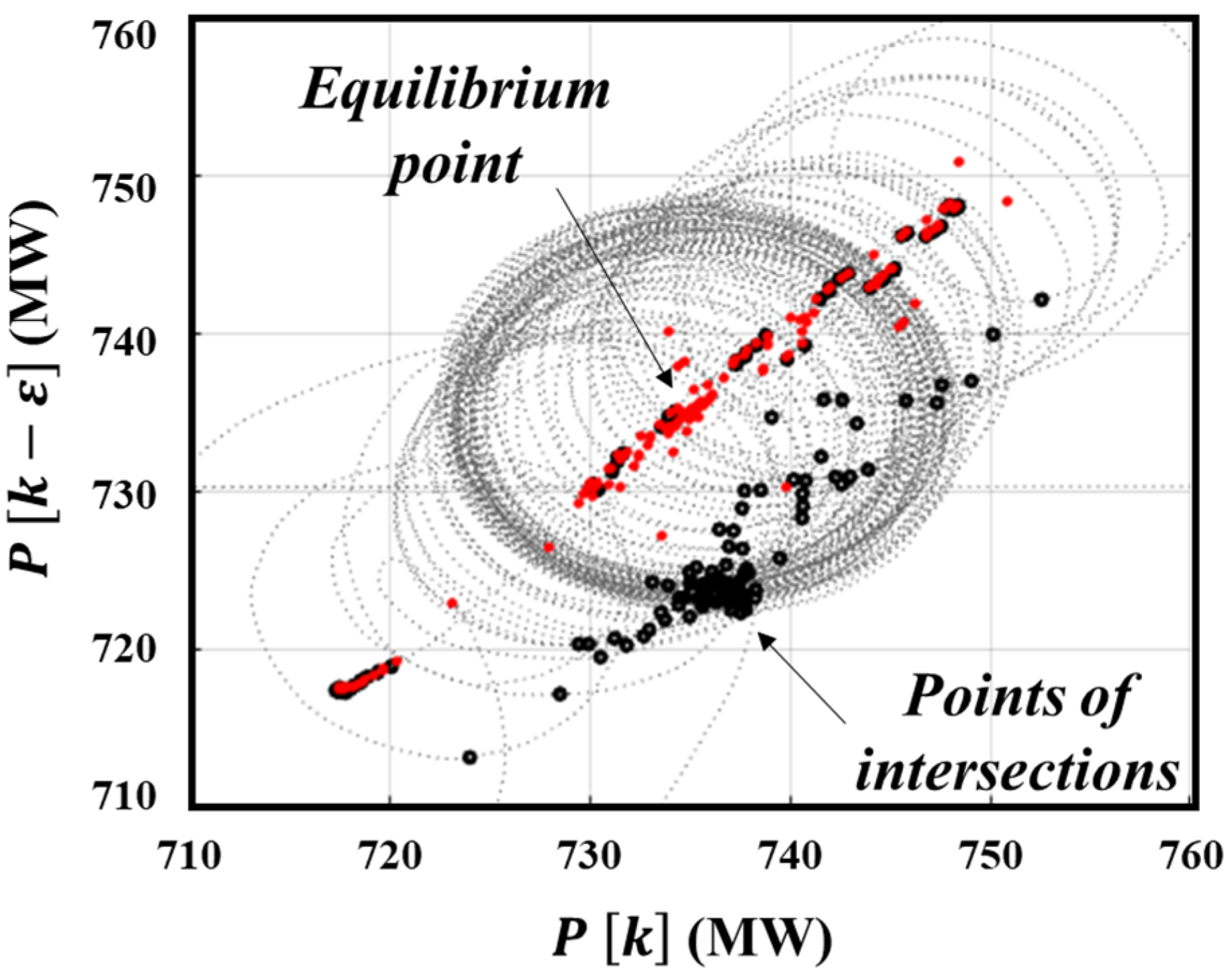
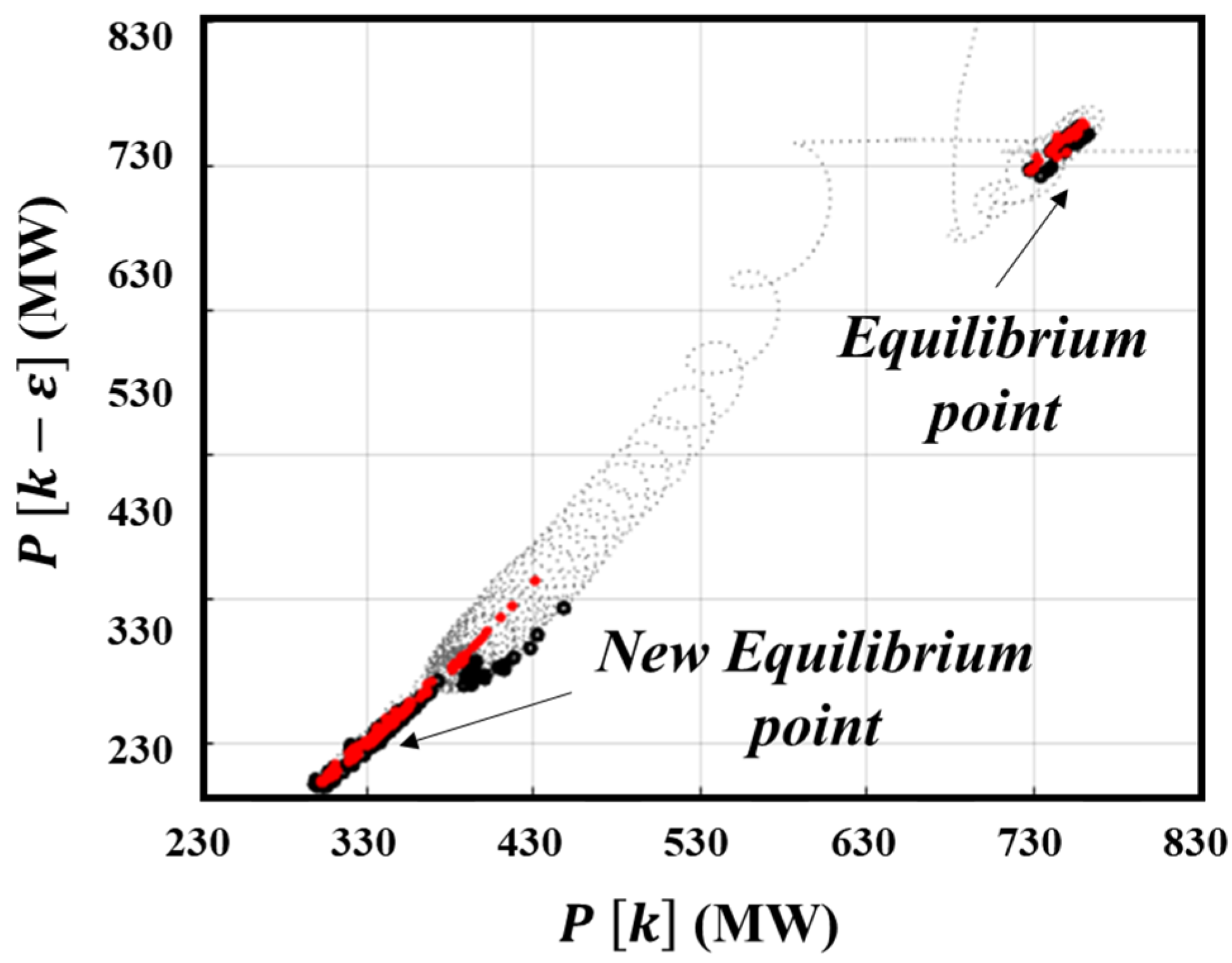
Figure 18 shows the active power flowing between Hanul NP#2 and Sinyeonju in the delay reconstruction. By expressing these data as the delay reconstruction data and calculating the points of intersection that were distant from the equilibrium point, an important quantity that depends on the current state for detecting oscillations was obtained. Figure 19 presents the value of the damping estimation obtained from the ROT between the equilibrium point and the points of intersection in Figure 18. After the fault occurred in 1.0 s, the damping value became positive in approximately 3.0 s, and an oscillation was detected.
The simulation was run for 10.0 s, and a fault occurred at 1.0 s. The active power between Hanul NP#2 and Sinyeonju fluctuated within 1.0 s, as in the case without control depicted in Figure 20. Thereafter, an oscillation of approximately 8.4 Hz occurred such as mode frequency shown in Table A3, as in the case of the waveform without control.
Figure 21 and Figure 22 show the results when damping control was applied for case study 2. Figure 21 shows that the oscillation decreased while moving to a new equilibrium point that was different from the initial equilibrium point obtained through the delay reconstruction method. Figure 22 shows the result of the damping estimation and proved that it was stable below 0 when damping control was applied.

5. Discussion

Possible methods for mitigating oscillations during operation include the identification of the cause of generator trips and mitigation through control. However, severe changes in the system, such as trips to large-scale generators, adversely affect the transient and frequency stabilities and can overburden the system operator. Therefore, in this paper, we propose an oscillation mitigation method that uses control. The biggest contribution of the proposed contents is the part that can be controlled and solved without an equipment trip due to oscillation. Figure 23 shows a conceptual diagram illustrating this strategy.
If an oscillation is detected at the operating point during normal operation, the relay of the dangerous generator that receives the protection signal is operated, and the generator trips a few seconds later. However, the strategy proposed herein is based on the mitigation of oscillations owing to the damping control of the TCSC without generator trips.
However, the controller proposed herein does not introduce a classification or mitigation method for each oscillation mode. Therefore, implementing mitigation techniques for several subsynchronous oscillations should be the subject for future research. However, the purpose of this study is to detect and mitigate oscillations using time-series data measured from the front of the TCSC, and it is not limited to a specific topology. For example, the gain of the regulator can be adjusted according to the degree of oscillation in various ways, such as controlling the governor of the generator and HVDC system, in addition to FACTS. The large-scale power system presented in our paper is a time domain simulation of the EMTDC environment to detect and mitigate oscillation in real time, and it is limited in interpretation, such as with the eigenvalue. Nevertheless, we will continue to verify it through additional reviews of wind speed changes and an analysis of the eigenvalues through future research. In addition, several studies on the mitigation of SSR using facilities such as UPFC or SSSC have been provided [32,33,34,35]. The algorithm proposed in this paper has the potential to be applied and extended in various facilities. By managing these tasks, the power system operator can benefit from efficient detection and mitigation measures for SSTI without the burden of a facility trip.

6. Conclusions

In this study, we propose a strategy to detect and mitigate oscillations by reconstructing the time-series data measured in front of the TCSC when an SSTI between the generator and FACTS devices occurs in a power system employing a TCSC. In this case, a delay reconstruction method was used to extract the dynamic features of nonlinear time-series data and implement a new phase space to detect and mitigate oscillations. The proposed controller utilizes a geometric extraction from the equilibrium point using delay reconstruction time-series data. Using this value, the oscillation can be relaxed through the alpha control of the TCSC. In this paper, we verified the mitigation of oscillation in subsynchronous regions of about 22 Hz and about 18 Hz through two study cases. Utilizing the technique proposed in this paper has the advantage of being able to control and mitigate oscillation when oscillation occurs. Therefore, these oscillation monitoring and control functions are expected to be utilized not only in TCSC but also in a large number of converter systems.

Author Contributions

Conceptualization, H.N. and B.L.; methodology, H.N.; software, H.N., H.C. and S.C.; validation, B.L.; formal analysis, H.N.; investigation, H.N.; resources, B.L.; data curation, H.N.; writing—original draft preparation, H.N.; writing—review and editing, H.N.; visualization, H.N. and H.C.; supervision, B.L.; project administration, B.L.; funding acquisition, B.L. All authors have read and agreed to the published version of the manuscript.

Funding

This work was supported by the National Research Foundation of Korea (NRF) grant funded by the Korean government (MSIT): NRF-2021R1A2C2006511; Korea Institute of Energy Technology Evaluation and Planning (KETEP) grant funded by the Korean government (MOTIE) (Establishment and demonstration of local renewable management system): 2019371010006A.

Institutional Review Board Statement

Not applicable.

Informed Consent Statement

Informed consent was obtained from all subjects involved in the study.

Data Availability Statement

Not applicable.

Acknowledgments

We would like to thank the anonymous reviewers for their comments that allowed us to further enhance the outcome of this research.

Conflicts of Interest

The authors declare no conflict of interest.

Appendix A

Table A1. DFIG Wind Turbine Parameters.
DC Bus Voltage Regulator GainsGrid-Side Converter Current Regulator Gains
KpKiKpKi
84000.835
Speed regulator gainsRotor-side converter current regulator gains
KpKiKpKi
30.60.0880.88
Q and V regulator gainsPitch compensation gains
Ki varKivoltKpKi
0.0520330
Table A2. TCSC Model Parameters.
TCR Inductance (H)TCSC Capacitance (F)
0.009497.46 × 10−6
Thyristor snubberThyristor data
R (Ohm)C (F)R (Ohm)Vf (V)
500050 × 10−90.010
Table A3. Mode Frequency of Generator Units (Hz).
Hanul power plant unit 3 and 48.4
10.9
16.1
19.9

References

  1. Rose, J. Wind Energy Systems Sub-Synchronous Oscillations: Events and Modeling; IEEE Power & Energy Society: Piscataway, NJ, USA, 2020. [Google Scholar]
  2. Shair, J.; Xie, X.; Wang, L.; Liu, W.; He, J.; Liu, H. Overview of emerging subsynchronous oscillations in practical wind power systems. Renew. Sustain. Energy Rev. 2019, 99, 159–168. [Google Scholar] [CrossRef]
  3. Sewdien, V.; Wang, X.; Rueda Torres, J.; van der Meijden, M. Critical review of mitigation solutions for SSO in modern transmission grids. Energies 2020, 13, 3449. [Google Scholar] [CrossRef]
  4. Mohale, V.; Chelliah, T.R. Sub synchronous oscillation in asynchronous generators serving to wind and hydro power systems–A Review. In Proceedings of the 2021 IEEE Industry Applications Society Annual Meeting (IAS), Vancouver, BC, Canada, 10–14 October 2021; pp. 1–7. [Google Scholar]
  5. Power System Dynamic Performance Committee. Stability Definitions and Characterization of Dynamic Behavior in Systems with High Penetration of Power Electronic Interfaced Technologies; Rep. PES-TR77; IEEE Power & Energy Society: Piscataway, NJ, USA, 2020. [Google Scholar]
  6. Kundur, P.S.; Malik, O.P. Power System Stability and Control; McGraw-Hill Education: New York, NY, USA, 2022. [Google Scholar]
  7. Ghafouri, M. Subsynchronous Resonance in DFIG-Based Wind Farms; Ecole Polytechnique: Montreal, QC, Canada, 2018. [Google Scholar]
  8. Varma, R.K.; Auddy, S.; Semsedini, Y. Mitigation of subsynchronous resonance in a series-compensated wind farm using FACTS controllers. IEEE Trans. Power Deliv. 2008, 23, 1645–1654. [Google Scholar] [CrossRef]
  9. Piyasinghe, L.; Miao, Z.; Khazaei, J.; Fan, L. Impedance model-based SSR analysis for TCSC compensated type-3 wind energy delivery systems. IEEE Trans. Sustain. Energy 2014, 6, 179–187. [Google Scholar] [CrossRef]
  10. Wang, L.; Liang, H.-R.; Prokhorov, A.V.; Mokhlis, H.; Huat, C.K. Modal control design of damping controllers for thyristor-controlled series capacitor to stabilize common-mode torsional oscillations of a series-capacitor compensated power system. IEEE Trans. Ind. Appl. 2019, 55, 2327–2336. [Google Scholar] [CrossRef]
  11. Wang, L.; Xie, X.; Jiang, Q.; Pota, H.R. Mitigation of multimodal subsynchronous resonance via controlled injection of supersynchronous and subsynchronous currents. IEEE Trans. Power Syst. 2013, 29, 1335–1344. [Google Scholar] [CrossRef]
  12. Mohammadpour, H.A.; Islam, M.M.; Santi, E.; Shin, Y.-J. SSR damping in fixed-speed wind farms using series FACTS controllers. IEEE Trans. Power Deliv. 2015, 31, 76–86. [Google Scholar] [CrossRef]
  13. Eremia, M.; Liu, C.-C.; Edris, A.-A. Advanced Solutions in Power Systems: HVDC, FACTS, and Artificial Intelligence; John Wiley & Sons: New York, NY, USA, 2016. [Google Scholar]
  14. Velpula, S.; Thirumalaivasan, R.; Janaki, M. Stability analysis on torsional interactions of turbine-generator connected with DFIG-WECS using admittance model. IEEE Trans. Power Syst. 2020, 35, 4745–4755. [Google Scholar] [CrossRef]
  15. North American Electric Reliability Corporation. Interconnection Oscillation Analysis. 2019. Available online: https://www.nerc.com/comm/PC/SMSResourcesDocuments/Interconnection_Oscillation_Analysis.pdf (accessed on 30 October 2022).
  16. Cho, H.; Oh, S.; Nam, S.; Lee, B. Non-linear dynamics based sub-synchronous resonance index by using power system measurement data. IET Gener. Transm. Distrib. 2018, 12, 4026–4033. [Google Scholar] [CrossRef]
  17. Javanmard, M.E.; Ghaderi, S.; Sangari, M.S. Integrating energy and water optimization in buildings using multi-objective mixed-integer linear programming. Sustain. Cities Soc. 2020, 62, 102409. [Google Scholar] [CrossRef]
  18. Khalilinia, H.; Venkatasubramanian, V. Subsynchronous resonance monitoring using ambient high speed sensor data. IEEE Trans. Power Syst. 2015, 31, 1073–1083. [Google Scholar] [CrossRef]
  19. Tashman, Z.; Khalilinia, H.; Venkatasubramanian, V. Multi-dimensional Fourier ringdown analysis for power systems using synchrophasors. IEEE Trans. Power Syst. 2013, 29, 731–741. [Google Scholar] [CrossRef]
  20. Salehi, F.; Matsuo, I.B.M.; Brahman, A.; Tabrizi, M.A.; Lee, W.-J. Sub-synchronous control interaction detection: A real-time application. IEEE Trans. Power Deliv. 2019, 35, 106–116. [Google Scholar] [CrossRef]
  21. Rezaei, S. Behavior of Protective Relays During Subsynchronous Resonance in Transmission Line and Adaptation of Generator Out-of-Step Protection. IEEE Trans. Ind. Appl. 2019, 55, 5687–5698. [Google Scholar] [CrossRef]
  22. Xie, X.; Liu, H.; Liu, H.; Jiang, Q. A two-level SSR protection system and its application at the Shangdu Power Plant. Int. J. Electr. Power Energy Syst. 2015, 64, 1229–1236. [Google Scholar] [CrossRef]
  23. Gong, Y.; Xue, Y. Subsynchronous Oscillation Relay. U.S. Patent 9,806,690, 31 October 2017. [Google Scholar]
  24. Mahish, P.; Pradhan, A.K. Mitigating subsynchronous resonance using synchrophasor data based control of wind farms. IEEE Trans. Power Deliv. 2019, 35, 364–376. [Google Scholar] [CrossRef]
  25. Zhao, L.; Matsuo, I.B.; Salehi, F.; Zhou, Y.; Lee, W.-J. Development of a real-time web-based power monitoring system for the substation of petrochemical facilities. IEEE Trans. Ind. Appl. 2018, 55, 43–50. [Google Scholar] [CrossRef]
  26. Fan, L.; Miao, Z. Mitigating SSR using DFIG-based wind generation. IEEE Trans. Sustain. Energy 2012, 3, 349–358. [Google Scholar] [CrossRef]
  27. Wang, S.; Xu, Z.; Wang, S. New findings on bypass damping filter in increasing subsynchronous resonance damping of series compensated system. IET Gener. Transm. Distrib. 2015, 9, 1718–1726. [Google Scholar] [CrossRef]
  28. Anderson, P.M.; Agrawal, B.L.; Van Ness, J.E. Subsynchronous Resonance in Power Systems; John Wiley & Sons: New York, NY, USA, 1999; Volume 9. [Google Scholar]
  29. Kantz, H.; Schreiber, T. Nonlinear Time Series Analysis; Cambridge University Press: Cambridge, UK, 2004; Volume 7. [Google Scholar]
  30. Hingoranl, N.G. Understanding Facts; John Wiley & Sons: New York, NY, USA, 2000. [Google Scholar]
  31. Sen, K.K.; Sen, M.L. Introduction to FACTS Controllers: Theory, Modeling, and Applications; John Wiley & Sons: New York, NY, USA, 2009. [Google Scholar]
  32. Raju, D.K.; Umre, B.S.; Junghare, A.S.; Babu, B.C. Mitigation of subsynchronous resonance with fractional-order PI based UPFC controller. Mech. Syst. Signal Process. 2017, 85, 698–715. [Google Scholar] [CrossRef]
  33. Koteswara Raju, D.; Umre, B.S.; Junghare, A.S.; Thakre, M.P.; Motamarri, R.; Somu, C. Fractional-order PI based STATCOM and UPFC controller to diminish subsynchronous resonance. SpringerPlus 2016, 5, 1599. [Google Scholar] [CrossRef] [PubMed] [Green Version]
  34. Raju, D.K.; Umre, B.S.; Junghare, A.S.; Babu, B.C. Improved control strategy for subsynchronous resonance mitigation with fractional-order pi controller. Int. J. Emerg. Electr. Power Syst. 2016, 17, 683–692. [Google Scholar] [CrossRef]
  35. Dhenuvakonda, K.R.; Singh, A.R.; Thakre, M.P.; Umre, B.S.; Kumar, A.; Bansal, R.C. Effect of SSSC-based SSR controller on the performance of distance relay and adaptive approach using synchronized measurement. Int. Trans. Electr. Energy Syst. 2018, 28, e2620. [Google Scholar] [CrossRef]
Figure 1. Structure of damping estimation and system damping estimation. (a) note: Oscillation that occurs over time; (b) note: Delay reconstruction map using measurement data; (c) note: Radius of trajectory concept diagram; (d) note: Oscillation detection method using ROT.
Sustainability 14 16110 g001
Figure 2. Procedure of system damping estimation.
Sustainability 14 16110 g002
Figure 3. Basic Structure of TCSC.
Sustainability 14 16110 g003
Figure 4. SSTI detection and control configuration.
Sustainability 14 16110 g004
Figure 5. Structure of alpha control configuration.
Sustainability 14 16110 g005
Figure 6. DFIG wind farm system including TCSC.
Sustainability 14 16110 g006
Figure 8. FFT analysis result corresponding to time change.
Sustainability 14 16110 g008
Figure 9. Results of delay reconstruction and damping estimation. (a) note: When there is no damping control, the radius of trajectory is lengthened from the initial point; (b) note: Oscillation can be detected at 1.02 s; (c) note: ROT is reduced when damping control; (d) note: Oscillation is detected, and it is possible to confirm that oscillation disappears after damping control through damping estimation.
Sustainability 14 16110 g009
Figure 10. Alpha control change results according to geometric feature extraction method.
Sustainability 14 16110 g010
Figure 11. Active power flow via alpha control of geometric feature extraction method.
Sustainability 14 16110 g011
Figure 12. Reactive power flow via alpha control of geometric feature extraction method.
Sustainability 14 16110 g012
Figure 13. Vdc of generator via alpha control of geometric feature extraction method.
Sustainability 14 16110 g013
Figure 14. Speed of generator via alpha control of geometric feature extraction method.
Sustainability 14 16110 g014
Figure 15. CWT result without alpha control.
Sustainability 14 16110 g015
Figure 16. CWT result with alpha control.
Sustainability 14 16110 g016
Figure 17. Configuration of the study area of KEPCO system.
Sustainability 14 16110 g017
Figure 18. Results of delay reconstruction without alpha control (case study 2).
Sustainability 14 16110 g018
Figure 19. Results of damping estimation without alpha control (case study 2).
Sustainability 14 16110 g019
Figure 20. Active power flow with bypass and without bypass.
Sustainability 14 16110 g020
Figure 21. Result of delay reconstruction with alpha control of geometric feature extraction method (case study 2).
Sustainability 14 16110 g021
Figure 22. Result of damping estimation with alpha control of geometric feature extraction method (case study 2).
Sustainability 14 16110 g022
Figure 23. Concept of SSTI Mitigation.
Sustainability 14 16110 g023
Publisher’s Note: MDPI stays neutral with regard to jurisdictional claims in published maps and institutional affiliations.