Article

Legs Geometry Influence on the Performance of the Thermoelectric Module

by
Abdelkader Rjafallah
,
Daniel Tudor Cotfas
* and
Petru Adrian Cotfas
Electrical Engineering and Computer Science Faculty, Transilvania University of Brasov, 500036 Brasov, Romania
*
Author to whom correspondence should be addressed.
Sustainability 2022, 14(23), 15823; https://doi.org/10.3390/su142315823
Submission received: 29 October 2022 / Revised: 21 November 2022 / Accepted: 25 November 2022 / Published: 28 November 2022

Abstract

:
The performance of the thermoelectric module highly depends on the geometry of the legs, the module area, and implicitly on the number of the pairs, besides the properties of the materials. The geometry of the legs consists of the shape, the dimensions on three axes, and whether the legs are filled or are hollow. The legs can have one hollow or more, the hole can be from the top to bottom or not. This paper studies and compares the performance of different thermoelectric modules in function of the shape: square, triangular, trapezoid, reverse trapezoid, hourglass, inverse hourglass (filled and with the hollow from the top to the bottom or not), and with different dimensions of the length and width. The simulations are performed using the COMSOL Multiphysics software, where 3D numerical models are developed and solved using the finite element method. The results are compared with others from the specialized literature for a one pair square shape. The current-voltage and power-voltage characteristics have a good matching, which proves the simulations are good and the model can be used for other shapes. A steady-state heating condition is applied to the hot side of the thermoelectric generators, while the cold side is subjected to steady state, natural convection, and forced convection heating conditions. The square shape with an internal hollow is studied first. The best performance when the length and width are 1 mm × 1 mm, 1.5 mm × 1.5 mm, and 2 mm × 2 mm is obtained for the thermoelectric generator with filled square legs. The highest maximum power is obtained for thermoelectric generator with the sizes 2 mm × 2 mm. The gain in power for the square shape in comparison with the worst value of the TEG (Inverse Hourglass for filled and Triangular for hollow) for the three dimensions considered is for those filled 199%, 202%, and 204%, respectively, and for those that are hollow 198%, 232%, and 243%, respectively. The reduction in maximum power is 5%, for the thermoelectric generator with square legs (2 mm × 2 mm) and with hollow legs, in comparison with one filled. The maximum power increases for the thermoelectric generator with square legs which have a hollow interior, in this case 2 mm × 2 mm, with 0.2% and 1% for the thermoelectric generator with sizes of 1 mm × 1 mm. Additionally, the results obtained for the square filled shape are compared with the real ones obtained for a thermoelectric generator with sizes 40 mm × 40 mm × 4 mm. The matching is very good, which confirms that the model can be used for different geometry of the thermoelectric generators in order to help the manufacturers improve their performance.

1. Introduction

The thermoelectric module and the thermoelectric panel, with modules connected in series and/or in parallel, can be suitable solutions for the production of electrical energy, either alone [1] or in tandem with photovoltaic cells, thermally connected or separate using a beam splitter [2].
There are a lot of applications for thermoelectric modules. They can be used with very good results to recover the thermal energy from vehicles’ exhaust [3], furnaces, nuclear reactors of the spatial devices [4], photovoltaic cells or panels in natural sunlight [5] or in concentrated light [6], and every system which dissipates and wastes heat in the environment.
The main advantage of the thermoelectric module is that it can produce green electrical energy from waste energy, but it has other advantages, such as: it does not have a moving part [7], which leads to a low maintenance cost and long working life [8] which is important for the applications and investment. It is also feasible for miniaturization and there are different materials which allow for covering the entire interval of temperature from 30 °C to over 1000 °C. The thermoelectric generators can be fabricated using organic materials which have the big advantage that they can be used for human applications [9]. They can be flexible, being also non-toxic, light in weight, and their mechanical performance is good [9].
The main disadvantage is the low efficiency. This issue of the thermoelectric generators, TEG, which is in close connection with the figure of merit, ZT, has to be solved. There are three groups of TEGs, as a function of the work temperature: first up to 250–300 °C; the second up to 600 °C; and the third up to 1000 °C. The ZT values for the representative TEG for each group are: 0.92 for Bi2Te3; 1 for PbTe; and 1.6 for SiGe [10]. The ZT can be enhanced if the process to develop thermoelectric generators based on Bi2Te3 is improved and some materials are added [11]. In this case, the ZT can be higher than 1. The second way to improve efficiency is to optimize the operation of the TEG. In this sense, it is important to increase the temperature difference between the hot and cold sides [12], to improve the thermal contacts between the cold side of TEG and the heat sink [5], and to increase the radiation absorption on the hot side. The geometry optimization of the thermoelectric generators is the other way to improve the efficiency. The commercial TEG modules have different areas, heights, shapes of the legs, and numbers of the NP pairs (an NP pair is formatted with one leg by n-type thermoelectric material and one leg by p-type thermoelectric material which are electrically connected in series), and the base material is Bi2Te3 used at a temperature of up to 250 °C. The bismuth telluride has a good performance at low temperatures. The n-type of bismuth telluride has a small ZT, and a low Seebeck coefficient at elevated temperatures [13]. These two can be enhanced using dopant additions, tellurium vacancies, and other methods [14]. There are some methods to improve the performance of the p-type thermoelectric material, among which optimizing carrier concentration and decreasing bipolar thermal conductivity [13]. Bi2Te3 n-type materials have a higher power factor, mobility parameter, thermoelectric quality factor than p-type materials [15]. The lattice thermal conductivity and the bandgap are the same. The Seebeck coefficient for both n- and p-type materials is almost isotropic [16].
The number of the NP pairs for a constant area 4 cm × 4 cm depends on the cross-section legs. The geometry of the legs influences the performance of the TEG module in the following way: if the length of the leg increases, the thermal resistance and the electrical resistance increase [17]; if the cross-section legs increase then the thermal resistance decreases; the open circuit thermal voltage generated the TEG with asymmetrical legs is higher than the one generated by the TEG with symmetrical legs [18]. The shape of the commercial TEG module is parallelepipedal, but modules with different shapes are developed for particular applications, such as circular TEGs for vehicle exhaust [19], or sintered ring-shaped thermoelectric legs for pipes [20].
Sisik and LeBlanc studied the impact of nine leg shapes on the temperature and electrical potential: rectangular; trapezoid; reverse trapezoid; hourglass; inverse hourglass; Y; reverse Y; hollow rectangular; and multi-hollow rectangular. They found that the hourglass leg shape had the best generated power and the highest electrical potential, and they concluded that the coupling legs’ shape with boundary condition is very important for the TEG performance [17]. Sahin and Yilbas showed through simulation that the shape parameter of the leg (rate of change of the cross-sectional area of the legs along its height) has a critical influence on the TEG performance [21]. An increase in the shape parameter from 0 (the shape of the leg becomes trapezoidal) will lead to growth in efficiency. Mijangos et al. developed an asymmetrical shape leg-trapezoidal (with shape parameter >0) based on Bi2Te3 and compared its performance with a symmetrical one [18]. The developed thermoelectric module consists of nine pairs of legs. The dimensions of the rectangular legs are 1.7 mm × 1.7 mm × 2.1 mm and that of the pyramidal legs are the same as rectangular legs with a 10° slant angle of the pyramid. The dimensions of the alumina plates are 13 mm × 16 mm × 0.6 mm, and the dimensions of the copper contacts are 2 mm × 5 mm × 0.34 mm. The dimensions of the entire thermoelectric modules are 13 mm × 16 mm × 3.98 mm. The maximum output power given by the modules was also evaluated. For that, an identical heat flux of around Q = 4 mW/mm2 was applied, which creates a temperature gradient in the legs of ΔT = 20 °C, to both modules by applying an electrical current 90 mA to resistive heater. It was observed that an asymmetrical thermoelectric module delivers almost two times the maximum power, Pmax, as compared to a rectangular one. The module developed was compared with a TEG-FERROTEG 9501/71/040B commercial module, with 71 pairs and 22 mm × 22 mm dimensions, all under heat flux of 4 mW/mm2, which creates ΔT = 20 °C in the legs. By projection of their modules to 71 pairs, they obtained by extrapolation 2.36 mW and 3.94 mW for symmetrical and asymmetrical, respectively, against 1.5 mW given by TEG-FERROTEG 9501/71/040B [14]. The height of the legs and their number play an important role in TEG performance. Fateh et al. found that the same power per unit of TEG area can be obtained with a smaller number of shorter legs as well as a greater number of longer legs [22]. This is very important from point of view of the quantity of the materials and the cost. Thimont and LeBlanc using a simulation in COMSOL Multiphysics, studied the impact of the leg geometry on the thermal resistance and power output taking into account the leg shape, filled or hollow, and also for the layered leg. Comparing the performance of the conventional legs with layered ones it was found that: the open circuit voltage is 46% lower for the conventional legs; the internal resistance is 42% lower for the conventional legs than for the layered ones; and the peak power is 48% higher for the layered ones than the conventional legs [23]. Liu et al. proposed a new combined design with segmented materials for realizing the legs with a constant cross-sectional area. Two materials are used for the P-type leg: P1-Bi0.48Sb1.52Te3 (ZT is larger than 1.087 for the 27–127 °C temperature interval) and P2-Na0.95Pb20SbTe22 (ZT is larger than 1.078 for the 227–427 °C temperature interval). AgPb18SbTe20 is used for the N-type leg. The power generated by the segmented TEG unit with an optimum ratio (P1/ P2 = 2.5/3.5) is higher with 14.9% than one generated by the TEG unit with a P leg only Bi0.48Sb1.52Te3, and 16.6% higher than the one generated by the TEG unit with a P leg only Na0.95Pb20SbTe22. The power generated increases additionally by 4.21% if the asymmetric design is used [24]. Li et al. studied output power, energy and exergy efficiency, mechanical reliability, and cost for the following types of shape legs: square; triangular; octagonal; and circular. Their analysis shows that the triangular shape is the best from the power generation point of view and the cost per watt is lower than the other shapes [25]. Mahmoudinezhad et al. studied the photovoltaic cell/thermoelectric generator hybrid system under 39 suns concentration ratio and showed that the legs’ length increase leads to an increase in Pmax of the TEG and a decrease in Pmax of the photovoltaic cell [26]. The shorter legs of the thermoelectric generator lead to a cost reduction [27], therefore a compromise between the generated power and the costs has to be made. There are several papers that achieve the comparison between the results obtained through simulation and experiments for the performance of thermoelectric generators. The generated voltage, current, and power of the TEP1-1264-1.5 thermoelectric generator, based on Bi2Te3, in lab experiments using a heater and heat sink, are compared with those simulated, and the matching results are over 98% [28]. Memon and Tahir studied the Bi2Te3 thermoelectric generator performance in concentrated light using the Fresnel lens. The open circuit voltage and short circuit current were analyzed in function of the temperature difference which varies from 0 to 90 °C. Additionally, the maximum power was analyzed for four temperature differences, 15.2 °C, 24.4 °C, 42.4 °C, and 64.7 °C [29]. Bensafi et al. analyzed the performance of the thermoelectric generator under parabolic concentrated light for an entire year. They found that in June the energy generated is more, with results of 92.86%, than in January [30]. Sun et al. achieved a study to verify in real time the simulation through an experimental lab setup [31]. They found there was a very good matching in voltage under the 40 °C temperature difference between the simulation and real measurements. Over the 40 °C temperature difference, the difference between the simulation and measurements is larger.
The main goal of this paper is to offer an in-depth study for researchers and manufacturers of thermoelectric generators concerning the importance of the legs’ shape to obtain the best performance in electric power and from the reduction in the material. This is achieved through the following contributions:
  • The calculation of the maximum power, short circuit current, and open circuit voltage of the thermoelectric generator based on Bi2Te3 for different shapes of the leg using COMSOL Multiphysics [32]: square (the conventional leg shape); triangular; trapezoid; reverse trapezoid; hourglass; inverse hourglass; hollow square; hollow triangular; hollow trapezoid; hollow reverse trapezoid; hollow hourglass; hollow inverse hourglass;
  • The calculation of the maximum power, short circuit current, and open circuit voltage of the thermoelectric generator based on Bi2Te3 for the first time for a square shape with internal hollow to reduce the material and thus implicitly the costs of the TEG;
  • The calculation of the maximum power and short circuit current of the thermoelectric generator based on Bi2Te3 for different difference of the temperature—the hot side is in a steady-state heating condition while the cold side is subjected to steady state, natural convection, and forced convection heating conditions;
  • A comparison of the generated maximum power by the thermoelectric generator, based on Bi2Te3 with sizes of 4 cm × 4 cm when the length and width of the legs varies from 1 mm × 1 mm to 1.5 mm × 1.5 mm and 2 mm × 2 mm, which leads to varying the pitch–the distance between legs;
  • A comparison between the results obtained for the maximum power generated by the rectangular conventional thermoelectric generator with the COMSOL Multiphysics and one in real circumstances under illumination with sunlight.

2. Materials and Methods

Different shape legs were taken into account to analyze the open circuit voltage, Voc, short circuit current, Isc, and maximum power of the thermoelectric module. Firstly, the COMSOL Multiphysics was used to simulate the behavior of the thermoelectric generator and then a comparison between the results obtained through simulation and ones obtained experimentally was made for a square conventional thermoelectric generator based on Bi2Te3.
The first step was to consider in COMSOL Multiphysics an element of TEG, which consists of an NP pair from Bi2Te3, to simulate the behavior and compare the results with the ones from the specialized literature. The second step was to consider in COMSOL Multiphysics a Bi2Te3 thermoelectric module with sizes 4 cm × 4 cm × 4 mm. The number of the NP pairs was 128 (Figure 1). The length and width of the leg was at the beginning 1 mm × 1 mm, then 1.5 mm × 1.5 mm, and 2 mm × 2 mm. The comparison between the results for these three scenarios is made in terms of Pmax, Isc, and Voc to choose the best solution. Firstly, all of these are made for uniform temperature distribution on both sides of the thermoelectric generator module. Secondly, a study is completed when the hot side is in a steady-state heating condition and the cold side can be in steady state, natural convection, and forced convection heating conditions.
The equations used in COMSOL Multiphysics simulation based on finite element method are [33]:
  • for heat transfer in solids Equations (1) and (2):
ρ C p u T + q = Q + Q t
where is the density of the materials; Cp represents the specific heat, u velocity; Q is heat source; Qt is thermoelastic effects; q is heat flux in conduction; and T represents the temperature [34]:
q = k T + JST
where k represents thermal conductivity; J is the induced electric current density; and S represents the Seebeck coefficient.
  • for electric currents Equations (3)–(5):
J = Q j
J = σ E + J e
E = V
where Qj is the current source; σ represents electrical conductivity; Je is the external current density; E represents the electric field; and V is the electric potential.
  • for thermoelectric effects Equations (6)–(8):
q p = P J
P = S T
J e = σ S T
where qp is the Peltier heat or power; P is the Peltier coefficient.
The open circuit voltage generated by the thermoelectric generator when a temperature difference between the hot and cold sides is present is given by [35]:
V o c = S T
where Voc represents the open circuit voltage.
The power generated by the thermoelectric generator when a load resistor is connected to the TEG, is given by:
P o u t = S T R L + R i n 2 R L
where RL is the external load resistance, Rin is the TEG’s internal resistance. The maximum power generated by TEG is obtained when RL = Rin.
The heat flow at the hot side of the TEG is given as [36,37]:
q i n = k T + S I T h 1 2 I 2 R
where Th represents the hot side temperature of TEG; and I is the electric current.
The experimental measurements for the rectangular conventional thermoelectric generator based on Bi2Te3 are made in concentrated sunlight using the facilities of the IMDEA Energy Institute-solar tower and five heliostats [38]. The current voltage characteristic is used to analyze the performance of the thermoelectric generator. The temperature of the hot and cold sides of the thermoelectric generator is measured using five K thermocouples, two of them on the hot side and three of them on the cold side. The measurement system to measure and analyze the current voltage characteristics and temperature are described by Mahmoudinezhad et al. [2].

3. Results and Discussion

3.1. Simulation

The aim is to study the impact of leg geometry on the electrical power harvested by thermoelectric modules, so twelve different leg shapes were selected as illustrated in Figure 2. The first six are filled and the other six are hollow.
The hole represents a way to reduce the material and the cross-sectional area within the same width × length footprint of each leg shape. The hollow domains in different leg shapes result in radiative heat transfer between the interior surfaces of the leg.
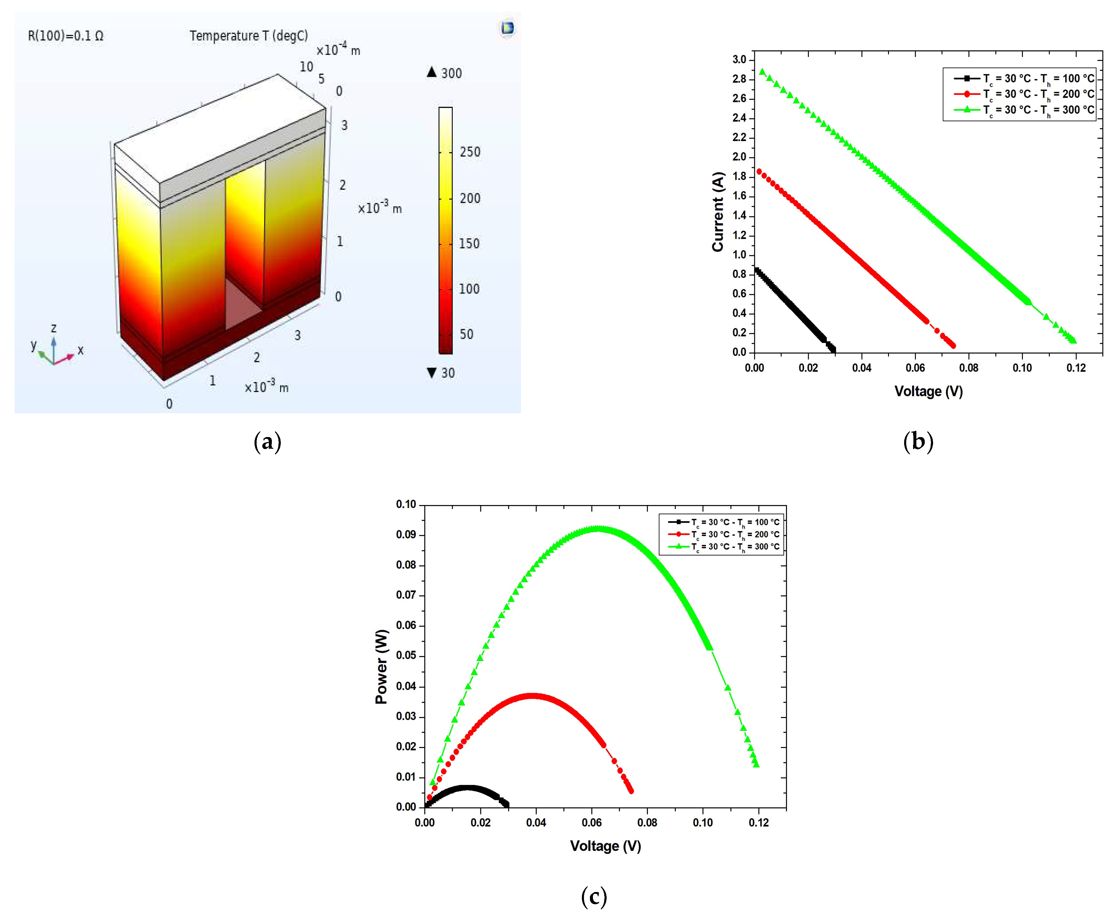
One PN pair was used to verify if the model used is corrected. The results obtained, see Figure 3, matched very well those from specialized literature, see Table 1 [33].
Table 1 present the values for maximum power Pmax, short circuit current Isc, and open circuit voltage Voc, for three temperature differences (between the hot and cold sides of TEG).
Table 2 presents the geometric dimensions, used in the simulation, for TEGs with three different cross-sectional areas regardless of the shape of the legs.
The bismuth telluride material was chosen for the TEG simulations at low temperatures (below 250°). This material has a long operation history in non-commercial and commercial thermoelectric modules. It was chosen for the TEG simulations at low temperatures because it is the standard thermoelectric material and has the highest figure of merit at this temperature range. Additionally, it is the material found in the majority of commercial thermoelectric modules.
The temperature-dependent properties for Bi2Te3 were used in the model; these correspond to the material properties in the COMSOL Multiphysics materials library [39] and are shown below in Table 3 [40].
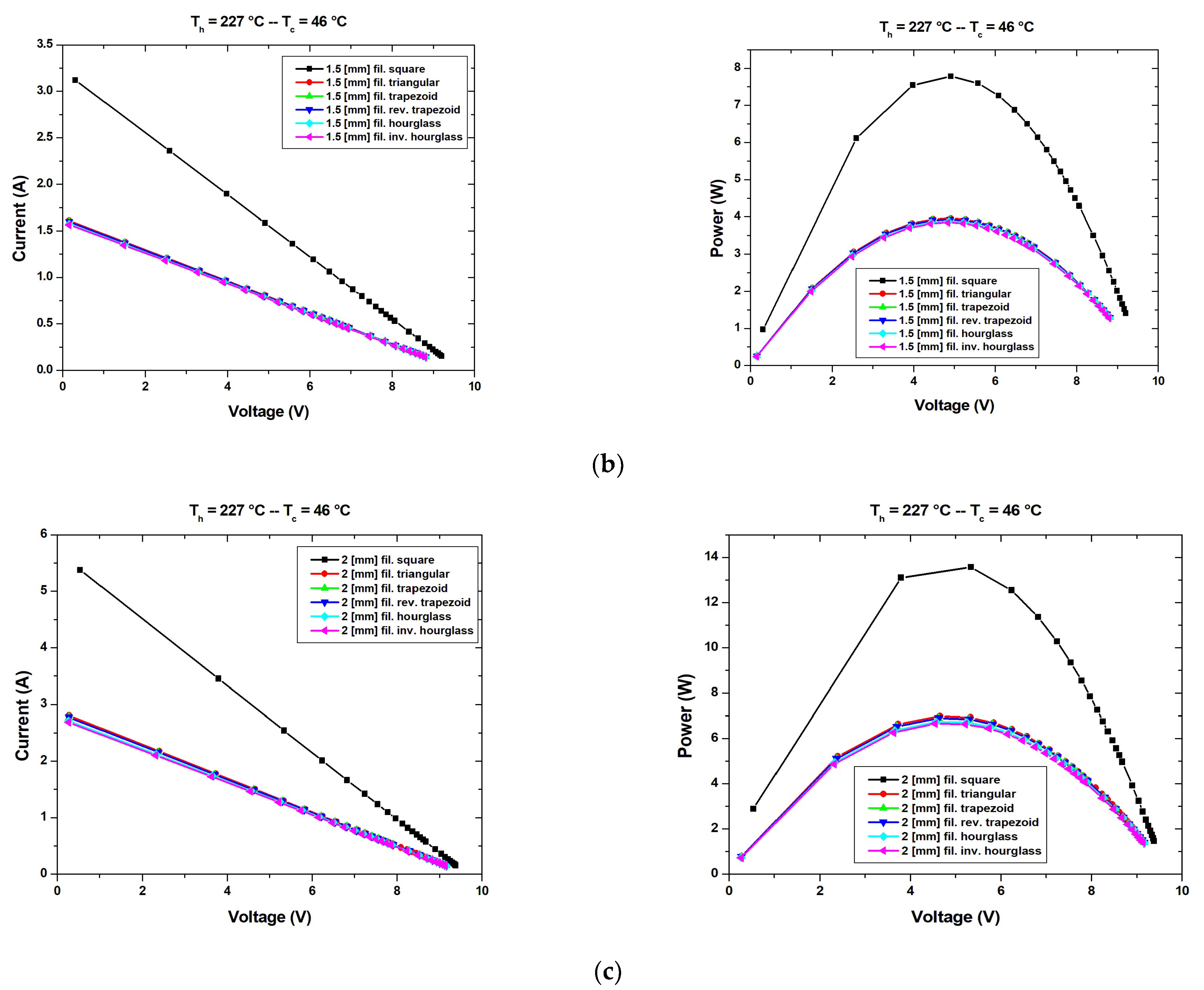
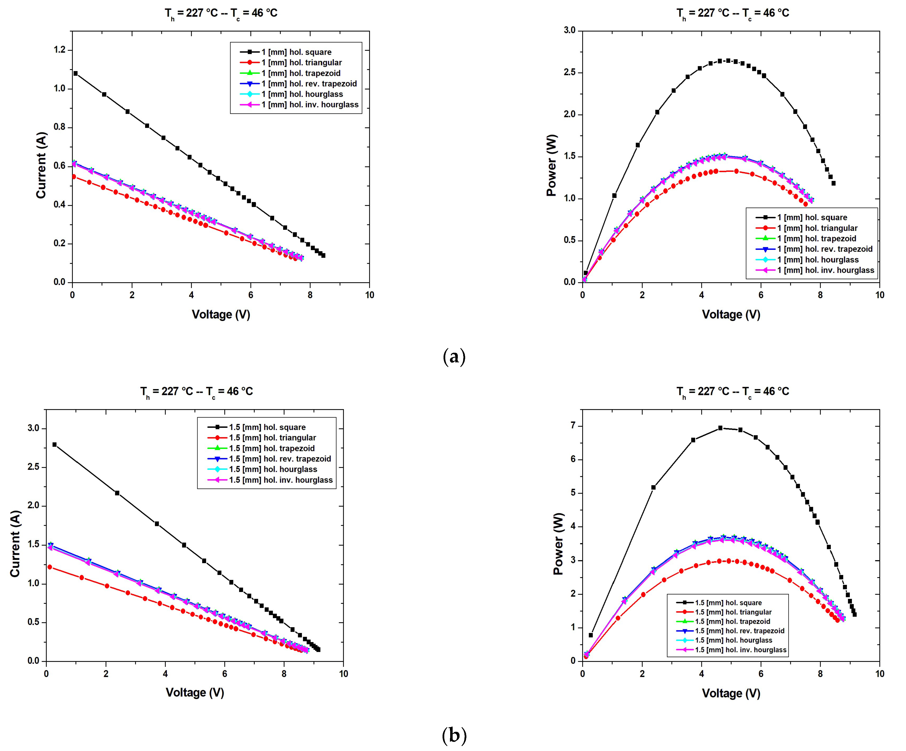
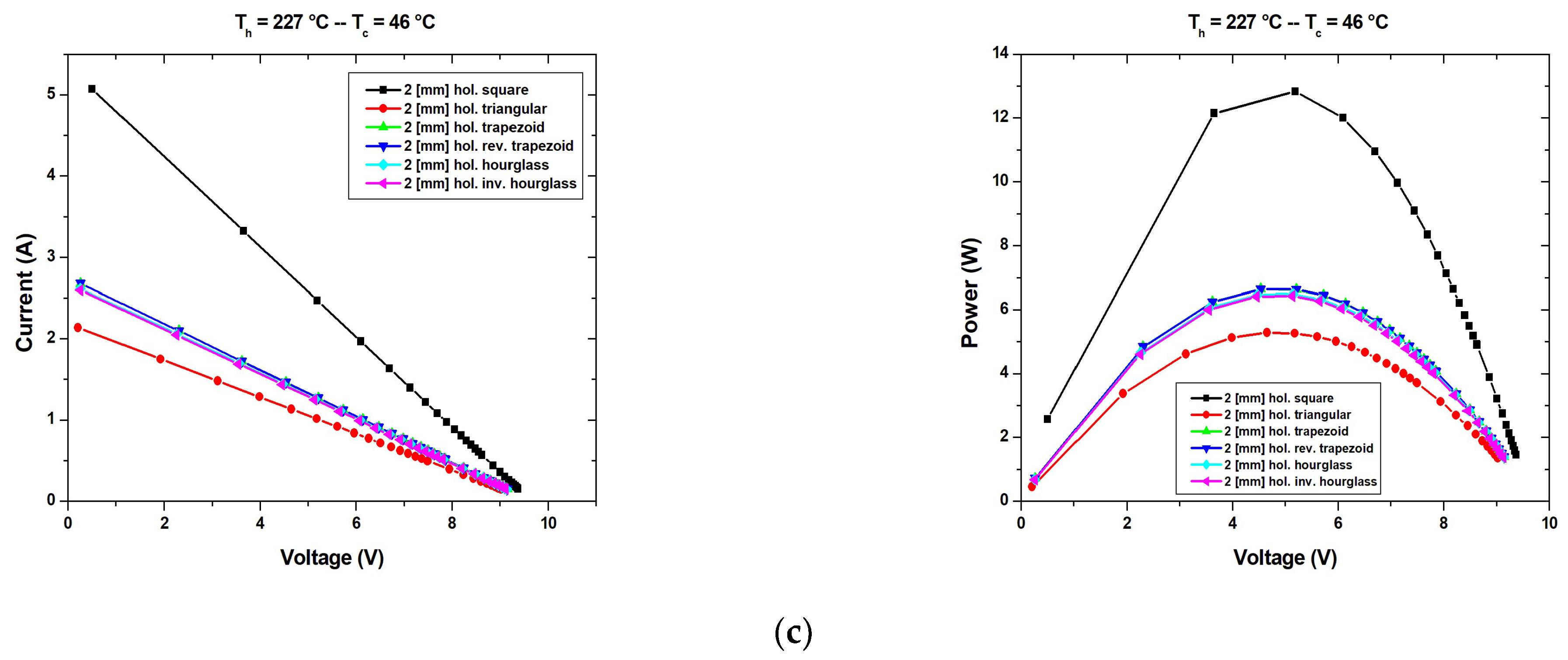
The current voltage (I-V) and power voltage (P-V) characteristics are calculated using the COMSOL Multiphysics for all TEG modules considered under steady-state heating condition, for filled legs (Figure 4) and for hollow legs (Figure 5). The short circuit current, open circuit voltage, and maximum power are extracted to compare all three scenarios based on length and width. These results are presented in Table 4 for filled legs and in Table 5 for hollow legs. The temperature of the TEG hot side is Th = 227 °C and for the cold side Tc = 46 °C.
By analyzing the results, it can be observed that the open circuit voltage varies very little for all scenarios and the values are comparable for all shape types considered in this study. This shows that the open circuit voltage is influenced very much by the shape of the legs and the pitch. For example, the variation of the open circuit voltage for the square shape-filled function of the variation with pitch is 0.3%. The open circuit voltage decreases with the decreases in the pitch (increases in the surface of the legs). The highest value is obtained for both hourglass shapes: filled and hollow. The behavior of the short circuit current is inverse in comparison with the open circuit voltage; thus, it increases with the decrease in the pitch. The maximum power has the same behavior as the short circuit current. The comparison between the maximum power generated by the TEGs in the three scenarios shows that the highest value is obtained for the last scenario when the pitch is the lowest and the surface of the legs is the highest. Consequently, to obtain the highest maximum power generated by the thermoelectric generator, it is necessary that the legs have the highest surface, but this leads to high costs. The manufacturers have to find the best solution, making an effective compromise between the costs and the efficiency of the TEG. The maximum power increases proportionally with the surface of the legs (Table 4). By comparing the P-V characteristics and maximum power in function of the shape of the legs, it is observed that the best solution is the square shape. The maximum power generated by the TEG with the square shape of the legs is almost double that of the other TEGs.
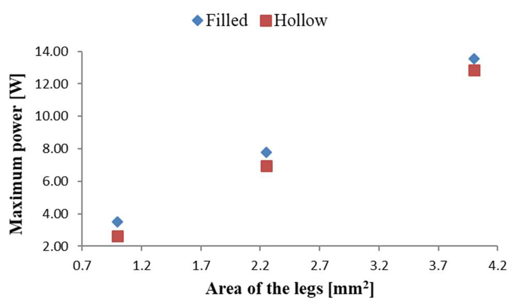
Figure 6 shows the comparison between the maximum power generated by the TEG in all three scenarios: when the shape of the legs is square, they are filled or hollow. The maximum power is lower when the legs are hollow. The losses vary from 24% in the first scenario to 10.7% in the second, and in the third scenario the losses are only 5%, which proves that this can be a good solution for reduction in materials and implicitly for the cost. The surface of the hollow is the same for all three scenarios.
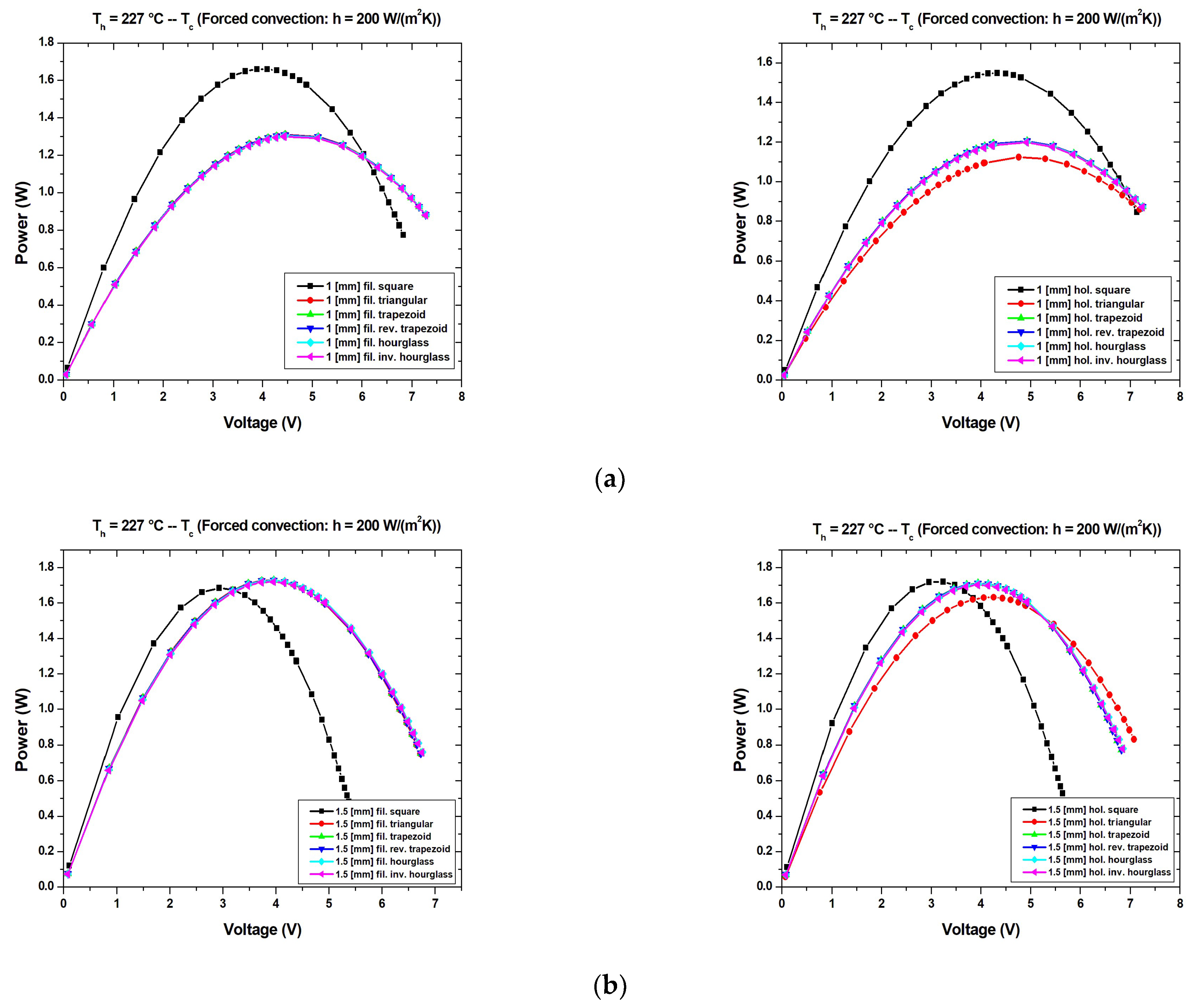
The behavior of all twelve thermoelectric modules is studied when the hot side is kept at 227 °C and the cold side is cooled using natural convection and forced convection for two values 20 W/(m2K) and 200 W/(m2K). The P-V characteristics are presented in Figure 7 for natural convection, Figure 8 for forced convection-20 W/(m2K), and Figure 9 for forced convection-200 W/(m2K). In the case of the natural convection, and the forced convection-20 W/(m2K) the maximum power generated by TEGs with the square shape of the legs is the lowest for all three scenarios considered.
The temperature difference between the hot and cold side of the TEG greatly decreases in the natural convection of the cold side, see Table 5 and Table 6. It is 7 °C for TEGs with square legs that are both filled and hollow, and 6 °C in the case of hollow, hourglass legs hollow, all for the third scenario. The highest temperature difference is obtained for the TEG with filled triangular legs and it is 44 °C. The maximum power decreases when the surface of the legs increases (the pitch decreases). This behavior is inverse in comparison with the case when the temperature is maintained as constant on both sides of the TEG. The main cause is the decrease in the temperature difference when the surface of the legs decreases. An improvement can be observed in maximum power generated when the TEGs have the hollow legs, by analyzing Table 6 and Table 7. The best are the TEGs with hollow legs from the first scenario. It can be concluded that for the small temperature difference between the hot and cold side, it is better to use TEGs from the first scenario with hollow legs.
The same behavior is in the case of forced convection-20 W/(m2K), see Table 8 and Table 9. The temperature difference is higher than in the previous case due to the better cooling of the cool side of the TEG. The best results for the maximum power generated are obtained for the TEG with an hourglass shape in the case of the filled legs and TEG with triangular shape in the case of the hollow legs.
In the case of forced convection: h = 200 W/(m2K) of the cold side, the behavior of the TEGs resembles the one when the temperature was constant for both sides of the TEGs, see Table 10 and Table 11. The main differences are: only in the first scenario is the maximum power generated by the TEGs with square legs higher than the others; the temperature difference between the hot and cold side of TEGs is not constant; the open circuit voltage is variable and the lowest values are obtained for all cases for the TEGs with square legs, see Figure 7; the best results for the maximum power generated are not unique, triangular-shape filled and hollow, reverse trapezoidal are the best for the second scenario and hourglass filled and hollow, triangular shape are the best for the third scenario, Table 10 and Table 11.

3.2. Simulation for Leg with Internal Hollow

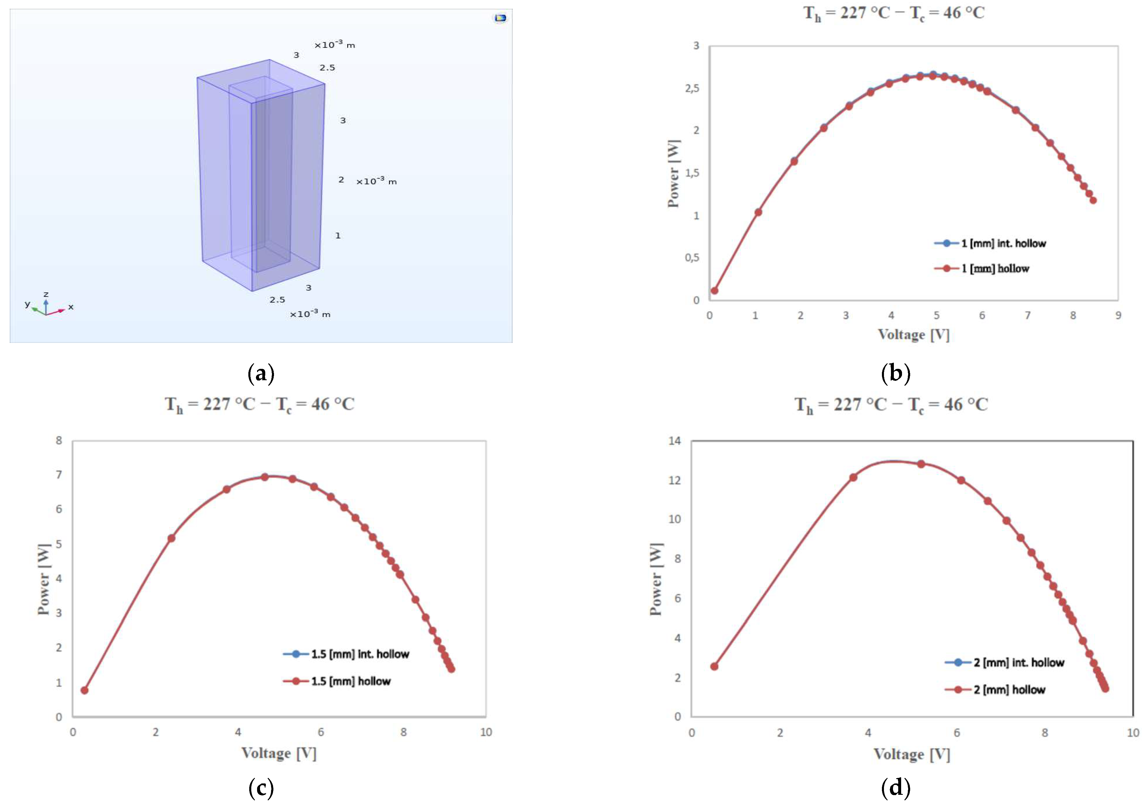
P-V characteristics are compared for TEGs with square legs with an internal hollow and that are hollow in all three scenarios considered, Figure 10. The square leg with the internal hollow has the same sizes for length and width in comparison with the hollow leg from top to bottom, but the height is smaller by 2 mm. In the top and the bottom of the leg, the squares are filled for 1 mm height.
The matching is very good, but by analyzing the results from Table 12, a little improvement is observed in the short circuit current and maximum power for the TEG with an internal hollow. The open circuit voltage is almost the same for TEGs from the same scenario. In the future, this type of hollow can be studied and the solution can be identified to optimize the TEG module from the maximum power generated and the amount of material used for the legs, to find the optimum height of the filled part and of the hollow. A problem that has to be solved is the manufacturing process.

3.3. Comparison

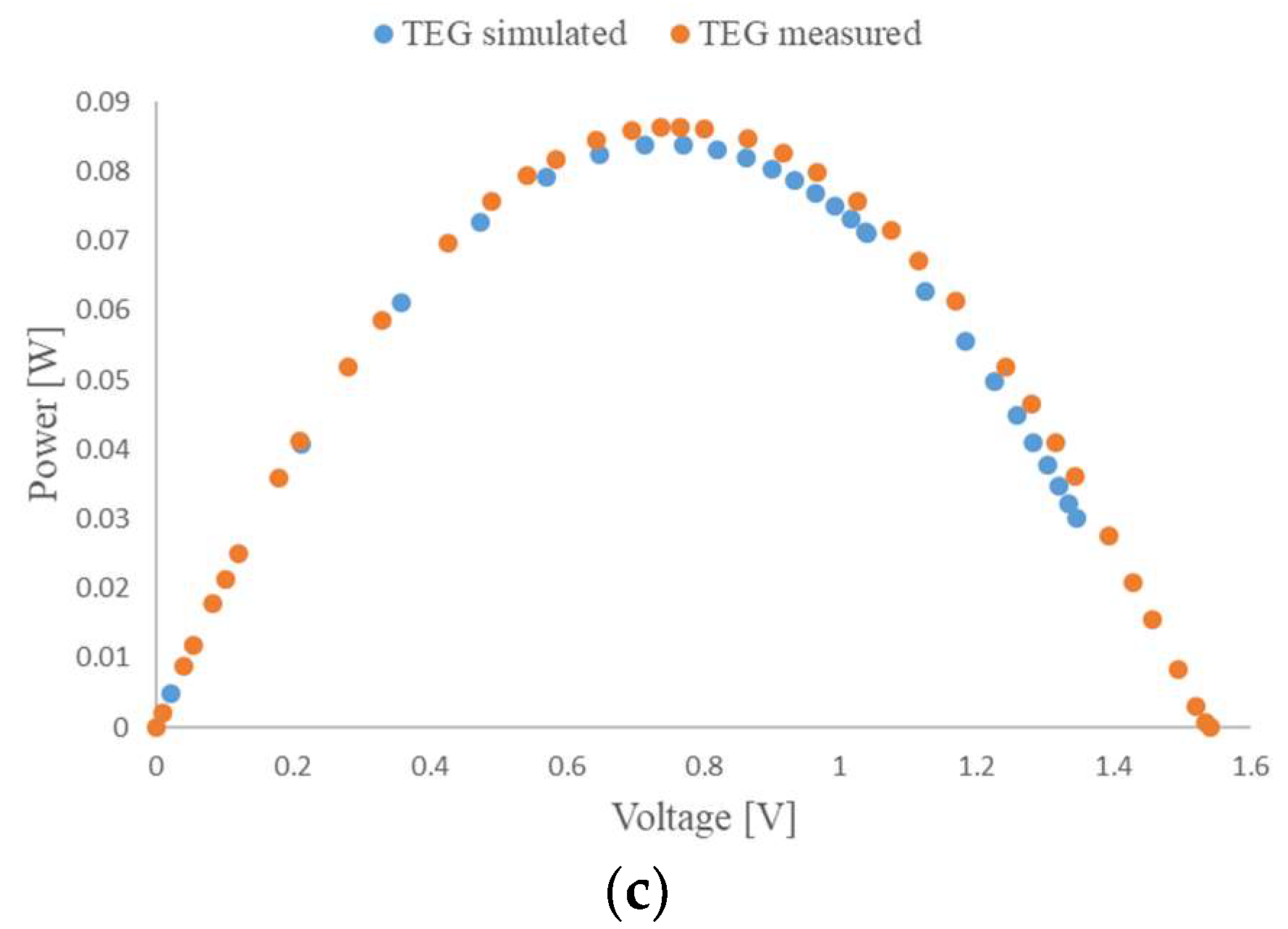
The results obtained through measurements for one commercial TEG with square-shape filled legs, with the following features: maximum voltage 16,2 V; maximum current 5.3 A; sizes 40 × 40 × 4 mm; maximum power 57 W; Bi2Te3, Al2O3, were compared with the ones obtained through simulation. The sizes of the TEG are the same, as well as the number of the NP pairs, 128, and the pitch. The P-V characteristics that were obtained through simulation and the other measured in a real case under low concentration radiation show a good matching; however, the difference decreases when the level of illumination decreases (Figure 11). The temperature of the hot side, Th, of TEG is 227 °C, 73 °C and 46 °C, and for the cold side, the temperature is 46 °C, 20 °C, and 18 °C. These temperatures are obtained for TEG when it was illuminated at different irradiance. The difference in maximum power can be due to the distribution of the temperature on the hot side of the TEG, in the real case, and perhaps a small difference between the material properties used by the manufacturer in comparison with the properties from the COMSOL Multiphysics software. The temperature was measured using two thermocouples on the hot side of the TEG, which was covered with an adhesive graphite sheet, and three thermocouples on the cold side of TEG.

4. Conclusions

Thirteen thermoelectric generators are simulated in COMSOL Multiphysics software, where 3D numerical models were developed and solved using the finite element method. The thirteen TEGs are: filled square, which is the conventional leg shape, and the commercial one, hollow square, filled and hollow triangular, filled and hollow trapezoid, filled and hollow reverse trapezoid, filled and hollow hourglass, filled and hollow inverse hourglass and internal hollow square which is studied for the first time. In the first case, the temperature of the hot side was 227 °C and for the cold side, it was 46 °C. These were used in the simulation because the performance of the commercial TEG was measured under illumination in concentrated light at 120 suns and these temperatures were obtained. The TEG with filled square legs had the best performance for the three scenarios for the length and width of 1 mm × 1 mm, 1.5 mm × 1.5 mm, and 2 mm × 2 mm. The maximum power generated by the TEG with filled square legs was the highest in the third scenario. Using the hollow legs means a reduction in the materials and implicitly in the costs. The reduction in the maximum power for the TEG with square legs, 2 mm × 2 mm, which are hollow is 5%. A possibility for improving the performance is to use TEGs with square legs which have internal hollows, for the TEG (2 mm × 2 mm) the maximum power increases by 0.2% and for TEG (1 mm × 1 mm) by 1%. When natural convection and forced convection are used for the cold side of the TEG and the hot side is kept at 227 °C, there are some changes; the most important being that the temperature difference between the hot and cold sides decreases, resulting in a decrease in the maximum power generated by the TEG and which is variable from TEG to TEG. Therefore, for natural convection, the temperature difference decreases from 181 °C to 6 °C and the behavior of the maximum power is inverse in comparison with the case when the temperature difference is constant. The highest maximum power is obtained for the TEG with triangular legs with an internal hollow (1 mm × 1 mm). This TEG has the best performance and for the forced convection with h = 20 W/(m2K). In case of the forced convection with h = 200 W/(m2K) the best performance is obtained by the TEG with the hollow, triangular legs (2 mm × 2 mm). The comparison between the power generated by the TEG with the filled square leg under illumination and the one obtained through simulation shows a good matching and the model can be used successfully. The future work will be to analyze and find a good solution for the reduction in the materials used for the legs using different shapes and hollows.

Author Contributions

A.R. achieved the simulation on Comsol; D.T.C. was responsible for the methodology and writing the manuscript; D.T.C. and P.A.C. conceived and conducted the experiments. All authors have read and agreed to the published version of the manuscript.

Funding

This research received no external funding.

Institutional Review Board Statement

Not applicable.

Informed Consent Statement

Not applicable.

Data Availability Statement

Not applicable.

Acknowledgments

Abdelkader Rjafallah and D.T Cotfas are highly grateful to the “Romanian Ministry of Foreign Affairs” and the “Agence Universitaire de la Francophonie” for the “Eugen Ionescu” mobility grant from the “Transilvania University of Brasov”, Brasov, Romania. The authors thank the IMDEA Energy Institute for providing access to its installations, the support of its scientific and technical staff, and the financial support of the SFERA-III project (Grant Agreement No 823802).

Conflicts of Interest

The authors declare no conflict of interest.

References

  1. Mahmoudinezhad, S.; Cotfas, P.A.; Cotfas, D.T.; Rosendahl, L.A.; Rezania, A. Response of thermoelectric generators to Bi2Te3 and Zn4Sb3 energy harvester materials under variant solar radiation. Renew. Energy 2020, 146, 2488–2498. [Google Scholar] [CrossRef]
  2. Mahmoudinezhad, S.; Cotfas, P.A.; Cotfas, D.T.; Skjølstrup, E.J.H.; Pedersen, K.; Rosendahl, L.A.; Rezania, A. An Experimental Study on Transient Response of a Hybrid Thermoelectric–Photovoltaic System with Beam Splitter. Energies 2021, 14, 8129. [Google Scholar] [CrossRef]
  3. Shen, Z.G.; Tian, L.L.; Liu, X. Automotive exhaust thermoelectric generators: Current status, challenges and future prospects. Energy Convers. Manag. 2019, 195, 1138–1173. [Google Scholar] [CrossRef]
  4. Ambrosi, R.M.; Williams, H.; Watkinson, E.J.; Barco, A.; Mesalam, R.; Crawford, T.; Bicknell, C.; Samara-Ratna, P.; Vernon, D.; Bannister, N.; et al. European Radioisotope Thermoelectric Generators (RTGs) and Radioisotope Heater Units (RHUs) for Space Science and Exploration. Space Sci. Rev. 2019, 215, 55. [Google Scholar] [CrossRef]
  5. Cotfas, D.T.; Cotfas, P.A.; Ciobanu, D.; Machidon, O.M. Characterization of photovoltaic–thermoelectric–solar collector hybrid systems in natural sunlight conditions. J. Energy Eng. 2017, 143, 04017055. [Google Scholar] [CrossRef]
  6. Cotfas, P.A.; Cotfas, D.T. Comprehensive review of methods and instruments for photovoltaic–thermoelectric generator hybrid system characterization. Energies 2020, 13, 6045. [Google Scholar] [CrossRef]
  7. Cui, Y.J.; Wang, K.F.; Zheng, L.; Wang, B.L.; Zhang, C.W. Theoretical model of fatigue crack growth of a thermoelectric pn-junction bonded to an elastic substrate. Mech. Mater. 2020, 151, 103623. [Google Scholar] [CrossRef]
  8. Jouhara, H.; Żabnieńska-Góra, A.; Khordehgah, N.; Doraghi, Q.; Ahmad, L.; Norman, L.; Axcell, B.; Wrobel, L.; Dai, S. Thermoelectric generator (TEG) technologies and applications. Int. J. 2021, 9, 100063. [Google Scholar] [CrossRef]
  9. Ni, D.; Song, H.; Chen, Y.; Cai, K. Free-standing highly conducting PEDOT films for flexible thermoelectric generator. Energy 2019, 170, 53–61. [Google Scholar] [CrossRef]
  10. Zhu, H.; Mao, J.; Feng, Z.; Sun, J.; Zhu, Q.; Liu, Z.; Singh, D.J.; Wang, Y.; Ren, Z. Understanding the asymmetrical thermoelectric performance for discovering promising thermoelectric materials. Sci. Adv. 2019, 5, eaav5813. [Google Scholar] [CrossRef] [Green Version]
  11. Pei, J.; Cai, B.; Zhuang, H.L.; Li, J.F. Bi2Te3-based applied thermoelectric materials: Research advances and new challenges. Natl. Sci. Rev. 2020, 7, 1856–1858. [Google Scholar] [CrossRef] [PubMed]
  12. Olivares-Robles, M.A.; Badillo-Ruiz, C.A.; Ruiz-Ortega, P.E. A comprehensive analysis on nanostructured materials in a thermoelectric micro-system based on geometric shape, segmentation structure and load resistance. Sci. Rep. 2020, 10, 21659. [Google Scholar] [CrossRef] [PubMed]
  13. Soleimani, Z.; Zoras, S.; Ceranic, B.; Shahzad, S.; Cui, Y. A review on recent developments of thermoelectric materials for room temperature applications. Sustain. Energy Technol. Assess. 2020, 37, 100604. [Google Scholar] [CrossRef]
  14. Nozariasbmarz, A.; Krasinski, J.S.; Vashaee, D. N-Type bismuth telluride nanocomposite materials optimization for thermoelectric generators in wearable applications. Materials 2019, 12, 1529. [Google Scholar] [CrossRef] [PubMed]
  15. Witting, I.T.; Chasapis, T.C.; Ricci, F.; Peters, M.; Heinz, N.A.; Hautier, G.; Snyder, G.J. The Thermoelectric Properties of Bismuth Telluride. Adv. Electron. Mater. 2019, 5, 1800904. [Google Scholar] [CrossRef]
  16. Cui, Y.J.; Wang, B.L.; Wang, K.F. Thermally induced vibration and strength failure analysis of thermoelectric generators. Appl. Therm. Eng. 2019, 160, 113991. [Google Scholar] [CrossRef]
  17. Sisik, B.; LeBlanc, S. The influence of leg shape on thermoelectric performance under constant temperature and heat flux boundary conditions. Front. Mater. 2020, 7, 595955. [Google Scholar] [CrossRef]
  18. Fabián-Mijangos, A.; Min, G.; Alvarez-Quintana, J. Enhanced performance thermoelectric module having asymmetrical legs. Energy Convers. Manag. 2017, 148, 1372–1381. [Google Scholar] [CrossRef]
  19. Jovovic, V. Thermoelectric Waste Heat Recovery Program for Passenger Vehicles. Available online: http://energy.gov/sites/prod/files/2014/07/f17/ace080_barnhart_2014_o.pdf (accessed on 22 June 2022).
  20. Schmitz, A.; Stiewe, C.; Müller, E. Preparation of ring-shaped thermoelectric legs from PbTe powders for tubular thermoelectric modules. J. Electron. Mater. 2013, 42, 1702. [Google Scholar] [CrossRef]
  21. Sahin, A.Z.; Yilbas, B.S. The Thermoelement as Thermoelectric Power Generator: Effect of Leg Geometry on the Efficiency and Power Generation. Energy Convers. Manag. 2013, 65, 26–32. [Google Scholar] [CrossRef]
  22. Fateh, H.; Baker, C.A.; Hall, M.J.; Shi, L. High fidelity finite difference model for exploring multi-parameter thermoelectric generator design space. Appl. Energy 2014, 129, 373–383. [Google Scholar] [CrossRef]
  23. Thimont, Y.; LeBlanc, S. The impact of thermoelectric leg geometries on thermal resistance and power output. J. Appl. Phys. 2019, 126, 095101. [Google Scholar] [CrossRef]
  24. Liu, H.B.; Meng, J.H.; Wang, X.D.; Chen, W.H. A new design of solar thermoelectric generator with combination of segmented materials and asymmetrical legs. Energy Convers. Manag. 2018, 175, 11–20. [Google Scholar] [CrossRef]
  25. Li, M.; Dizaji, H.S.; Asaadi, S.; Jarad, F.; Anqi, A.E.; Wae-hayee, M. Thermo-economic, exergetic and mechanical analysis of thermoelectric generator with hollow leg structure; impact of leg cross-section shape and hollow-to-filled area ratio. Case Stud. Therm. Eng. 2021, 27, 101314. [Google Scholar] [CrossRef]
  26. Mahmoudinezhad, S.; Ahmadi Atouei, S.; Cotfas, P.A.; Cotfas, D.T.; Rosendahl, L.A.; Rezania, A. Experimental and numerical study on the transient behavior of multi-junction solar cell-thermoelectric generator hybrid system. Energy Convers. Manag. 2019, 184, 448–455. [Google Scholar] [CrossRef]
  27. Liu, Z.; Zhu, S.; Ge, Y.; Shan, F.; Zeng, L.; Liu, W. Geometry optimization of two-stage thermoelectric generators using simplified conjugate-gradient method. Appl. Energy 2017, 190, 540–552. [Google Scholar] [CrossRef]
  28. Hogblom, O.; Andersson, R. Analysis of thermoelectric generator performance by use of simulations and experiments. J. Electron. Mater. 2014, 43, 2247–2254. [Google Scholar] [CrossRef]
  29. Memon, S.; Tahir, K.N. Experimental and analytical simulation analyses on the electrical performance of thermoelectric generator modules for direct and concentrated quartz-halogen heat harvesting. Energies 2018, 11, 3315. [Google Scholar] [CrossRef]
  30. Bensafi, M.; Ameur, H.; Kaid, N.; Hoseinzadeh, S.; Memon, S.; Sohani, A. Experimental Study of Electric Power Generation with Concentrated Solar Thermoelectric Generator. Electronics 2022, 11, 1867. [Google Scholar] [CrossRef]
  31. Sun, D.; Shen, L.; Yao, Y.; Chen, H.; Jin, S.; He, H. The real-time study of solar thermoelectric generator. Appl. Therm. Eng. 2017, 119, 347–359. [Google Scholar] [CrossRef]
  32. Available online: https://www.comsol.com (accessed on 12 February 2022).
  33. Prasad, A.; Thiagarajan, R.C.N. Multiphysics Modelling and Multilevel Optimization of Thermoelectric Generator for Waste Heat Recovery, ATOA Scientific Technologies, Bengaluru. Available online: cn.comsol.com (accessed on 21 June 2022).
  34. Cui, Y.J.; Wang, K.F.; Wang, B.L.; Li, J.E.; Zhou, J.Y. A comprehensive analysis of delamination and thermoelectric performance of thermoelectric pn-junctions with temperature-dependent material properties. Compos. Struct. 2019, 229, 111484. [Google Scholar] [CrossRef]
  35. Shittu, S.; Li, G.; Zhao, X.; Ma, X.; Akhlaghi, Y.G.; Ayodele, E. Optimized high performance thermoelectric generator with combined segmented and asymmetrical legs under pulsed heat input power. J. Power Sources 2019, 428, 53–66. [Google Scholar] [CrossRef]
  36. Jaziri, N.; Boughamoura, A.; Müller, J.; Mezghani, B.; Tounsi, F.; Ismail, M. A comprehensive review of Thermoelectric Generators: Technologies and common applications. Energy Rep. 2020, 6, 264–287. [Google Scholar] [CrossRef]
  37. Cui, Y.J.; Wang, B.L.; Wang, K.F.; Zheng, L. Power output evaluation of a porous annular thermoelectric generator for waste heat harvesting. Int. J. Heat Mass Transf. 2019, 137, 979–989. [Google Scholar] [CrossRef]
  38. Available online: https://energia.imdea.org/en/instalaciones/ (accessed on 21 June 2022).
  39. Available online: https://www.comsol.com/material-library (accessed on 21 June 2022).
  40. Available online: https://www.Tecteg.com (accessed on 21 June 2022).
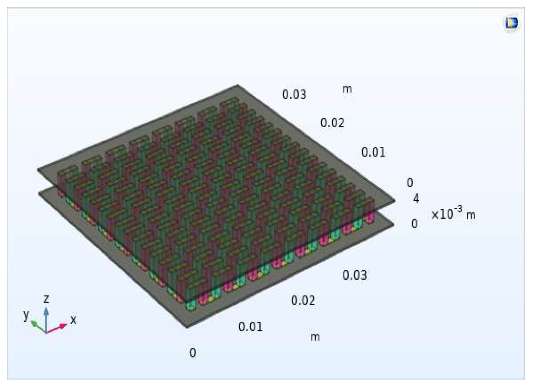
Figure 1. Thermoelectric module simulated in COMSOL Multiphysics software composed of 2 alumina ceramics, 257 copper conductors, and 128 pairs NP, square shaped legs of 1 mm × 1 mm × 3.2 mm dimensions.
Sustainability 14 15823 g001
Figure 2. Thermoelectric leg shapes investigated in this study were: (A) Filled Square (the conventional leg shape); (B) Filled Triangular; (C) Filled Trapezoid; (D) Filled Reverse Trapezoid; (E) Filled Hourglass; (F) Filled Inverse Hourglass; (A’) Hollow Square; (B’) Hollow Triangular; (C’) Hollow Trapezoid; (D’) Hollow Reverse Trapezoid; (E’) Hollow Hourglass; (F’) Hollow Inverse Hourglass.
Sustainability 14 15823 g002
Figure 3. Results reproduced using our model for one NP pair under steady-state heating condition: (a) simulated one NP pair in COMSOL Multiphysics; (b) I-V power characteristic; and (c) P-V power characteristic.
Sustainability 14 15823 g003
Figure 4. I-V and P-V power characteristics of the TEGs which have filled legs under steady-state heating condition: (a) first scenario; (b) second scenario; and (c) third scenario.
Sustainability 14 15823 g004aSustainability 14 15823 g004b
Figure 5. I-V and P-V characteristics of the TEGs which have hollow legs of the TEG under steady-state heating condition: (a) first scenario; (b) second scenario; and (c) third scenario.
Sustainability 14 15823 g005aSustainability 14 15823 g005b
Figure 6. Comparison between the maximum power generated by TEG with square-shape legs, filled and hollow.
Sustainability 14 15823 g006
Figure 7. P-V characteristics of the TEGs which have filled legs and hollow legs under constant hot side temperature (Th) and cold side h = 10 W/(m2K) natural convection (Tc) boundary conditions: (a) first scenario; (b) second scenario; and (c) third scenario.
Sustainability 14 15823 g007
Figure 8. P-V characteristics of the TEGs which have filled legs and hollow legs under constant hot side temperature (Th) and cold side h = 20 W/(m2K) forced convection (Tc) boundary conditions: (a) first scenario; (b) second scenario; and (c) third scenario.
Sustainability 14 15823 g008aSustainability 14 15823 g008b
Figure 9. P-V characteristics of the TEGs which have filled legs and hollow legs under constant hot side temperature (Th) and cold side h = 200 W/(m2K) forced convection (Tc) boundary conditions: (a) first scenario; (b) second scenario; and (c) third scenario.
Sustainability 14 15823 g009aSustainability 14 15823 g009b
Figure 10. (a) Thermoelectric square leg with an internal hollow and P-V characteristics of the TEGs which have legs with an internal hollow and are hollow of the TEG under steady-state heating condition: (b) first scenario; (c) second scenario; and (d) third scenario.
Sustainability 14 15823 g010
Figure 11. P-V characteristics of the TEG: (a) Th = 227 °C; Th = 46 °C (b) Th = 73 °C; Th = 20 °C and (c) Th = 46 °C; Th = 18 °C.
Sustainability 14 15823 g011aSustainability 14 15823 g011b
Table 1. Comparison of the model implemented with one from specialized literature.
SimulationTh = 100 °C, Tc = 30 °CTh = 200 °C, Tc = 30 °CTh = 300 °C, Tc = 30 °C
Pmax (mW)Isc (A)Voc (V)Pmax (mW)Isc (A)Voc (V)Pmax (mW)Isc (A)Voc (V)
[28]8.30.930.0339.81.90.079952.970.12
This paper7.50.890.0338.21.860.075932.90.12
Table 2. Geometric dimensions of TEGs used in simulation.
NameDimensions (mm)Description
TEG length40Total TEG length
TEG width40Total TEG width
TEG height4Total TEG height
Ceramic length 40Ceramic length
Ceramic width40Ceramic width
Ceramic height0.3Ceramic thickness
Copper height0.1Copper thickness
Leg height3.2Leg height
Leg length11.52Leg length
Leg width 11.52Leg width
Pitch 1.30.90.4Distance between legs
NP128Number of thermocouples
Table 3. Material properties used in simulation.
MaterialsThermal
Conductivity
κ
(W/(m × K))
Electrical
Conductivity
σ
(S/m)
Specific
Heat Capacity
Cp
(J/(kg × K))
Density
ρ
(kg/m3)
Thermal
Expansion Coefficient
(1/K)
Young’s
Modulus
E
(GPa)
Poisson’s
Ratio
ν
Seebeck
Coefficient
S
(V/K)
Ceramic 271 × 10−1290039008 × 10−63000.220
Copper 4005.998 × 10738589401.7 × 10−51260.346.5 × 10−6
Bi2Te3
- p-type
- n-type
1.6
1.6
1.25 × 10⁵
1.25 × 10⁵
154
154
6800
6800
---
---
65–59
65–59
0.23
0.23
−210 × 10−6
210 × 10−6
Table 4. The short circuit current, open circuit voltage, and maximum power for filled legs.
FilledSquareTriangularTrapezoidReverse TrapezoidHourglassInverse Hourglass
Leg Dimension1 (mm) × 1 (mm) × 3.2 (mm)
Short circuit current (A)1.42480.72580.72340.72340.71820.7163
Open circuit voltage (V)9.67399.69669.69729.6979.70189.6941
Power Output (W)3.49401.77261.76681.76711.75481.7486
Leg Dimension1.5 (mm) × 1.5 (mm) × 3.2 (mm)
Short circuit current (A)3.11971.60811.59661.59661.57341.5648
Open circuit voltage (V)9.65929.68549.68629.6879.69439.6809
Power Output (W)7.78273.95853.93023.93113.87603.8492
Leg Dimension2 (mm) × 2 (mm) × 3.2 (mm)
Short circuit current (A)5.37282.80772.77332.77342.71122.6876
Open circuit voltage (V)9.64499.67519.67629.67699.68749.6695
Power Output (W)13.5636.98406.89236.89476.73356.6580
Table 5. The short circuit current, open circuit voltage, and maximum power for hollow legs.
HollowSquareTriangularTrapezoidReverse TrapezoidHourglassInverse Hourglass
Leg Dimension1 (mm) × 1 (mm) × 3.2 (mm)
Short circuit current (A)1.07980.54750.61780.61780.61350.6121
Open circuit voltage (V)9.68849.70579.70279.70329.70619.7002
Power Output (W)2.64431.32991.50781.50801.49791.4934
Leg Dimension1.5 (mm) × 1.5 (mm) × 3.2 (mm)
Short circuit current (A)2.79461.21811.49641.49651.47401.4668
Open circuit voltage (V)9.66769.69789.68969.69039.69699.6848
Power Output (W)6.94412.98993.67963.68043.62503.6022
Leg Dimension2 (mm) × 2 (mm) × 3.2 (mm)
Short circuit current (A)5.06872.13662.67862.67862.61342.5971
Open circuit voltage (V)9.65059.69049.67869.67939.68929.6725
Power Output (W)12.8335.28436.63866.64076.47936.4287
Table 6. The short circuit current and maximum power for TEGs which have filled legs: Hot Side Th = 227 °C−Cold Side Tc (Natural Convection: h = 10 W/(m2K)).
FilledSquareTriangularTrapezoidReverse TrapezoidHourglassInverse Hourglass
Leg Dimension1 (mm) × 1 (mm) × 3.2 (mm)
Temp. Range (°C)
(Difference (°C))
204–227
(23)
190–227
(37)
190–227
(37)
190–227
(37)
190–227
(37)
190–227
(37)
Short circuit current (A)73.97 × 10−371.53 × 10−371.52 × 10−371.52 × 10−371.49 × 10−371.46 × 10⁻³
Power Output (W)23.13 × 10−340.53 × 10−340.64 × 10−340.64 × 10−340.91 × 10−340.90 × 10⁻³
Leg Dimension1.5 (mm) × 1.5 (mm) × 3.2 (mm)
Temp. Range (°C)
(Difference (°C))
216–227
(11)
207–227
(20)
207–227
(20)
207–227
(20)
207–227
(20)
207–227
(20)
Short circuit current (A)75.03 × 10−374.41 × 10−374.40 × 10−374.40 × 10−374.39 × 10−374.34 × 10⁻³
Power Output (W)11.15 × 10−320.99 × 10−321.14 × 10−321.14 × 10−321.48 × 10−321.48 × 10⁻³
Leg Dimension2 (mm) × 2 (mm) × 3.2 (mm)
Temp. Range (°C)
(Difference (°C))
220–227
(07)
215–227
(12)
215–227
(12)
215–227
(12)
214–227
(13)
214–227
(13)
Short circuit current (A)74.81 × 10−375.13 × 10−375.14 × 10−375.14E × 10−375.16 × 10−375.09 × 10⁻³
Power Output (W)6.444 × 10−312.47 × 10−312.63 × 10−312.63 × 10−312.97 × 10−312.98 × 10⁻³
Table 7. The short circuit current and maximum power for TEGs which have hollow legs: Hot Side Th = 227 °C−Cold Side Tc (Natural Convection: h = 10 W/(m2K)).
HollowSquareTriangularTrapezoidReverse TrapezoidHourglassInverse Hourglass
Leg Dimension1 (mm) × 1 (mm) × 3.2 (mm)
Temp. Range (°C)
(Difference (°C))
199–227
(28)
183–227
(44)
186–227
(41)
186–227
(41)
186–227
(41)
186–227
(41)
Short circuit current (A)73.21 × 10−369.87 × 10−370.64 × 10−370.64 × 10−370.61 × 10−370.58 × 10⁻³
Power Output (W)29.51 × 10−349.69 × 10−345.68 × 10−345.68 × 10−345.95 × 10−345.93 × 10⁻³
Leg Dimension1.5 (mm) × 1.5 (mm) × 3.2 (mm)
Temp. Range (°C)
(Difference (°C))
214–227
(13)
203–227
(24)
206–227
(21)
206–227
(21)
206–227
(21)
206–227
(21)
Short circuit current (A)75.03 × 10−373.75 × 10−374.27 × 10−374.27 × 10−374.26 × 10−374.21 × 10⁻³
Power Output (W)12.45 × 10−326.87 × 10−322.42 × 10−322.42 × 10−322.77 × 10−322.76 × 10⁻³
Leg Dimension2 (mm) × 2 (mm) × 3.2 (mm)
Temp. Range (°C)
(Difference (°C))
220–227
(07)
211–227
(16)
214–227
(13)
214–227
(13)
221–227
(06)
214–227
(13)
Short circuit current (A)74.91 × 10−374.95 × 10−375.13 × 10−375.13 × 10−375.15 × 10−375.08 × 10⁻³
Power Output (W)6.861 × 10−316.26 × 10−313.08 × 10−313.08 × 10−313.44 × 10−313.43 × 10⁻³
Table 8. The short circuit current and maximum power for TEGs which have filled legs: Hot Side Th = 227 °C−Cold Side Tc (Forced Convection: h = 20 W/(m2K)).
FilledSquareTriangularTrapezoidReverse TrapezoidHourglassInverse Hourglass
Leg Dimension1 (mm) × 1 (mm) × 3.2 (mm)
Temp. Range (°C)
(Difference (°C))
185–227
(42)
164–227
(63)
164–227
(63)
164–227
(63)
163–227
(64)
163–227
(64)
Short circuit current (A)142.0 × 10−3132.6 × 10−3132.5 × 10−3132.5 × 10−3132.4 × 10−3132.3 × 10−3
Power Output (W)80.59 × 10−3126.2 × 10−3126.5 × 10−3126.5 × 10−3127.2 × 10−3127.1 × 10−3
Leg Dimension1.5 (mm) × 1.5 (mm) × 3.2 (mm)
Temp. Range (°C)
(Difference (°C))
205–227
(22)
191–227
(36)
191–227
(36)
191–227
(36)
190–227
(37)
190–227
(37)
Short circuit current (A)147.3 × 10−3143.6 × 10−3143.6 × 10−3143.5v143.5 × 10−3143.3 × 10−3
Power Output (W)41.79 × 10−374.27 × 10−374.74 × 10−374.73 × 10−375.80 × 10−375.77 × 10⁻³
Leg Dimension2 (mm) × 2 (mm) × 3.2 (mm)
Temp. Range (°C)
(Difference (°C))
214–227
(13)
204–227
(23)
204–227
(23)
204–227
(23)
203–227
(24)
203–227
(24)
Short circuit current (A)148.0 × 10−3147.2 × 10−3147.2 × 10−3147.2 × 10−3147.1 × 10−3147.0 × 10−3
Power Output (W)24.84 × 10−346.43 × 10−346.99 × 10−346.98 × 10−348.12 × 10−348.15 × 10⁻³
Table 9. The short circuit current and maximum power for TEGs which have hollow legs: Hot Side Th = 227 °C−Cold Side Tc (Forced Convection: h = 20 W/(m2K)).
HollowSquareTriangularTrapezoidReverse TrapezoidHourglassInverse Hourglass
Leg Dimension1 (mm) × 1 (mm) × 3.2 (mm)
Temp. Range (°C)
(Difference (°C))
177–227
(50)
153–227
(74)
158–227
(69)
158–227
(69)
158–227
(69)
158–227
(69)
Short circuit current (A)138.9 × 10−3126.7 × 10−3129.4 × 10−3129.4 × 10 3129.3 × 10−3129.2 × 10−3
Power Output (W)98.85 × 10−3145.5 × 10−3137.5 × 10−3137.5 × 10−3138.1 × 10−3138.0 × 10−3
Leg Dimension1.5 (mm) × 1.5 (mm) × 3.2 (mm)
Temp. Range (°C)
(Difference (°C))
203–227
(24)
183–227
(44)
189–227
(38)
189–227
(38)
189–227
(38)
189–227
(38)
Short circuit current (A)147.0 × 10−3140.8 × 10−3143.0 × 10−3143.0 × 10−3142.9 × 10−3142.7 × 10−3
Power Output (W)46.35 × 10−391.46 × 10−378.67 × 10−378.66 × 10−379.77 × 10−379.74 × 10⁻³
Leg Dimension2 (mm) × 2 (mm) × 3.2 (mm)
Temp. Range (°C)
(Difference (°C))
213–227
(14)
198–227
(29)
203–227
(24)
203–227
(24)
215–227
(12)
202–227
(25)
Short circuit current (A)148.1 × 10−3145.9 × 10−3147.0 × 10−3147.0 × 10−3147.0 × 10−3146.8 × 10−3
Power Output (W)26.34 × 10−359.20 × 10−348.48 × 10−348.48 × 10−349.77 × 10−349.72 × 10⁻³
Table 10. The short circuit current and maximum power for TEGs which have filled legs: Hot Side Th = 227 °C−Cold Side Tc (Forced Convection: h = 200 W/(m2K)).
FilledSquareTriangularTrapezoidReverse TrapezoidHourglassInverse Hourglass
Leg Dimension1 (mm) × 1 (mm) × 3.2 (mm)
Temp. Range (°C)
(Difference (°C))
69.8–227
(157.2)
51.1–227
(175.9)
51.2–227
(175.8)
51.2–227
(175.8)
51.1–227
(175.9)
51–227
(176)
Short circuit current (A)0.80980.55290.55180.55170.54920.5482
Power Output (W)1.66021.30971.30771.30761.30351.2999
Leg Dimension1.5 (mm) × 1.5 (mm) × 3.2 (mm)
Temp. Range (°C)
(Difference (°C))
111–227
(116)
81.3–227
(145.7)
81.5–227
(145.5)
81.5–227
(145.5)
80.9–227
(146.1)
80.8–227
(146.2)
Short circuit current (A)1.09750.86550.86300.86270.85740.8548
Power Output (W)1.68381.72851.72801.72731.72591.7191
Leg Dimension2 (mm) × 2 (mm) × 3.2 (mm)
Temp. Range (°C)
(Difference (°C))
140–227
(87)
107–227
(120)
107–227
(120)
107–227
(120)
106–227
(121)
106–227
(121)
Short circuit current (A)1.23731.06731.06391.06341.05671.0529
Power Output (W)1.39381.72761.73331.73241.74431.7377
Table 11. The short circuit current and maximum power for TEGs which have hollow legs: Hot Side Th = 227 °C−Cold Side Tc (Forced Convection: h = 200 W/(m2K)).
HollowSquareTriangularTrapezoidReverse TrapezoidHourglassInverse Hourglass
Leg Dimension1 (mm) × 1 (mm) × 3.2 (mm)
Temp. Range (°C)
(Difference (°C))
61.3–227
(165.7)
45.5–227
(181.5)
47.9–227
(179.1)
47.9–227
(179.1)
47.8–227
(179.2)
47.7–227
(179.3)
Short circuit current (A)0.70270.45570.49620.49610.49390.4930
Power Output (W)1.54821.12321.20431.20421.20051.1978
Leg Dimension1.5 (mm) × 1.5 (mm) × 3.2 (mm)
Temp. Range (°C)
(Difference (°C))
106–227
(121)
71.1–227
(155.9)
79–227
(148)
79–227
(148)
78.4–227
(148.6)
78.3–227
(148.7)
Short circuit current (A)1.06360.75660.83780.83750.83200.8296
Power Output (W)1.71951.63151.71001.70941.70741.7010
Leg Dimension2 (mm) × 2 (mm) × 3.2 (mm)
Temp. Range (°C)
(Difference (°C))
137–227
(90)
94.4–227
(132.6)
106–227
(121)
106–227
(121)
144–227
(83)
104–227
(123)
Short circuit current (A)1.22570.97411.05251.05211.04461.0416
Power Output (W)1.43191.77311.74381.74291.75371.7467
Table 12. Comparison for short circuit current, open circuit voltage, and maximum power for three TEGs with square legs filled, are hollow and with an internal hollow.
TEGSquareHollow Square Square with Internal Hollow
Leg Dimension1 (mm) × 1 (mm) × 3.2 (mm)
Short circuit current (A)1.42481.07981.0864
Open circuit voltage (V)9.67399.68849.6913
Power Output (W)3.49402.64432.6704
Leg Dimension1.5 (mm) × 1.5 (mm) × 3.2 (mm)
Short circuit current (A)3.11972.79462.8028
Open circuit voltage (V)9.65929.66769.6675
Power Output (W)7.78276.94416.9658
Leg Dimension2 (mm) × 2 (mm) × 3.2 (mm)
Short circuit current (A)5.37285.06875.0771
Open circuit voltage (V)9.64499.65059.6504
Power Output (W)13.56312.83312.853
Publisher’s Note: MDPI stays neutral with regard to jurisdictional claims in published maps and institutional affiliations.