
Design and Optimization for a New Locomotive Power Battery Box


Abstract
1. Introduction
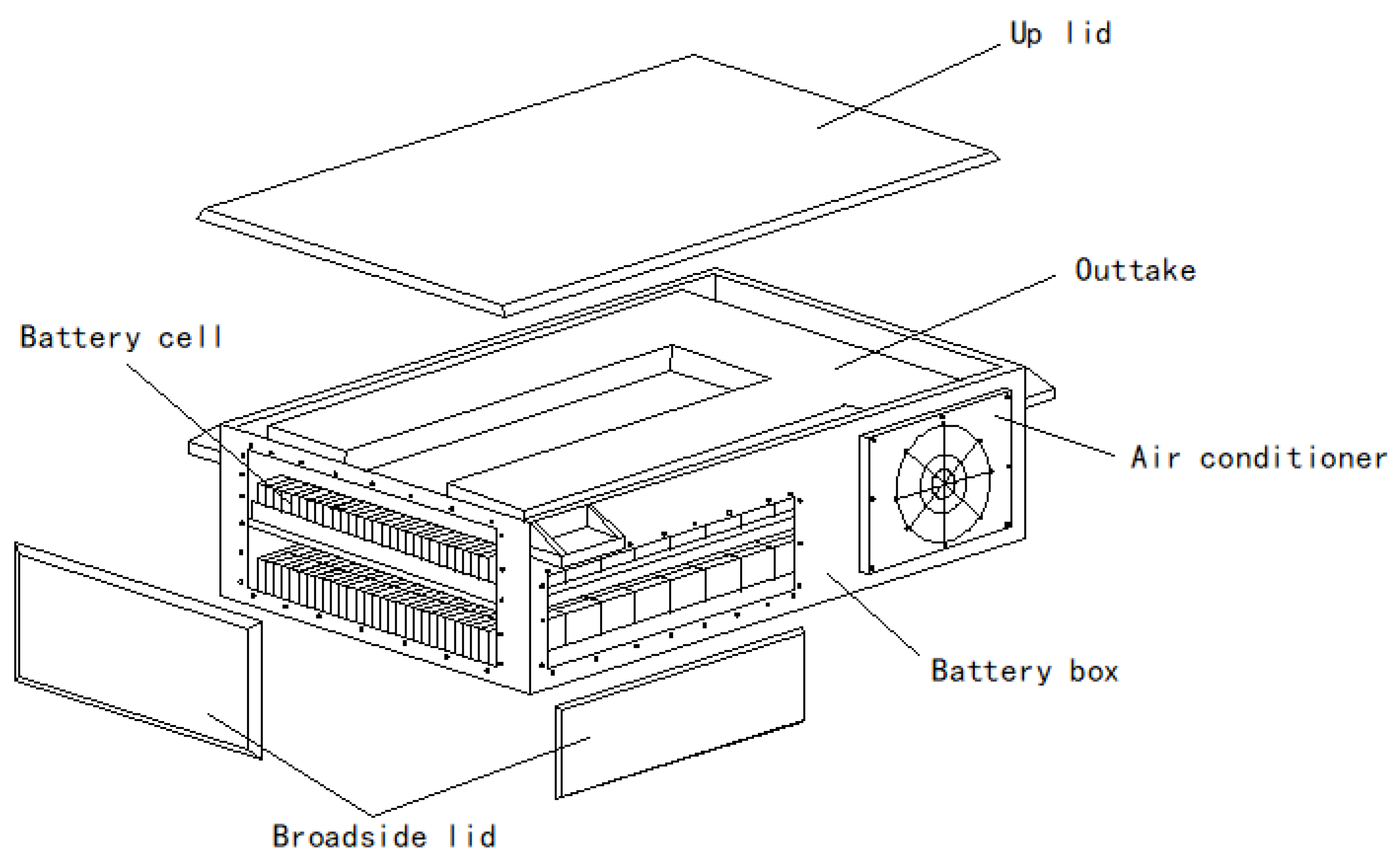
2. The Original Scheme
3. Power Battery Box Optimization
3.1. Optimization Logic
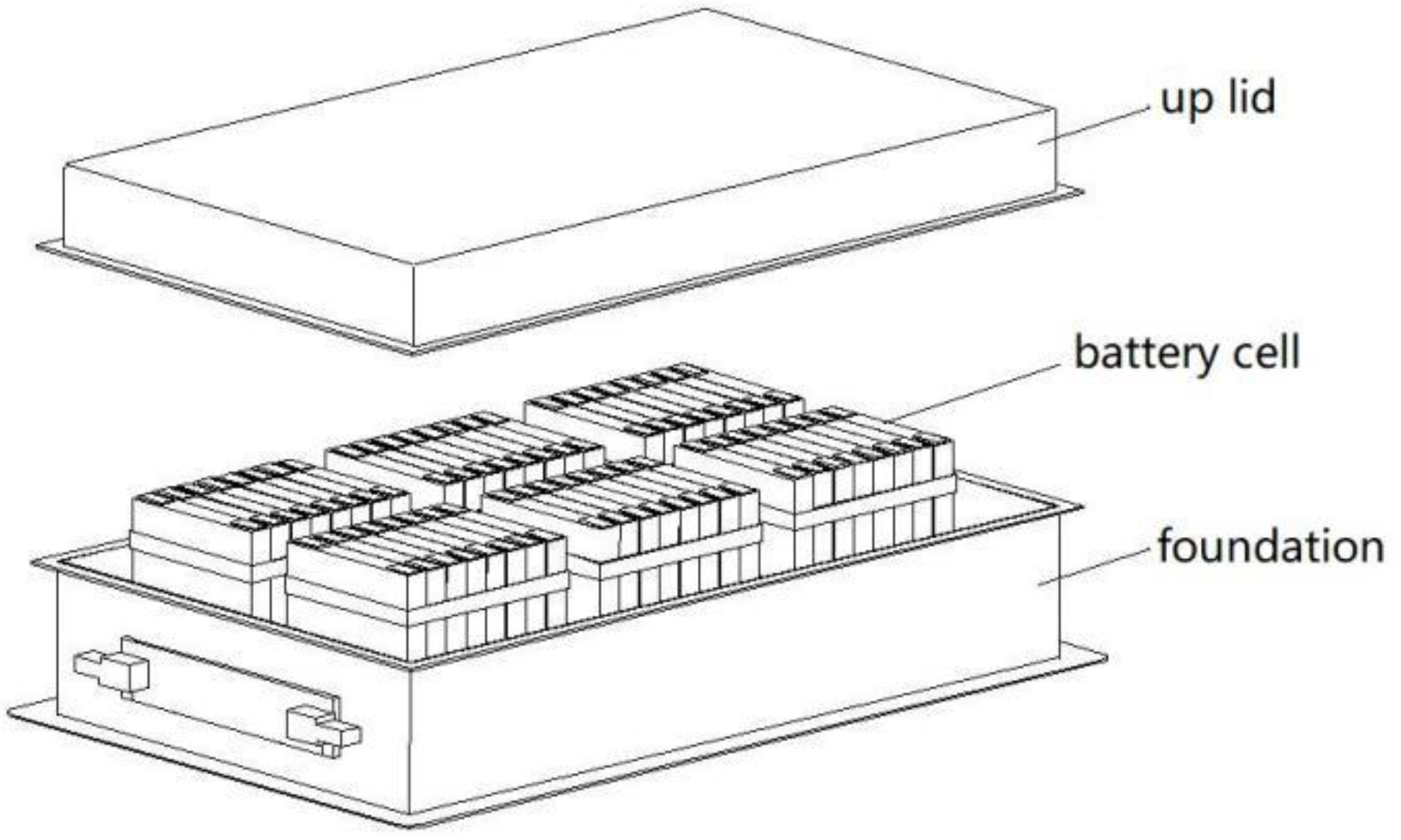
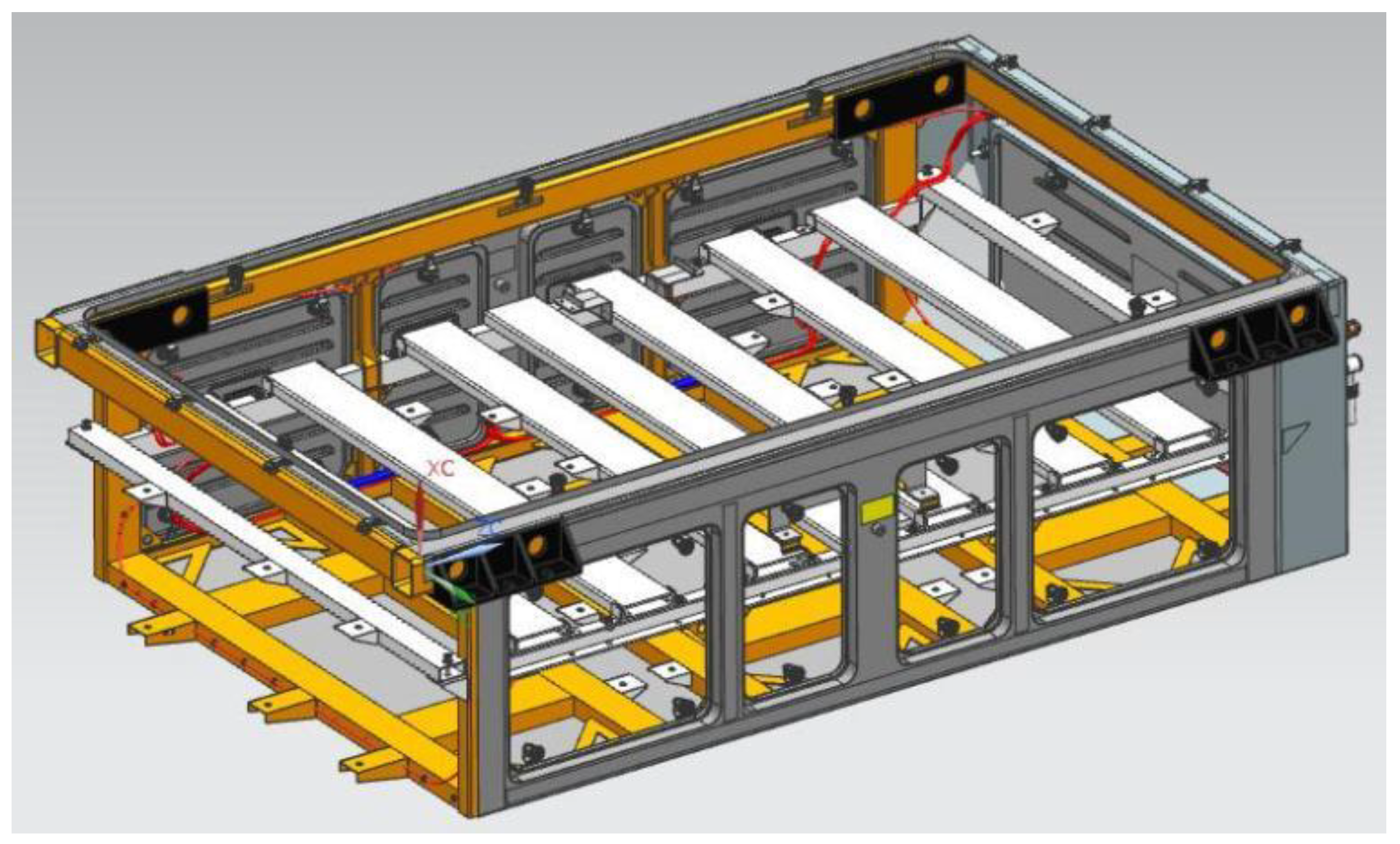
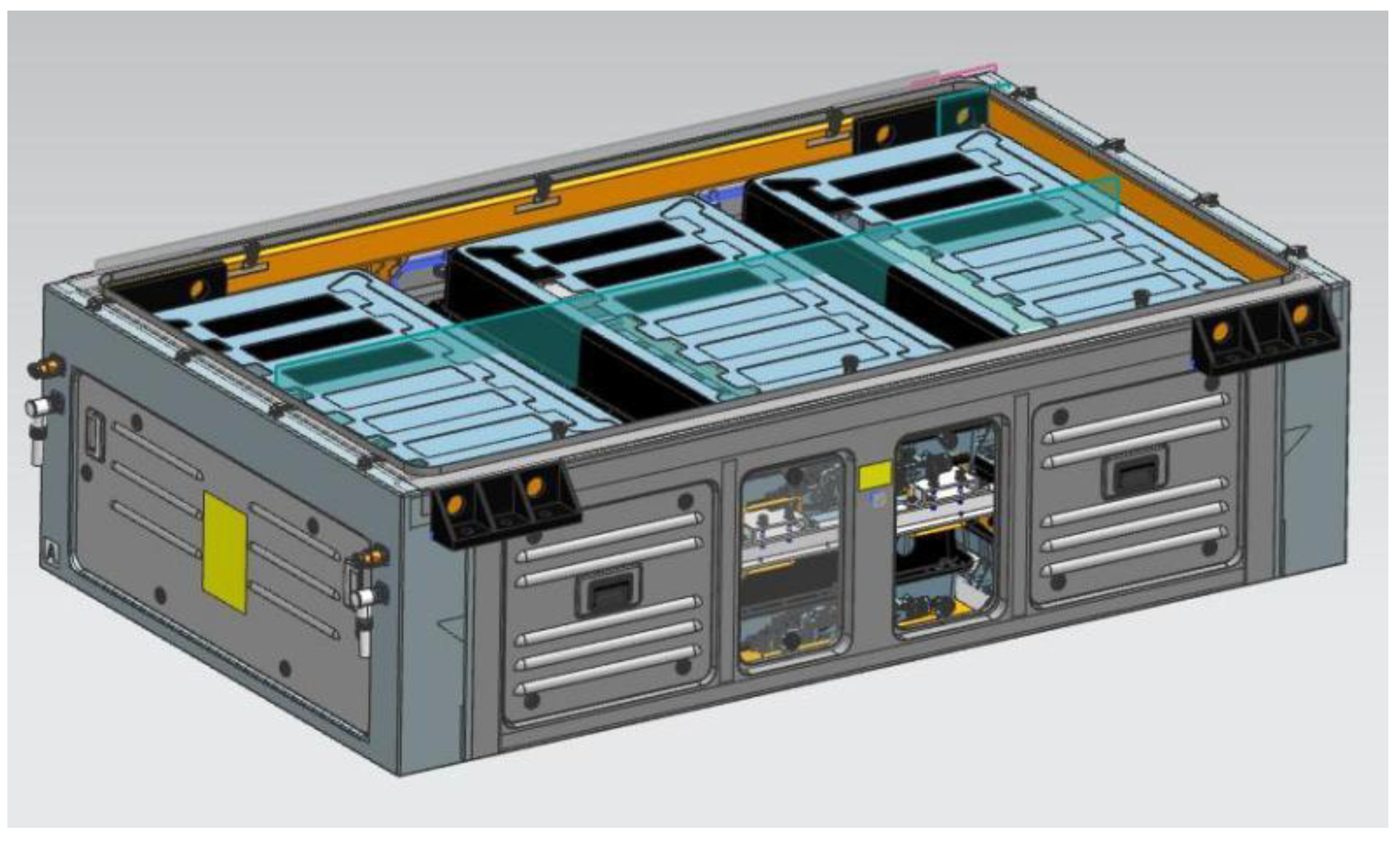
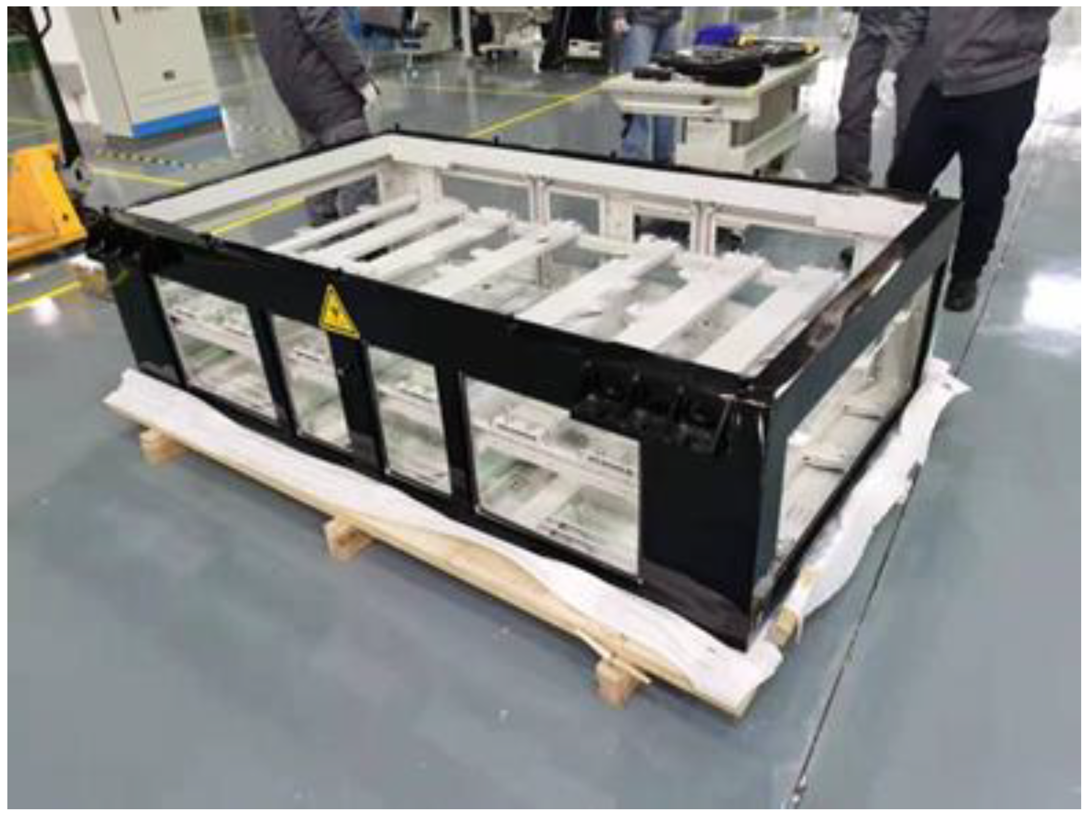
3.2. Design of Two-stage Protective Structure of Power Battery Box
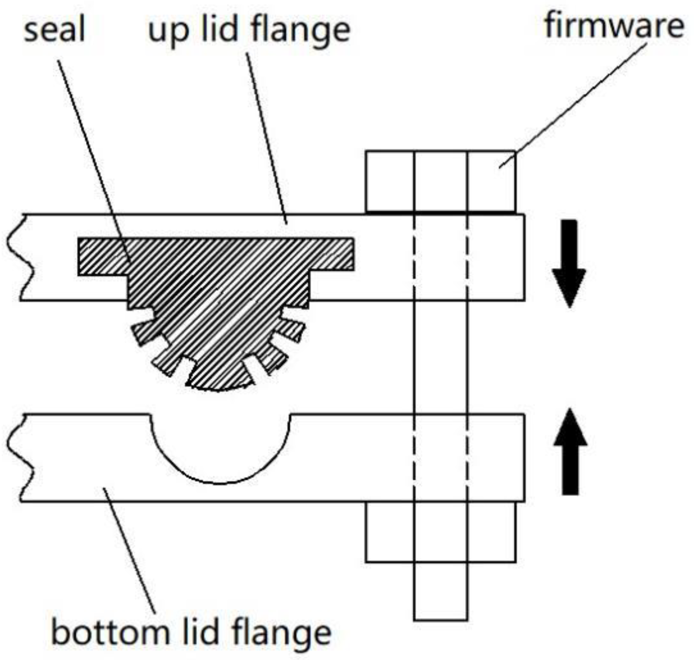
3.2.1. The First Protection Structure
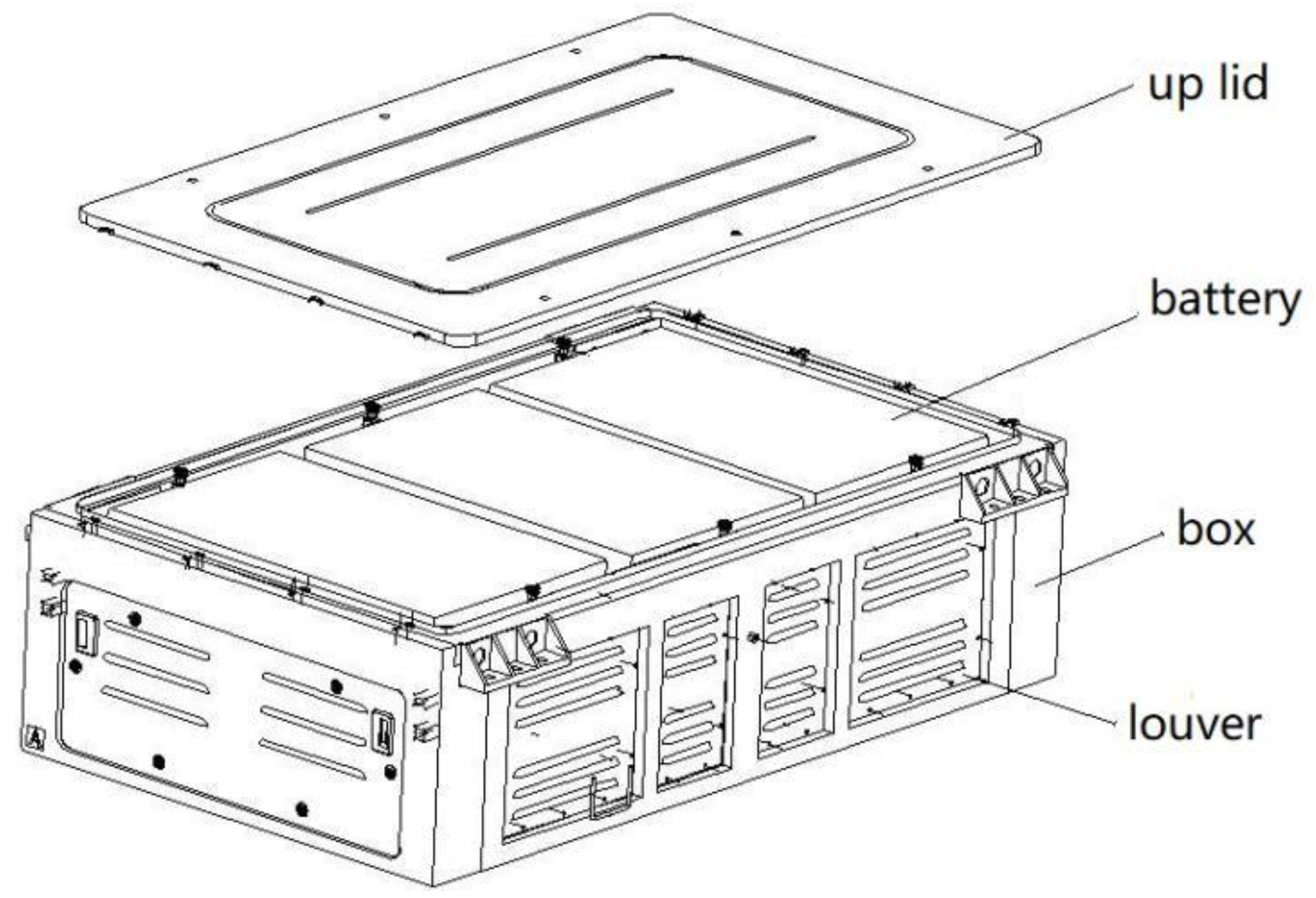
3.2.2. The Second Protective Structure
4. Simulation Analysis and Test Verification
4.1. Simulation Analysis of Power Battery Box
4.1.1. Working Conditions
4.1.2. Simulation Conditions
- (1)
- Battery self-load
- (2)
- Longitudinal impact load
- (3)
- Horizontal impact load
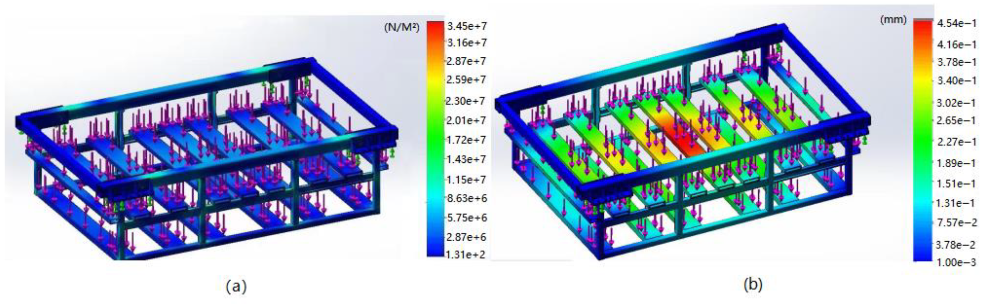
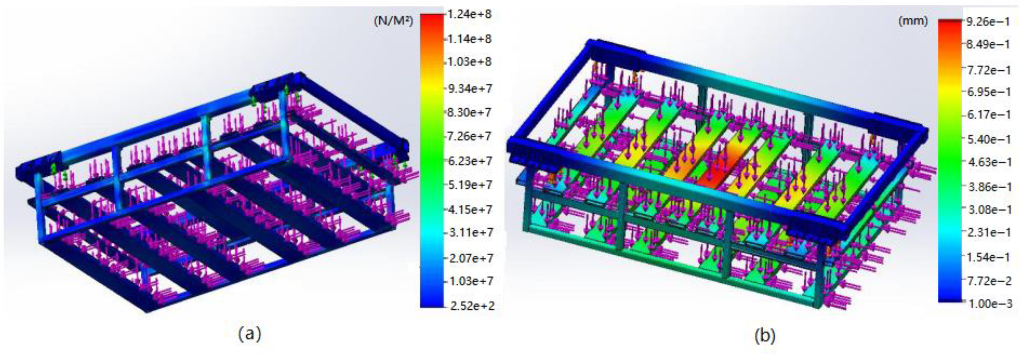
4.2. Simulation Results of Mechanical Characteristics
- (1)
- Battery self-load
- (2)
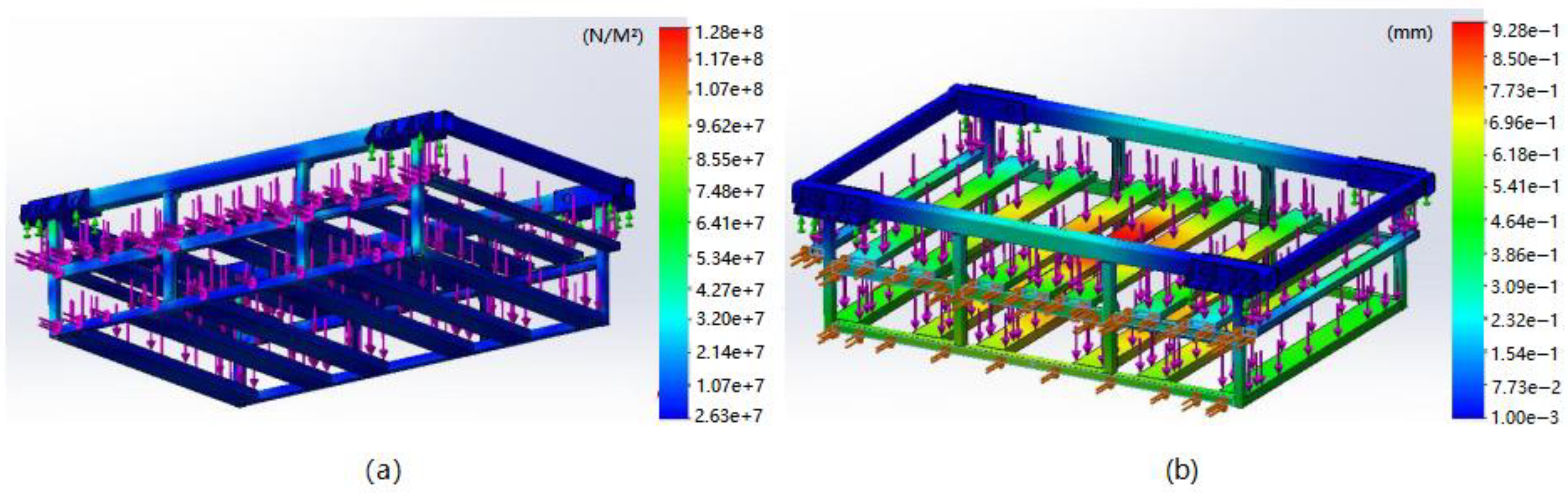
- Longitudinal impact load
- (3)
- Horizontal impact load
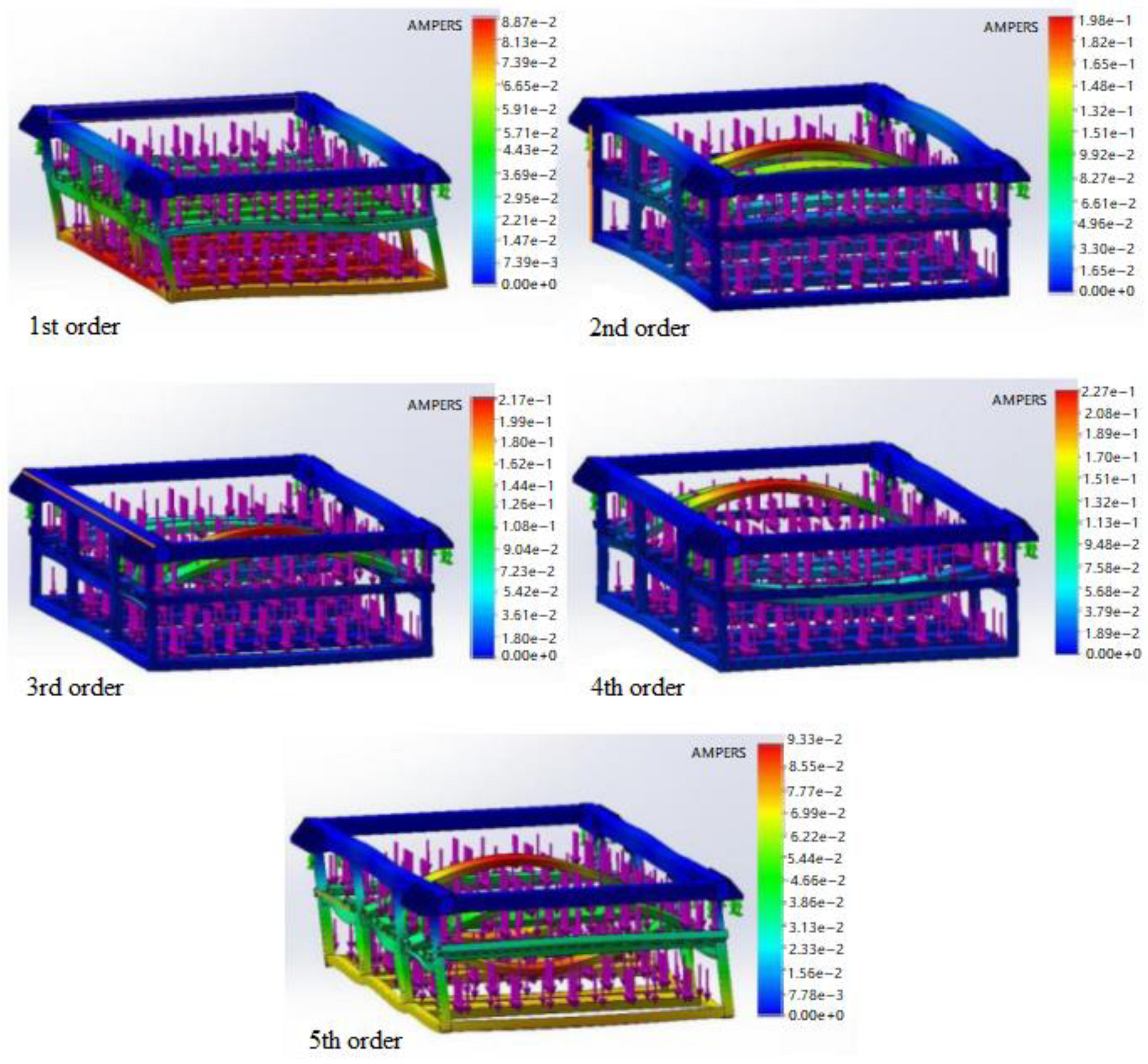
- (4)
- Modality
- (5)
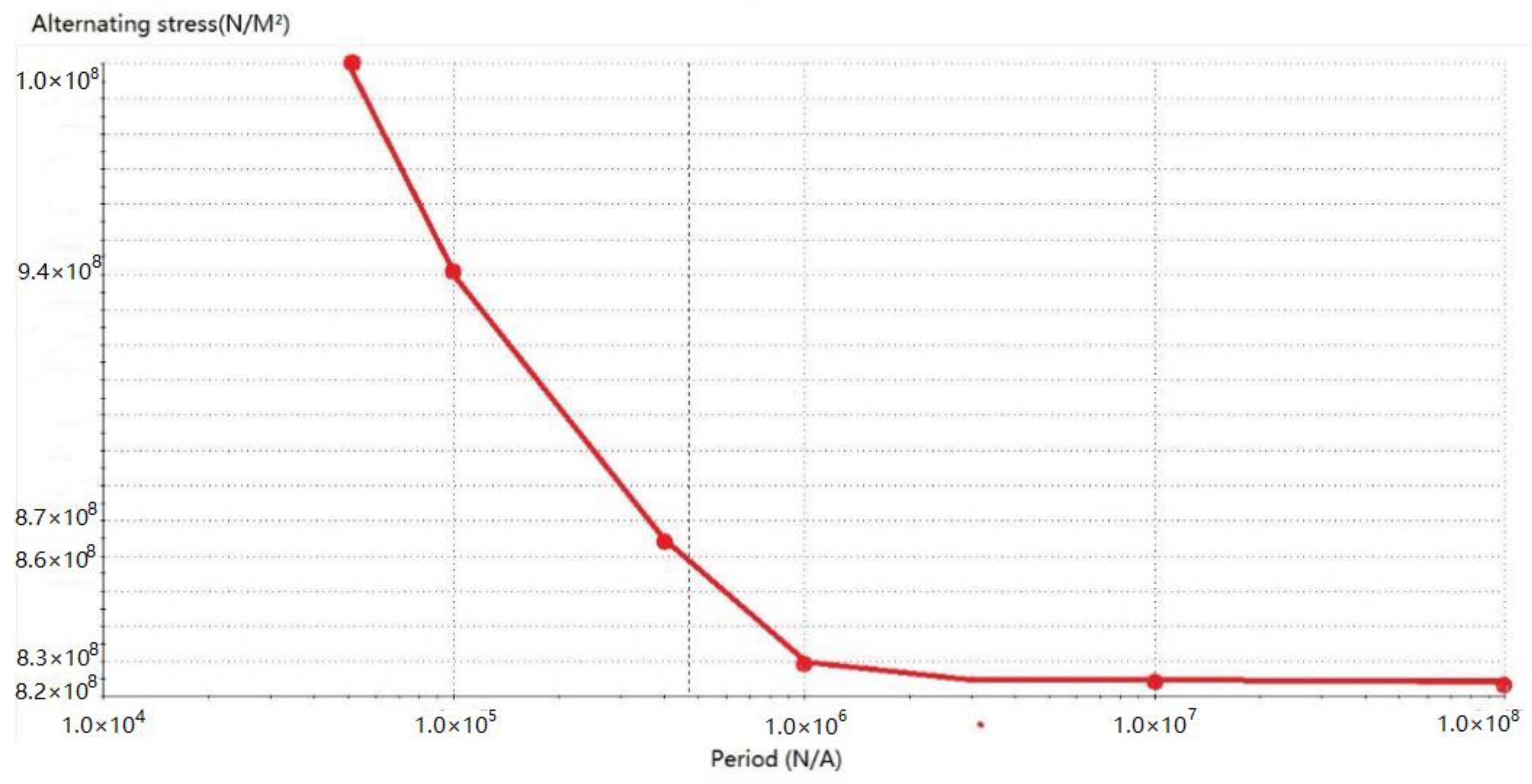
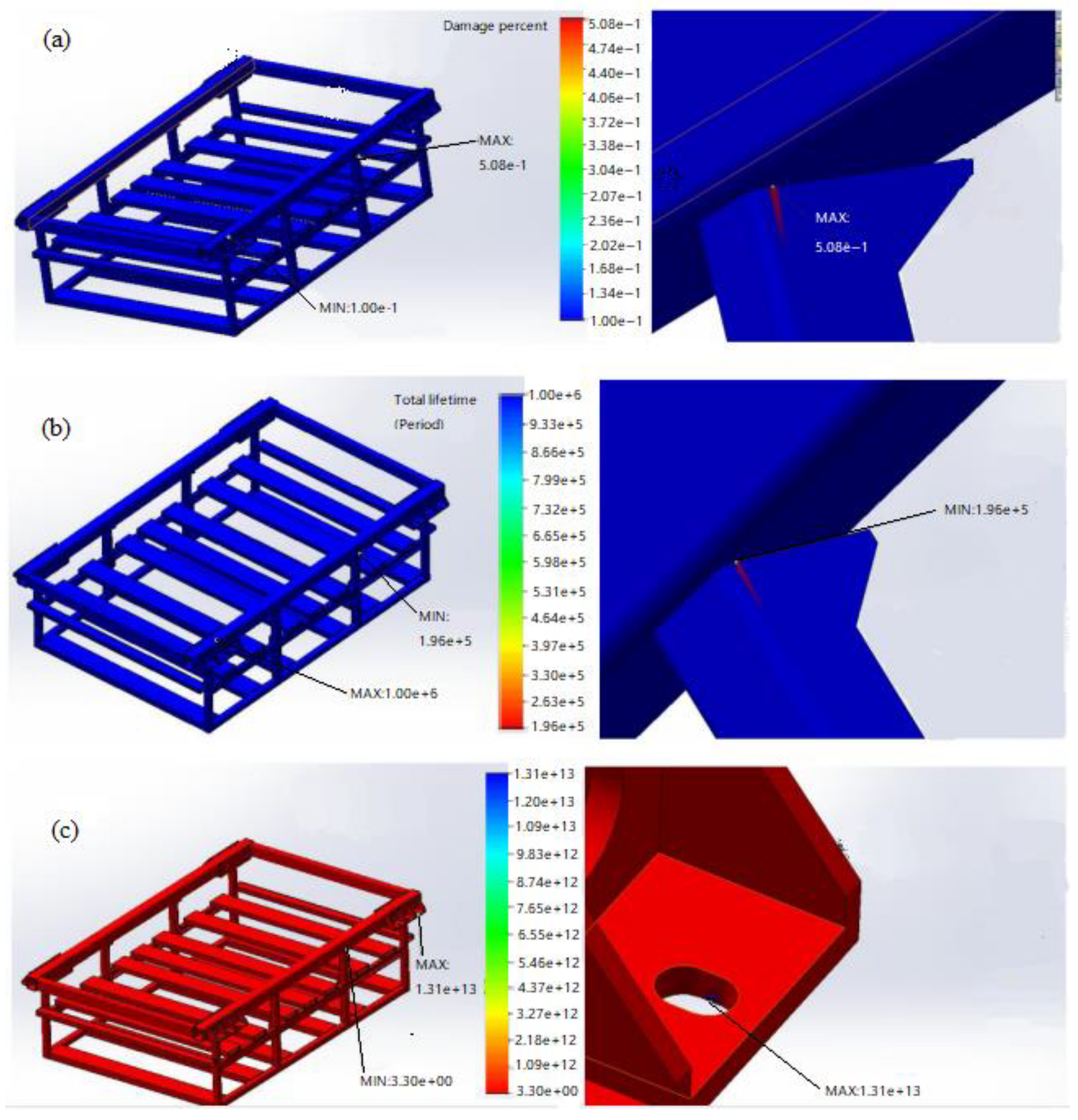
- Analysis of fatigue
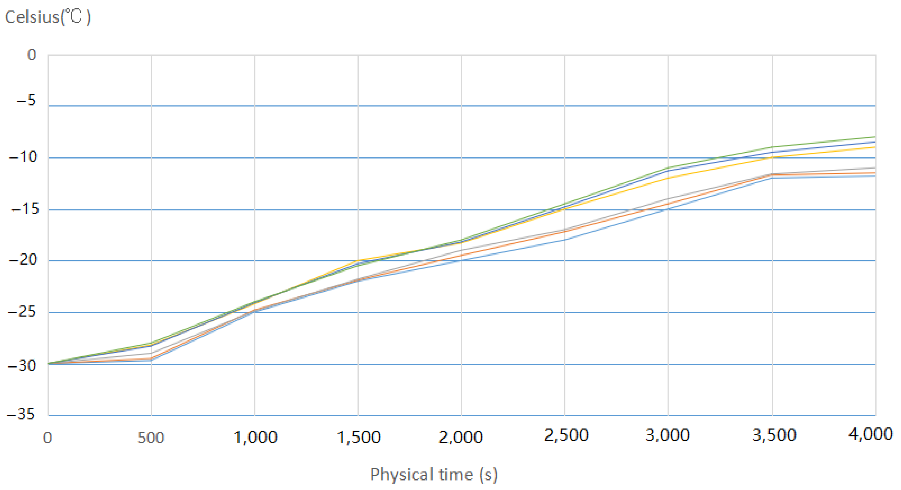
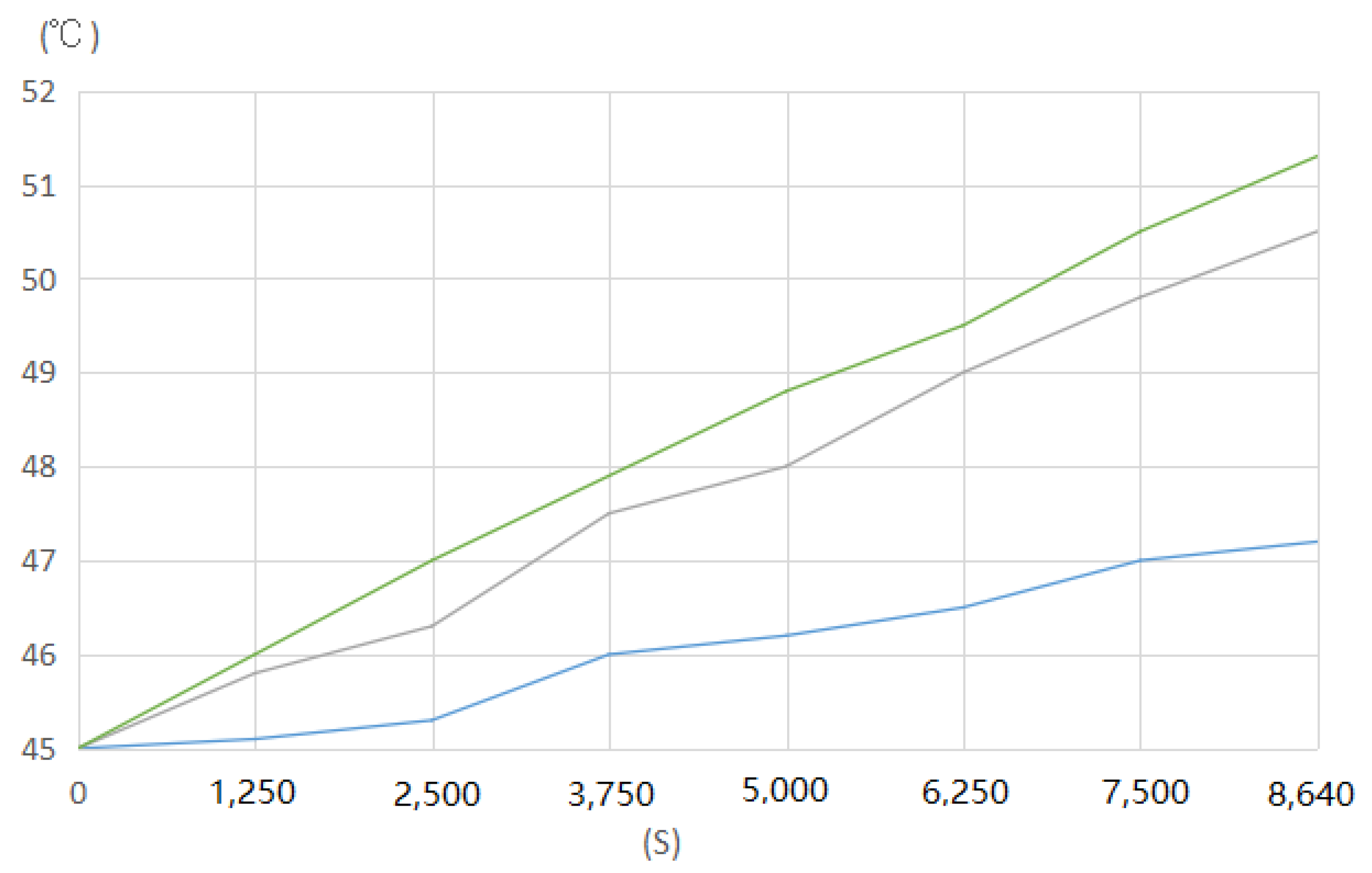
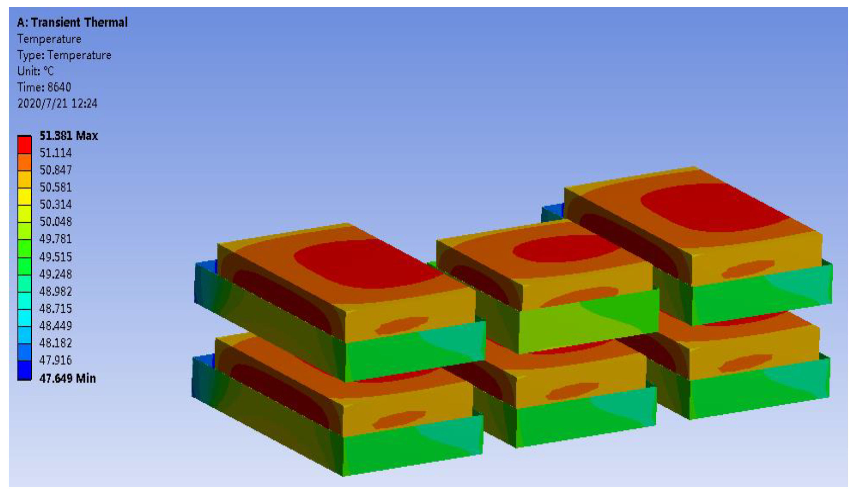
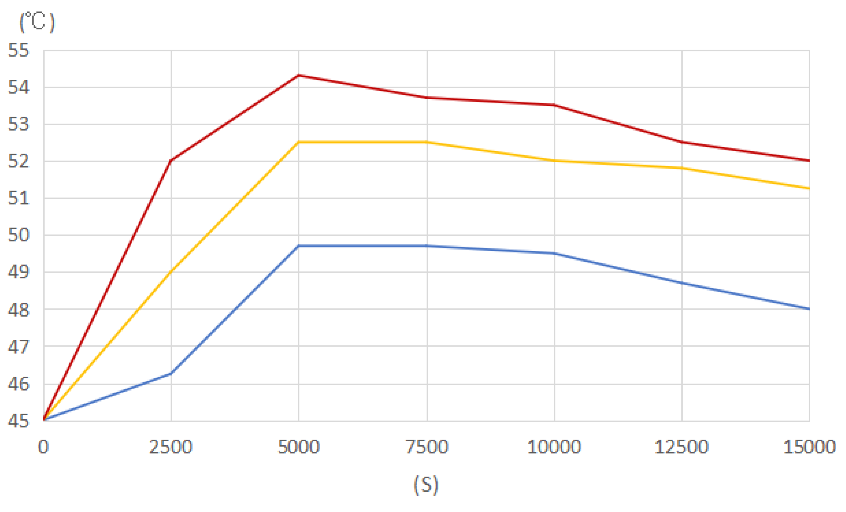
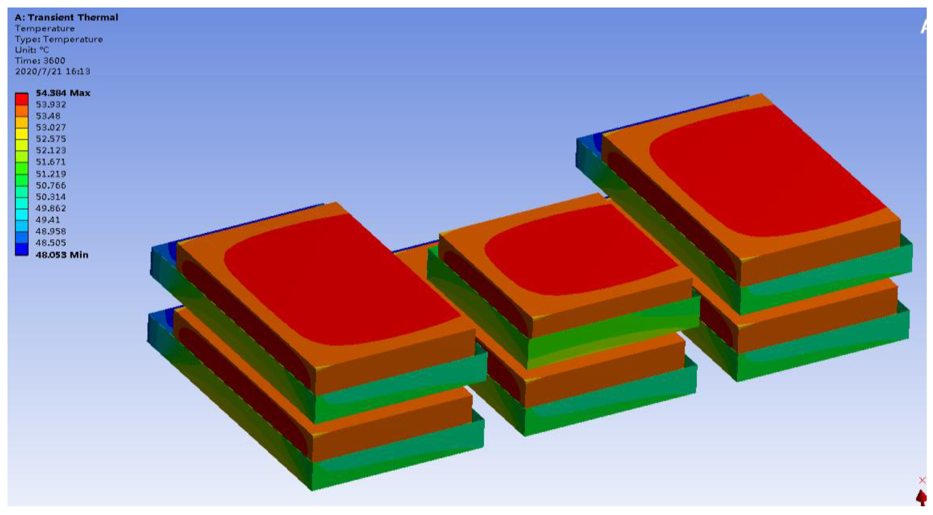
4.3. Thermal Simulation Analysis
- (1)
- Low-temperature heating condition
- (2)
- High-temperature charging condition
- (3)
- High-temperature discharge condition
4.4. Power Battery Box Test and Verification
4.5. Economic Comparison
5. Discussion
6. Conclusions
- (1)
- The optimized scheme raised the protection level of the power battery box from the original IP56 to IP68, and the scheme passed the test verification by meeting the standard Q/CRRC J 37.1-2019. This shows that in the optimization scheme, the aluminum metal shell, as the first level of protection, is reasonable and effective, fulfills the role of the protective cell, and reaches the protection level of IP68.
- (2)
- For the batteries in this study, the natural air cooling scheme can control the overall temperature rise of the battery within the 15 °C stipulated by the standard under low-temperature heating, high-temperature charging and high-temperature discharge conditions; therefore, this scheme is feasible. The air conditioner scheme can be completely substituted by the natural air cooling scheme, with the system weight decreased by 450 kg and a cost savings of CNY 11,700.
- (3)
- Through the design and research of the power battery two-stage protective box, the contradiction between high-level protection needs and natural air cooling needs is solved, and a new design concept for a locomotive power battery system is provided.
Author Contributions
Funding
Acknowledgments
Conflicts of Interest
References
- The 14th Five-Year Plan for Railway Science and Technology Innovation. Railw. Tech. Superv. 2022, 50, 9–15+20.
- Chatterjee, K. Characteristics and Thermal Behavior Analysis of Lithium-Ion Batteries for Application in Hybrid Locomotives; Northern Illinois University: Chicago, IL, USA, 2022; pp. 51–64. [Google Scholar]
- Kolpakhchyan, P.G.; Evstaf’ev, A.M.; Nikitin, V.V.; Zarifyan, A.A.; Talakhadze, T.Z. Design Features of a Contact-Battery Shunting Electric Locomotive. Russ. Electr. Eng. 2021, 92, 555–560. [Google Scholar] [CrossRef]
- Iden, M.E. Battery Electric Locomotives & Battery Tenders: Operational & Infrastructure Challenges to Widespread Adoption. In Proceedings of the ASME/IEEE Joint Rail Conference, Online, 20–21 April 2021; American Society of Mechanical Engineers: New York, NY, USA, 2021; Volume 84775, p. V001T07A003. [Google Scholar]
- Wongthong, Y.; Rattanapanyalert, T.; Supopat, T.; Techawatcharapaikul, C. A Design of Energy Storage System for Electric Locomotive. In Proceedings of the 2021 9th International Electrical Engineering Congress, Pattaya, Thailand, 10–12 March 2021; IEEE: New York, NY, USA, 2021; pp. 149–152. [Google Scholar]
- Wu, J.; Ji, Q.; Zhang, C.; Zhu, Z.; Zhao, B.; Yin, Z. Design and Modeling of Diesel-Electric Hybrid Shunting Locomotive. In The Proceedings of the 9th Frontier Academic Forum of Electrical Engineering; Springer: Singapore, 2021; pp. 655–665. [Google Scholar]
- An, Y.; Wang, X.; Dou, N.; Wu, Z. Strength analysis of the lightweight-designed power battery boxes in electric vehicle. In Proceedings of the 2022 7th International Conference on Green Materials and Environmental Engineering, Changsha, China, 16–17 January 2022; pp. 147–153. [Google Scholar]
- Weigao, Q.; Zhanxi, Z.; Dong, L.; Lei, Y. Study on Side Collision of Battery Boxes Based on HyperWorks. J. Phy. Conf. Series 2021, 2137, 012012. [Google Scholar]
- Ding, Q.; Wang, J.; Liu, G.; Yao, B.; Jiang, G.; Du, Q. Research on Safety Design of Protection Box for Emergency Standby Power Supply System of High Speed EMU. Chin. Battery Ind. 2019, 23, 44–49. [Google Scholar]
- Peng, C.; Wang, P.; He, G. Research on Safety Design Technology of High-power Lithium Ion Traction Battery System for Locomotive and EMU. Electr. Drive Locomot. 2020, 5, 123–127. [Google Scholar] [CrossRef]
- Zhang, X.; Zhou, F.; Feng, Q.; He, J. Design of Carbon Fiber Box. Shanghai Automob. 2014, 9, 60–62. [Google Scholar]
- Li, J.; Tian, H.; Wu, P. Analysis of random vibration of power battery box in electric vehicles. In Proceedings of the 2014 IEEE Conference and Expo Transportation Electrification Asia-Pacific, Beijing, China, 31 August 2014–3 September 2014; IEEE: New York, NY, USA, 2014; pp. 1–5. [Google Scholar]
- Chen, Q.S.; Zhao, H.; Kong, L.X.; Chen, K.W. Research on Battery Box Lightweight Based on Material Replacement. In Proceedings of the 2017 5th International Conference on Mechatronics, Materials, Chemistry and Computer Engineering, Chong Qing, China, July 24–25; Atlantis Press: Paris, France, 2017; pp. 346–358. [Google Scholar]
- Meng, Y.; Gao, X.; Ye, D. Optimal Design of HXN6 Hybrid Shunting Locomotive Power Battery Group Structure. Railw. Locomot. Car 2021, 41, 99–104. [Google Scholar]
- Liu, B.; Kang, M.; Xing, T. Hybrid shunting locomotive design exported to German. Railw. Qual. Control. 2019, 47, 43–47+59. [Google Scholar]
- Xie, J.; Liu, L. Electrical system design of a certain hybrid electric locomotive. Technol. Mark. 2021, 28, 15–18. [Google Scholar]
- Hu, L. Analysis of the development route of thermal support system for locomotive power battery. Technol. Mark. 2020, 27, 49–50+52. [Google Scholar]
- Taguchi, Y.; Kadowaki, S.; Yoshikawa, G.; Hatakeda, K.; Kaneko, T. Control method for cooling fans inside traction battery boxes installed in battery powered EMU based on thermal network model. Electr. Eng. Japn. 2021, 2, 23310. [Google Scholar] [CrossRef]
- Yue, Q.L.; He, C.X.; Wu, M.C.; Xu, J.B.; Zhao, T.S. Pack-level modeling of a liquid cooling system for power batteries in electric vehicles. Int. J. Heat Mass Transf. 2022, 192, 122946. [Google Scholar] [CrossRef]
- Zhao, J. Research on Thermal Management System of Electric Vehicle Power Battery Pack. Acad. J. Eng. Technol. Sci. 2020, 34, 62–74. [Google Scholar]
- Wenwei, W.; Cheng, L.; Peng, T.; Chengjun, Z. Thermal characteristic analysis of power lithium-ion battery system for electric vehicle. In Proceedings of the 2012 Third International Conference on Digital Manufacturing & Automation, Guilin, China, 31 July 2012–2 August 2012; IEEE: New York, NY, USA, 2012; pp. 967–971. [Google Scholar]
- Xiang, L.; Cui, J. Simulation analysis of air cooling for vehicle power battery. J. Phys. Conf. Ser. 2018, 1064, 012007. [Google Scholar] [CrossRef]
- GB 4208-2008; Degrees of Protection Provided by Enclosure (IP code). Standards Press of China: Beijing, China, 2008. Available online: https://www.antpedia.com/standard/5639827-1.html (accessed on 6 October 2022).
- Wandong, X. Research and Application of the New Energy Vehicle Power System IP68 Air Tightness Detection Method; East China Jiaotong University: Huichang, China, 2019. [Google Scholar]
- Zhang, G.; Zhou, X.; Liang, K.; Guo, B.; Li, X.; Wang, Z.; Zhang, L. Mechanically robust and recyclable EPDM rubber composites by a green cross-linking strategy. ACS Sustain. Chem. Eng. 2019, 7, 11712–11720. [Google Scholar] [CrossRef]
- Wang, Z.N.; Shen, S.L.; Zhou, A.N.; Xu, Y.S. Experimental evaluation of aging characteristics of EPDM as a sealant for undersea shield tunnels. J. Mater. Civ. Eng. 2020, 32, 04020182. [Google Scholar] [CrossRef]
- Gang, S.; Shihao, W.; Xuesen, C.; Chengxiao, R. Post-fire mechanical properties of base metal and welds of Q235 steel. J. Constr. Steel Res. 2021, 183, 106767. [Google Scholar]
- EN15085: 2020; Railway Applications—Welding of Railway Vehicles and Components—Part 2: Requirements for Welding Manufacturer. Estonian Centre for Standardisation and Accreditation: Tallin, Estonia, 2020. Available online: https://www.evs.ee/en/evs-en-15085-2-2020 (accessed on 6 October 2022).
- Xu, Y.; Zhang, Y.; Liu, B. Key elements and common problems in EN 15085 welding system running. Electr. Weld. Mach. 2020, 50, 132–135. [Google Scholar]
- Zhao, C.; Guo, C. Type HXN3B (4400 HP) AC transmission shunting diesel locomotive battery box design. Sci. Technol. Vis. 2017, 5, 2095–2457. [Google Scholar]
- Wang, K.; Pan, H.Y.; Zhang, T.J.; Wang, H.T. Experimental study on the radial vibration characteristics of a coal briquette in each stage of its life cycle under the action of CO2 gas explosion. Fuel 2022, 320, 123922. [Google Scholar] [CrossRef]
- Wang, K.; Pan, H.; Zhang, T.J. Experimental Study of Prefabricated Crack Propagation in Coal Briquettes under the Action of a CO2 Gas Explosion. ACS Omega 2021, 6, 24462–24472. [Google Scholar] [CrossRef]
- Zheng, T. The Finite Element Analysis and Structure Optimize of Railway Vehicle Battery Box against Shock Vibration; Jilin University: Jilin, China, 2015. [Google Scholar]
- Q/CRRC J 37.1-2019; Test Methods for Onboard Energy Storage System of Railway Transportation Equipment—Part 1: Power Battery System. ITS China: Tianjin, China, 2019.
- GB/T21563-2018; Railway Applications-Rolling Stock Equipment-SHOCK and Vibration Tests. National Railway Administration of People’s Republic of China: Beijing, China, 2018.


| Version | Density (g/cm3) | Modulus of Elasticity (E/GPa) | Poisson Ratio | Tensile Strength (MPa) | Yield Strength (MPa) |
|---|---|---|---|---|---|
| Q235 | 7.85 | 200~210 | 0.25~0.33 | 370~500 | 235 |
| Order | Frequency (Hz) | Mode of Vibration |
|---|---|---|
| 1 | 47.932 | Movement in the forward or backward direction of the locomotive. |
| 2 | 54.806 | Shaking up and down vertically compared to the horizontal plane. |
| 3 | 62.403 | Shaking up and down vertically compared to the horizontal plane. |
| 4 | 62.831 | Swinging perpendicular to the locomotive’s running direction. |
| 5 | 67.978 | Swinging perpendicular to the locomotive’s running direction. |
| Item Point Name | Data |
|---|---|
| Self-load maximum stress | 34.54 MPa (truss) |
| Longitudinal load maximum stress | 128.4 MPa (primary beam) |
| Lateral load maximum stress | 124.6 MPa (crutch) |
| Max. self-load deformation | 0.45 mm (truss) |
| Max. longitudinal load deformation | 0.93 mm (truss) |
| Max. lateral load stress | 0.93 mm (truss) |
| Mode frequency range | 47.932–67.978 Hz |
| Fatigue load factor | 3.75 |
| Simulation Condition | Details |
|---|---|
| Initial temperature | Ambient temperature −30 °C; Battery temperature −30 °C |
| Working condition | Heating of the film |
| Duration | 3600 s |
| Simulation Condition | Details |
|---|---|
| Initial temperature | Ambient temperature 45 °C; Battery temperature 45 °C |
| Working condition | 0.3 C charging, 80% state of charge;the total calorific value of the battery cabinet is 946 W |
| Duration | 8640 s |
| Simulation Condition | Details |
|---|---|
| Initial temperature | Ambient temperature 45 °C; battery temperature 45 °C |
| Working condition | Discharge for 1 h and stand for 3 h, 0.7 C (230 A) discharge 1 h; total heat power: 3250 W |
| Duration | 15,000 s |
| Number | Inspecting Item | Standard | Result | Conformance Determination |
|---|---|---|---|---|
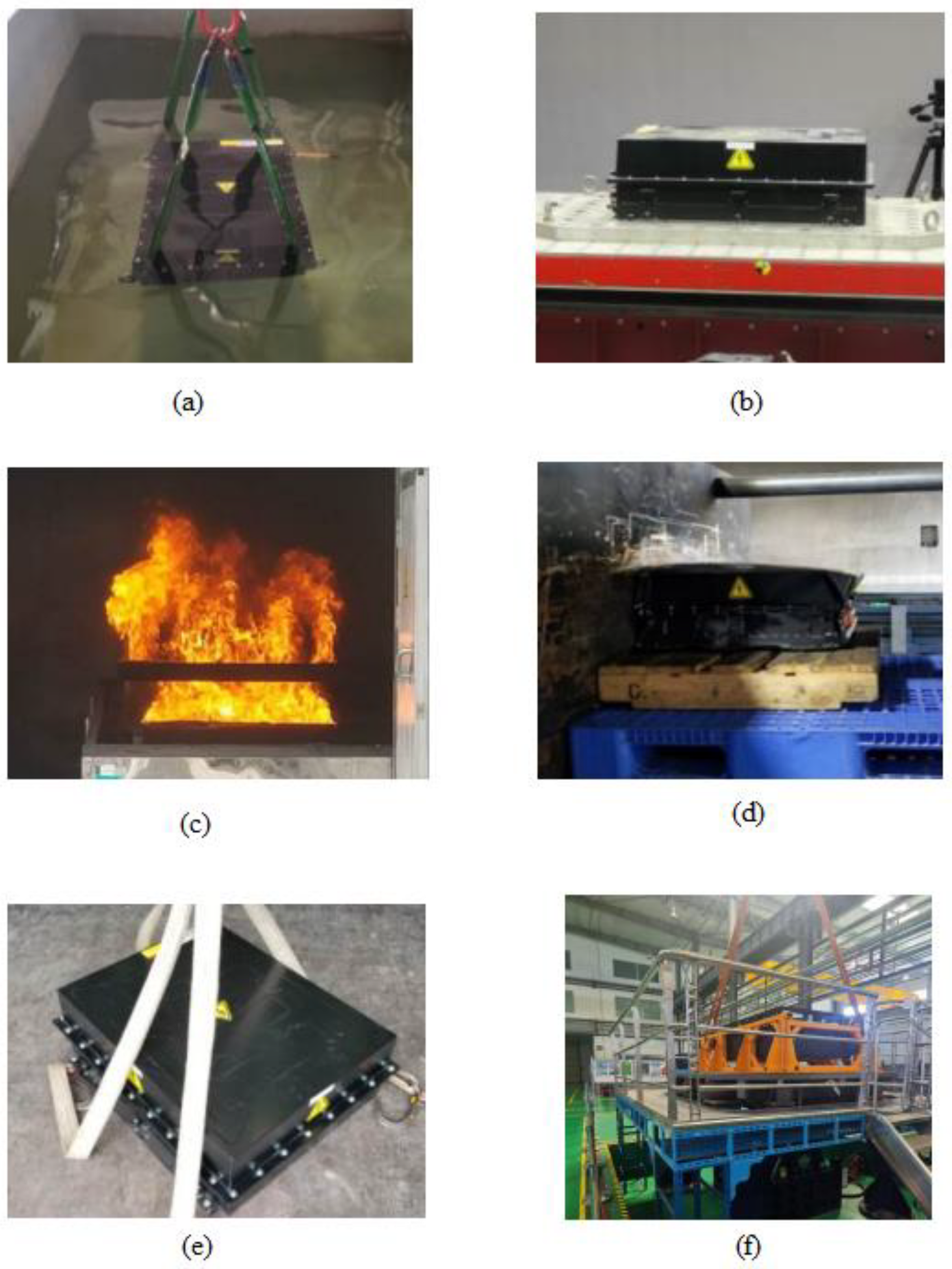
| 1 | Seawater immersion | Q/CRRC J 37.1-2019 | All the indicators of the sample are within the boundaries of the test (Figure 20a). | Yes |
| 2 | Salt mist | Q/CRRC J 37.1-2019 | There was no leakage, fire, or explosion during the test process (Figure 20b). | Yes |
| 3 | External fire | Q/CRRC J 37.1-2019 | There was no leakage, fire, or explosion during the test process (Figure 20c). | Yes |
| 4 | Squeeze | Q/CRRC J 37.1-2019 | The sample exhibited no fire or explosion during the test process (Figure 20d). | Yes |
| 5 | Simulation collision | Q/CRRC J 37.1-2019 | All the indicators of the sample are within the boundaries of the test (Figure 20d). | Yes |
| 6 | Depreciation | Q/CRRC J 37.1-2019 | All the indicators of the sample are within the boundaries of the test (Figure 20e). | Yes |
| 7 | Vibration test | GB/T21563-2018 | The tested object maintains a reliable connection and an intact structure, with no leakage, shell rupture, fire, or explosion phenomenon (Figure 20f). | Yes |
| 8 | Impact test | GB/T21563-2018 | The tested object maintains a reliable connection and intact structure, with no leakage, shell rupture, fire, or explosion phenomenon (Figure 20f). | Yes |
| Item Point Name Box Type | Two-Stage Protective Box | One-Stage Protective Box |
|---|---|---|
| Cooling method | Natural air cooling | Air conditioner air cooling |
| Box volume (m3) | 1.49 | 1.93 |
| Cooler cost (CNY) | 0 | 3500 |
| Box manufacturing cost (CNY) | Raw material: 28,000 Accessory: 5000 Machining: 23,000 Transport: 800 Total: 56,800 | Raw material: 30,000 Accessory: 5000 Machining: 28,800 Transport: 1200 Total: 65,000 |
| Complete machine maintenance consumed working hours | 4.5 | 6.5 |
| Weight (kg) | 2020 | 2470 |
Publisher’s Note: MDPI stays neutral with regard to jurisdictional claims in published maps and institutional affiliations. |
© 2022 by the authors. Licensee MDPI, Basel, Switzerland. This article is an open access article distributed under the terms and conditions of the Creative Commons Attribution (CC BY) license (https://creativecommons.org/licenses/by/4.0/).
Share and Cite
Dong, S.; Lv, J.; Wang, K.; Li, W.; Tian, Y. Design and Optimization for a New Locomotive Power Battery Box. Sustainability 2022, 14, 12810. https://doi.org/10.3390/su141912810
Dong S, Lv J, Wang K, Li W, Tian Y. Design and Optimization for a New Locomotive Power Battery Box. Sustainability. 2022; 14(19):12810. https://doi.org/10.3390/su141912810
Chicago/Turabian StyleDong, Sihui, Jinxiao Lv, Kang Wang, Wanjing Li, and Yining Tian. 2022. "Design and Optimization for a New Locomotive Power Battery Box" Sustainability 14, no. 19: 12810. https://doi.org/10.3390/su141912810
APA StyleDong, S., Lv, J., Wang, K., Li, W., & Tian, Y. (2022). Design and Optimization for a New Locomotive Power Battery Box. Sustainability, 14(19), 12810. https://doi.org/10.3390/su141912810