Article

Study on Evolution of Front Abutment Pressure at Working Face in Repeated Mining of Close-Distance Coal Seams

1
School of Energy and Mining Engineering, China University of Mining and Technology (Beijing), Beijing 100083, China
2
Beijing Key Laboratory for Precise Mining of Intergrown Energy and Resources, China University of Mining and Technology (Beijing), Beijing 100083, China
3
Department of Civil Engineering, Lakehead University, Thunder Bay, ON P7B5E1, Canada
4
College of Energy and Mining Engineering, Shandong University of Science and Technology, Qingdao 266590, China
*
Author to whom correspondence should be addressed.
Sustainability 2022, 14(19), 12399; https://doi.org/10.3390/su141912399
Submission received: 26 July 2022 / Revised: 25 September 2022 / Accepted: 27 September 2022 / Published: 29 September 2022

Abstract

:
In order to determine the reasonable width of a stopping coal pillar in close-distance coal seams, the evolution law of front abutment pressure of the working face with repeated mining was studied. Based on the actual engineering project, we conducted field measurement, theoretical analyses, numerical simulations and a physical similarity simulation test to study. The results show that: (1) according to field measurement, the influence range of front abutment pressure increases from 60 m to 75 m with repeated mining; (2) according to theoretical analysis, the arch height and span are negatively and positively correlated with the influence range of front abutment pressure, respectively; (3) with repeated mining, the arch height increased to 165 m, the arch span to 235 m and the influence range to 83.5 m by 14.5 m relative to that before repeated mining; (4) if it is necessary to ensure that the main roadway is less affected by the mining stress, the width of the stopping coal pillar in 2214 working face should be greater than 80 m. The influence range of front abutment pressure increases obviously with repeated mining in close-distance coal seams. The study provides a reference for similar engineering projects.

1. Introduction

In coal mining, a main roadway typically has a long lifespan; hence, its surrounding rock must be stable. However, mining-induced stress primarily affects main roadway stability. The coal pillar from the end of the working face to the main roadway is referred to as the stopping coal pillar. If the width of this pillar is too large, coal resources would be wasted during mining; if the width is too small, mining-induced stress would disturb the main roadway. Meanwhile, when the stopping coal pillar bears high abutment pressure, there will be a lot of cracks [1,2,3,4], which will affect the stability of the stopping coal pillar, further causing potential safety hazards to the main roadway. The influence range of front abutment pressure at a working face considerably influences the width of the stopping coal pillar. Studies have been conducted on the abutment pressure distribution of the working face in a single coal seam, but only a few studies have considered this phenomenon for close-distance coal seams. Likewise, only a few studies have investigated the evolution of the influence range of the working face front abutment pressure when the stable three-zone distribution of upper coal seam mining changes after repeated mining. Hence, it is crucial to study the evolution behavior of the influence range of the working face front abutment pressure in this type of close-distance coal seams.
Many scholars have carried out research on the stability of the main roadway. C.J. Gao established the matter–element model of rock mass accident risk assessment in a deep roadway by combining hazard source theory with the extension method [5]. Y. Luo analyzed the stability of the surrounding rock in a deep roadway [6]. C.X. Zhao studied the surrounding rock control technology of deep soft rock roadway [7]. H. Wang analyzed deformation and the failure mechanism of the surrounding rock using field monitoring and borehole imaging methods [8]. Some scholars have also studied the stability of surrounding rock [9,10,11].
Many scholars have carried out much research on the influence range of front abutment pressure at the working face. M.G. Qian analyzed different the peak values and the influence range of front abutment pressure when there are different types of key strata in the overlying strata [12]. Starting from the mechanism, Z.Q. Song proposed a new method for calculating abutment pressure [13]. S.T. Zhu proposed a theoretical computational model of abutment pressure of ETAS longwall panels based on the analysis of load transfer mechanisms of the key stratum [14]. Y.G. Ji studied the distribution law of front abutment pressure via theoretical calculation and numerical simulation [15]. J.L. Xie investigated the effect of the key stratum on the mining abutment pressure of a coal seam using UDEC [16]. Y. Li studied the law of abutment pressure when a longwall panel passes through the abandoned roadway in a damaged coal seam [17]. A. Li proposed an analytical model to simulate the front abutment pressure distribution under elastic and inelastic conditions [18]. P.S. Zhang tested the distribution characteristics of the front abutment pressure based on distributed optical fiber sensing technology and theoretical analysis of the stress state [19]. J.H. Liu established a calculation model of dynamic and static abutment pressure based on the abnormal strata behaviors of a number of cases [20]. D.J. Xue introduced damage based on internal friction angle or cohesion into the plastic region to consider discontinuity and applied it to solve the distribution of discontinuous abutment pressure [21]. H.K. Han established a method based on the influence of the overburden KS to calculate the abutment pressure of the coal mass and the goaf [22].
Many scholars have carried out varied research on the overburden stress arch above the working face. L. Wang suggested that the overburden of the working face will form a stress shell and that there is a two-dimensional stress arch along the strike of the working face [23]. F. Wang established a mechanical model for elucidating the formation mechanism of the stress arch in overlaying strata and studied the evolution of the stress arch during longwall mining through numerical simulation [24]. S.R. Wang established mechanical models of the symmetrical pressure-arch, the stepped pressure-arch and the rotating-squeezed stress arch in the mining field [25]. B.W. Xia established a mechanical model to investigate the propagation laws of hydraulic fracture based on the stress arch theory [26]. S.R. Wang established a mechanical model of the surrounding rock for studying the law of ground pressure based on the monitoring data of mine pressure [27]. Y.H. Zhao analyzed the pressure arching effect of the hanging roof blocks [28]. C.Y. Jin verified the stress arch theory for the failure mechanism of a highly stressed rock mass during unloading [29]. M.D. Yang established the structural model of the overlying strata pressure arch based on the theory of the pressure arch and key stratum [30]. Y.H. Zhao proposed the arching index of compressive stress of key parts of the pressure arch in far-field surrounding rock by discussing the active released state of vertical pressure and the vertical stress distribution characteristics of overlying strata under the influence of deviation of the principal stress axis [31]. Z. Zhu studied the side abutment pressure of the working face through stress arch theory [32].
Therefore, it is currently difficult to provide a scientific basis for determining the width of the stopping coal pillar in close-distance coal seams. In this study, we established a mechanical model, for the stress arch under a nonlinear load to solve the analytical equation of front abutment pressure, and a numerical simulation. A physical similarity simulation test was conducted to determine the evolution of the influence range of front abutment pressure in close-distance coal seams. This study will provide a scientific basis for determining the width of the stopping coal pillar under similar geological conditions.

2. Project Overview

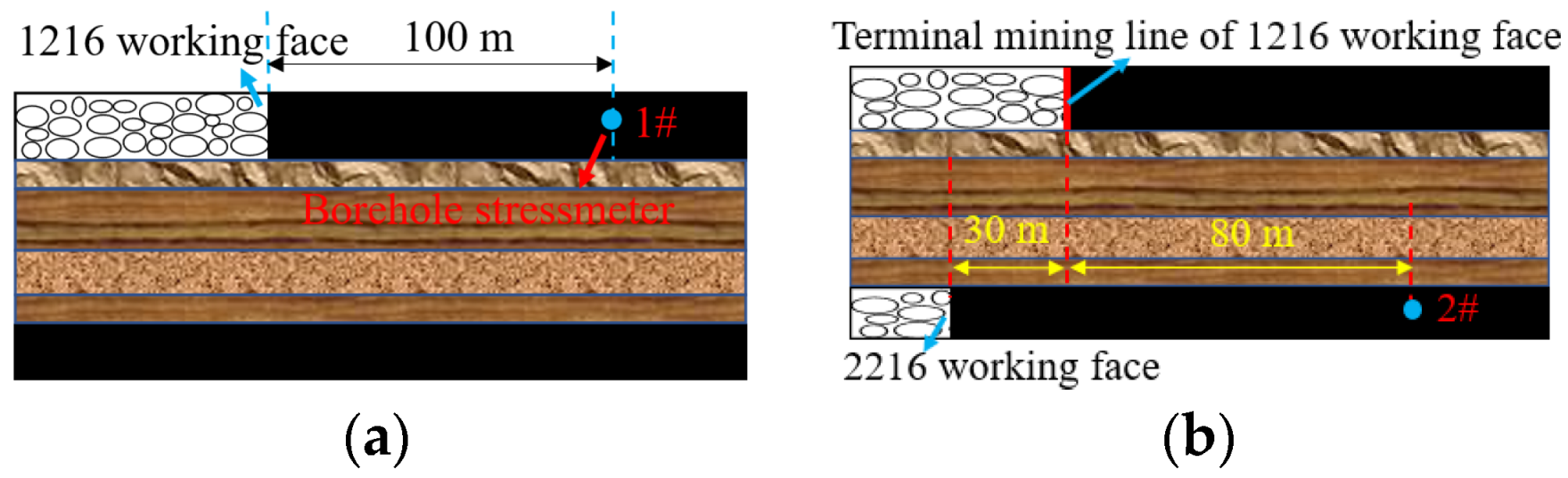
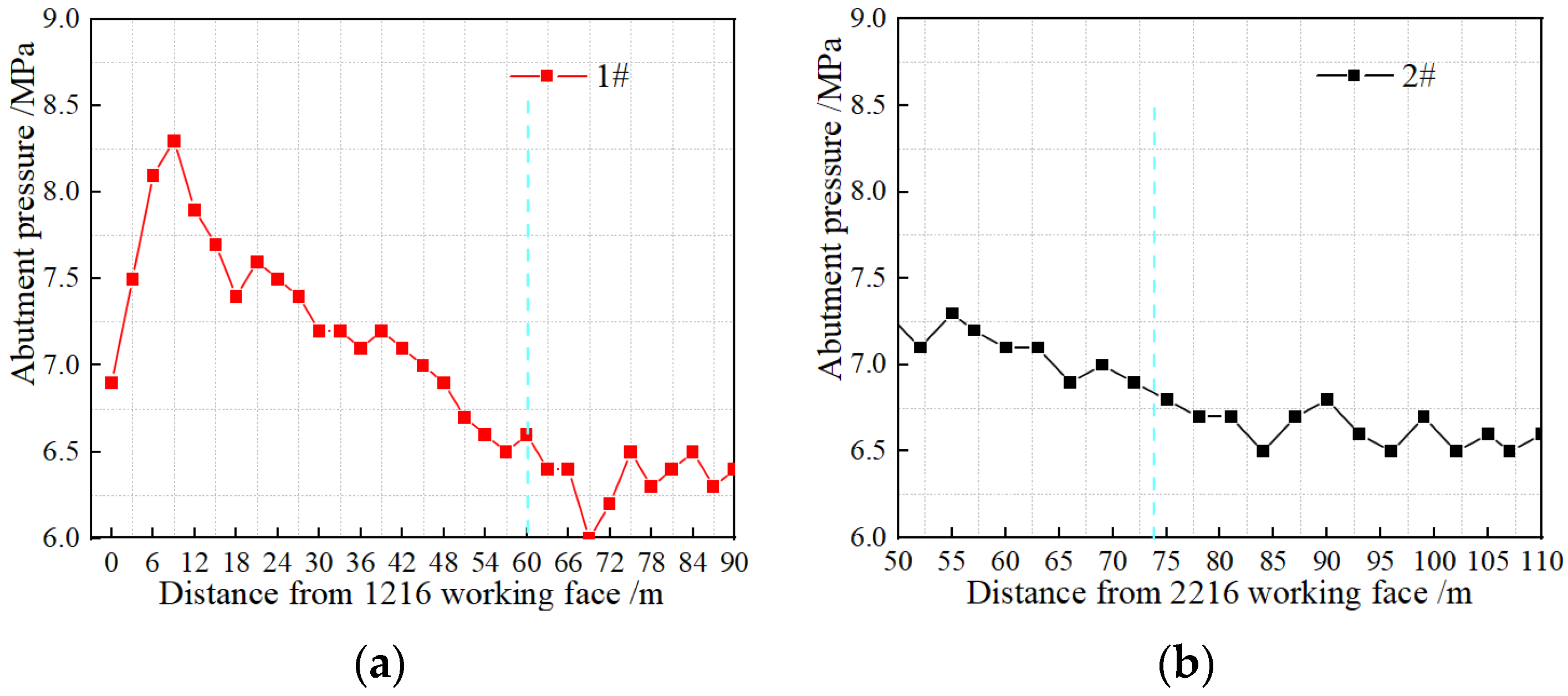
2.1. Engineering Background

Yan Coal Mine is located in Datong Coalfield, Shanxi Province, China, and has low gas content and simple hydrogeological conditions. The selected upper and lower coal seams were the No. 1 and No. 2 coal seams of the Yan Coal Mine and had a thickness of 7.5 m and 5.5 m, respectively. Both coal seams had an average seam spacing of 25 m, which is typical of close-distance coal seams. The 1216 and 2216 working faces are the first working face of No. 1 and No. 2 coal seams, respectively. To the south of the 1216 working face is the 1214 working face, the widths of the stopping coal pillars are 200 m and 110 m respectively and the collapsed gangue in the goaf has been compacted. The width of the stopping coal pillar of the 2216 working face is about 55 m, and the 2214 working face is in the mining stage. Wide coal pillars are used between the working faces to protect the mining roadway, and the length of the working face is 170–190 m. The plane layout of working faces is shown in Figure 1. We used the downward mining and fully mechanized top coal caving longwall mining method as well as the roof span management method. The average daily working face mining of the two coal seams was 4 to 5 m in depth. The close-distance coal seams had simple roof and floor conditions. Figure 2 shows the rock stratum histogram.
However, slight pulp peeling and steel strip extrusion phenomena were observed in the main roadway near the 2216 working face after the 2216 working face mining stopped. Therefore, the technicians of the coal mine conducted intensive support for the position of ground pressure appearance. Figure 3 illustrates these phenomena. It indicates that the main roadway is disturbed by mining stress.
In practical projects, it is very important to ensure safety [33,34]. The 2214 working face needs to determine a reasonable width of the stopping coal pillar. Because the width of the stopping coal pillar in the 1214 working face is about 110 m, if the width of the stopping coal pillar in the 2214 working face is too small, more significant ground pressure may occur in the surrounding rock of the main roadway under mining stress disturbance with repeated mining. The determination of the width of the stopping coal pillar is mainly based on the influence range of the front abutment pressure of the working face. During the mining of the 1216 and 2216 working faces, the coal mine technicians measured the front abutment pressure.
Borehole stressmeters (1#, 2#) were arranged in the 1216 and 2216 working faces to determine the influence range of front abutment pressure of both working faces. Figure 4 and Figure 5 illustrate the device layout and borehole stressmeters monitoring data, respectively.
As is shown in Figure 5, the blue line marks the position where the abutment pressure begins to increase. The influence range of the front abutment pressure of the 1216 working face during mining was approximately 60 m, and that of the 2216 working face was approximately 75 m larger than that of the 1216 working face after repeated mining. Therefore, in order to determine the reasonable width of the stopping coal pillar in the 2214 working face, it is necessary to further study the evolution law of the abutment pressure with repeated mining of the close-distance coal seams.

2.2. Phenomena Analysis

Normal coal production was unaffected despite the slurry peeling off and steel strip extrusion phenomena observed in the main roadway. However, it is crucial to investigate the evolution of the influence range of the working face front abutment pressure after the repeated mining of close-distance coal seams, as mentioned in Section 2.1.
According to the stress arch theory, the overlying rock layer forms a macroscopic stress shell consisting of high stress bundles, which change dynamically as working face mining progresses; the overlying rock layer also forms a stress arch structure along the strike profile of the working face. The stress arch height is essentially equal to the fracture zone height. The front and rear arch feet of the stress arch are located in the nonmining coal body and open-off cut of the working face, respectively. The arch span is the distance between the inner boundary of the front and rear arch feet. It is assumed that when the working face mining reaches the full mining of the strike, the lower coal seam open-off cut becomes an alternate exterior layout. Figure 6 illustrates the shape of the stress arch of the close-distance coal seams, where L is the stress arch span, m; C is the working face mining distance, m; Sp is the plastic zone width, m; and h is the arch height of the stress arch, m [23].
The load exerted by the arch body is transmitted from the front arch foot to the front of the working face, forming an elastic pressurization zone. The inner boundary of the front arch foot is the elastic–plastic junction, while the outer boundary is at the boundary between the elastic pressurization zone and original rock–stress zone. Figure 7 illustrates the front arch foot of the stress arch.
According to the conservation of stress, the stress will not disappear or increase. Repeated mining may cause changes in the three stable zones after the upper coal seam mining while the fault zone increases. These phenomena alter the stress arch shape, increasing the influence range of the front abutment pressure in repeated mining.
Equation (1) can be used to judge whether repeated mining changes the distribution of the original three zones [35].
Δ = M h z ( K p z 1 ) h g ( K p g 1 )
where M is thickness of the No. 2 coal seam, 5.5 m; h z is thickness of the immediate roof, 11 m; K p z is bulking factor of the immediate roof, 1.25; h g is thickness of the interlayer key strata and follower layer, 14 m; K p g is bulking factor of the interlayer key strata and follower strata, 1.15; then, by Equation (1), we can calculate Δ = 0.65 .
The calculation results show that the geological conditions of the close-distance coal seams in the Yan Coal Mine meet the requirements in this study. Therefore, it is crucial to examine the evolution and mechanism of the influence range of the front abutment pressure in repeated mining for close-distance coal seams. This work would provide a scientific basis for determining the width of the stopping coal pillar.

3. Key Factors of Abutment Pressure in Repeated Mining

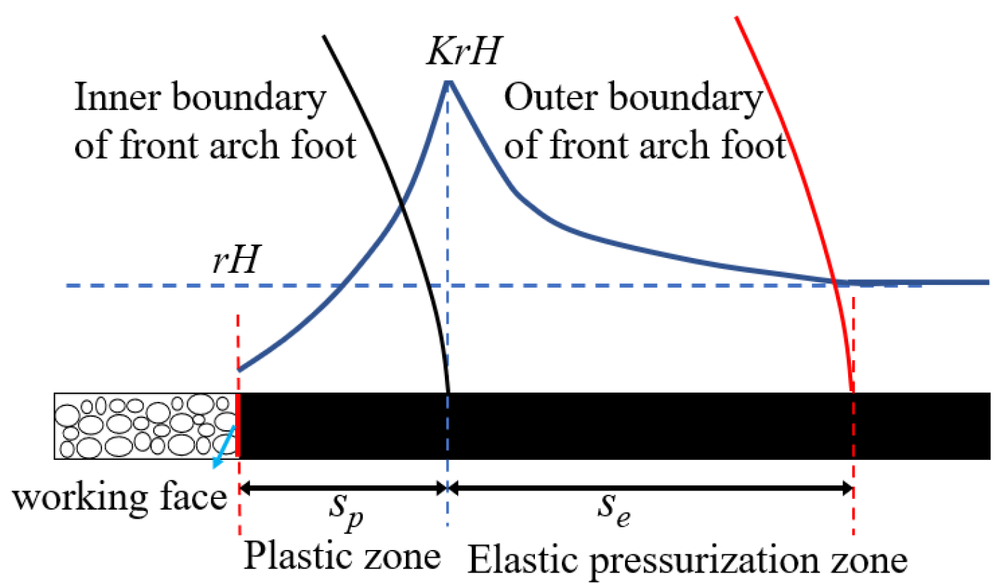
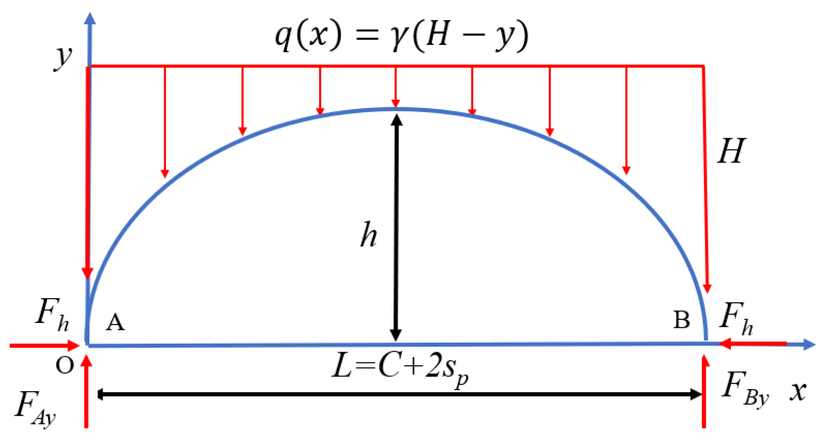
3.1. Stress Arch Equation under Nonlinear Load

Assuming the stress arch is symmetrical, and the front and rear arch feet are at the same level, the mechanical model can be established as illustrated in Figure 8.
According to the mechanical equilibrium conditions of stress arch [32]:
y ( x ) = M 0 ( x ) F h
q ( x ) = γ ( H y )
d 2 y d x 2 γ F h y = γ H F h
According to boundary conditions, x = 0 , y = 0 ; x = L 2 , d y d x = 0 ; and x = L , y = 0 ; therefore:
y = h H 2 ( A 2 x L 1 + A 2 x L + 1 ) + H
where A = H H h H 2 ( H h ) 2 1 ; F h is horizontal stress of the arch foot, kN; F A y and F B y are vertical stresses of the arch foot, kN; M 0 ( x ) is bending moment of the simply supported beam; q ( x ) is nonlinear load; γ is weight density of the rock, 25 KPa/m3; and H is coal seam buried depth, m.

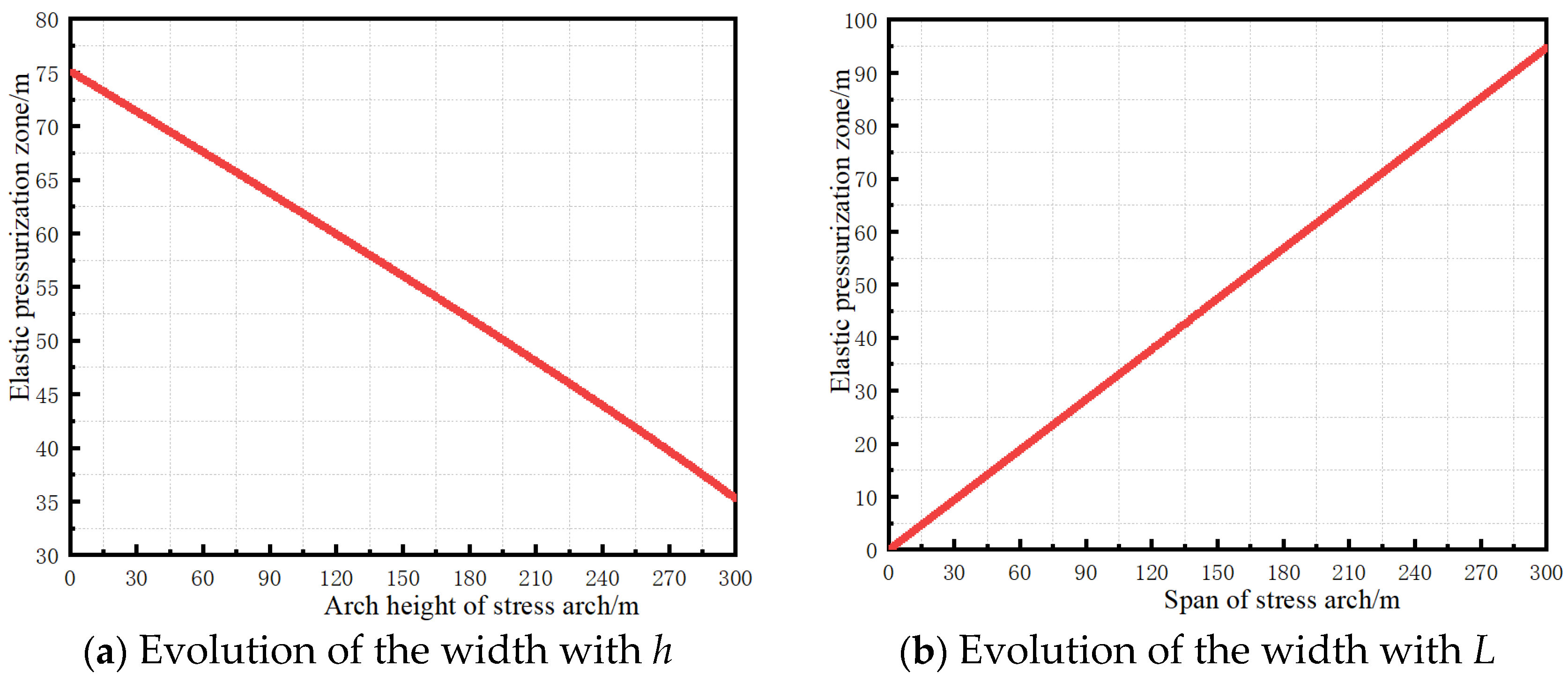
3.2. Abutment Pressure Distribution Calculation and Analysis of Key Factors

The vertical pressure at the front arch foot is:
F B y = 0 L 2 γ ( H y ) d x
The width of the plastic zone is:
s p = M 2 tan φ 0 1 sin φ 0 1 + sin φ 0 ln ( 1 sin φ 0 1 + sin φ 0 K γ H P x + c 0 tan φ 0 )
where M is coal seam thickness, m; c 0 is cohesion, 1 MPa; φ 0 is friction angle, radian, 29°; K is stress concentration factor, 4; and P x is coal wall support strength, 0 MPa. It can be seen from the engineering geological conditions that M of the 1214 working face is 7.5 m; then by Equation (7), we find s p of 1# coal seam is 8 m. M of the 2214 working face is 5.5 m; then by Equation (7), we find s p of 2# coal seam is 6.5 m. H is working face buried depth, 400 m.
Assuming the vertical stress distribution function in elastic pressurization zone is:
σ e y = γ H K s p s e + 1 e ln K s e x
According to stress equality, the width of elastic pressurization zone is:
F B y = s p s p + s e γ H K s p s e + 1 e ln K s e x γ H d x
s e = L h ( L 2 + 2 B 2 B 1 ) + L H ( 2 B 1 2 B ) 8 H ( 1 + l n K K )
where B = H + h ( 2 H h ) ( H h ) 2 h h ( 2 H h ) ( H h ) 2 H H h ; S e is the width of elastic pressurization zone.
The influence range of front abutment pressure of working face is:
L c = S e + S p
According to Equation (10), the width of the elastic pressurization zone is determined by H, h, L and K. As H and K are fixed, it is only necessary to discuss the influence of h and L.
Assuming the working face is fully mined along the strike, with H = 400 m, K = 4 and L = 175 m, the evolution of the width of the elastic pressurization zone with h can be obtained from Equation (10), as illustrated in Figure 9.
Setting H = 400 m, K = 4 and h = 165 m, the width evolution of the elastic pressurization zone with L can be obtained from Equation (10), as illustrated in Figure 10.
According to the illustration in Figure 9a and the increase in arch height, a decreasing trend is observed in the range of the elastic pressurization zone. During the 2214 working face mining, the fracture zone height continuously increases, while the elastic pressurization zone reduces, decreasing the influence range of the front abutment pressure. However, Figure 5 in Section 2.2 shows that the influence range of the front abutment pressure will increase with repeated mining. In fact, after repeated mining, the stress arch span also increases. The illustration presented in Figure 9b shows that the elastic pressurization zone range will increase linearly as L increases; hence, the influence range of the front abutment pressure is jointly determined by the size of h and L.

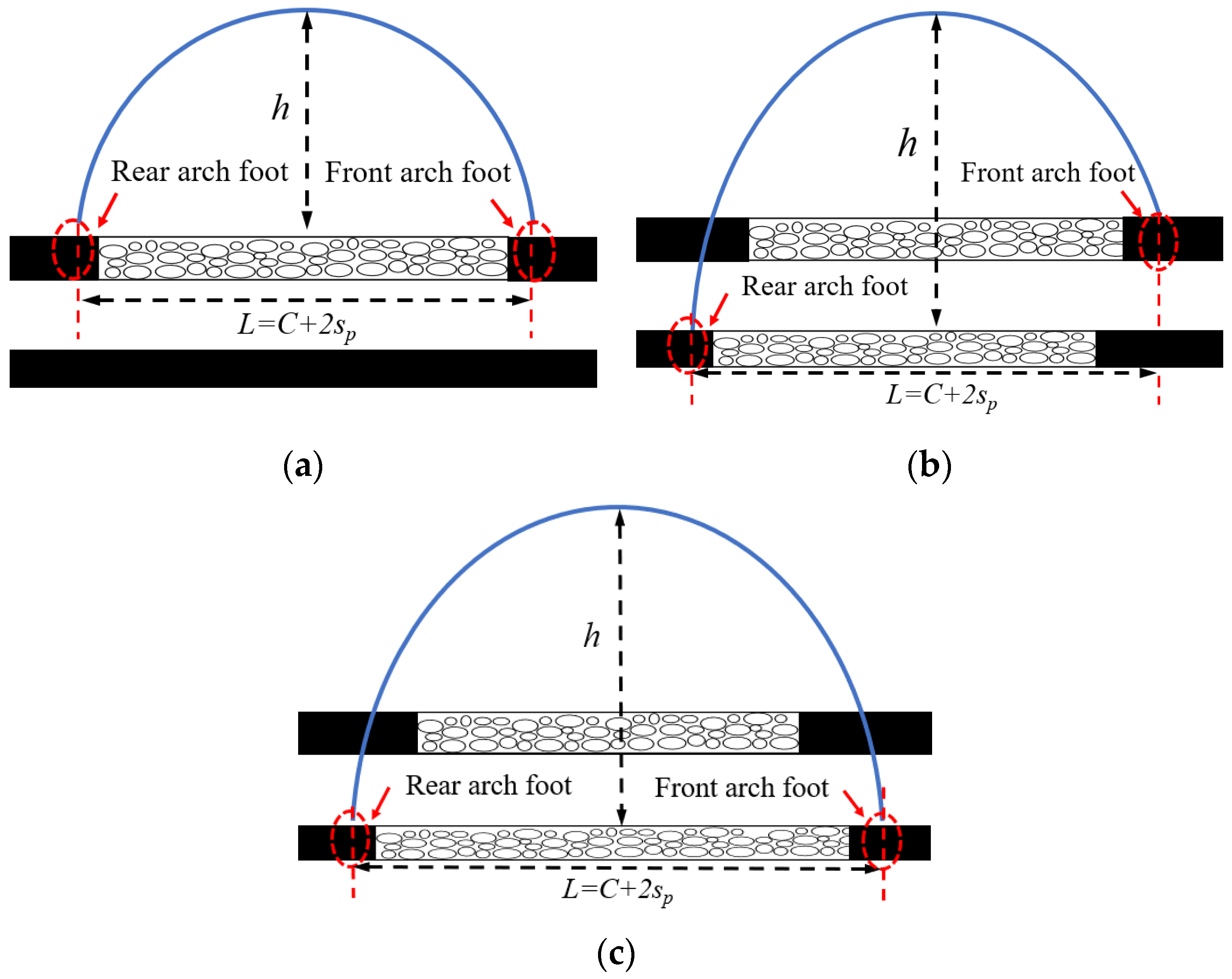
3.3. Method for Obtaining Shape Parameters of Stress Arch

With three complete zones after repeated mining, the stress arch crown is located in the bending subsidence zone and near the water conducted zone. The water conducted zone height can be obtained using relevant theories; however, it is difficult to examine the evolution process of the stress arch shape after repeated mining.
Numerical and physical similarity simulations are common methods used in engineering research [36,37,38]. Hence, we used these methods to study the shape evolution of the stress arch during the repeated mining of close-distance coal seams. Subsequently, we compared the values of h and L using a rock stratum histogram. The accuracy of the values was verified by the location of the stress arch crown in the key strata.

4. Evolution of Shape Parameters of Stress Arch in Repeated Mining

4.1. Numerical Simulation

4.1.1. Numerical Simulation Model Development

Numerical simulation is commonly used in scientific research [39]. We used the FLAC3D numerical simulation software to study the evolution of the stress arch height and span. According to the geological conditions of the 1214 and 2214 working faces, we established the numerical simulation model of the middle part along the working face inclination. The plane strain model size was 400 m (X) × 10 m (Y) × 250 (Z) m. The X-axis represented the strike direction of the working face. The displacement at the bottom, front, back, left and right of the model was minimal, and a vertical stress of 4.75 MPa was applied to the upper boundary of the model to simulate the overburden pressure. Vertical and horizontal stresses were applied according to the measured in situ stress, and the side pressure coefficient was 1.2. The working face was excavated from the left side to the right side of the model.
Mohr-Coulomb was adopted as the constitutive relation of the model. To obtain reliable numerical simulation results, it is necessary to accurately evaluate the mechanical properties of coal and rock mass. Hence, according to the literature [40,41,42,43], we set the coal and rock mass elastic modulus, cohesion and tensile strength as 0.25 times those of the laboratory test results, and the Poisson’s ratio was 1.2 times that of the laboratory test results. Table 1 presents the rock mechanical parameters.
The caving of gangue in the goaf is gradually compacted during the mining of the working face, which considerably increases the goaf stiffness and elastic modulus, forming a goaf compaction zone. To accurately analyze the evolution behavior of the stress arch during the mining of the working face, we used a double yield model to replace coal seam mining and simulate the caving of gangue in the goaf. The cap pressure in the double yield model was calculated using Equations (12)–(14) [44,45].
σ c a p = E 0 ε 1 ( ε / ε max )
ε max = K p 1 K p
E 0 = 10.39 σ c 1.042 K p 7.7
where σ c a p is the pressure on the gangue in the goaf; ε is the volume strain of the gangue in the goaf under the action of σ c a p ; ε max is the maximum volumetric strain that can be produced by the gangue in the goaf; E 0 is the initial elastic modulus of the gangue in the goaf; K p is the coefficient of dilatancy of caving rock mass, 1.25; and σ c is the compressive strength of rock mass, 23.7 MPa. Then, by Equation (12), we find σ c a p , as shown in the Table 2.
The material parameters in the double yield model were determined by the inversion trial and error method [46]. The derivation of the material parameters is not discussed in this paper because of limited space; Table 3 presents the results.

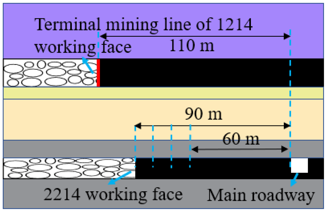
4.1.2. 1214 Working Face Mining

A 70 m boundary was set at the left side of the model for excavation. The model was excavated step-by-step and calculated separately to achieve balance. This section contains only key pictures because it focuses on the values of the stress arch height and span. The stress arch height is the distance from the No. 1 coal seam roof to the inner boundary of the arch crown.
Figure 10 shows that when the 1214 working face was mined to a depth of 150 m, the stress arch height was elongated to 105 m but was not fully formed; for a mining depth of 160 m, the stress arch height was fully developed to 105 m; for mining depths of 180 m and 210 m, the stress arch height remained unchanged and only extended along the strike; for a mining depth of 160 m, the strike fully subsided. Using Equations (7) and (12), we obtained the arch height and span of approximately 105 m and 175 m, respectively.

4.1.3. 2214 Working Face Mining

As the strike of the 1214 working face fully subsided when it was mined to a depth of 160 m, the mining proceeded to the 2214 working face. A 50 m boundary was set on the left side of the model for excavation. The model was excavated step-by-step and calculated separately to achieve balance. The stress arch height is the distance from the No. 2 coal seam roof to the inner boundary of the arch crown.
Figure 11 shows that with repeated mining, the crown of the stress arch formed during the mining of the 1214 working face extended to the higher strata. When the 2214 working face was mined to a depth of 140 m, the stress arch height was elongated to 145 m but not fully formed; for a depth of 200 m, the original stress arch disappeared, and the stress arch height was elongated to 150 m; for a mining depth of 220 m, the stress arch height was stable and elongated to 165 m. The stress arch height and span were 165 m and 235 m, respectively, after repeated mining.

4.2. Evolution of Shape Parameters of Stress Arch by Physical Simulation Similarity Test

4.2.1. Physical Similarity Model

The physical similarity simulation test can intuitively demonstrate the evolution of the overlying strata structure in working face mining [47]. This section describes the use of this method to determine the evolution behavior of the stress arch in close-distance coal seams with repeated mining.
The size of the physical similarity model was 1800 mm × 160 mm × 1400 mm, and the material proportion was determined according to the actual geological parameters. The geometric similarity ratio of this test was 1:200, with 1 cm in the model representing 2 m in practice. We applied a load of 6.84 kN on the top of the model to simulate the unpaved overburden. After the model was laid, we set the displacement measuring points with a row spacing of 10 cm, as indicated by the white dots in Figure 12. The model was excavated 5 cm each time and excavated again after the model was stable.
The inner boundary of the stress arch was composed of the peripheral fractures of the rock stratum. Therefore, the fracture field during the model excavation was captured in real time by a high-speed camera to examine the evolution of the stress arch shape.

4.2.2. 1214 Working Face Mining

A 25 cm boundary was set on the left side of the model, and the 1214 working face was excavated to the right side of the model. Owing to limited space, only the key pictures are included in this section.
Figure 12 shows that when the 1214 working face was mined to a depth of 160 m, the stress arch height was elongated to 80 m; for a depth of 180 m, the elongation was 105 m; for a depth of 220 m, the arch height remained unchanged and only extended along the strike. The stress arch height and span were 105 m and 180 m, respectively.

4.2.3. 2214 Working Face Mining

When the 1214 working face was mined to a depth of 220 m, the mining proceeded to the 2214 working face. A 15 cm boundary was set on the left side of the model, and the 2214 working face was excavated to the right side of the model.
Figure 13 shows that when the 2214 working face was mined to a depth of 150 m, the original stress arch disappeared, and the stress arch height was elongated to 140 m; for a depth of 200 m, the stress arch height was elongated to 165 m; for a depth of 230 m, the stress arch height remained unchanged. When the 2214 working face was repeatedly mined, stress arch height and span were 165 m and 240 m, respectively.

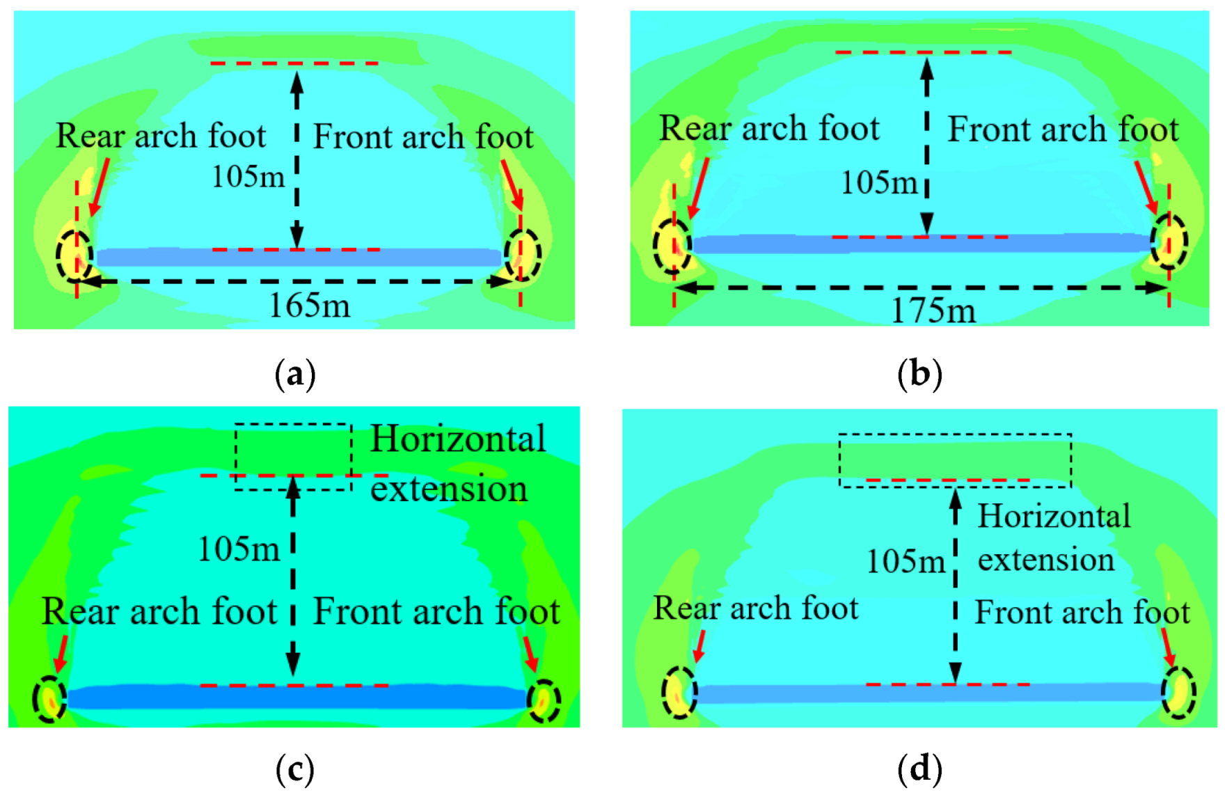
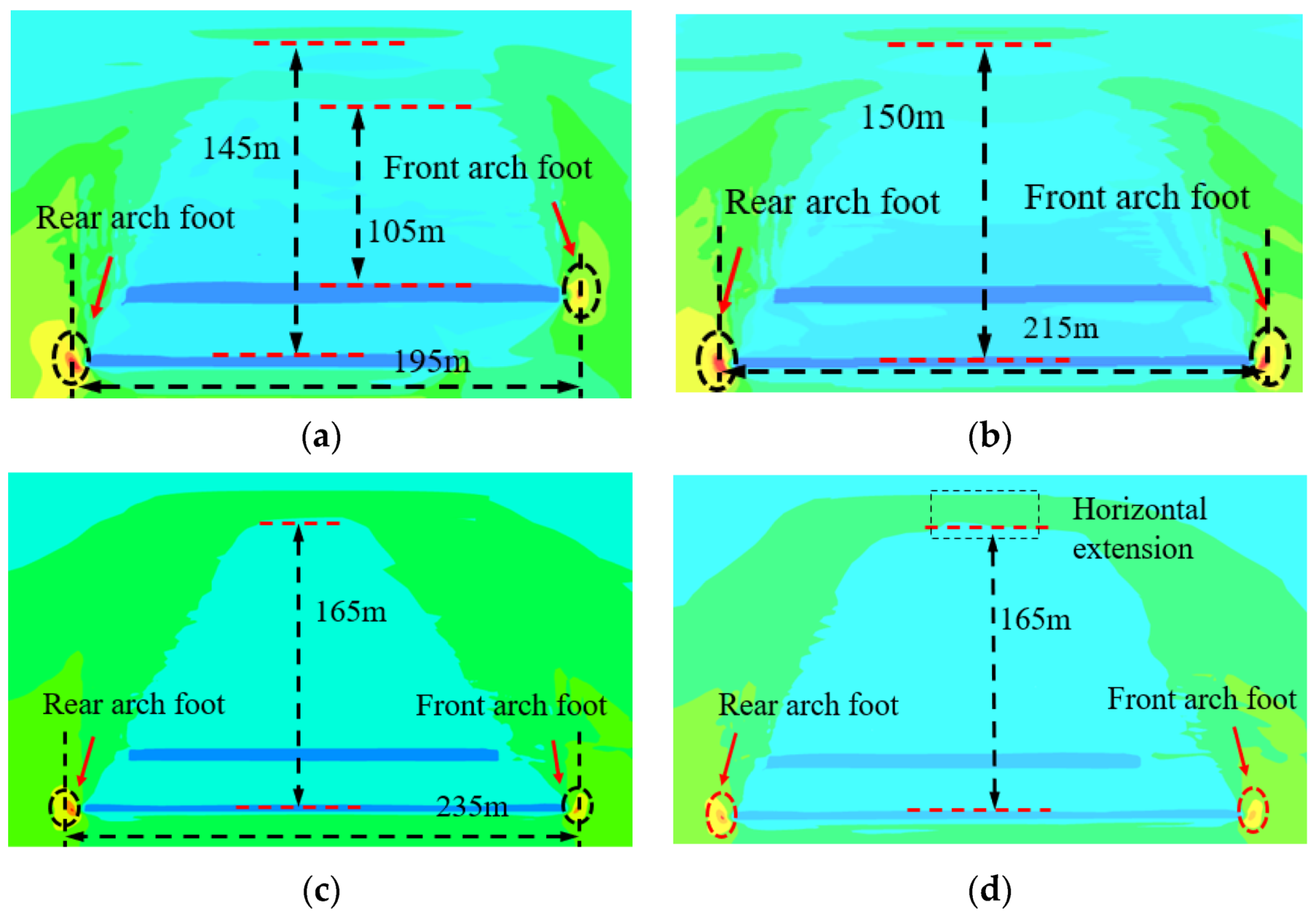
4.3. Determination of Stress Arch Shape Parameters

Table 4 presents the shape parameters of the stress arch obtained in Section 4.1 and Section 4.2. The actual rock stratum histogram was used to determine the stress arch height before and after repeated mining. The arch crowns before and after repeated mining were located at 10 m and 12 m thick fine sandstone, respectively, which are both key strata, verifying the rationality of the values. According to the comprehensive analysis results, the stress arch height and span before and after repeated mining were obtained, as presented in Table 4.

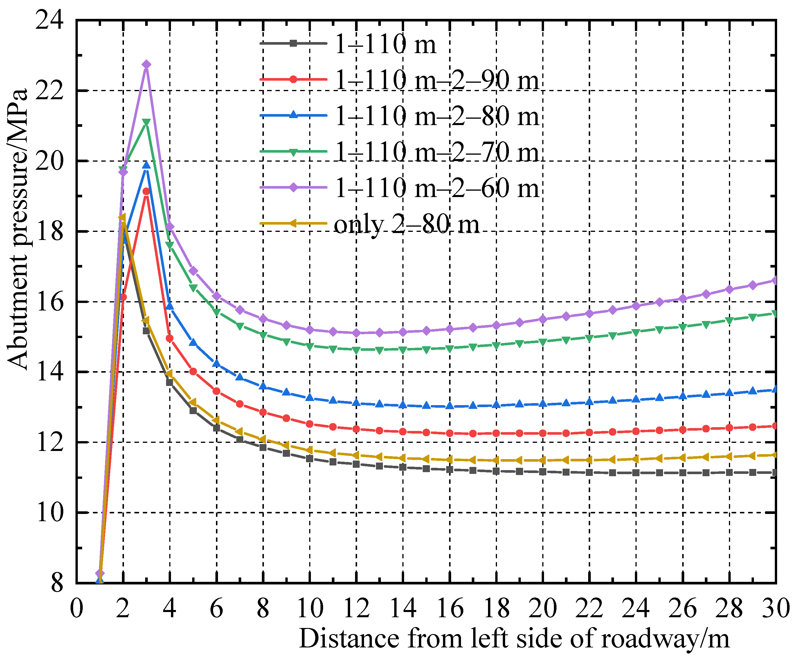
4.4. Determination of Influence Range of Abutment Pressure in Repeated Mining

Substitute K, h, L and H into Equations (11) and (12) to obtain the influence range of the front abutment pressure, as shown in Table 5.
Table 5 shows that when only the 1214 working face was mined, the influence range of the front abutment pressure was 69 m. With repeated mining, the stress arch height and span reached 165 m and 235 m, respectively, resulting in an increase in the influence range of the front abutment pressure to 83.5 m. Therefore, the determination of the width of the stopping coal pillar in close-distance coal seams is significantly different from that in a single coal seam. With repeated mining, the influence range of abutment pressure of the working face will increase significantly.

5. Numerical Analysis of Surrounding Rock Stress of the Main Roadway and Discussion

5.1. Numerical Analysis

Based on the stress arch theory, the pervious section mastered the evolution law of abutment pressure with repeated mining by means of theory, numerical analysis and physical similarity test, and the result is the same as the field measurement. In this section, the FLAC3D numerical simulation software is used to analyze the distribution of the side abutment pressure of the main roadway with the mining of the 2214 working face, providing a further basis for determining the width of the stopping coal pillar. The same numerical simulation model described in Section 4.1.1 was used here.
First, a 50 m boundary was first set on the right side of the model for the main roadway excavation, and the balance was calculated. The boundary coal pillar set for the excavation of the working face was the same as that in Section 4.1.2 and Section 4.1.3. The mining plan of the working face is: (1) according to the actual mining situation, the 1214 working face was mined, and the width of the stopping coal pillar is 110 m, which is calculated to be balanced; then the 2214 working face was mined, and the width of the stopping coal pillars were, respectively 90 m, 80 m, 70 m and 60 m, and the balance was calculated; (2) only the 2214 working face was mined, and the width of stopping coal pillar is 80 m, and the balance was calculated. The working faces mining diagram is shown in the Figure 14. For ease of reading, the width of stopping coal pillar in the 1214 working face is 110 m, and the width of stopping coal pillar in the 2214 working face is 90 m, referred to as 1–110 m–2–90 m, and so on.
The abutment pressure value is extracted from the left side of the main roadway to the working face every 1 m along the horizontal direction, as shown in the Figure 15.
According to the analysis in Figure 15: The side abutment pressure of the main roadway of 2–80 m is basically equal to that 1–110 m. At this time, the mining stress has little effect on the main roadway. The side abutment pressure of the main roadway of 1–110 m–2–80 m is close to 20 MPa. It shows that the influence range of the front abutment pressure of the working face is increased due to repeated mining, so the main roadway is in the influence range of the advance abutment pressure of the working face, so the main roadway is affected by mining stress. According to the numerical simulation results, if it is necessary to ensure that the main roadway is less affected by the mining stress, the width of the stopping coal pillar in the 2214 working face should be greater than 80 m. The conclusions in this section are basically the same as the theoretical analysis and field measurement results.

5.2. Discussion

This paper studies the evolution law of abutment pressure of a working face after repeated mining of close-distance coal seams, which provides a scientific basis for determining the reasonable width of a stopping coal pillar. During the research, we solved the analytical equation of the influence range of the front abutment pressure and analyzed the key factors affecting the front abutment pressure. Subsequently, the stress arch span and height evolution in repeated mining were mastered. Finally, the evolution of the influence range of front abutment pressure at the working face in repeated mining of close-distance coal seams was clarified.
Z. Zhu focuses on the shape of the stress arch along the working face in single seams [32], while this paper focuses on the shape of the stress arch along the working face in close-distance coal seams. L. Wang focuses on the shape of the three-dimensional stress shell of the working face, the stress of the bottom plate and the distribution of the side abutment pressure of the working face [23], while in this paper, the change of the shape of the stress arch is combined with the front abutment pressure of the working face. The methods and conclusions used in this paper are innovative.
With the shortening of the width of the stopping coal pillar, the mining stress disturbance on the main roadway gradually increases, and the stability of the surrounding rock will be intuitively represented by the plastic zone. The cloud map of the plastic zone of surrounding rock of the main roadway in Section 5.1 is extracted, as shown in Figure 16.
According to the analysis in Figure 16: The mining action causes the deflection of the principal stress, and the area of the plastic zone at the diagonal position of the roadway is significantly increased, but the depth of the plastic zone at the roof, floor and both sides of the roadway is basically unchanged. It shows that the stability of the surrounding rock of the roadway has not decreased significantly. Therefore, the width of stopping coal pillar in nonhigh-ground-stress working face can be appropriately shortened. Next, based on the research results of this paper and combined with roadway support technology [48,49], we will study the feasibility of shortening the width of the stopping coal pillar and vigorously improve the coal resource recovery rate in the stopping mining stage of the working face.

6. Conclusions

(1) This study mastered the relationship between the stress arch and the supporting pressure of the working face. The front foot arch of the stress arch is located in the elastic pressurization zone. We derived a rational equation for the stress arch under a nonlinear load. We also solved the analytical equation of the influence range of the front abutment pressure. The stress arch height and span are negatively and positively correlated with the influence range of the front abutment pressure, respectively.
(2) The change of stress arch shape parameters with repeated mining is studied through numerical simulation analysis and physical simulation similarity test. After the 1214 working face was mined and its strike fully subsided, the stress arch height and span were 105 m and 175 m, respectively. After the repeated mining of the 2214 working face, the stress arch height and span increased to 165 m and 235 m, respectively.
(3) Through mastering the change of stress arch shape, the evolution law of abutment pressure of the working face was clarified. With repeated mining, the influence range of the front abutment pressure of the working face where the front arch foot is located increased from 69 m to 83.5 m. The law obtained is consistent with the field measurement. If it is necessary to ensure that the main roadway is less affected by the mining stress, the width of the stopping coal pillar in the 2214 working face should be greater than 80 m.

Author Contributions

Conceptualization, F.H. and L.L.; methodology, K.L.; software, X.X.; investigation, B.Q.; data curation, B.Q.; writing—original draft preparation, L.L.; writing—review and editing, Q.M. and Y.C.; funding acquisition F.H. and L.L. All authors have read and agreed to the published version of the manuscript.

Funding

This work was supported by the National Natural Science Foundation of China (No.51974317), the Fundamental Research Funds for the Central Universities (2022YJSNY09) and the China Scholarship Council (No.202106430048, 202106430055).

Institutional Review Board Statement

Not applicable.

Informed Consent Statement

Informed consent was obtained from all subjects involved in the study.

Data Availability Statement

The data presented in this study are available on request from the corresponding author. The data are not publicly available due to restrictions of privacy.

Acknowledgments

The writers acknowledge the editor, reviewers and funding agencies.

Conflicts of Interest

The authors declare that there are no conflict of interest.

References

  1. Nezhad, M.M.; Fisher, Q.J.; Gironacci, E.; Rezania, M. Experimental Study and Numerical Modeling of Fracture Propagation in Shale Rocks During Brazilian Disk Test. Rock Mech. Rock Eng. 2018, 51, 1755–1775. [Google Scholar] [CrossRef]
  2. Wang, F.; Wang, M.; Zhu, Z.M.; Deng, J.H.; Nezhad, M.M.; Qiu, H.; Ying, P. Rock Dynamic Crack Propagation Behaviour and Determination Method with Improved Single Cleavage Semi-circle Specimen Under Impact Loads. Acta Mech. Solida Sin. 2020, 33, 793–811. [Google Scholar] [CrossRef]
  3. Wang, M.; Zhu, Z.M.; Dong, Y.Q.; Zhou, L. Study of mixed-mode I/II fractures using single cleavage semicircle compression specimens under impacting loads. Eng. Fract. Mech. 2017, 177, 33–44. [Google Scholar] [CrossRef]
  4. Yang, R.S.; Xu, P.; Yue, Z.W.; Chen, C. Dynamic fracture analysis of crack-defect interaction for mode I running crack using digital dynamic caustics method. Eng. Fract. Mech. 2016, 161, 63–75. [Google Scholar] [CrossRef]
  5. Gao, C.; Huang, D.; Chang, X.; Xi, H. Risk Analysis and Extension Assessment for the Stability of Surrounding Rock in Deep Coal Roadway. Int. J. Environ. Res. Public Health 2019, 16, 4752. [Google Scholar] [CrossRef] [PubMed]
  6. Luo, Y.; Xu, K.; Huang, J.; Li, X.; Liu, T.; Qu, D.; Chen, P. Impact analysis of pressure-relief blasting on roadway stability in a deep mining area under high stress. Tunn. Undergr. Space Technol. 2021, 110, 103781. [Google Scholar] [CrossRef]
  7. Zhao, C.; Li, Y.; Liu, G.; Meng, X. Mechanism analysis and control technology of surrounding rock failure in deep soft rock roadway. Eng. Fail. Anal. 2020, 115, 104611. [Google Scholar] [CrossRef]
  8. Wang, H.; Jiang, C.; Zheng, P.; Li, N.; Zhan, Y. Deformation and failure mechanism of surrounding rocks in crossed-roadway and its support strategy. Eng. Fail. Anal. 2020, 116, 104743. [Google Scholar] [CrossRef]
  9. Hao, J.; Li, X.; Song, Y.; Zhang, P.; Liu, H. Analysis of mining roadway with large deformation of broken soft coal and research on supporting technology: A case study in Xin’an coal mine, China. Eng. Fail. Anal. 2021, 130, 105761. [Google Scholar] [CrossRef]
  10. Guangchao, Z.; Chuanwei, Z.; Miao, C.; Guangzhe, T.; You, L.; Weihua, H.; Hongzhou, W.; Deshuai, Z. Ground response of entries driven adjacent to a retreating longwall panel. Int. J. Rock Mech. Min. 2021, 138, 104630. [Google Scholar] [CrossRef]
  11. Ma, Q.; Tan, Y.; Liu, X.; Gu, Q.; Li, X. Effect of coal thicknesses on energy evolution characteristics of roof rock-coal-floor rock sandwich composite structure and its damage constitutive model. Compos. Part B Eng. 2020, 198, 108086. [Google Scholar] [CrossRef]
  12. Qian, M.; Xu, J. Behaviors of strata movement in coal mining. J. China Coal Soc. 2019, 44, 973–984. [Google Scholar]
  13. Song, Z.; Lu, G.; Xia, H. A new algorithm for calculating the distribution of face abutment pressure. J. Shandong Univ. Sci. Technol. (Nat. Sci.) 2006, 1–4. Available online: https://kns.cnki.net/kcms/detail/detail.aspx?dbcode=CJFD&dbname=CJFD2006&filename=SDKY200601000&uniplatform=NZKPT&v=Pl9e6V5jitLh4DaH0FNrxzWKxL-MTx5bv9ohI_if1BdGFnPtcJLikaaS1vmZUZeA (accessed on 25 July 2022). [CrossRef]
  14. Zhu, S.; Feng, Y.; Jiang, F. Determination of Abutment Pressure in Coal Mines with Extremely Thick Alluvium Stratum: A Typical Kind of Rockburst Mines in China. Rock Mech. Rock Eng. 2016, 49, 1943–1952. [Google Scholar] [CrossRef]
  15. Ji, Y.G.; Wang, X.J.; Zhou, Y.P.; Zhang, X.T. Study on the Distribution Law of Front Abutment Pressure of Long Fully-Mechanized Working Face in Deep Mine. In Proceedings of the 8th Russian-Chinese Symposium Coal in the 21st Century: Mining, Processing, Safety, Kemerovo, Russia, 10–12 October 2016; Tailakov, O.V., Ed.; Atlantis Press: Zhengzhou, China, 2016; Volume 92, pp. 159–162. [Google Scholar]
  16. Xie, J.; Xu, J. Effect of key stratum on the mining abutment pressure of a coal seam. Geosci. J. 2017, 21, 267–276. [Google Scholar] [CrossRef]
  17. Li, Y.; Lei, M.; Wang, H.; Li, C.; Li, W.; Tao, Y.; Wang, J. Abutment pressure distribution for longwall face mining through abandoned roadways. Int. J. Min. Sci. Technol. 2019, 29, 59–64. [Google Scholar] [CrossRef]
  18. Li, A.; Ma, Q.; Ma, L.; Kang, L.; Mu, Q.; Chen, J. Coal Mine Abutment Pressure Distribution Based on a Strain-Softening Model. Front. Phys. 2020, 8, 263. [Google Scholar] [CrossRef]
  19. Zhang, P.; Sun, B. Distribution characteristics of the advance abutment pressure in a deep stope. J. Geophys. Eng. 2020, 17, 686–699. [Google Scholar] [CrossRef]
  20. Liu, J.; Jiang, F.; Zhu, S. Study of dynamic and static abutment pressure around longwall face and its application. Chin. J. Rock Mech. Eng. 2015, 34, 1815–1827. [Google Scholar]
  21. Xue, D.; Zhou, H.; Peng, R.; Wang, J.; Deng, L.; Zhao, Y. Strong disturbance of discontinuous abutment pressure. Chin. J. Rock Mech. Eng. 2018, 37, 1080–1095. [Google Scholar]
  22. Han, H.; Xu, J.; Wang, X.; Xie, J.; Xing, Y. Method to Calculate Working Surface Abutment Pressure Based on Key Strata Theory. Adv. Civ. Eng. 2019, 2019, 7678327. [Google Scholar] [CrossRef]
  23. Wang, L.; Xie, G.; Wang, J. Numerical investigation on the influence of surrounding rock stress hell on fractured field. J. China Coal Soc. 2015, 40, 2009–2014. [Google Scholar]
  24. Wang, F.; Chen, T.; Ma, B.; Chen, D. Formation mechanism of stress arch during longwall mining based on key strata theory. Energy Explor. Exploit. 2022, 40, 816–833. [Google Scholar] [CrossRef]
  25. Wang, S.R.; Wu, X.G.; Zhao, Y.H.; Hagan, P.; Cao, C. Evolution Characteristics of Composite Pressure-Arch in Thin Bedrock of Overlying Strata During Shallow Coal Mining. Int. J. Appl. Mech. 2019, 11, 1950030. [Google Scholar] [CrossRef]
  26. Xia, B.; Zhang, X.; Yu, B.; Jia, J. Weakening effects of hydraulic fracture in hard roof under the influence of stress arch. Int. J. Min. Sci. Technol. 2018, 28, 951–958. [Google Scholar] [CrossRef]
  27. Wang, S.; Wu, X.; Zhao, Y.; Hagan, P. Mechanical Performances of Pressure Arch in Thick Bedrock during Shallow Coal Mining. Geofluids 2018, 2018, 2419659. [Google Scholar] [CrossRef]
  28. Zhao, Y.; Wang, S.; Hagan, P.; Ren, L.; Zou, Z. Pressure-Arching Characteristics in Roof Blocks during Shallow Coal Mining. Adv. Civ. Eng. 2018, 2018, 6817059. [Google Scholar] [CrossRef]
  29. Jin, C.; Shao, A.; Liu, D.; Han, T.; Fan, F.; Li, S. Failure Mechanism of Highly Stressed Rock Mass during Unloading Based on the Stress Arch Theory. Int. J. Geomech. 2018, 18, 04018146. [Google Scholar] [CrossRef]
  30. Yang, D.; Guo, W.; Yu, Q.; Tan, Y.; Deng, W. Structural characteristics and evolution mechanism of overlying strata pressure arch in shallow and flat seams. J. Min. Saf. Eng. 2019, 36, 323–330. [Google Scholar]
  31. Zhao, Y.; Yu, J.; Zhou, C.; Zhao, K.; Xiao, H. Characterization of pressure arching effect of arch shell surrounding rock considering deviation of principal stress axis. Chin. J. Geotech. Eng. 2021, 43, 1842–1850. [Google Scholar]
  32. Zhu, Z. Structure Characteristics and Control Technology of Surrounding Rocks in Non-Pillar Mining by Roof Cutting. Ph.D. Thesis, China University of Mining and Technology, Beijing, China, 2019. [Google Scholar]
  33. Pang, R.; Xu, B.; Zhou, Y.; Song, L.F. Seismic time-history response and system reliability analysis of slopes considering uncertainty of multi-parameters and earthquake excitations. Comput. Geotech. 2021, 136, 104245. [Google Scholar] [CrossRef]
  34. Pang, R.; Xu, B.; Zhou, Y.; Zhang, X.; Wang, X.L. Fragility analysis of high CFRDs subjected to mainshock-aftershock sequences based on plastic failure. Eng. Struct. 2020, 206, 110152. [Google Scholar] [CrossRef]
  35. Qian, M. Ground Pressure and Strata Control; China University of Mining and Technology Press: Xuzhou, China, 2010. [Google Scholar]
  36. Li, L.; Shang, C.; Chu, K.; Zhou, Z.; Song, S.; Liu, Z.; Chen, Y. Large-scale geo-mechanical model tests for stability assessment of super-large cross-section tunnel. Tunn. Undergr. Space Technol. 2021, 109, 103756. [Google Scholar] [CrossRef]
  37. Wen, Z.; Jing, S.; Jiang, Y.; Tian, L.; Wen, J.; Cao, Z.; Shi, S.; Zuo, Y. Study of the Fracture Law of Overlying Strata under Water Based on the Flow-Stress-Damage Model. Geofluids 2019, 2019, 3161852. [Google Scholar] [CrossRef]
  38. Wang, Z.; Guo, L.; Su, Z.; Wang, J.; Xu, J. Application of visible post-processing method of FLAC3D model node displacement in surface subsidence. J. Min. Sci. Technol. 2016, 1, 249–255. [Google Scholar]
  39. Wang, S.; Liu, Y.; Yang, Q.; Wang, X. Analysis of the Abutment Movements of High Arch Dams due to Reservoir Impoundment. Rock Mech. Rock Eng. 2020, 53, 2313–2326. [Google Scholar] [CrossRef]
  40. Zhao, Y.; Wang, T.; Jiang, Y.; Pan, L.; Zhang, K. Application of Hoek-Brown criterion in numerical simulation of ground pressure features in multi-seam longwall mining. J. China Coal Soc. 2013, 38, 970–976. [Google Scholar]
  41. Wang, H.; Poulsen, B.A.; Shen, B.; Xue, S.; Jiang, Y. The influence of roadway backfill on the coal pillar strength by numericalinvestigation. Int. J. Rock Mech. Min. 2011, 48, 443–450. [Google Scholar] [CrossRef]
  42. Mohammad, N.; Reddish, D.J.; Stace, L.R. The relation between in situ and laboratory rock properties used in numerical modelling. Int. J. Rock Mech. Min. 1997, 34, 289–297. [Google Scholar] [CrossRef]
  43. Cai, M.; He, M. Rock Mechanics and Engineering; Science Press: Beijing, China, 2013. [Google Scholar]
  44. Wang, S.L.; Hao, S.P.; Chen, Y.; Bai, J.B.; Wang, X.Y.; Xu, Y. Numerical investigation of coal pillar failure under simultaneous static and dynamic loading. Int. J. Rock Mech. Min. 2016, 84, 59–68. [Google Scholar] [CrossRef]
  45. Shabanimashcool, M.; Li, C.C. A numerical study of stress changes in barrier pillars and a border area in a longwall coal mine. Int. J. Coal Geol. 2013, 106, 39–47. [Google Scholar] [CrossRef]
  46. Zhang, Z.Z.; Bai, J.B.; Chen, Y.; Yan, S. An innovative approach for gob-side entry retaining in highly gassy fully-mechanized longwall top-coal caving. Int. J. Rock Mech. Min. 2015, 80, 1–11. [Google Scholar] [CrossRef]
  47. Wang, C.X.; Shen, B.T.; Chen, J.T.; Tong, W.X.; Jiang, Z.; Liu, Y.; Li, Y.Y. Compression characteristics of filling gangue and simulation of mining with gangue backfilling: An experimental investigation. Geomech. Eng. 2020, 20, 485–495. [Google Scholar]
  48. Chen, J.H.; Liu, P.; Liu, L.; Zeng, B.Q.; Zhao, H.B.; Zhang, C.; Zhang, J.W.; Li, D.Q. Anchorage performance of a modified cable anchor subjected to different joint opening conditions. Constr. Build. Mater. 2022, 336, 127558. [Google Scholar] [CrossRef]
  49. Chen, J.H.; Zeng, B.Q.; Liu, L.; Tao, K.M.; Zhao, H.B.; Zhang, C.; Zhang, J.W.; Li, D.Q. Investigating the anchorage performance of full-grouted anchor bolts with a modified numerical simulation method. Eng. Fail. Anal. 2022, 141, 106640. [Google Scholar] [CrossRef]
Figure 1. Plane layout of working faces.
Sustainability 14 12399 g001
Figure 2. Rock stratum histogram.
Sustainability 14 12399 g002
Figure 3. Ground pressure appearance of the surrounding rock of the main roadway.
Sustainability 14 12399 g003
Figure 4. Layout of borehole stressmeters: (a) Layout of 1206 working face, (b) Layout of 2216 working face.
Sustainability 14 12399 g004
Figure 5. Borehole stressmeters monitoring data: (a) Date of 1216 working face, (b) Date of 2216 working face.
Sustainability 14 12399 g005
Figure 6. Shape of stress arch of close-distance coal seam, (a) Type 1, (b) Type 2, (c) Type 3.
Sustainability 14 12399 g006
Figure 7. The front arch foot of stress arch.
Sustainability 14 12399 g007
Figure 8. Mechanical model for stress arch under nonlinear load.
Sustainability 14 12399 g008
Figure 9. Relationship between elastic pressurization zone and two variables.
Sustainability 14 12399 g009
Figure 10. Evolution law of stress arch with mining: (a) 150 m mined on the 1214 working face, (b) 160 m mined on the 1214 working face, (c) 180 m mined on the 1214 working face, (d) 210 m mined on the 1214 working face.
Sustainability 14 12399 g010
Figure 11. Evolution law of stress arch in repeated mining: (a) 140 m mined on the 2214 working face, (b) 200 m mined on the 2214 working face, (c) 220 m mined on the 2214 working face (d) 240 m mined on the 2214 working face.
Sustainability 14 12399 g011
Figure 12. Evolution law of stress arch with mining: (a) 160 m mined on the 1214 working face, (b) 180 m mined on the 1214 working face, (c) 220 m mined on the 1214 working face.
Sustainability 14 12399 g012
Figure 13. Evolution law of stress arch in repeated mining: (a) 150 m mined on the 2214 working face, (b) 200 m mined on the 2214 working face, (c) 230 m mined on the 2214 working face.
Sustainability 14 12399 g013
Figure 14. Working faces mining diagram.
Sustainability 14 12399 g014
Figure 15. Side abutment pressure of main roadway.
Sustainability 14 12399 g015
Figure 16. Cloud map of plastic zone: (a) 1–110 m–2–90 m, (b) 1–110 m–2–80 m, (c) 1–110 m–2–70 m, (d) 1–110 m–2–60 m.
Sustainability 14 12399 g016
Table 1. Mechanical parameters of coal and rock mass in calculation model.
LayerNatural DensityShear ModulusBulk ModulusCohesionInternal Friction AngleTensile Strength
kg/m3/GPa/GPa/MPa/(°)/MPa
Overlying strata25007.809.003.40321.53
Coarse sandstone25808.4011.234.10361.55
Fine sandstone26128.2411.794.23311.55
Siltstone23004.265.792.23311.20
No. 1 coal seam15503.364.511.00270.08
Fine sandstone26128.2411.794.23311.50
Medium-fine sandstone25807.909.302.40321.30
Kaolinite rock24506.898.762.30301.30
Conglomerate25207.549.232.90311.40
Carbonaceous mudstone23604.355.871.80291.20
No. 2 coal seam15503.364.511.00270.08
Carbonaceous mudstone23604.355.871.80291.20
Kaolinite rock24506.898.762.30301.30
Medium-fine sandstone25807.909.302.40321.30
Table 2. Cap pressures.
Strain0.000.010.030.050.070.090.110.130.150.17
Stress (MPa)0.000.531.783.375.448.2612.3418.7630.3057.23
Table 3. Materials parameters for double-yield model.
ParameterNatural Density kg/m3Shear Modulus/GPaBulk Modulus/GPaFriction Angle/°Dilatancy Angle/°
Value11001.153.74208
Table 4. Shape parameters of stress arch.
Mining StageBefore Repeated MiningAfter Repeated Mining
Shape Parametersh/mL/mh/mL/m
Numerical simulation105175165235
Physical similarity simulation105180165240
Final value105175165235
Table 5. Influence range of front abutment pressure.
Working Face MiningH/mh/mL/mKLC/m
Only 1214400105175469
1214, 2214425165235483.5
Publisher’s Note: MDPI stays neutral with regard to jurisdictional claims in published maps and institutional affiliations.

