Article

Structural Analysis of an In-Wheel Motor with Integrated Magnetic Gear Designed for Automotive Applications

by
Claudia Violeta Pop
,
Daniel Fodorean
and
Dan-Cristian Popa
*
Department of Electrical Machines and Drives, Technical University of Cluj-Napoca, 400114 Cluj-Napoca, Romania
*
Author to whom correspondence should be addressed.
Sustainability 2022, 14(19), 12007; https://doi.org/10.3390/su141912007
Submission received: 12 August 2022 / Revised: 18 September 2022 / Accepted: 20 September 2022 / Published: 22 September 2022
(This article belongs to the Section Sustainable Transportation)

Abstract

:
This paper is focused on the structural analysis of a new propulsion system defined by an in-wheel motor with an integrated magnetic gear (IWM-IMG). The IWM-IMG has two levels of torque and speed. First, the state of the art of magnetic gears (MGs) is presented. Next, the proposed structure and the main designing steps are depicted. The advantages of the proposed structure are emphasized, in terms of speed increase operation, knowing that this is achieved without it being necessary to increase the fed frequency via the inverter. Moreover, the electromagnetic characteristics are briefly introduced to prove the suitability of the proposed solution for the considered application. Next, the structural analysis is detailed, where through an analytical, numerical and experimental approach, the study is validated.

1. Introduction

The concerned application in our study is the electric vehicle (EV). EVs are complex systems, and their study implies the use of different strategies and methods in an interdisciplinary approach [1,2]. In general, for EVs, higher speed and increased autonomy are strongly related to the weight of the propulsion unit [3,4,5,6]. To transfer the torque speed from the electric motor to the traction wheel, a gear is generally used. A high transmission ratio from the gear can be hardly obtained when using just one gear. A solution to obtain the desired transmission ratio is to use multiple linked gears [6]. Hence, the propulsion unit will be affected by the increased weight and volume, with consequences on the power density and efficiency of the overall system. To overcome this issue, a solution can be the replacement of the mechanical gear with a magnetic one. Multiple advantages to the drive chain can be achieved with this variant, emphasized later.
A classical mechanical gear is a unit which transfers torque or speed from one shaft to another through mechanical teeth contact [7,8]. Thus, some important drawbacks occur. First, local friction and heat are produced at the teeth level, leading to losses. The physical contact between the teeth will also lead to the stress of the tooth flanges. Due to the long operation time, material friction and fatigue lead to the irreversible damage of the teeth. Moreover, because of the material friction, the metallic parts must be lubricated often, due to continuously varying temperatures at the teeth level.
All these drawbacks are eliminated in the case of magnetic gears (MGs) because the metallic teeth are replaced with magnets. The transition from a mechanical gear to a magnetic one is shown in Figure 1. There is no physical contact between the magnetic pole pieces of an MG. Hence, there is no heating, no need for lubrication and no material damage. The losses found in the active parts are represented by the iron loss component, and the mechanical one is due to bearing friction. Moreover, the levels of noise and vibration are decreased in the case of MGs.
At the beginning of the 20th century, the idea of magnetic gear emerged, and it was patented in 1901 [9]. The original topology was described as an electromagnetic gear, which unfortunately did not pique interest at that time due to its poor efficiency. Later, in 1941 [10], another topology of MGs was proposed, but still, the interest in it and its use remained low at that time. The poor performance of the magnetic materials made the idea of widely employing magnetic gears in industry almost impossible. Later, in the 1980s, ferrite magnetic material wa.s replaced by neodymium iron boron (NdFeB) material, which exhibits better performance (i.e., power density), and this change accelerated the research interest in MGs [11,12,13,14,15,16].
For the MG shown in Figure 1, the transition from a mechanical to a magnetic gear was made by simply replacing the iron core teeth with permanent magnets (PMs) with alternating polarity. The shortcoming of this topology is the low-level utilization of PMs, because only a part of magnetic poles was in active magnetic contact, which gave an efficiency of 20–30%. The first efficient MG solution that fully exploits all the gear magnets dates to early 2000. This variant was proposed by Atallah and Howe [17] and it was a coaxial MG. The operation principle was based on modulation of the magnetic fields produced by two rotors, with PM pole pieces. Based on the idea of field modulation, numerous similar configurations with fixed transmission ratios have been proposed. The number of magnetic poles used for an MG is critical as it has a direct influence in the transmission ratio and affects the mechanical performances (i.e., the torque ripples).
Various types of MG architectures have been studied with different efficiency levels. One of them is the planetary type. Some scientific papers present the various applications for this topology [18,19,20,21,22,23,24], most of them being related to wind power [23,24]. The main advantages of this topology are the high speed ratio and the possibility of three terminals for input or output speed torque.
The second studied topology is the harmonic MG. The operating principle is based on the high-speed rotor moving around and creating “gear teeth” on the low-speed rotor. The high-speed rotor or the inner rotor presses on the low-speed rotor, which is “flexible”. Since in this specific case, the low-speed rotor has two fewer teeth than the stator, each revolution causes a displacement of the output with two teeth. This movement produces a time-varying sinusoidal variation of the airgap [25,26]. The main advantage of such a model is the high torque density. Additionally, a high gear ratio can be achieved. On the other hand, although it has significant functionality, this topology needs a flexible magnetic rotor, which is quite complex, constituting the main drawback of the structure. Such MG topology is suitable for applications that require positional accuracies, such as robotics or medical tools.
Another type is the axial MG topology, studied by Mezani [27]. This structure comprises two rotors, for low and high speed, covered on the inner face with PMs. The ferromagnetic pole pieces axially arranged are placed between the PMs, having the power transferring role [28,29,30,31,32]. Specifically, in [32], an MG with a 30:1 gear ratio was investigated. However, the performances of the axial topology were not extensively studied, since a relatively small number of papers presented their real physical integration. Due to their good power density, the axial MGs should be suitable in food and aeronautic industries.
Next, a linear topology was studied in [33,34,35], having three main parts: the inner rotor, with PMs on the axial surface; the stator, composed of the modulating segments; and the outer rotor, with PMs mounted on the inner face. Very high force density can be reached by using such topology. On the other hand, a drawback is the sensitivity at the axial length of the space between the rings placed between the PMs of the rotors [35,36,37]. The advantages of using linear gears make them suitable for applications such as wave power generation, or other types of renewable energy [38,39,40,41].
Based on the above information, one can conclude that the radial MG shows the best results in terms of torque density. The key benefit of this configuration is the contribution of all PMs, simultaneously, in the torque transmission. The torque density of these MGs is comparable with that of the mechanical ones [42], and we considered such a variant for our proposition of a new propulsion system with an integrated magnetic gear.
Thus, our goal is to propose a two-transmission-step topology, containing an in-wheel motor with an integrated magnetic gear (IWM-IMG), capable of increasing the speed of the propulsion unit without increasing the fed frequency—and thus obtaining suitable efficiency, even at high speeds, and reducing the mechanical stress on the switching components of the power converters. With this in mind, the analysis presented here is focused on the structural analysis of our IWM-IMG, and the main elements of the design, the characteristics and performances of the propulsion system are presented.

2. The Topology under Study and the Main Steps in the Analytical Design

A.
Structure Under Study, the IWM-IMG
The problem of increasing the speed in electrical machines comes from the fed frequency limit of 400 Hz for industrial applications. We propose a two-step electromagnetic geared with an option to increase speed. An in-wheel motor (IWM) is the first component of our propulsion unit. It means that the rotor is the exterior part, and next, above our rotor, a radial-type magnetic gear is placed, practically attached to the motor. Thus, the inner rotor of the MG is rotating at the same speed as the outer rotor of the IWM. Thus, we obtain an in-wheel motor with integrated magnetic gear (IWM-IMG), and its structure is depicted in Figure 2 (with magnification for a closer look on its configuration).
The stator is the interior part of the IWM. The structure chosen here has a fractional slot winding configuration. Next, one can see the first airgap. Above it, the double structure inner rotor is placed. Two rings made of PMs and steel are mirrored on the sides of one ring of non-conducting material. Next is the static part, with alternating conducting and non-conducting materials. Next is the outer rotor, with one PM layer and the iron yoke.
Our IWM-IMG was designed to develop an output power of 1500 W, operating at a rated speed of 420 r/min. The MG acts like a speed multiplier, so it can achieve 1428 r/min, 3.4 times more than the IWM, for the same fed frequency. This multiplication of the speed is achieved without increasing the iron losses in the machine and without producing supplementary heat and chopping losses within the static converter used to feed the motor. The main parameters of the IWM with an integrated MG are shown in Table 1.
  • B. Characteristics of the Used Materials
Materials of high quality must be used to maximize the power density of the IWM-IMG and to provide high performances for the application. Hence, the PM chosen for the current application is of NdFeB type. This kind of material keeps its operational condition up to 160 °C. The main material specifications are shown in Table 2.
The materials used for manufacturing the MG are the same as for the IWM, having the same properties. Based on the topology of the IWM, the MG was built considering the geometrical constraints for the inner rotor diameter and length of the stack.
  • C. Main Designing Steps
The electromagnetic design process is developed for the structure with the outer rotor and the three-phase winding with fractional slots, to be integrated with the radial MG. The design process starts with the expression of the output power, from which the airgap diameter is derived [42,43,44,45,46]. The other parameters are obtained based on it. For in-wheel applications, the motor’s structure and materials must be carefully chosen to fulfill the performance and cost requirements. Next, the calculation of the geometrical and electromechanical parameters is performed, and the characteristics of the propulsion unit are obtained, as well as the mass and volume of the structure, which directly affect its efficiency [43,46].
The airgap diameter measured at the middle of the distance between the stator and rotor can be calculated starting from the rated power of the IWM, denoted with PN; it is calculated as a function of the induced electromotive force (emf), E, the supplied current I, the estimated efficiency of the machine, η , and the machine’s number of phases, n p h :
P N = η · n p h T · 0 T i ( t ) · e ( t ) d t = η · n p h · k p · E m a x · I m a x
The peak value of the emf can be expressed as:
E m a x = k e · N t · B g a p · D g a p · L m · f s p p
(with the commonly known definition of frequency, as the product of the number of pole pairs, pp, and of the rated speed).
The diameter in the middle of the airgap is determined using the next expression, where all the other parameters are either calculated or imposed:
D g a p = 2 · p p · P N π · A S · k e · k i · k p · k l · η · B g a p · f s 3
where the coefficients k e , k i , k p and k l are emf, current, power and geometrical coefficients, respectively [42]. (The length of the machine is a function of the geometry coefficient kl, based on the known expression: Lm = Dgap ∙ kl.)
Considering a surface PM structure, the airgap flux density can be determined:
B g a p = B r m p · h m p μ r m p g a p + h m p μ r m p
where Brmp is the specific remanent flux density, μ r m p is the magnetic permeability, gap is the airgap length and hpm is the PM’s height.
For the sizing of the machine, other main parameters refer to the number of slots, number of coils per slot, winding turns and the geometry of the slot. For stator sizing, the geometrical aspects of the slots must be clarified.
The number of coils per phase depends on the number of slots and the number of coils per slot. Thus, the number of coils per phase can be calculated as:
N c = Z S 2 · q · p p · 1 N C S
where q is the number of slots per pole and phase, and N c s is the number of coils per slot.
The estimated current on a stator phase can be calculated using:
I p h = P N n p h · U p h · cos φ · η
where cos φ   and   η are the estimated power factor and efficiency, respectively.
The inner rotor contains two layers of magnets, on the inner and outer side of the rotor, separated by a layer of non-magnetic steel. The height of the PM is the same for both layers, 3.5 mm. The polar pitch, which is the length of the arc between two consecutive magnets, is expressed by:
τ p = π · D p m 2 · p p
The flux of the PM for one polar pitch can be determined by using:
Φ p m = τ p · α p m · L m · B g a p
This particularity of MG is based on the use of a ring of alternating pieces of iron and nonconductive material as a static part. On the sides of this ring in the radial direction there are two airgaps, which have the same length as the first airgap. For this part of structure, the sizing is similar to that of the stator.
The input power of the propulsion unit can be calculated by using Equation (9), where Id and Iq are the direct and quadrature current:
P i n = n p h · U p h · ( I q · cos ( δ ) I d · sin ( δ ) )
The output power is expressed as a difference between the input electrical power of the machine and the total losses of the machine:
P o u t = P i n L o s s e s
For the calculation of the mechanical power produced by the MG, the first equation is for produced speed, at its outer rotor:
o u t = i n G r = i n · p i n p o u t
where i n is the inner speed of the MG, G r is the gear ratio, p i n is the pair of poles for the inner rotor of the MG and p o u t is the pair of poles for the outer rotor. The relation between the pair of poles and the number of steel teeth, Ns, is given by:
p o u t = N s p i n
Considering that the main source of flux is that of the inner rotors of the MG, which is produced through the rotation of the outer rotor of the IWM, modulated through the static parts of the MG, the magnetomotive force produced by the outer rotor is:
T M G = Φ M G _ i n · F M G _ o u t
The flux of the inductor of the MG (inner rotor part) is accordingly the product of flux density distribution and the cross-section of the surface on which the flux flows. Attalah elaborated in [17] the frequential model of the flux density by calculating it from the radial component of the field source and the modulating component, due to the static part of the MG. This flux density is given by:
B g a p M G ( θ ) = ( m = 1 , 3 , 5 b r m ( R r ) · cos ( m · p x · ( θ r · t ) + m · p x · θ 0 ) ) × ( j = 1 ,   3 ,   5 λ θ j ( R s ) · cos ( j · N s · ( θ s · t ) ) + λ θ 0 ( R s ) )
where Rr and Rs are the radius of the rotor and of the static part, where the flux density is computed. px refers to the inner or outer rotor number pair of poles. Ωr is the speed of the inner rotor of the MG. b r and λ θ are the Fourier coefficients for the flux density and the modulating flux, respectively. θ is the rotor displacement, and ΩS is the angular speed of the outer rotor (or of the steel teeth part, in the case of a structure for which the teeth part is mobile). Next, the determination of the magnetomotive force is based on the distributed flux and the reluctance of the circuit through which the flux flows, and is given by:
F M G _ o u t = Φ M G _ o u t · M G _ o u t
Moreover, in order to reduce, as much as possible, the torque ripples, which are images of the vibration and noise behavior of electromagnetic transmission, a specific configuration of poles and teeth of the IMG must be found. In fact, the lowest level of torque ripple is reached when the ripple coefficient (kr) equals unity (the ideal case) [7]:
k r = 2 · P i n · N S L C M ( 2 · P i n , N S )
where LCM denotes the least common multiple between the number of poles of the inner rotor and the fixed iron teeth.
Accurate and reliable results in terms of losses are hard to obtain. The computation of losses for the studied structure can be a difficult task, because the complexity of the structure is combined with the phenomena related to different types of losses.
In electrical machines, the losses can be classified into three categories: copper losses, iron losses and mechanical losses. The first category, the copper losses or Joule losses, are dependent on the temperature and the resistance of the copper wire, because these two are related. The mathematical expression used to calculate the coppers losses is:
P c o = n p h · R p h · I p h 2
The second category of losses requires special attention [42]. For determining this category of iron losses, a sum of three subcategories of losses is used: hysteresis loss, eddy current loss and excess loss:
P d _ x = k h y s t · B x 2 · f s + π 2 · σ i r o n · d l a m 2 6 · ( B x · f s ) 2 + k e x c · ( B x · f s ) 3 2   · 8.67
where the subscript x represents the analyzed part, meaning the tooth, isthmus and yoke. Other parameters are k h i s t , k e x c , hysteresis and excess loss coefficients, respectively; σ i r o n , iron conductivity; and d l a m , thickness of the lamination sheet.
The third category of losses is based on different mechanical effects which affect the machine, such as the ventilation and aerodynamic losses [42]. Since this is a structure with an outer rotor, there is no fan mounted on the surface of the structure. Thus, the aerodynamic losses can be determined by:
P a d = 1 R e n · D p m · L m · γ a i r · v 3
where R e n is the Reynold’s number, γ a i r is the air density for 100 °C and v is the periphery rotor speed.
The mechanical loss is the effect of the friction of the bearings, and for the rated speed, the friction bearing loss can be calculated by:
P b f = 2 · T b f · 2 · π · n N
where T b f is the bearing friction torque, which depends on the rotor weight and other passive elements. Thus, the total mechanical loss can be expressed as:
P m e c = P a d + P b f
By applying the steps of the above design procedure for the data presented in Table 1, an IWM-IMG with the geometrical parameters given in Table 3 was obtained.
D.
Electromechanical Characteristics
The output characteristics of the designed IWM-IMG are presented in Figure 3. The rated point of 34.1 N∙m is reached at an angle of 17.64°, which corresponds to the electric power (or input power) of 1766 W. A source current of 26 A is calculated at this angle. The output mechanical power at the shaft of the IWM, where the speed is 420 r/min, is 1603 W. On the other hand, at the output of the outer rotor of the MG, where the rated speed is 1428 r/min, the mechanical power is 1500 W. Based on the computed losses on each component of the designed IWM-IMG, the overall efficiency of the system is computed, reaching 84.9%. The rated power factor of the designed purely electromagnetic structure is 0.9265.
To emphasize the suitability of the proposed electromagnetic propulsion unit, a comparison with other two systems was made. First, we considered the IWM connected to a separate MG (having its own housing and shaft), and secondly, the same IWM connected to a mechanical gear. The conclusions of this comparison are depicted in Table 4.
In the case of the propulsion unit containing the IWM with a separate MG, we have not found specific advantages. On the other hand, its separate housing and shaft make it weak in terms of volume and mass.
The second evaluated propulsion system, the IWM with a mechanical gear, is the poorest in terms of efficiency, but the lack of magnets on the MG side should offer the best cost among the evaluated variants. Nevertheless, our proposition, the IWM-IMG, is a compact unit, with the best efficiency for a propulsion system with two levels of torque and speed.

3. Structural Analysis of the Proposed IWM-IMG

This section is dedicated to the presentation of the noise, vibration and harshness (NVH) analysis performed for the proposed IWM-IMG structure. It represents the core of this research, since it establishes the structural behavior of the propulsion unit and its suitability for the EV application. This analysis is complete, meaning that it is performed by analytical, numerical and experimental means.
A.
Analytical Structural Model of the IWM-IMG
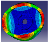
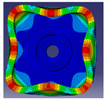
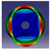
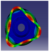
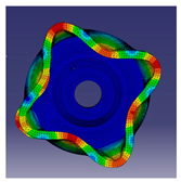
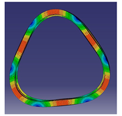
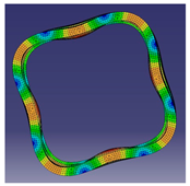
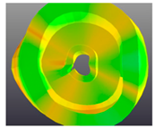
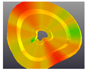
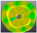
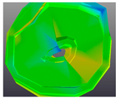
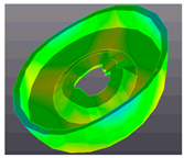
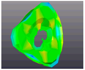
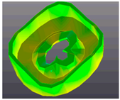
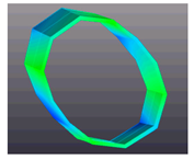
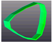
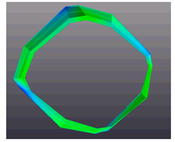
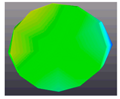
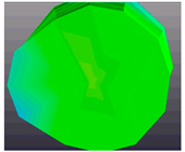
It is well known that in electrical machines, the radial forces produced by the rotor act on the stator. This phenomenon was investigated in detail in [47]. The electromagnetic forces applied on the stator influence its structure, and could have some damaging effects. One the most important effects is related to the structural deformations of the stator. These deformations are responsible for the appearance of the vibrations and noises during the operation of the system. If known, the resonant frequencies can be predicted and suppressed to mitigate the damaging effects or even avoid them completely. The deformations caused by vibrations are called modes or eigenmodes. As a function of the pressure applied on the structure, different deformations can occur, thus resulting in the modal shapes related to the number of pressure points. For example, the second modal shape has two points where the pressure is applied which “squeeze” the structure, determining an oval shape. The main modal shapes of a structure are shown in Table 5.
The analytical prediction of the structural frequencies is difficult because of the particularities of the stator (i.e., teeth, windings) [48,49]. In [50], a method to derive an analytical model of the stator was presented, considering its cylindrical shape and integrating the teeth and windings as part of the structure. Various papers [51,52,53,54] analyzed a method that considers the investigated structure as a cylindrical shell. A new method for the determination of frequencies, implemented for cylindrical shells of finite length, was investigated in [55]. However, the most practical and simple formula used to determine the natural frequency of a structure is based on the Donnel–Mushtari theory. The natural frequency of a cylindrical shell—the stator circumferential vibration of the m-th order, in this case—can be determined by using the general equation:
f m = 1 2 · π · K m M m
where Km and Mm are the lumped stiffness and lumped mass of the structure. The lumped mass parameter can be calculated with:
M m = π · ρ · D · l · h  
where ρ is the material density, D is the mean value of the cylindrical shell diameter, l is the cylindrical length and h is the wall thickness of the shell. The lumped mass can be determined by:
K m = 4 · m 2 D · π · l · h · E 1 v 2  
where v is Poisson’s ratio and Ω is the parameter determined by extracting the roots of second order of the motion equation. If the circumferential mode m is 1, then Ω0 = 1; in any other case, the parameter can be calculated by:
m = 1 2 · ( 1 + m 2 + k 2 m 4 ) ± ( 1 + m 2 + k 2 m 4 ) 2 4 k 2 m 6  
where k is the thickness parameter, which can be obtained by:
k 2 = h 2 3 · D 2  
By integrating the above equations, the natural frequency of m-th order can be determined with:
f m = m π · D · E ρ · ( 1 v 2 )    
The Donnel–Mushtari theory is more accurate than others, and in general, more reliable results can be obtained. In this paper, the structural analysis was performed for each active part of the IWM-IMG. Because the modal orders 2, 3 and 4 are the most relevant and noisy orders, they were calculated here for each part of the machine. The obtained values are presented in Table 6.
B.
Numerical Structural Analysis of the Studied IWM-IMG
Based on the results obtained from the analytical approach, the numerical analysis was performed. In general, the numerical results are more precise than the analytical ones and more accurately reflect the studied phenomena. Hence, numerical analysis has been widely used in recent decades [56,57]. The analytical methods are based on several assumptions and a simplified hypothesis [58]. The numerical analysis provides reliable results in comparison with the analytical one, but it is much more time-consuming. The main advantages of numerical analysis are the flexibility offered by the software packages as well as the capability to analyze complex models with complex physical phenomena, such as material saturation and anisotropy.
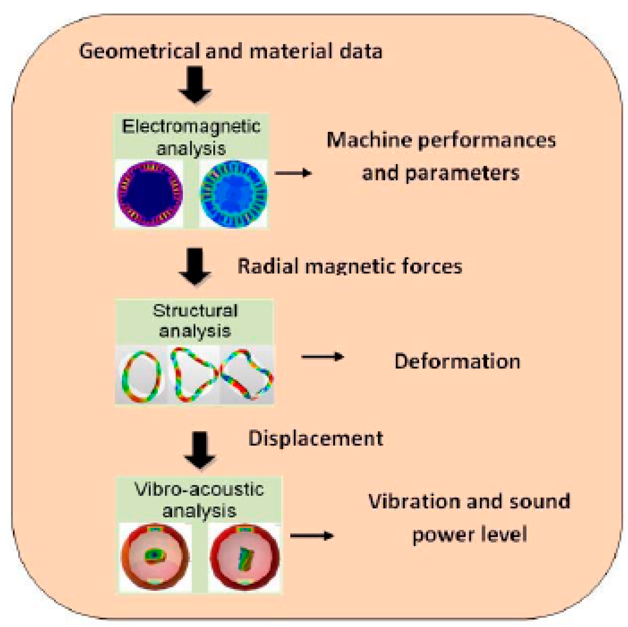
The numerical analysis was performed with two software packages for electromagnetic behavior evaluation and for vibration and noise analysis. The analysis processing flowchart is shown in Figure 4. After the performances of the machine and its parameters were obtained from the electromagnetic analysis, the radial magnetic forces that act on the investigated structure were computed. The response of the structure can be observed in terms of deformations, meaning the modal structural response. Then, the vibrations and sound power level can be depicted based on the deformations of the structure.
Depending on the application, the acoustic noise has different tonalities. For example, if the noise has a low frequency, the noise can be detected as a humming noise. On the other hand, if the noise frequency is high, it can be detected as a whining noise.
The numerical analysis was performed on the four components of the IWM-IMG (the stator and the rotor of the IWM, the inner and outer rotor of the IWM and its static part, denoted later with the SPP acronym) as well as on its whole assembled configuration. The main material characteristics used for this analysis are presented in Table 7.
A frequency range must be set to perform the modal shape analysis. The analysis is considered for a preset frequency or for a set number of modes, depending on the requirements of the applications. For this analysis, a range of frequency between 0 and 8000 Hz was chosen for each structure. The forces acting on the structure create a pressure, and the response of the structure is called the force response. This is responsible for the deformation that appears and forces the structure to take on different strange shapes. These deformations represent vibration producers, which are responsible for the noise emitted in the surrounding area.
The structural response of an entity depends very much on the mechanical shape and its material. For example, a fuller shape object has increased stiffness compared to a shell-type object. Moreover, two attached objects influence one another. The influence is even bigger if the objects have different shapes and are made of different materials. Considering these facts, the structural analysis must be made separately on each component of the structure. In this way, it is possible to observe the structural and acoustic response of each part and to evaluate its impact on the behavior of the entire structure.
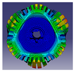
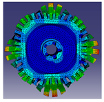
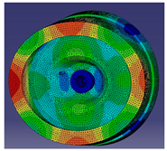
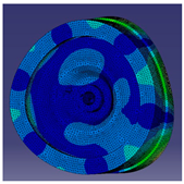
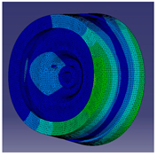
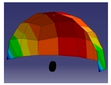
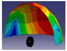
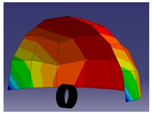
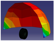
The main modal orders (2, 3 and 4) for each active part and for the entire structure are depicted in Table 8. The frequency of modal orders is specified for each structure.
The first results of the numerical vibro-acoustic analysis presented above represent the mode shapes of the structure. As was already mentioned, the analysis took into consideration the four main parts of the IWM-IMG. The reason for the detailed analysis is because of the complex structure of the integrated MG. It is known that the IWM is a quiet machine [59], but a deeper analysis is necessary for this structure due to the presence of a doubled rotor and other supplementary elements.
The main sources of noise in electrical motors are divided into three main categories: aerodynamic, mechanical and electromagnetic [60]. Each of these sources was analyzed in various studies [61,62]. The level of noise produced by an electromagnetic source is greatly dependent on the geometrical parameters of the machine, such as dimensions of slots and poles, airgap length [63], ratio between housing outer diameter and height of the yoke [64]. Additionally, a source of electromagnetic noise is represented by the static converters. Various papers [51,65] prove that the supply from the inverter produces harmonics, because the waveform of the voltage is not purely sinusoidal. The level of noise, in the case of the motors supplied by an inverter, is because of the superimposed resonance between the magnetic force frequency and the natural frequency.
The emitted noise was investigated, and the acoustic analysis results for each of the four parts of the structure are presented in Table 9.
The acoustic pressure is depicted at 1 m distance on the shell surface of the surrounding area. The maximum value of acoustic pressure for the stator is 73.5 dB, which corresponds to 238 Hz, which is double that of the fed frequency. These high levels of acoustic pressure were occurring at multiples of the fed frequency, which means that none of the resonance frequencies were particularly excited.
The results of the numerical analysis for the entire structure at 100 cm distance of acoustic pressure are presented in Table 8. Other scenarios are made for different distances, i.e., 70 cm and 10 cm. The values of sound power level are compared with the experimental ones in the next section, where three microphones are placed at three different distances. The purpose of setting different distances is to observe how much the acoustics are affected by the distances between the emitter and the receptor. Furthermore, different values of switching frequency were studied. The first set of simulations for a distance from 10 to 100 cm made for 8 kHz and 20 kHz are shown in Table 10.
C.
Experimental Structural Analysis of the Studied IWM-IMG
Although the IWM is a quiet machine, the presence of the MG in the structure may lead to significant changes that can produce a level of noise higher than expected. Hence, to validate the numerical results, experimental measurements must be performed. Two types of experimental measurements were considered: impact tests for vibrations and run-up tests.
C.1.
Impact test of the IWM-IMG
The impact test is necessary to determine the structural response of the investigated probe. The structure is placed under the influence of a force which causes the bending or deformation of the object. These modified patterns of the structure can be visualized in an analysis, performed with a software package dedicated to structural analysis.
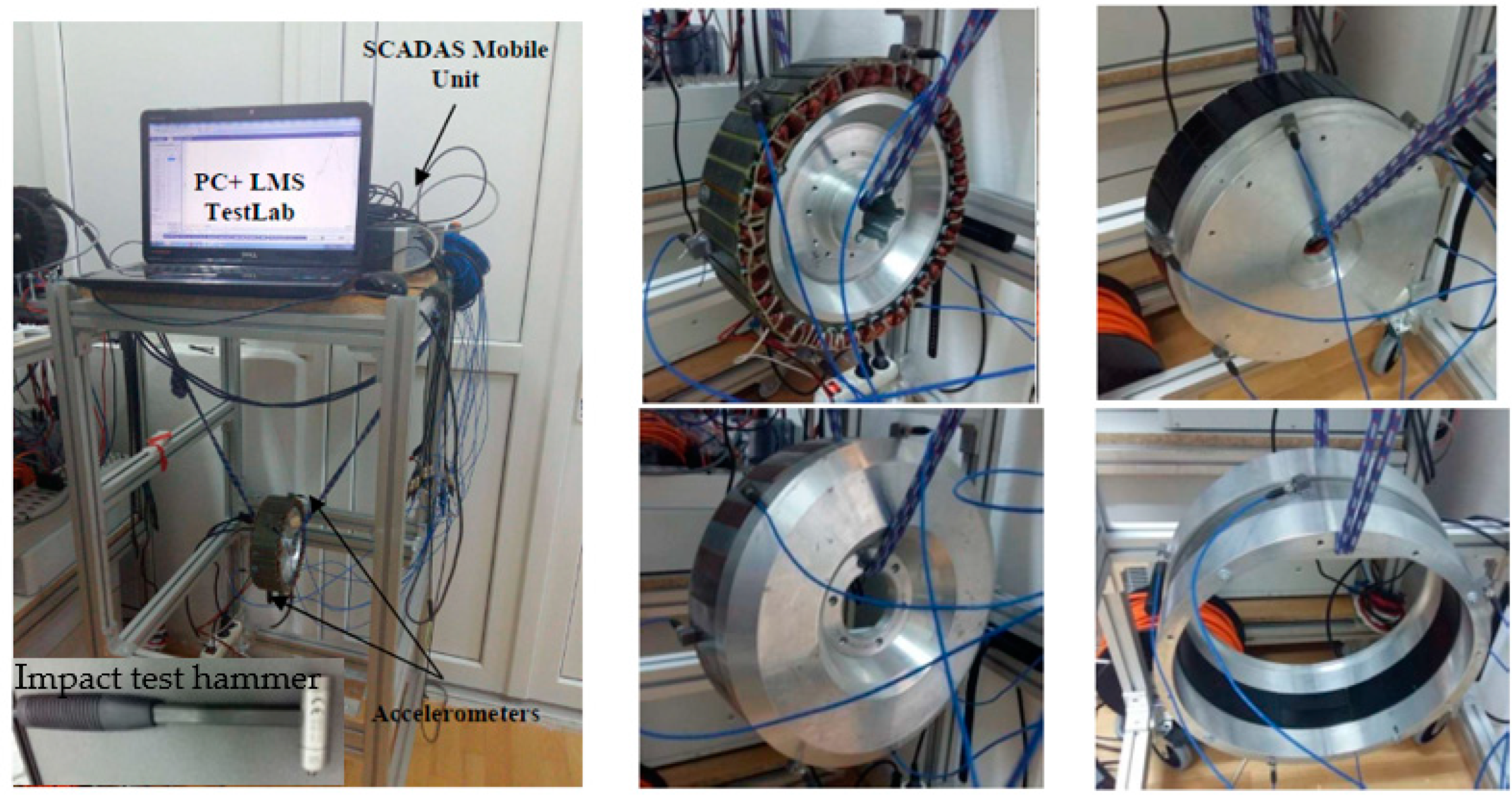
First, the probe is suspended by a semi-elastic rope, without any constraints of movement (see Figure 5). The test for a pure structural response must be performed in free-to-free conditions, without any contact between the probe and another surface. The accuracy of the results is influenced by the additional elements, if there is at least some contact. For example, if the probe is attached to another piece, the structural response is only in one direction because the other piece is restricting the structural response in that direction. Six sensors are placed at some specific points to detect the response of the structure. To avoid increasing the mass of the probe, the use of a small number of accelerometers is recommended. The probe is excited with an impact hammer.
Based on the measurements of the impact tests, the software provides a graphical structure response. The main modal shapes for each structure and the frequency value of modal orders are shown in Table 11. The highest value of frequency of an analyzed part was reached by the stator because this is a solid shape and it has a higher damping factor due to its high material density (for example, for mode 2, this value is 1383 Hz). However, as it can be noticed, the entire structure reached an even higher frequency.
C.2.
Acoustic tests
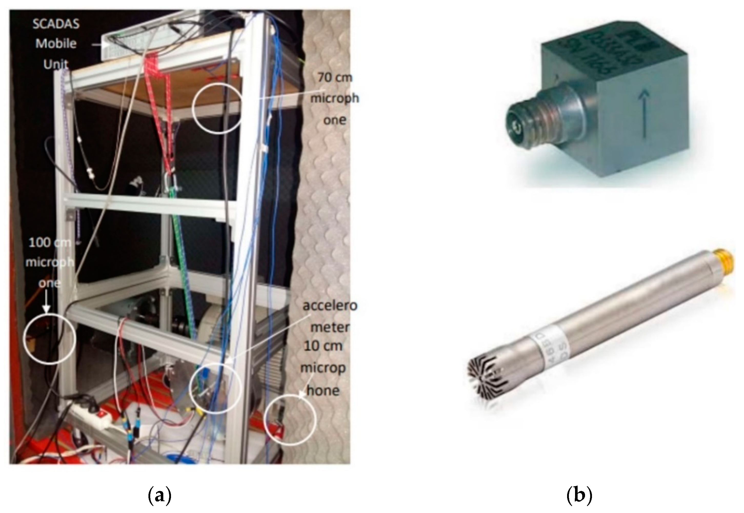
The determination of the noise level was the next objective in our study. The used tools are presented in Figure 6. First, the probe was suspended by a semi-elastic rope, as in the previous tests. The difference is that now the probe is placed into a semi-anechoic chamber to avoid interference from the outer noise. A PCB accelerometer was placed on the outer surface of the probe to detect the structure’s response. Three microphones placed in different places in the chamber were used to record the noise emitted by the investigated structure. The first microphone was placed just 10 cm from the structure to detect the noise emitted in the nearest area. The second and third microphones were placed 70 cm and 100 cm, respectively, from the structure to record the noise at greater distances (100 cm being the standard measuring distance). The measuring set-up and the main tools are presented in Figure 5, and the three microphones used are shown in Figure 6. The tests were made for each active part of the structure and separately, for the entire unit, in no-load conditions and at a rated speed. The tests were performed for two measuring scenarios: first, when the entire structure was fed from a programable power source, and second, when the batteries were the fed source (in order to avoid, as much as possible, the chopping effect produced by the programable source) via a three-phase inverter in both cases.
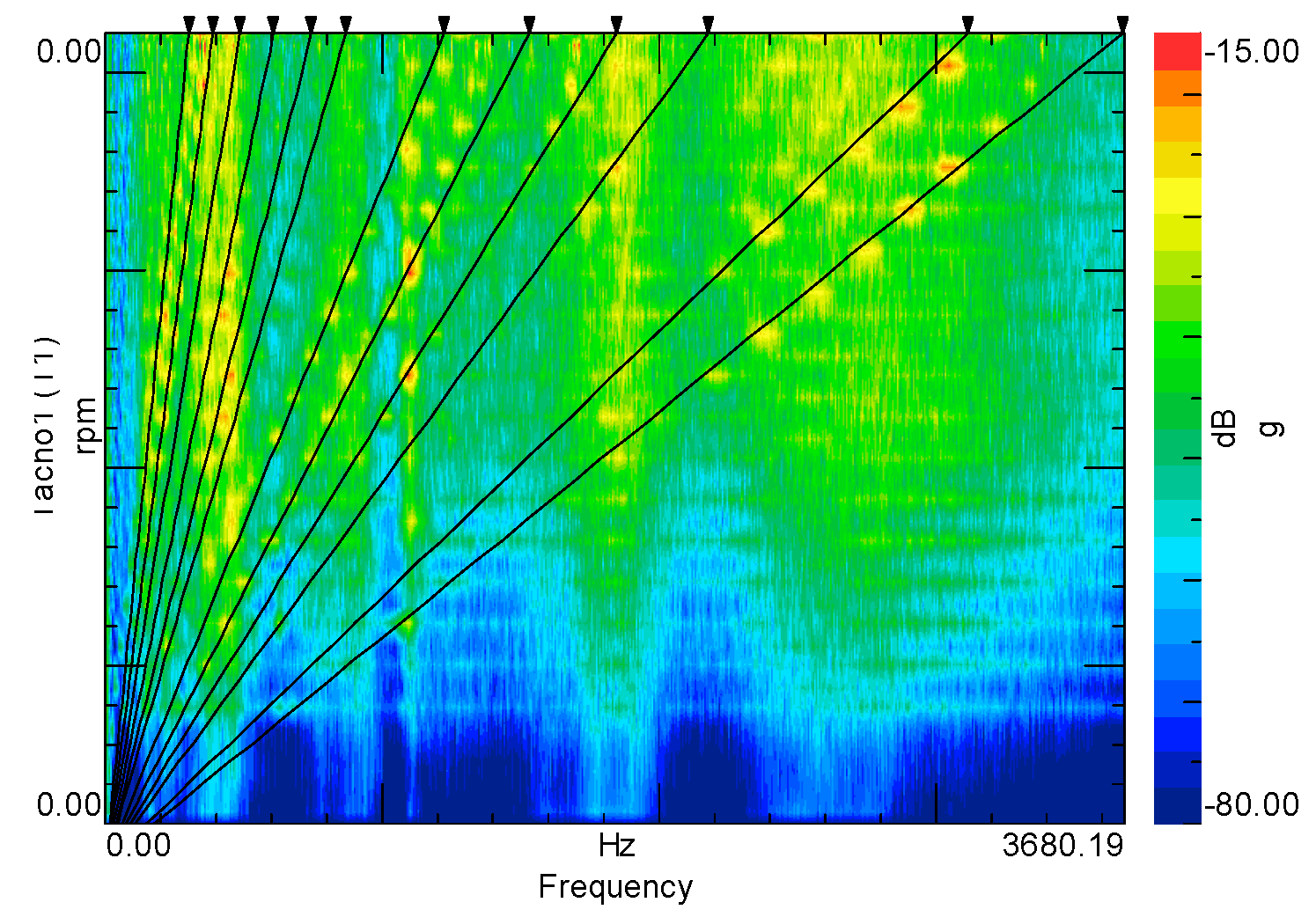
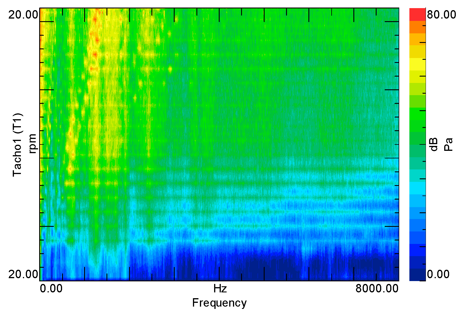
The first results of the tests are shown in Figure 7. The machine orders represented with oblique lines are presented here. These orders, also known as machine harmonics, are related to the rotational speed of the structure, the number of stator slots and the number of poles of the stationary part of the structure (SPP). Hence, they are multiples of slot numbers. The resonant frequencies represented with vertical lines are shown in Figure 8. The main resonant frequencies are related to the modal orders of the structure and appear as a high value of emitted noise.
The structure vibrations are strictly related to the machine performances because they can have a significant impact and they can influence the parameters of the IWM-IMG in a negative way. The vibrations are responsible for noise production, which can be annoying for the human ear.
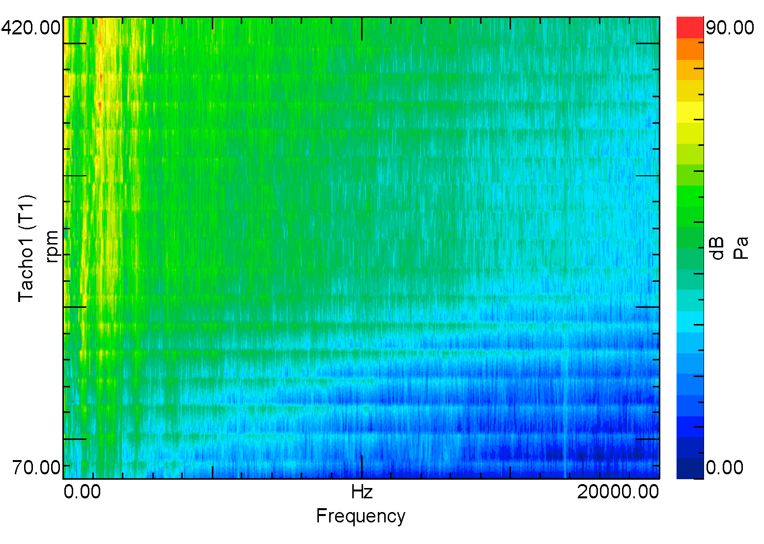
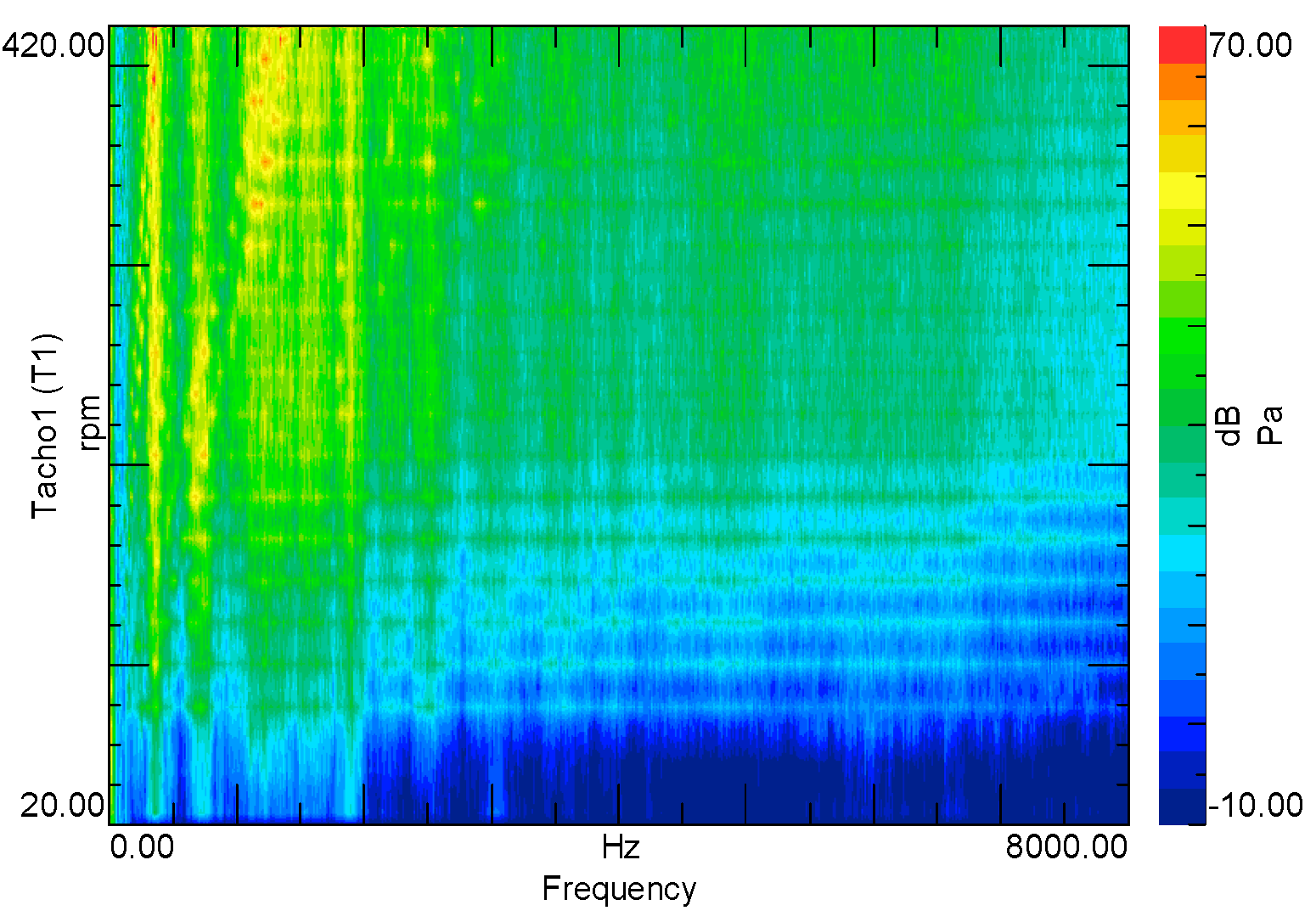
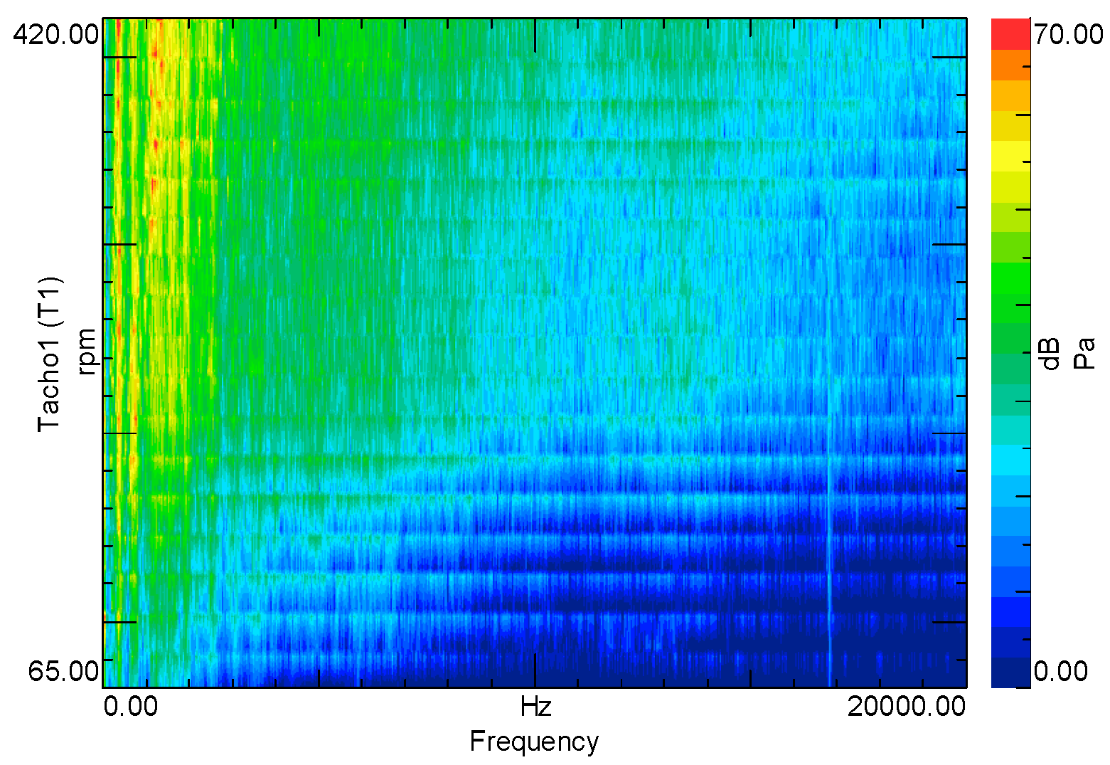
The noise emitted by the structure was investigated for different frequencies and depicted at different distances. Figure 9, Figure 10, Figure 11, Figure 12, Figure 13 and Figure 14 represent the waterfall maps for noise emitted for 8 kHz and 20 kHz. Each of the three microphones captured the noise emitted by the structure at either 10, 70 or 100 cm for each level of frequency.
The last one, the 100 cm distance microphone, is the recommended distance for measuring the noise because this is the common distance where the noise emitted has the most significant value for a human observer, based on the standards of the automotive industry.
As one can observe, the difference between the closest and the farthest microphone is related to the switching frequency. For the 8 kHz switching frequency, the noise level difference is just 5 dB between the different microphones. For the 20 kHz frequency, the difference is 10 dB. For 100 cm, the noise emitted is the same, even if the frequency is different. The difference appears to be at the closest microphone, where there is a 10 dB difference between the switching frequency of 8 kHz and 20 kHz. A maximum level of 90 dB of emitted noise was depicted, based on the acoustic tests performed on the analyzed structure, which is not a disturbing level.

4. Discussions

A complex structure of a magnetic gear placed on top of an in-wheel motor was investigated in this article. The structure was presented in light of other existing topologies found in the scientific literature, emphasizing its originality. Such a system is to be used for electric vehicle applications, having, among others, the advantage of offering two levels of torque and speed. The main electromagnetic design elements were introduced in order to prove the suitability of the proposed propulsion system, based on the obtained characteristics and performances. Moreover, the vibro-acoustic analysis, employed through analytical, numerical and experimental means, were presented in detail. The comparison of these results has proved the validity of the analysis, justifying the suitability of the structure for the considered application. To emphasize the achievements of the study, all the results obtained for the structural analysis are presented in Table 12. The comparison is performed separately for each active part of the studied topology, as well as for the entire structure. The mode number and the occurred frequency value for each structure are shown.
The results of the numerical analysis and experimental acoustic tests for the studied structure, for two frequency levels and for three distances, are shown in Table 13. It was proved that the obtained results validate the study, since no structure’s resonance was superimposed with the frequencies of the static inverter, and the level of produced noise is not disturbing, being in the limits of the application.

Author Contributions

Conceptualization, C.V.P. and D.F.; methodology, C.V.P., D.F. and D.-C.P.; validation, C.V.P. and D.F.; formal analysis, D.-C.P.; investigation, C.V.P.; resources, D.F; writing—original draft preparation, C.V.P. and D.-C.P.; writing—review and editing, C.V.P., D.F. and D.-C.P.; funding acquisition, D.F. All authors have read and agreed to the published version of the manuscript.

Funding

This paper was financially supported in part by the Technical University of Cluj-Napoca, as well as through the project “Entrepreneurial competence and excellence research in doctoral and postdoctoral programs—ANTREDOC”, co-funded by the European Social Fund, agreement no. 56437/24.07.2019.

Institutional Review Board Statement

Not applicable.

Informed Consent Statement

Not applicable.

Data Availability Statement

Not applicable.

Conflicts of Interest

The authors declare no conflict of interest.

References

  1. Huang, B.; Hu, M.; Zeng, L.; Fu, G.; Jia, Q. Design Method for Hybrid Electric Vehicle Powertrain Configuration with a Single Motor. Sustainability 2022, 14, 8225. [Google Scholar] [CrossRef]
  2. Xu, S.; Wei, L.; Zhang, X.; Bai, Z.; Jiao, Y. Research on Multi-Mode Drive Optimization Control Strategy of Four-Wheel-Drive Electric Vehicles with Multiple Motors. Sustainability 2022, 14, 7378. [Google Scholar] [CrossRef]
  3. Wang, R.; Xing, Q.; Chen, Z.; Zhang, Z.; Liu, B. Modeling and Analysis of Electric Vehicle User Behavior Based on Full Data Chain Driven. Sustainability 2022, 14, 8600. [Google Scholar] [CrossRef]
  4. Manutworakit, P.; Choocharukul, K. Factors Influencing Battery Electric Vehicle Adoption in Thailand—Expanding the Unified Theory of Acceptance and Use of Technology’s Variables. Sustainability 2022, 14, 8482. [Google Scholar] [CrossRef]
  5. Muzir, N.A.Q.; Mojumder, M.R.H.; Hasanuzzaman, M.; Selvaraj, J. Challenges of Electric Vehicles and Their Prospects in Malaysia: A Comprehensive Review. Sustainability 2022, 14, 8320. [Google Scholar] [CrossRef]
  6. Popa, D.C.; Fodorean, D. Design and performances evaluation of a high speed induction motor used for the propulsion of an electric vehicle. In Proceedings of the SPEEDAM 2014—Symposium on Power Electronics, Electrical Drives, Automation and Motion, Ischia, Italy, 18–20 June 2014; pp. 88–93. [Google Scholar]
  7. Fodorean, D. State of the art of magnetic gears, their design, and characteristics with respect to EV application. In Modeling and Simulation for Electric Vehicle Applications; IntechOpen: Rijeka, Croatia, 2016. [Google Scholar]
  8. Jørgensen, F.T.; Andersen, T.O.; Rasmussen, P.O. The cycloid permanent magnetic gear. In Proceedings of the Conference Record of the 2006 IEEE Industry Applications Conference Forty-First IAS Annual Meeting, Tampa, FL, USA, 8–12 October 2006; IEEE: Piscataway, NJ, USA, 2006; pp. 373–378. [Google Scholar]
  9. Armstrong, C.G. Power Transmitting Device. U.S. Patent 687292, 26 November 1901. [Google Scholar]
  10. Faus, H.T. Magnet Gearing. U.S. Patent 2243555, 27 May 1941. [Google Scholar]
  11. Rand, S. Magnetic Transmission System. U.S. Patent 3523204, 4 August 1970. [Google Scholar]
  12. Hetzel, M. Low Friction Miniature Gear Drive for Transmitting Small Forces, and Method of Making Same. U.S. Patent 3792578, 19 February 1974. [Google Scholar]
  13. Ikuta, K.; Makita, S.; Arimoto, S. Non-contact magnetic gear for micro transmission mechanism. In Proceedings of the [1991] Proceedings, IEEE Micro Electro Mechanical Systems, Nara, Japan, 30 December 1990–2 January 1991; IEEE: Piscataway, NJ, USA, 1991; pp. 125–130. [Google Scholar]
  14. Furlani, E.P. A two-dimensional analysis for the coupling of magnetic gears. IEEE Trans. Magn. 1997, 33, 2317–2321. [Google Scholar] [CrossRef]
  15. Kikuchi, S.; Tsurumoto, K. Design and characteristics of a new magnetic worm gear using permanent magnet. IEEE Trans. Magn. 1993, 29, 2923–2925. [Google Scholar] [CrossRef]
  16. Kikuchi, S.; Tsurumoto, K. Trial construction of a new magnetic skew gear using permanent magnet. IEEE Trans. Magn. 1994, 30, 4767–4769. [Google Scholar] [CrossRef]
  17. Atallah, K.; Howe, D. A novel high-performance magnetic gear. IEEE Trans. Magn. 2001, 37, 2844–2846. [Google Scholar] [CrossRef]
  18. Huang, C.; Tsai, M.; Lin, B. Development of new magnetic planetary gears for transmission systems. In Proceedings of the 2006 IEEE International Magnetics Conference (INTERMAG), San Diego, CA, USA, 8–12 May 2006; IEEE: Piscataway, NJ, USA, 2006; p. 225. [Google Scholar]
  19. Tsai, M.C.; Huang, C.C. Development of a variable-inertia device with a magnetic planetary gearbox. IEEE/ASME Trans. Mechatron. 2010, 16, 1120–1128. [Google Scholar] [CrossRef]
  20. Kong, F.; Ge, Y.; Zhu, X.; Qiao, L.; Quan, L. Optimizing design of magnetic planetary gearbox for reduction of cogging torque. In Proceedings of the 2013 IEEE Vehicle Power and Propulsion Conference (VPPC), Beijing, China, 15–18 October 2013; IEEE: Piscataway, NJ, USA, 2013; pp. 1–5. [Google Scholar]
  21. Rasmussen, P.O.; Andersen, T.O.; Jorgensen, F.T.; Nielsen, O. Development of a high-performance magnetic gear. IEEE Trans. Ind. Appl. 2005, 41, 764–770. [Google Scholar] [CrossRef]
  22. Li, X.; Chau, K.T.; Cheng, M.; Hua, W. Comparison of magnetic-geared permanent-magnet machines. Prog. Electromagn. Res. 2013, 133, 177–198. [Google Scholar] [CrossRef]
  23. Huang, C.C.; Tsai, M.C.; Dorrell, D.G.; Lin, B.J. Development of a magnetic planetary gearbox. IEEE Trans. Magn. 2008, 44, 403–412. [Google Scholar] [CrossRef]
  24. Wang, R.J.; Matthee, A.; Gerber, S.; Tlali, P. Calculation of torque performance of a novel magnetic planetary gear. IEEE Magn. Lett. 2016, 7, 1–5. [Google Scholar] [CrossRef]
  25. Rens, J.; Atallah, K.; Calverley, S.D.; Howe, D. A novel magnetic harmonic gear. IEEE Trans. Ind. Appl. 2009, 46, 206–212. [Google Scholar] [CrossRef]
  26. Takahara, K.; Hirata, K.; Niguchi, N.; Suzuki, H.; Kamigakiki, T.; Ukaji, H. Design of Radially-Differential Type Magnetic Harmonic Geared Motor. In Proceedings of the 19th International Symposium on Electromagnetic Fields in Mechatronics, Electrical and Electronic Engineering (ISEF), Nancy, France, 29–31 August 2019; pp. 1–2. [Google Scholar] [CrossRef]
  27. Mezani, S.; Atallah, K.; Howe, D. A high-performance axial-field magnetic gear. J. Appl. Phys. 2006, 99, 08R303. [Google Scholar] [CrossRef]
  28. Zhu, Z.Q.; Khatab, M.F.; Li, H.; Liu, Y. A novel axial flux magnetically geared machine for power split application. IEEE Trans. Ind. Appl. 2018, 54, 5954–5966. [Google Scholar] [CrossRef]
  29. Acharya, V.M.; Calvin, M.; Bird, J.Z. A low torque ripple flux focusing axial magnetic gear. In Proceedings of the 7th IET International Conference on Power Electronics, Machines and Drives (PEMD 2014), Manchester, UK, 8–10 April 2014; IET: London, UK, 2014; pp. 1–6. [Google Scholar]
  30. Acharya, V.M. Design of a Flux Focusing Axial Magnetic Gear. Master’s Thesis, Electrical and Computer Engineering, University North Carolina at Charlotte, Charlotte, NC, USA, December 2013. [Google Scholar]
  31. Venturini, M.; Leonardi, F. High torque, low speed joint actuator based on PM brushless motor and magnetic gearing. In Proceedings of the Conference Record of the 1993 IEEE Industry Applications Conference Twenty-Eighth IAS Annual Meeting, Toronto, ON, Canada, 2–8 October 1993; IEEE: Piscataway, NJ, USA, 1993; pp. 37–42. [Google Scholar]
  32. Hirata, K.; Yamamoto, M.; Muramatsu, M. Proposal of an axial gap magnetic gear. IEEJ Trans. Ind. Appl. 2010, 130, 802–807. [Google Scholar] [CrossRef]
  33. Li, W.; Chau, K.T. Analytical field calculation for linear tubular magnetic gears using equivalent anisotropic magnetic permeability. Prog. Electromagn. Res. 2012, 127, 155–171. [Google Scholar] [CrossRef] [Green Version]
  34. Ho, S.L.; Wang, Q.; Niu, S.; Fu, W. A novel magnetic-geared tubular linear machine with Halbach permanent-magnet arrays for tidal energy conversion. IEEE Trans. Magn. 2015, 51, 1–4. [Google Scholar]
  35. Niu, S.; Ho, S.L.; Fu, W.N. Performance analysis of a novel magnetic-geared tubular linear permanent magnet machine. IEEE Trans. Magn. 2011, 47, 3598–3601. [Google Scholar] [CrossRef]
  36. Holehouse, R.C.; Atallah, K.; Wang, J. A linear magnetic gear. In Proceedings of the 2012 XXth International Conference on Electrical Machines, Marseille, France, 2–5 September 2012; IEEE: Piscataway, NJ, USA, 2012; pp. 563–569. [Google Scholar]
  37. Chau, K.T.; Li, W.; Lee, C.H.T. Challenges and opportunities of electric machines for renewable energy. Prog. Electromagn. Res. B 2012, 42, 45–74. [Google Scholar] [CrossRef]
  38. Li, W.; Chau, K.T.; Jiang, J.Z. Application of linear magnetic gears for pseudo-direct-drive oceanic wave energy harvesting. IEEE Trans. Magn. 2011, 47, 2624–2627. [Google Scholar] [CrossRef]
  39. Mcgilton, B.; Crozier, R.; McDonald, A.; Mueller, M. Review of magnetic gear technologies and their applications in marine energy. IET Renew. Power Gener. 2018, 12, 174–181. [Google Scholar] [CrossRef]
  40. Feng, G.N.; Yu, H.; Huang, L.; Zhong, W.; Shi, Z. Performance analysis of a magnetic-geared linear permanent magnet generator for wave energy conversion. In Proceedings of the 2015 IEEE International Magnetics Conference (INTERMAG), Beijing, China, 11–15 May 2015; IEEE: Piscataway, NJ, USA, 2015; p. 1. [Google Scholar]
  41. Wang, Y.; Filippini, M.; Bianchi, N.; Alotto, P. A review on magnetic gears: Topologies, computational models, and design aspects. IEEE Trans. Ind. Appl. 2019, 55, 4557–4566. [Google Scholar] [CrossRef]
  42. Fodorean, D. Global design and optimization of a permanent magnet synchronous machine used for light electric vehicle. In Electric Vehicles—Modelling and Simulations; IntechOpen: Rijeka, Croatia, 2011. [Google Scholar]
  43. Pop, C.V.; Fodorean, D. In-wheel motor with integrated magnetic gear for extended speed applications. In Proceedings of the 2016 International Symposium on Power Electronics, Electrical Drives, Automation and Motion (SPEEDAM), Capri, Italy, 22–24 June 2016; IEEE: Piscataway, NJ, USA, 2016; pp. 413–418. [Google Scholar]
  44. Pop, C.V.; Fodorean, D. Purely Electromagnetic Propulsion System with Two Transmission Levels–Design, Numerical and Experimental Results. IEEE Trans. Ind. Electron. 2022, in press. [CrossRef]
  45. Pop, C.V.; Essaid, M.; Idoumghar, L.; Fodorean, D. Novel Differential Evolutionary Optimization Approach for an Integrated Motor-Magnetic Gear Used for Propulsion Systems. IEEE Access 2021, 9, 142114–142128. [Google Scholar] [CrossRef]
  46. Matyas, A.R.; Biro, K.A.; Fodorean, D. Multi-phase synchronous motor solution for steering applications. Prog. Electromagn. Res. 2012, 131, 63–80. [Google Scholar] [CrossRef]
  47. Chen, Y.; Zhu, Z.; Ying, S. Analysis and Control of Motor Noise; Zhejiang University Press: Hangzhou, China, 1987. [Google Scholar]
  48. Oravec, M.; Lipovský, P.; Šmelko, M.; Adamčík, P.; Witoś, M.; Kwaśniewski, J. Low-Frequency Magnetic Fields in Diagnostics of Low-Speed Electrical and Mechanical Systems. Sustainability 2021, 13, 9197. [Google Scholar] [CrossRef]
  49. Mori, D.; Ishikawa, T. Force and vibration analysis of induction motors. IEEE Trans. Magn. 2005, 41, 1948–1951. [Google Scholar] [CrossRef]
  50. Wang, T.Y.; Wang, F.X. Vibration and modal analysis of stator of large induction motors. Zhongguo Dianji Gongcheng Xuebao (Proc. Chin. Soc. Electr. Eng.) 2007, 27, 41–45. [Google Scholar]
  51. Gieras, J.F.; Wang, C.; Lai, J.C. Noise of Polyphase Electric Motors; CRC Press: Boca Raton, FL, USA, 2006. [Google Scholar]
  52. Wu, J.H. Study on the Stator Mode Shapes and Natural Frequencies of Switched Reluctance Motor Based on Real Structual Model. Proc. Chin. Soc. Electr. Eng. 2004, 24, 109–114. [Google Scholar]
  53. Yu, S.; Tang, R. Electromagnetic and mechanical characterizations of noise and vibration in permanent magnet synchronous machines. IEEE Trans. Magn. 2006, 42, 1335–1338. [Google Scholar]
  54. Wang, C.; Lai, J.C.S. Prediction of natural frequencies of finite length circular cylindrical shells. Appl. Acoust. 2000, 59, 385–400. [Google Scholar] [CrossRef]
  55. Hameyer, K.; Belmans, R. Numerical Modelling and Design of Electrical Machines and Devices; WIT Press: Southampton, UK, 1999. [Google Scholar]
  56. Kuczmann, M. Potential Formulations in Magnetics Applying the Finite Element Method; Lecture Notes; Laboratory of Electromagnetic Fields, “Széchenyi István” University: Gyor, Hungary, 2009. [Google Scholar]
  57. Strouboulis, T.; Babuška, I.; Copps, K. The design and analysis of the generalized finite element method. Comput. Methods Appl. Mech. Eng. 2000, 181, 43–69. [Google Scholar] [CrossRef]
  58. Pop, C.V.; Birte, O.; Fodorean, D. Noise and vibrations analysis of a permanent magnet synchronous machine for light electric vehicle. In Proceedings of the 2017 52nd International Universities Power Engineering Conference (UPEC), Heraklion, Greece, 28–31 August 2017; IEEE: Piscataway, NJ, USA, 2017; pp. 1–5. [Google Scholar]
  59. Fodorean, D.; Sarrazin, M.M.; Marţiş, C.S.; Anthonis, J.; van der Auweraer, H. Electromagnetic and structural analysis for a surface-mounted PMSM used for light-EV. IEEE Trans. Ind. Appl. 2016, 52, 2892–2899. [Google Scholar] [CrossRef]
  60. Yang, S.J. Low-Noise Electrical Motors; Clarendon Press: Oxford, UK, 1981. [Google Scholar]
  61. Bortnowski, P.; Król, R.; Nowak-Szpak, A.; Ozdoba, M. A Preliminary Studies of the Impact of a Conveyor Belt on the Noise Emission. Sustainability 2022, 14, 2785. [Google Scholar] [CrossRef]
  62. Rameshkumar, T.; Chandrasekar, P.; Kannadasan, R.; Thiyagarajan, V.; Alsharif, M.H.; Kim, J.H. Electrical and Mechanical Characteristics Assessment of Wind Turbine System Employing Acoustic Sensors and Matrix Converter. Sustainability 2022, 14, 4404. [Google Scholar] [CrossRef]
  63. Le Besnerais, J.; Lanfranchi, V.; Hecquet, M.; Romary, R.; Brochet, P. Optimal slot opening width for magnetic noise reduction in induction motors. IEEE Trans. Energy Convers. 2009, 24, 869–874. [Google Scholar] [CrossRef]
  64. Crocker, M.J. Handbook of Noise and Vibration Control; John Wiley & Sons: Hoboken, NJ, USA, 2007. [Google Scholar]
  65. Nau, S.L.; Mello, H.G.G. Acoustic noise in induction motors: Causes and solutions. In Proceedings of the Record of Conference Papers, Industry Applications Society 47th Annual Conference, 2000 Petroleum and Chemical Industry Technical Conference (Cat. No. 00CH37112), San Antonio, TX, USA, 13 September 2000; pp. 253–263. [Google Scholar]
Figure 1. Mechanical (left) and magnetic (right) gear topologies.
Sustainability 14 12007 g001
Figure 2. Cross-section of the proposed IWM-IMG (with a detailed look at its structure).
Sustainability 14 12007 g002
Figure 3. The main characteristics of the designed IWM-IMG: (a) axis torque; (b) input electrical power and fed current; (c) output power (IWM only, and with IMG); (d) efficiency (IWM only, or with IMG); (e) power factor of the IWM-IMG.
Sustainability 14 12007 g003
Figure 4. Flowchart of numerical analysis.
Sustainability 14 12007 g004
Figure 5. Laboratory set-up for impact test (left), with suspended probes (right).
Sustainability 14 12007 g005
Figure 6. (a) Measuring set-up for noise detection; (b) accelerometer and microphone.
Sustainability 14 12007 g006
Figure 7. Orders of harmonic frequency.
Sustainability 14 12007 g007
Figure 8. Frequency spectrum of vibration.
Sustainability 14 12007 g008
Figure 9. Microphone at 10 cm, switching frequency of 8 kHz.
Sustainability 14 12007 g009
Figure 10. Microphone at 10 cm, switching frequency of 20 kHz.
Sustainability 14 12007 g010
Figure 11. Microphone at 70 cm, switching frequency of 8 kHz.
Sustainability 14 12007 g011
Figure 12. Microphone at 70 cm, switching frequency of 20 kHz.
Sustainability 14 12007 g012
Figure 13. Microphone at 100 cm, switching frequency of 8 kHz.
Sustainability 14 12007 g013
Figure 14. Microphone at 100 cm, switching frequency of 20 kHz.
Sustainability 14 12007 g014
Table 1. The main data of the analyzed structure.
ParameterValueUnit
Number of phases3-
Supplying voltage48V
Supplying frequency (IWM)119Hz
Demanded output power1500W
Number of pole pairs (IWM and for the inner rotor MG)17-
Number of the pole pairs of the outer rotor (MG)5-
Stator slots number (IWM)39-
Static part slot teeth number (MG)22
Rated speed (IWM and inner rotor for MG)420r/min
Outer rotor speed (outer rotor speed for the MG)1428r/min
Rated torque34N∙m
Table 2. Specifications of the used materials.
MaterialProperty (Unit)ValueDensity (kg/m3)
CopperElectric resistivity (Ω∙m)2.438 × 10−88954
AirMagnetic permeability (m∙kg/A2∙s2)1.2566 × 10−80.9996 (at 100 °C)
NdFeBRemanent flux density (T)1.117400
Magnetic field coercivity (kA/m)9907
Relative magnetic permeability1.05
M530Flux density saturation limit (T)1.87800
Stacking coefficient of the steel sheets0.95
Conductivity of the steel sheets (A2∙s2/m3∙kg)4 × 106
Table 3. Main geometrical parameters of the designed IWM-IMG.
ParameterValueUnit
Outer diameter of outer rotor0.182m
Height of the PM0.003m
Height of the static teeth of the MG0.014m
Outer diameter of the stator0.199m
Inner diameter of the stator0.153m
Table 4. Comparison of the proposed IWM-IMG and the IWM with a separate MG.
CriterionIWM + Separate Mechanical GearProposed IWM-IMG
Mass48 kg32.3 kg
Strong pointNot expensiveRobustness, Efficiency
Weak pointWeak volume and efficiencyExpensive
Table 5. Modal deformation shapes of a cylindrical structure.
Mode Number12345
Modal shapeSustainability 14 12007 i001Sustainability 14 12007 i002Sustainability 14 12007 i003Sustainability 14 12007 i004Sustainability 14 12007 i005
Table 6. Circumferential natural frequencies of the IWM-IMG structure.
StructureModal OrderFrequency (Hz)
Stator21491
32750
44592
Inner rotor2802
31137
42949
SPP2649
31551
42819
Outer rotor2440
31561
42838
MG21694
33123
45938
Table 7. Main characteristics of the used materials for the structural analysis of the IWM-IMG.
DescriptionMaterial
AluminumSteelNdFeB
Density (Kg/m3)271078607500
Young modulus (N/m2)7 × 10102 × 10111.6 × 1012
Poisson’s ratio0.3460.2660.24
Table 8. Modal orders of active parts of the studied IWM-IMG.
Mode 2Mode 3Mode 4
StatorSustainability 14 12007 i006
1419 Hz
Sustainability 14 12007 i007
3068 Hz
Sustainability 14 12007 i008
4680 Hz
Inner rotorSustainability 14 12007 i009
838 Hz
Sustainability 14 12007 i010
1810 Hz
Sustainability 14 12007 i011
2906 Hz
SPPSustainability 14 12007 i012
788 Hz
Sustainability 14 12007 i013
1547 Hz
Sustainability 14 12007 i014
2416 Hz
Outer rotorSustainability 14 12007 i015
539 Hz
Sustainability 14 12007 i016
1482 Hz
Sustainability 14 12007 i017
2730 Hz
IWM-IMGSustainability 14 12007 i018
2047 Hz
Sustainability 14 12007 i019
3033 Hz
Sustainability 14 12007 i020
5061 Hz
Table 9. Acoustic level of noise on the components of the studied IWM-IMG, in dB.
StatorSustainability 14 12007 i021Sustainability 14 12007 i022
Inner rotorSustainability 14 12007 i023Sustainability 14 12007 i024
SPPSustainability 14 12007 i025Sustainability 14 12007 i026
Outer rotorSustainability 14 12007 i027Sustainability 14 12007 i028
IWM-IMGSustainability 14 12007 i029Sustainability 14 12007 i030
Table 10. Values of acoustic behavior of the IWM-IMG at different measuring distances.
Distance (cm)Frequency (Hz)Sound Power Level (dB)
100882.1
70887.3
10891.2
Table 11. Modal orders of the investigated structures of the IWM-IMG.
Mode 2Mode 3Mode 4
StatorSustainability 14 12007 i031
1393 Hz
Sustainability 14 12007 i032
3040 Hz
Sustainability 14 12007 i033
4668 Hz
Inner rotorSustainability 14 12007 i034
790 Hz
Sustainability 14 12007 i035
1751 Hz
Sustainability 14 12007 i036
2676 Hz
SPPSustainability 14 12007 i037
637 Hz
Sustainability 14 12007 i038
1197 Hz
Sustainability 14 12007 i039
2228 Hz
Outer rotorSustainability 14 12007 i040
435 Hz
Sustainability 14 12007 i041
1203 Hz
Sustainability 14 12007 i042
2236 Hz
IWM-IMGSustainability 14 12007 i043
1542 Hz
Sustainability 14 12007 i044
3722 Hz
Sustainability 14 12007 i045
6225 Hz
Table 12. Comparison of the obtained structural response values.
ParameterAnalyticalFEMExperimental Tests
Stator structural
response
2–1491 Hz2–1347 Hz2–1393 Hz
3–2750 Hz3–2934 Hz3–3040 Hz
4–4592 Hz4–4398 Hz4–4668 Hz
Inner rotor structural response2–802 Hz2–838 Hz2–790 Hz
3–1137 Hz3–1810 Hz3–1751 Hz
4–2949 Hz4–2784 Hz4–2676 Hz
SPP structural
response
2–649 Hz2–623 Hz2–637 Hz
3–1551 Hz3–1329 Hz3–1197 Hz
4–2819 Hz4–2145 Hz4–2228 Hz
MG outer rotor structural response2–440 Hz2–429 Hz2–435 Hz
3–1561 Hz3–1182 Hz3–1203 Hz
4–2838 Hz4–2177 Hz4–2236 Hz
IWM-IMG structural
response
2–1694 Hz2–1502 Hz2–1542 Hz
3–3123 Hz3–3593 Hz3–3722 Hz
4–5938 Hz4–5865 Hz4–6225 Hz
Table 13. Results of the numeric analysis and experimental tests for the MG.
ResultsDistance of Measurement (cm)Frequency (kHz)Noise Level (dB)
FEM10891.2
7087.3
10082.1
Experimental tests10880
7075
10070
FEM1020101
7094.5
10087.3
Experimental tests102090
7080
10070
Publisher’s Note: MDPI stays neutral with regard to jurisdictional claims in published maps and institutional affiliations.