Article

Remaining Fatigue Life Predictions of Railway Prestressed Concrete Sleepers Considering Time-Dependent Surface Abrasion

1
Department of Civil Engineering, School of Engineering, University of Birmingham, Birmingham B15 2TT, UK
2
TOFU Lab (Track Engineering and Operations for Future Uncertainties), School of Engineering, University of Birmingham, Birmingham B15 2TT, UK
3
Structural Engineering Institute, East China Architectural Design & Research Institute, Shanghai 200002, China
4
Railway Engineering Institute, China Academy of Railway Sciences, Beijing 100081, China
*
Author to whom correspondence should be addressed.
Sustainability 2022, 14(18), 11237; https://doi.org/10.3390/su141811237
Submission received: 3 August 2022 / Revised: 2 September 2022 / Accepted: 3 September 2022 / Published: 8 September 2022
(This article belongs to the Special Issue Innovations in Durability of Sustainable Concrete Materials)

Abstract

:
One of the safety-critical components of ballasted track systems is railway sleepers whose main functions are to (i) transfer vertical load, (ii) maintain rail gauge, and (iii) restrain longitudinal rail movement. Railway sleepers can be manufactured using timber, concrete, steel, composite, and any other engineered materials. Prestressed concrete sleepers are the most commonly used type worldwide because of their superior value-for-money performance. In practice, railway sleepers experience thousands of cycles of aggressive wheel–rail dynamic loads and wear deterioration can be observed over their service life. Not only does the deterioration affect track quality and geometries, but it also undermines the structural integrity of the track structures. The wear and abrasion directly decrease the capacity of railway sleepers, resulting in the reduction in service life. In this paper, the emphasis is placed on the assessment of the fatigue life of prestressed concrete railway sleepers with imperfect geometry. This study is the world’s first to establish a new fatigue simulation of railway concrete sleepers considering accumulative non-constant amplitudes, which has been validated using full-scale experimental results and empirical analyses. Parametric studies have been conducted to obtain new insights into the fatigue performance of the worn sleepers. The new findings will improve railway sleeper maintenance and inspection criteria, and will provide a new guideline on track-condition monitoring networks.

1. Introduction

At present, railway transport is one of the most sustainable and commonly used forms of transport for passengers and goods [1]. Conventional ballasted track systems can be divided into superstructures and substructures. The superstructure includes the rails, fastening systems, railway sleepers, rail pads, and ballast. The substructure consists of the sub-ballast, formation, subgrade, and structural fills. A railway sleeper is a safety-critical component, which transfers the force from the wheels to the substructure [2,3,4]. Prestressed concrete sleepers are the most widely used type of sleeper materials because of their good structural performance, low cost, and ease of maintenance [5]. However, repeated loads from wheel–rail interactions could result in accumulated damage on railway sleepers, which reduces the service life. Both the static and dynamic load-carrying capacities of railway sleepers can degrade over time. In addition, early deterioration could lead to premature failure of railway sleepers. Such problems are a form of serviceability limit states, which have become of great concern over the past few decades for railway engineers. The most common causes of concrete sleeper failures have been ranked using the results obtained from a worldwide survey shown in Table 1 [6,7], where it can be seen that deterioration, abrasion, fatigue, and cracking are the most critical problems for railway sleepers. Such problems can lead to a combined reaction that accelerates the failure of railway sleepers. In limit-states design practice, the fatigue limit state shall be considered.
In order to investigate the serviceability performance of prestressed concrete sleepers, the dynamic condition needs to be investigated. In reality, a dynamic load is usually related to the rail–wheel interaction and train speed [8]. Railway sleepers often experience impact loading due to wheel–rail interactions associated with abnormalities in either a wheel or a rail [9]. The high dynamic impact forces induced by wheel–rail irregularities could greatly exceed the static wheel load, which could cause deterioration. The most common forms of wear are rail-seat or soffit abrasion at mid-span [10]. These deterioration mechanisms can be observed in the field. Extensive experimental and analytical investigations have been conducted by Kaewunruen and Remennikov on the dynamic behavior of prestressed concrete sleepers [11,12,13]. In their research, the impact damage and failure patterns of prestressed concrete sleepers were studied, which provided a database for life cycle investigation. Chen et al. presented an experimentally validated three-dimensional finite element model of a prestressed concrete sleeper that can be used to study and improve the design and performance [14]. Bastos et al. investigated the deterioration of prestressed concrete sleepers under cyclic loads and exposed to moisture [15]. Parvez et al. investigated the efficiency of using steel fibers to improve the fatigue performance of prestressed concrete sleepers [16]. Riding et al. conducted a study of environmental and track factors that influenced the abrasion damage of prestressed concrete sleepers [17]. Kernes et al. investigated the mechanics of rail-seat deterioration and methods to improve the abrasion resistance of concrete sleepers at rail seats [18]. It is noted that, for high-quality concrete sleepers, most studies did not observe any bond slip in the prestress wires under static and high-cycle fatigue tests. This is due to the fact that, in various modern design standards (such as in Europe, Australia, Japan, and China), there is a restriction in the allowable dimension of the prestress wires which helps it to increase the total bond perimeters and restrict any slip. In recent studies, Ngamkhanong et al. studied the effect of surface abrasion on the impact capacity of prestressed concrete sleepers [19,20]. Meanwhile, You et al. developed a nonlinear finite element model for determining the structural capacity of a prestressed concrete sleeper with rail-seat abrasion [21]. Further, Li et al. investigated creep and shrinkage of prestressed concrete sleepers influenced by surface abrasion [22]. Despite a number of previous studies into concrete sleepers and fatigue life, most studies focus on a general understanding in order to establish an empirical fatigue-life estimation that is relatively specific to the cases. On this ground, many factors related to time-dependent variables (such as wear, creep, and shrinkage, and so on) cannot be properly identified. This study has thus embarked on the development of nonlinear models of concrete sleepers capable of fatigue failure analyses and for virtual tests of the time-dependent factors.
Numerous numerical and experimental investigations have been initially conducted to establish rational railway-sleeper models by the authors [23]. Our studies into the fatigue life of concrete sleepers originated with the damage accumulation method [24,25]. This tailored method is extended from Miner’s rule. Traditionally, the cumulative damage under various loads is regarded as equivalent fatigue stress with constant amplitude [26]. Our study is unique in the way that the fatigue rule has been modified to enable iterative and variable stress fields (or non-constant amplitude), which can be more realistic and suitable for track load spectra. The critical literature review reveals that the fatigue life-cycles of prestressed concrete sleepers have not been fully studied, especially when the sleepers are deteriorated by excessive wear [27,28]. This paper is thus the world’s first to investigate and present an advanced railway concrete-sleeper model capable of parametric analysis into the effect of surface abrasion on the fatigue life of prestressed concrete sleepers. This model is highly original since it can cope with the accumulative, non-constant amplitudes of fatigue loads. The emphasis of this paper is placed on the fatigue life of prestressed concrete sleepers when subjected to wear or abrasion in comparison with intact railway sleepers. The new findings and insights will help track engineers to have a better understanding of the remaining fatigue life of damaged sleepers and provide a guideline to identify appropriate damage-detection technology for track systems. The new insight into fatigue life will also improve the safety and reliability of railway infrastructure.

2. Theoretical Life-Cycle Assessment Method of Prestressed Concrete Sleepers

2.1. Damage Accumulation Method

You et al. [29,30] demonstrated a new approach based on the damage accumulation method to analyze the life-cycle of prestressed concrete sleepers. The cumulative damage index is calculated by Miner’s rule:
D i = i n ( Δ σ i ) N ( Δ σ i )
where n ( Δ σ i ) is the applied number of cycles at a stress range Δ σ i ; N ( Δ σ i ) is the resisting number of cycles at a stress range Δ σ i .
The fatigue life can be determined by:
L f = 1 D i

2.2. Material Properties of Fatigue

The S–N curve can be defined as the number of cycles to failure when a material is repeatedly loaded through an alternating stress range. Therefore, the fatigue life of prestressed concrete sleepers can be determined as the maximum applied number of cycles to failure. [24,31]. The typical S–N curve for concrete and prestressing tendons is illustrated in Figure 1 and Figure 2.
S c ,   m a x = | σ c , m a x | f c k , f a t
S c ,   m i n = | σ c , m i n | f c k , f a t
where S c ,   m a x is the maximum compressive stress level; S c ,   m i n is the minimum compressive stress level; σ c , m a x is the maximum compressive stress; σ c , m i n is the minimum compressive stress; f c k , f a t is the fatigue-reference compressive strength.
If ( Δ σ > Δ σ N )
log N f = log N k 1 [ log ( Δ σ ) log ( Δ σ N ) ]
If ( Δ σ < Δ σ N )
log N f = log N + k 2 [ log ( Δ σ N ) log ( Δ σ ) ]
where Δ σ is the stress range of the prestressing steel; Δ σ N is the stress range at N cycles; k 1 , k 2 are the stress exponents. Table 2 illustrates the parameters of prestressing steel S–N curve.

2.3. Fatigue Life Assessment

In fatigue life assessment, there are two steps: cracking load calculation and fatigue life calculation. Initially, the stress range at the bottom fiber needs to be analyzed by:
σ c F b = n A p s σ s e A t + n A p s σ s e e I t y t
where σ s e is the effective stress at each prestressing steel; A p s is the cross-section area of a prestressing steel; e is the eccentricity; A t is the transformed area of the sleeper; I t is the inertia moment of transformed section before cracking; y t is the distance of the centroidal axis of the transformed area from the soffit.
The cracking moment is calculated by:
M c r = I t σ c F b + f c f y t
where f c f is the tensile strength.
The neutral axis of the cross-section of the sleeper starts changing when the cracking propagates. Therefore, the distance from the center of gravity of the effective transformed area to the top of the compressed area can be calculated by:
y C G = r o o t [ [ S p c I I n e A p 3 ( h y c g d 3 ) n e A p 2 ( h y c g d 2 ) n e A p 1 ( h y c g d 1 ) ] , y c g ]
where the S p c I I is the first moment at the bottom fiber after cracking; A p i is the total area of the prestressed steel at layer i; d i is the distance from the prestressed steel at layer i to the bottom of the steel area; and n e is the modular ratio.
The effective transformed section can be estimated using the transformed area of the sleeper cross-section A c I I :
A t I I = A c I I + n e A p
The moment of inertia of the cracking section is presented by:
I c r = I c c r + n e A p 3 ( h y c g d 3 ) 2 + n e A p 2 ( h y c g d 2 ) 2 + n e A p 1 ( h y c g d 1 ) 2
The effective inertia moment in the lifetime is given by:
I e f = I c r + ( I t I c r ) ( M c r M m a x ) 3
where I t is the inertia moment of transformed section before cracking; M c r is the cracking moment; M m a x is the maximum bending moment at the section under cyclic loads:
Δ σ p t 1 = n e M m a x M m i n I e f ( h y c g d 1 )
where M m i n is the minimum bending moment at the section under cyclic loads.
Using the output value of Δ σ p t 1 , the failure cycles of the prestressing steel under constant cyclic loading can be estimated by Equations (5) or (6).

3. Numerical Life-Cycle Assessment Method of Prestressed Concrete Sleepers

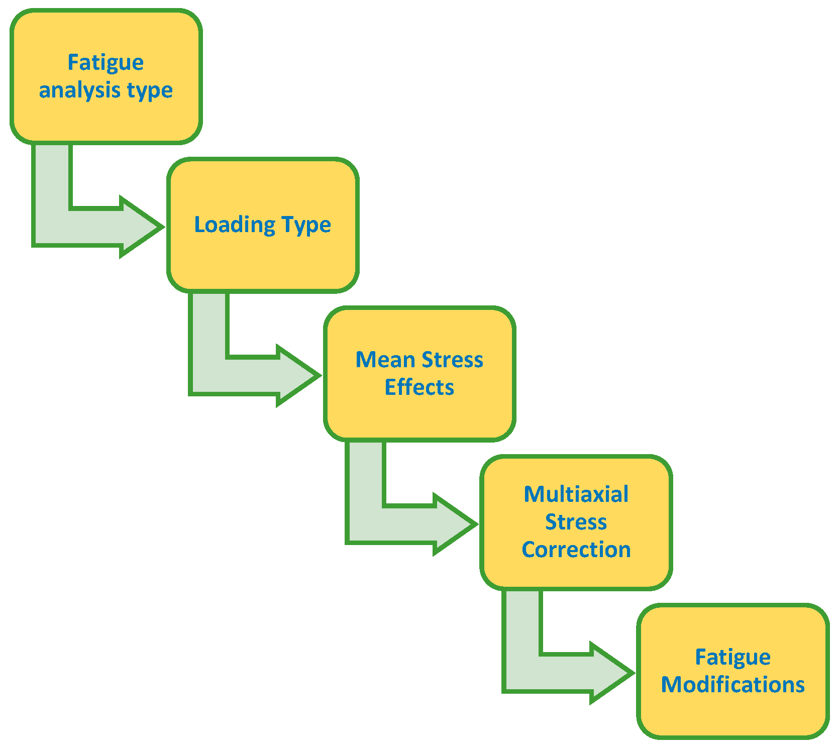
3.1. Fatigue Analysis Decisions

Numerical fatigue analysis can be divided into five common stages listed in Figure 3. This figure illustrates the general flow of decisions required to perform a fatigue analysis.
Fatigue analysis consists of ascertaining the stress life and strain life. Stress life is based on empirical S–N curves and then modified by a variety of factors. Strain life is based on the strain-life relation equation. The strain-life method is concerned with crack initiation and usually deals with relatively low cycles (less than 105 cycles). In this study, the stress-life method is used for life-cycle simulation of the railway sleeper. The stress-life method focuses on total fatigue life, which doesn’t distinguish between cracking initiation and progression. The stress-life method is also suitable for simulation of relatively high cycles (more than 105 cycles) [32]. Normally, railway sleepers experience millions of cyclic loads during service life.

3.2. Types of Cyclic Loading

There are four types of fatigue loading in the simulation:
  • Constant amplitude, proportional loading;
  • Constant amplitude, non-proportional loading;
  • Non-constant amplitude, proportional loading;
  • Non-constant amplitude, non-proportional loading.
Each passed wheel is assumed as a single cycle with constant amplitude. The principal stress axes do not change over time [32]. Therefore, constant amplitude with proportional loading is used for fatigue-life simulation of the railway sleeper. Figure 4 shows the types of loading used in the simulation.

3.3. Fatigue Life Results

In the fatigue analysis, the typical stress analysis can be used to determine the fatigue life of the prestressed concrete sleeper when it is subject to cyclic loads. This method is based on the S–N curve as part of the material definition of railway sleepers. The S–N curve is cyclic stress (S) against the logarithmic scale of cycles to failure (N). In the stress-life method, the alternating stress vs. the number of cycles to failure data are needed to put into the model [32]. It should be noted that the fatigue-life results using the stress-life method represent the available life for the given fatigue analysis without considering crack propagation and factors such as bond-slip, environmental conditions, etc.

4. Prestressed Concrete Sleeper Modelling

4.1. Properties of the Railway Sleeper

This project is a collaborative study between the University of Birmingham and the China Academy of Railway Sciences (CARS). CARS has commissioned full-scale experimental studies to support this collaboration. In this study, the 2600-mm long Chinese Type III prestressed concrete sleeper (Figure 5) was originally designed for high-speed railways, with the properties shown in Table 3. The dimension of the sleeper is approximately 2600 mm × 320 mm × 260 mm including 10 prestressing tendons with 7 mm diameters. The sleeper will be assessed using the numerical and theoretical approaches to calculate the life-cycle.

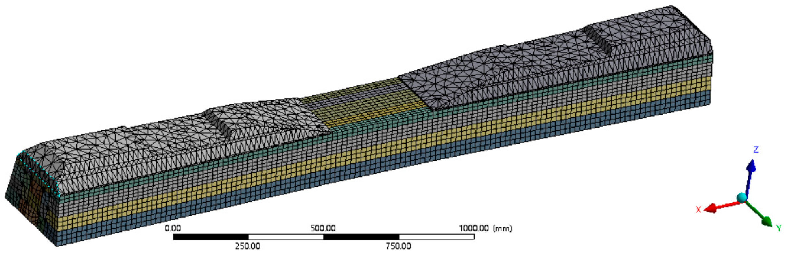
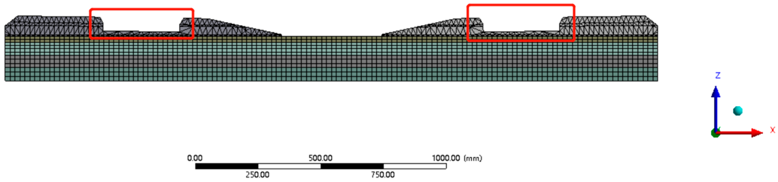
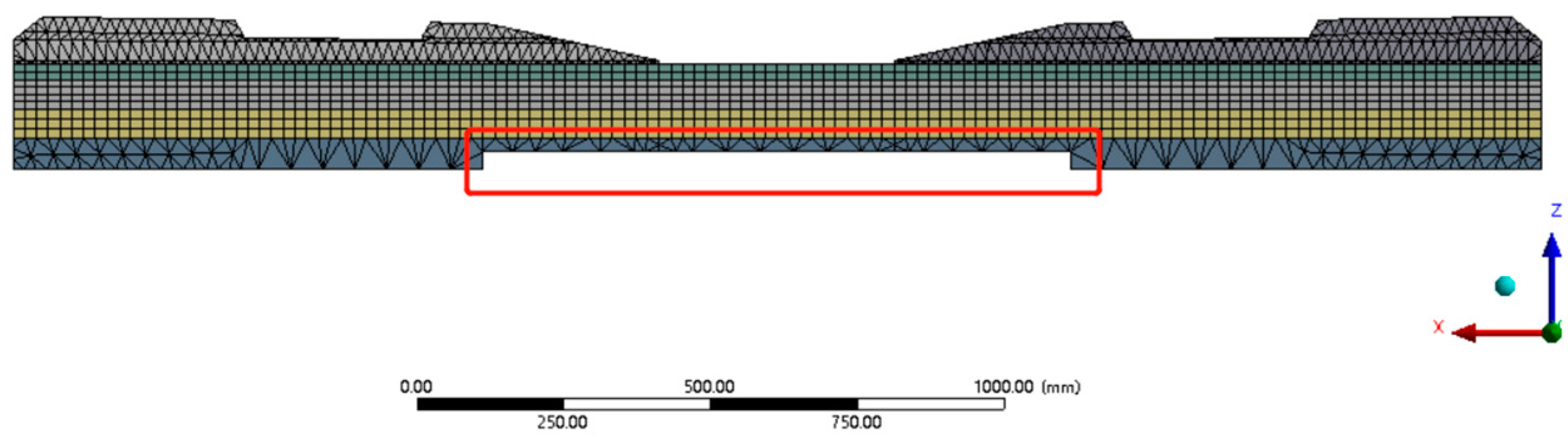
4.2. Finite Element Model

In this study, the finite element method (FEM) is used to analyze the life-cycle of prestressed concrete sleepers with surface abrasion. The prestressed concrete sleeper is modelled in ANSYS Workbench (shown in Figure 6). The finite element model is composed of concrete and prestressed tendons. The Solid65 element is used to model the concrete material. In the model, thermal condition is used to simulate the characteristics of prestressing tendons. The support condition is modelled as fixed support. In the model, the contact condition No Separation is used between concrete and prestressing tendons. Therefore, the concrete and prestressing tendons are considered as being well adhered, while the bond slip and bursting are ignored. The material properties of the FE sleeper model are shown in Table 3. The modelling is performed with the minimum difference from the real sleeper.

4.3. Experimental Program

The bending moment test at the midspan of the full-scale prestressed concrete sleeper using the digital image correlation method (DIC) conducted by Jing et al. [33], as part of CARS’s commissioned tests, is used for the FE model validation. This experiment presented the nonlinear structural performance of Chinese Type III prestressed concrete sleeper. The arrangement for the test follows EN13230-2 shown in Figure 7 [33]. The loading surface was placed at the bottom midspan of the sleeper with a resilient pad. Two rail pads were placed between the rail-seat area and each support. Sadeghi and Barati stated that the normal failure load of concrete sleepers is 140 kN [34], thus the applied load range was between 0 to 140 kN. The speed of loading was no more than 120 kN/min. The experimental load–deflection results in terms of the DIC will be compared with the numerical results for the sleeper model validation.

4.4. FE Sleeper Model Validation

The material and structural performance of the FE sleeper model needs to be validated for further simulation. Previous research has presented the validation of the FE sleeper model in reference [23]. The mesh study of the FE sleeper model is also carried out for the models with 20 mm, 30 mm, and 40 mm mesh size. Figure 8 illustrates the load–deflection responses of the experimental and numerical results. The mesh study shows slight differences between the mesh size 20 mm, 30 mm, and 40 mm. Therefore, the closest results of mesh size 30 mm are selected (with 5.99% max error calculated from the deviation of the experimental and FEM results). The numerical performance indicates a good agreement with the experimental results.

4.5. Fatigue Model Validation

The life-cycle is evaluated by numerical and theoretical approaches with the cyclic loads between 55 kN and 365 kN. Each cyclic load (constant) can only calculate one fatigue life for both the theoretical and numerical methods. These results present the available life of the prestressed concrete sleepers for the fatigue analysis. The cyclic load is applied at the rail-seat area shown in Figure 9. Note that the static and fatigue tests are in a different test set up. The negative bending test was performed for the static tests (in accordance with EN 13230), whilst the positive rail-seat tests were considered for the fatigue tests. The theoretical results of the life-cycle were according to the damage accumulation method. The calculation details were presented in reference [29]. The results of the numerical and theoretical calculation are demonstrated in Figure 10. Life cycles are inversely proportional with the constant cyclic loads for both the numerical and theoretical results. In comparison between numerical and theoretical results, the average error is only 13.03%.
The experiments conducted by Parvez and Foster investigated failure cycles of prestressed concrete sleepers under cyclic loads [16,36,37]. Two specimens were selected from their experiments in order to validate the numerical fatigue model. The average of the failure cycles of the specimens are calculated and presented in Table 4. Table 5 shows the comparison between the experimental, theoretical, and numerical results.
From Figure 10 and Table 5, it is seen that the numerical results have a good correlation with the experimental and theoretical results, which provides a reliable method for the life-cycle in the surface abrasion study.

5. Influence of Surface Abrasions on Fatigue Life

In reality, railway sleepers experience aggressive dynamic loading, especially in sharp curves and high gradients, which causes rail-seat abrasion. The ballast angularity also results in differential abrasion on the soffit abrasion. The most common surface abrasions of railway sleepers are the rail-seat abrasion, the soffit abrasion at rail-seat, and the soffit abrasion at midspan [10]. Figure 11 shows the typical abrasions of a railway sleeper. This section investigates the life-cycle of the railway sleeper with each typical surface abrasion pattern using the numerical fatigue-life model. In the simulation, abrasions are applied in the FE sleeper model by changing the geometry of the rail-seat area and bottom surface at midspan. It is clear that the life-cycle can be affected by the surface abrasions.

5.1. Rail-Seat Abrasion Results

Figure 12 shows the location of the rail-seat abrasion of the railway sleeper model. The depths of the rail-seat abrasions are chosen as 5 mm, 15 mm, and 30 mm to analyze the effect of the life-cycle on the railway sleeper. Loads of between 55 kN to 325 kN are applied in the simulation. Table 6 and Figure 13 indicate the results of the life-cycle with rail-seat abrasion.

5.2. Soffit Abrasion at Rail-Seat Results

Figure 14 shows the location of the soffit abrasion at the rail seat of the railway sleeper model. The depths of the soffit abrasions at the rail seat are chosen as 5 mm, 15 mm, and 30 mm to analyze the effect on the life-cycle of the railway sleeper. Loads of between 55 kN to 325 kN are applied in the simulation. Table 7 and Figure 15 indicate the results on the life-cycle with the soffit abrasion at the rail seat.

5.3. Soffit Abrasion at Midspan Results

Figure 16 shows the location of the soffit abrasion at the midspan of the railway sleeper model. The depths of the soffit abrasion at midspan are chosen as 5 mm, 15 mm, and 30 mm to analyze the effect on the life-cycle of the railway sleeper. Loads of between 55 kN to 325 kN are applied in the simulation. Table 8 and Figure 17 indicate the results on the life-cycle with the soffit abrasion at midspan.

5.4. Rail-Seat Abrasion and Soffit Abrasion at Rail Seat Results

Figure 18 shows the location of the rail-seat abrasion and the soffit abrasion at the rail seat of the railway sleeper model. The depths of the abrasions are chosen as 5 mm & 5 mm, 15 mm & 15 mm, and 30 mm & 30 mm to analyze the effect on the life-cycle of the railway sleeper. Loads of between 55 kN to 325 kN are applied in the simulation. Table 9 and Figure 19 indicate the results on the life-cycle with the rail-seat abrasion and soffit abrasion at the rail seat.

5.5. Rail-Seat Abrasion and Soffit Abrasion at Midspan Results

Figure 20 shows the location of the rail-seat abrasion and the soffit abrasion at midspan of the railway sleeper model. The depths of the abrasions are chosen as 5 mm & 5 mm, 15 mm & 15 mm, and 30 mm & 30 mm to analyze the effect on the life-cycle of the railway sleeper. Loads of between 55 kN to 325 kN are applied in the simulation. Table 10 and Figure 21 indicate the results on the life-cycle with the rail-seat abrasion and soffit abrasion at midspan.

5.6. Soffit Abrasion at Rail Seat and Soffit Abrasion at Midspan Results

Figure 22 shows the location of the soffit abrasion at the rail seat and the soffit abrasion at midspan of the railway sleeper model. The depths of the abrasions are chosen as 5 mm & 5 mm, 15 mm & 15 mm, and 30 mm & 30 mm to analyze the effect on the life-cycle of the railway sleeper. Loads of between 55 kN to 325 kN are applied in the simulation. Table 11 and Figure 23 indicate the results on the life-cycle with the soffit abrasion at the rail seat and the soffit abrasion at midspan.

5.7. Rail-Seat Abrasion, Soffit Abrasion at Rail Seat, and Soffit Abrasion at Midspan Results

Figure 24 shows the location of the rail-seat abrasion, the soffit abrasion at rail seat, and the soffit abrasion at midspan of the railway sleeper model. The depths of the abrasions are chosen as 5 mm & 5 mm & 5 mm, 15 mm & 15 mm & 15 mm, and 30 mm & 30 mm & 30 mm to analyze the effect on the life-cycle of the railway sleeper. Loads of between 55 kN to 325 kN are applied in the simulation. Table 12 and Figure 25 indicate the results on the life-cycle with the rail-seat abrasion, the soffit abrasion at rail seat, and the soffit abrasion at midspan.

5.8. Discussions

Section 5.1, Section 5.2 and Section 5.3 demonstrate the life-cycle results with the single abrasion pattern of the railway sleeper. Section 5.4, Section 5.5, Section 5.6 and Section 5.7 present the life-cycle results with the combination of the different abrasion patterns of the railway sleeper. The abrasion depth of the prestressed concrete sleeper is reduced by 5 mm, 15 mm, and 30 mm, respectively. In general, the life-cycle of the worn railway sleeper is less than an undamaged sleeper. The life-cycle decreases with an increase in abrasion, especially large depth abrasion (30 mm). Higher dynamic loads result in a reduction in the life-cycle. However, at the same abrasion depth, the performance of the sleeper varies with different abrasion patterns.
On comparison with each single abrasion patterns, the effect of the soffit abrasion at rail seat on the railway sleeper is the most significant. The soffit abrasion at midspan also has a very significant influence on the sleeper. For both of the soffit abrasion patterns, the life-cycle falls by more than 90%. The change of the life-cycle due to rail-seat abrasion is relatively low, with only a 53.32% change in comparison with an undamaged sleeper. However, when the rail-seat abrasion rises to 30 mm, the life-cycle also reduces by up to 93.63%.
Section 5.4, Section 5.5, Section 5.6 and Section 5.7 show that the combination of the different abrasion patterns affects the life-cycle of the prestressed concrete sleeper. The results demonstrate more than one abrasion pattern occurring in the sleeper, and the life-cycle decreases sharply. There are four groups of multi-abrasion patterns analyzed. The triple abrasion (combination of rail-seat abrasion, soffit abrasion at rail seat, and soffit abrasion at midspan) is the most critically damaging. With a 5 mm abrasion for each position, the life-cycle falls by 97.16%. The worst case in this study is the triple abrasion with 30 mm depth, where the life-cycle undergoes a 99.88% change. For the double abrasion patterns (rail-seat abrasion/soffit abrasion at rail seat, rail-seat abrasion/soffit abrasion at midspan, and soffit abrasion at rail seat/soffit abrasion at midspan), the results are not very different. The combination of soffit abrasion at rail seat and soffit abrasion at midspan pattern is relatively worse than the other two double abrasion patterns, which reduces the life-cycle by up to 96.16%.

6. Conclusions

In this research, 3D finite element models were developed to investigate the fatigue behavior of the prestressed concrete sleeper considering surface abrasion. The theoretical life-cycle assessment method based on the damage accumulation concept was also demonstrated. The fatigue behavior of the prestressed concrete sleepers with surface abrasions were assessed by a numerical fatigue model. Seven cases of surface abrasion pattern were considered in this study. For each case analysis, a series of abrasion depths and dynamic loads were applied in numerical model in order to investigate the performance of the prestressed concrete sleeper. Based on the obtained results of this study, the key findings are revealed as follows:
  • Surface abrasion significantly influences the structural performance of prestressed concrete sleepers. From the results, undamaged sleepers have much more service life than worn sleepers. Therefore, track maintenance should be carried out regularly to prevent loss of life-cycle from surface abrasion;
  • Rail-seat abrasion has a relatively low influence on railway sleepers in comparison with soffit abrasion. Soffit abrasion at the rail seat can critically reduce the life-cycle;
  • The risk of more than one abrasion pattern happening in the railway sleeper is far greater than a single abrasion pattern;
  • In this study, the life-cycle was found to largely depend on the magnitude of the dynamic load and abrasion depth. Both large dynamic loads and abrasion depths can result in serious decreases in life-cycle.
This study is the first to present a finite element modelling for determining the life-cycle of the prestressed concrete sleepers with surface abrasion. The numerical fatigue model was validated using the theoretical life-cycle assessment method. The FE sleeper model was also validated by comprehensive experimental data. It should be noted that, in general, the lifespan of prestressed concrete sleepers can also be affected by factors such as bond slip, environmental conditions, chemical attack, etc. For example, the bond between the strand and the concrete is a factor which can directly or indirectly influence the lifespan of prestressed concrete sleepers. Therefore, more factors affecting the fatigue life of prestressed concrete sleepers are suggested for investigation in future research.
This paper confirms that inspection of railway sleepers is essential and even small abrasions that occur in critical positions can still affect the performance of railway sleepers. It is obvious that surface abrasions can result in a significant reduction in the life-cycle. Hence, it is important to reduce the impact loading to prevent railway sleepers from failing. From this study, the railway concrete sleepers should be inspected regularly, for example, every 10 to 15 years (or around 300 to 450 MGT or million gross tons). The outcomes of this study lead to a better insight into the effects of surface abrasion on prestressed concrete sleepers. This insight will enhance the inspection criteria of railway sleepers and track maintenance.

Author Contributions

Conceptualization, D.L. and S.K.; methodology, D.L.; software, D.L.; validation, D.L., R.Y. and S.K.; formal analysis, D.L.; investigation, D.L. and R.Y.; resources, R.Y.; data curation, D.L.; writing—original draft preparation, D.L.; writing—review and editing, S.K.; visualization, D.L.; supervision, S.K.; project administration, S.K.; funding acquisition, S.K. All authors have read and agreed to the published version of the manuscript.

Funding

This research was funded by the European Commission, grant number: H2020-MSCA-RISE No. 691135.

Institutional Review Board Statement

Not applicable.

Informed Consent Statement

Not applicable.

Data Availability Statement

The data that support the findings of this study are available from the corresponding author upon reasonable request.

Acknowledgments

The authors are grateful to the Track Engineering and Operations for Future Uncertainties (TOFU) Lab, University of Birmingham, for support throughout this study. The authors would like to thank the Commission for H2020-MSCA-RISE, Project No. 691135 “RISEN: Rail Infrastructure Systems Engineering Network” [38]. In addition, the authors wish to thank the China Railway (No K2021G015) and China Academy of Railway Sciences Corporation Limited (No 2020YJ031) for the experimental programs. The first author would like to thank the East China Architectural Design & Research Institute (ECADI) for technical support.

Conflicts of Interest

The authors declare no conflict of interest.

References

  1. Steffens, D.M. Identification and Development of a Model of Railway Track Dynamic Behaviour. Ph.D. Thesis, Queensland University of Technology, Brisbane City, QLD, Australia, 2005. [Google Scholar]
  2. Taherinezhad, J.; Sofi, M.; Mendis, P.; Ngo, T. A review of behaviour of prestressed concrete sleepers. Electron. J. Struct. Eng. 2013, 13, 1–16. [Google Scholar] [CrossRef]
  3. Esveld, C.; Esveld, C. Modern Railway Track; MRT-Productions: Zaltbommel, The Netherland, 2001; Volume 385. [Google Scholar]
  4. Kaewunruen, S.; Remennikov, A.M. Impact capacity of railway prestressed concrete sleepers. Eng. Fail. Anal. 2009, 16, 1520–1532. [Google Scholar] [CrossRef]
  5. Remennikov, A.; Murray, M.H.; Kaewunruen, S. Reliability-based conversion of a structural design code for railway prestressed concrete sleepers. Proc. Inst. Mech. Eng. Part F J. Rail Rapid Transit 2012, 226, 155–173. [Google Scholar] [CrossRef]
  6. Van Dyk, B.J.; Dersch, M.S.; Edwards, J. International Concrete Crosstie and Fastening System Survey–Final Results; University of Illinois at Urbana-Champaign: Champaign, IL, USA, 2012. [Google Scholar]
  7. Ferdous, W.; Manalo, A. Failures of mainline railway sleepers and suggested remedies–review of current practice. Eng. Fail. Anal. 2014, 44, 17–35. [Google Scholar] [CrossRef]
  8. Van Dyk, B.J.; Edwards, J.R.; Dersch, M.S.; Ruppert, C.J., Jr.; Barkan, C.P. Evaluation of dynamic and impact wheel load factors and their application in design processes. Proc. Inst. Mech. Eng. Part F J. Rail Rapid Transit 2017, 231, 33–43. [Google Scholar] [CrossRef]
  9. Remennikov, A.M.; Kaewunruen, S. A review of loading conditions for railway track structures due to train and track vertical interaction. Struct. Control Health Monit. Off. J. Int. Assoc. Struct. Control Monit. Eur. Assoc. Control Struct. 2008, 15, 207–234. [Google Scholar] [CrossRef]
  10. Li, D.; You, R.; Kaewunruen, S. Mechanisms and Evolution of Cracks in Prestressed Concrete Sleepers Exposed to Time-Dependent Actions. Appl. Sci. 2022, 12, 5511. [Google Scholar] [CrossRef]
  11. Remennikov, A.; Kaewunruen, S. Determination of dynamic properties of rail pads using an instrumented hammer impact technique. Acoust. Aust. 2005, 33, 63–67. [Google Scholar]
  12. Kaewunruen, S.; Remennikov, A. On the residual energy toughness of prestressed concrete sleepers in railway track structures subjected to repeated impact loads. Electron. J. Struct. Eng. 2013, 13, 41–61. [Google Scholar] [CrossRef]
  13. Kaewunruen, S.; Remennikov, A.M.; Murray, M.H. Introducing a new limit states design concept to railway concrete sleepers: An Australian experience. Front. Mater. 2014, 1, 8. [Google Scholar] [CrossRef]
  14. Chen, Z.; Shin, M.; Wei, S.; Andrawes, B.; Kuchma, D.A. Finite element modeling and validation of the fastening systems and concrete sleepers used in North America. Proc. Inst. Mech. Eng. Part F J. Rail Rapid Transit 2014, 228, 590–602. [Google Scholar] [CrossRef]
  15. César Bastos, J.; Dersch, M.S.; Edwards, J.R. Degradation Mechanisms of Concrete Due to Water Flow in Cracks of Prestressed Railroad Sleepers under Cyclic Loading. J. Mater. Civ. Eng. 2022, 34, 04022025. [Google Scholar] [CrossRef]
  16. Parvez, A.; Foster, S.J. Fatigue of steel-fibre-reinforced concrete prestressed railway sleepers. Eng. Struct. 2017, 141, 241–250. [Google Scholar] [CrossRef]
  17. Riding, K.A.; Peterman, R.J.; Guthrie, W.S.; Brueseke, M.; Mosavi, H.; Daily, K. A Study of Environmental and Track Factors That Contribute to Abrasion Damage of Concrete Ties; Department of Transportation, Federal Railroad Administration: Washington, DC, USA, 2019.
  18. Kernes, R.G.; Shurpali, A.A.; Edwards, J.R.; Dersch, M.S.; Lange, D.A.; Barkan, C.P. Investigation of the mechanics of rail seat deterioration and methods to improve the abrasion resistance of concrete sleeper rail seats. Proc. Inst. Mech. Eng. Part F J. Rail Rapid Transit 2014, 228, 581–589. [Google Scholar] [CrossRef]
  19. Ngamkhanong, C.; Li, D.; Remennikov, A.M.; Kaewunruen, S. Dynamic capacity reduction of railway prestressed concrete sleepers due to surface abrasions considering the effects of strain rate and prestressing losses. Int. J. Struct. Stab. Dyn. 2019, 19, 1940001. [Google Scholar] [CrossRef]
  20. Kaewunruen, S.; Ngamkhanong, C.; Lim, C.H. Damage and failure modes of railway prestressed concrete sleepers with holes/web openings subject to impact loading conditions. Eng. Struct. 2018, 176, 840–848. [Google Scholar] [CrossRef]
  21. You, R.; Goto, K.; Ngamkhanong, C.; Kaewunruen, S. Nonlinear finite element analysis for structural capacity of railway prestressed concrete sleepers with rail seat abrasion. Eng. Fail. Anal. 2019, 95, 47–65. [Google Scholar] [CrossRef]
  22. Li, D.; Ngamkhanong, C.; Kaewunruen, S. Influence of surface abrasion on creep and shrinkage of railway prestressed concrete sleepers. In IOP Conference Series: Materials Science and Engineering; IOP Publishing: Bristol, UK, 2017. [Google Scholar]
  23. Li, D.; Kaewunruen, S.; You, R. Time-dependent behaviours of railway prestressed concrete sleepers in a track system. Eng. Fail. Anal. 2021, 127, 105500. [Google Scholar] [CrossRef]
  24. EN 1992-1-1; Eurocode 2: Design of Concrete Structures—Part 1-1: General Rules and Rules for Buildings. European Union: Maastricht, The Netherlands, 2004.
  25. Nussbaumer, A. EN1993-1-9: A code for fatigue design. In Proceedings of the Conference Fatigue Design, Denver, CO, USA, 17–21 July 2005. [Google Scholar]
  26. Rao, V.; Talukdar, S. Prediction of fatigue life of a continuous bridge girder based on vehicle induced stress history. Shock Vib. 2003, 10, 325–338. [Google Scholar] [CrossRef]
  27. Kaewunruen, S. Monitoring structural deterioration of railway turnout systems via dynamic wheel/rail interaction. Case Stud. Nondestruct. Test. Eval. 2014, 1, 19–24. [Google Scholar] [CrossRef]
  28. Nielsen, J.C.; Li, X. Railway track geometry degradation due to differential settlement of ballast/subgrade–numerical prediction by an iterative procedure. J. Sound Vib. 2018, 412, 441–456. [Google Scholar] [CrossRef]
  29. You, R.; Li, D.; Ngamkhanong, C.; Janeliukstis, R.; Kaewunruen, S. Fatigue life assessment method for prestressed concrete sleepers. Front. Built Environ. 2017, 3, 68. [Google Scholar] [CrossRef]
  30. You, R.; Kaewunruen, S. Evaluation of remaining fatigue life of concrete sleeper based on field loading conditions. Eng. Fail. Anal. 2019, 105, 70–86. [Google Scholar] [CrossRef]
  31. Béton, C.E.-I.d. CEB-FIP Model Code 1990: Design Code; Thomas Telford Publishing: London, UK, 1993. [Google Scholar]
  32. Browell, R.; Hancq, A. Calculating and Displaying Fatigue Results; Ansys Inc.: Canonsburg, PA, USA, 2006; p. 2. [Google Scholar]
  33. EN 13230-2; Railway Applications-Track-Concrete Sleepers and Bearers Part 2: Prestressed Monoblock Sleepers. Standardization, E.C.f., 2009. Available online: https://standards.iteh.ai/catalog/standards/cen/afc7f289-4b2c-4620-9849-1b5e6a7b865b/en-13230-2-2016 (accessed on 2 August 2022).
  34. Sadeghi, J.; Barati, P. Comparisons of the mechanical properties of timber, steel and concrete sleepers. Struct. Infrastruct. Eng. 2012, 8, 1151–1159. [Google Scholar] [CrossRef]
  35. Jing, G.; Yunchang, D.; You, R.; Siahkouhi, M. Comparison study of crack propagation in rubberized and conventional prestressed concrete sleepers using digital image correlation. Proc. Inst. Mech. Eng. Part F J. Rail Rapid Transit 2022, 236, 350–361. [Google Scholar] [CrossRef]
  36. Parvez, A.; Foster, S.J. Fatigue behavior of steel-fiber-reinforced concrete beams. J. Struct. Eng. 2015, 141, 04014117. [Google Scholar] [CrossRef]
  37. Li, D.; Kaewunruen, S.; You, R.; Liu, P. Fatigue life modelling of railway prestressed concrete sleepers. Structures 2022, 41, 643–656. [Google Scholar] [CrossRef]
  38. Kaewunruen, S.; Sussman, J.M.; Matsumoto, A. Grand challenges in transportation and transit systems. Front. Built Environ. 2016, 2, 4. [Google Scholar] [CrossRef] [Green Version]
Figure 1. S–N curve for concrete [31].
Sustainability 14 11237 g001
Figure 2. S–N curve for prestressing tendons [31].
Sustainability 14 11237 g002
Figure 3. Flowchart for fatigue analysis decision tree.
Sustainability 14 11237 g003
Figure 4. Cyclic loading type for life-cycle simulation of the railway sleeper.
Sustainability 14 11237 g004
Figure 5. Chinese Type III prestressed concrete sleeper.
Sustainability 14 11237 g005aSustainability 14 11237 g005b
Figure 6. FE sleeper model.
Sustainability 14 11237 g006
Figure 7. Arrangement for the bending moment test at midspan of the prestressed concrete sleeper [33,35]. (a) Experimental apparatus of the bending moment test. (b) Setup for the bending moment test.
Sustainability 14 11237 g007
Figure 8. Load–deflection responses of experimental and numerical results.
Sustainability 14 11237 g008
Figure 9. Setup for boundary conditions in the fatigue life simulation. The sleepers in the model are fully supported by ballast and substructure.
Sustainability 14 11237 g009
Figure 10. Comparison between numerical and theoretical fatigue-life results.
Sustainability 14 11237 g010
Figure 11. Typical surface abrasions of railway sleepers [10].
Sustainability 14 11237 g011
Figure 12. Rail-seat abrasion of the railway sleeper model.
Sustainability 14 11237 g012
Figure 13. Comparison of life-cycle results with rail-seat abrasion.
Sustainability 14 11237 g013
Figure 14. Soffit abrasion at rail seat of the railway sleeper model.
Sustainability 14 11237 g014
Figure 15. Comparison of life-cycle results with soffit abrasion at rail seat.
Sustainability 14 11237 g015
Figure 16. Soffit abrasion at midspan of the railway sleeper model.
Sustainability 14 11237 g016
Figure 17. Comparison of life-cycle results with soffit abrasion at midspan.
Sustainability 14 11237 g017
Figure 18. Rail-seat abrasion and soffit abrasion at rail seat of the railway sleeper model.
Sustainability 14 11237 g018
Figure 19. Comparison of life-cycle results with rail-seat abrasion and soffit abrasion at rail seat.
Sustainability 14 11237 g019
Figure 20. Rail-seat abrasion and soffit abrasion at midspan of the railway sleeper model.
Sustainability 14 11237 g020
Figure 21. Comparison of life-cycle results with rail-seat abrasion and soffit abrasion at midspan.
Sustainability 14 11237 g021
Figure 22. Soffit abrasion at rail seat and soffit abrasion at midspan of the railway sleeper model.
Sustainability 14 11237 g022
Figure 23. Comparison of life-cycle results with soffit abrasion at rail seat and soffit abrasion at midspan.
Sustainability 14 11237 g023
Figure 24. Rail-seat abrasion, soffit abrasion at rail seat and soffit abrasion at midspan of the railway sleeper model.
Sustainability 14 11237 g024
Figure 25. Comparison of life-cycle results with rail-seat abrasion, soffit abrasion at rail seat and soffit abrasion at midspan.
Sustainability 14 11237 g025
Table 1. Most common causes of concrete sleeper failures [6].
Main CausesProblemsWorldwide Response 1
Lateral load
  • Abrasion on rail-seat
3.15
  • Shoulder/fastening system wear or fatigue
5.5
Vertical dynamic load
  • Cracking from dynamic loads
5.21
  • Derailment damage
4.57
  • Cracking from center binding
5.36
Manufacturing and maintenance defects
  • Tamping damage
6.14
  • Others (e.g., manufactured defects)
4.09
Environmental considerations
  • Cracking from environmental or chemical degradation
4.67
1 Ranked from 1 to 8, with 8 being the most critical.
Table 2. Parameters of S–N curve for prestressing steel [31].
S–N Curve of Prestressing Steel Used forStress Exponent Δ σ N at   N Cycles   ( MPa )
N k 1 k 2
Pre-Tensioning10659185
Table 3. Material properties of Chinese Type III prestressed concrete sleeper.
Material PropertiesBasic VariablesValue
Concrete
  • Mean compressive strength
65 MPa
  • Modulus of elasticity
33 GPa
  • Yield strength
1570 MPa
Prestressed wire
  • Modulus of elasticity
200 GPa
  • Prestressing force
420 kN
Table 4. Experimental failure cycle of prestressed concrete sleepers [29].
Specimen IDFailure CyclesAverageStandard Deviation
SF2-a773,793896,290173,236
SF3-a1,018,787
Table 5. Comparison between experimental, theoretical, and numerical results.
Failure Cycles
Experimental ResultTheoretical ResultDeviation Ratio%Numerical ResultDeviation Ratio%
896,290889,5770.75849,0005.28
Table 6. Life-cycle results of the railway sleeper with rail-seat abrasion.
Load (kN)No Abrasion5 mm Rail-Seat Abrasion15 mm Rail-Seat Abrasion30 mm Rail-Seat Abrasion
553.47 × 10102.12 × 10101.75 × 10104.15 × 109
1058.79 × 1083.27 × 1082.23 × 1081.83 × 107
1602.39 × 1079.68 × 1066.81 × 1061.01 × 106
2152.30 × 1061.25 × 1069.90 × 1051.23 × 105
2706.79 × 1052.38 × 1051.82 × 10536,627
3251.52 × 10578,52162,59314,068
Table 7. Life-cycle results of the railway sleeper with soffit abrasion at rail seat.
Load (kN)No Abrasion5 mm Soffit Abrasion at Rail Seat15 mm Soffit Abrasion at Rail Seat30 mm Soffit Abrasion at Rail Seat
553.47 × 10102.85 × 1091.08 × 1095.04 × 108
1058.79 × 1081.10 × 1072.99 × 1061.63 × 106
1602.39 × 1077.19 × 1051.87 × 1051.02 × 105
2152.30 × 10685,37236,81622,380
2706.79 × 10526,46611,4134527
3251.52 × 10510,1651673936
Table 8. Life-cycle results of the railway sleeper with soffit abrasion at midspan.
Load (kN)No Abrasion5 mm Soffit Abrasion at Midspan15 mm Soffit Abrasion at Midspan30 mm Soffit Abrasion at Midspan
553.47 × 10104.59 × 1093.04 × 1091.54 × 109
1058.79 × 1082.09 × 1071.20 × 1074.81 × 106
1602.39 × 1071.10 × 1067.61 × 1052.68 × 105
2152.30 × 1061.37 × 10590,16850,015
2706.79 × 10539,96327,95315,505
3251.52 × 10515,34910,7363250
Table 9. Life-cycle results of the railway sleeper with rail-seat abrasion and soffit abrasion at rail seat.
Load (kN)No Abrasion5 mm & 5 mm15 mm & 15 mm30 mm & 30 mm
553.47 × 10102.25 × 1093.12 × 1083.25 × 107
1058.79 × 1088.01 × 1061.22 × 1061.90 × 105
1602.39 × 1075.80 × 10576,39120,139
2152.30 × 10669,48516,8781728
2706.79 × 10521,5412455792
3251.52 × 1056630871621
Table 10. Life-cycle results of the railway sleeper with rail-seat abrasion and soffit abrasion at midspan.
Load (kN)No Abrasion5 mm & 5 mm15 mm & 15 mm30 mm & 30 mm
553.47 × 10102.73 × 1091.33 × 1097.74 × 108
1058.79 × 1081.04 × 1073.95 × 1062.12 × 106
1602.39 × 1076.91 × 1052.31 × 1051.39 × 105
2152.30 × 10682,24844,03228,812
2706.79 × 10525,49813,6507828
3251.52 × 10595572466998
Table 11. Life-cycle results of the railway sleeper with soffit abrasion at rail seat and soffit abrasion at midspan.
Load (kN)No Abrasion5 mm & 5 mm15 mm & 15 mm30 mm & 30 mm
553.47 × 10102.49 × 1096.26 × 1083.37 × 108
1058.79 × 1089.23 × 1061.86 × 1061.28 × 106
1602.39 × 1076.38 × 1051.19 × 10579,896
2152.30 × 10676,11325,41517,652
2706.79 × 10523,59659632706
3251.52 × 1058078966881
Table 12. Life-cycle results of the railway sleeper with rail-seat abrasion, soffit abrasion at rail seat and soffit abrasion at midspan.
Load (kN)No Abrasion5 mm & 5 mm & 5 mm15 mm & 15 mm & 15 mm30 mm & 30 mm & 30 mm
553.47 × 10102.49 × 1096.26 × 1083.37 × 108
1058.79 × 1089.23 × 1061.86 × 1061.28 × 106
1602.39 × 1076.38 × 1051.19 × 10579,896
2152.30 × 10676,11325,41517,652
2706.79 × 10523,59659632706
3251.52 × 1058078966881
Publisher’s Note: MDPI stays neutral with regard to jurisdictional claims in published maps and institutional affiliations.

