Article

Research on Dynamic Characteristics of Joint of RC Frame Structure with NES

1
Department of Civil Engineering, Northeast Forestry University, Harbin 150040, China
2
Department of Civil Engineering, Qingdao Agricultural University, Qingdao 266109, China
*
Author to whom correspondence should be addressed.
Sustainability 2022, 14(18), 11229; https://doi.org/10.3390/su141811229
Submission received: 2 August 2022 / Revised: 23 August 2022 / Accepted: 5 September 2022 / Published: 7 September 2022

Abstract

:
The NES (nonlinear energy sink) is a new type of nonlinear tuned mass damper that is connected to the shock-absorbing main structure through strong nonlinear stiffness and viscous damping. The vibrational energy in the main structure is transferred to the NES oscillator by means of target energy transfer. A shaking table test of a 1:4 scaled RC (Reinforced Concrete) frame structure model with a new type of NES shock absorber was conducted to study the damping effect of the NES shock absorber, especially for the influence of joint strength and deformation. The NES used in this experiment has a relatively large nonlinear stiffness and a wide vibration absorption frequency band. The variation of reinforcement strains, node failure mode, and structural natural frequency of 1 story and two-layer joints of the model frame structure with NES were studied. The test results showed that NES could effectively reduce the strains of longitudinal reinforcement and stirrup in beams and columns and delay the plastic hinge development at the bottom and the top of the column. The frame model with NES installed has failures at the beam ends and shear failures at the nodes, realizing the seismic mechanism of solid columns and weak beams. Compared with ordinary seismic structures, the NES can effectively reduce the shear stress of concrete at the joints and alleviate the shear failure of joints. The final failure of the NES shock absorbing structure was the yielding of the steel bars at the bottom of the column and the crushing of the concrete at the foot of the column, and the connection between the column foot and the backplane became loose simultaneously. The decreasing rate of the vibration frequency declined due to the NES with varied broadband absorbing capability. It can be seen that the NES shock absorber not only has a good effect on reducing the seismic response of the structure, but more importantly, the damage of the structural nodes is greatly reduced, and therefore, the seismic capacity of the structure improved.

1. Introduction

The seismic damage to the RC frame structure is mostly concentrated in the joint areas in previous earthquakes [1]. The joints of reinforced concrete frame structure (RC frame) are the critical part of the structural force transmission, which are usually subject to tension and compression, shear force, and bending loads simultaneously; the stress situation of joints is complex [2]. Many researchers have studied the RC frame joints’ failure mode and transmission mechanism in recent years [3,4,5]. Fu proposed the force transfer mechanism of the joints and the influence of axial pressure on the seismic behavior of joints [6]. Chen put forward the design and calculation method of failure mode differentiation parameters on joints [7]. Fan tested the seismic behavior of reinforced concrete joints and developed the dynamic mechanical properties of joints under different axial compression ratios [8].
NES (nonlinear energy sink) is a new type of nonlinear tuned mass damper with strong nonlinear stiffness and viscous damping, which works with a broadband absorbing capability according to nonlinear vibrators. By means of target energy transfer, the seismic vibrational energy is transferred from the main structure to the NES oscillator. As a new passive damping device, NES has many advantages: easier to use, higher efficiency, stronger robustness, faster shock absorption than most traditional damping systems, and high application value [9,10].
Starosvetsky researched the optimization of NES parameters, and the test proved that the vibration control effect of NES was better than that of the tuned mass dampers (TMD) in the experiment [11]. Zhang et al. proposed a method to design the cubic stiffness of target energy transfer [12]. Finally, Liu studied the broadband control characteristics of NES by the shaking table test. Wang proposed an asymmetric nonlinear energy well and added an asymmetric NES to a scaled 3-layer steel frame structure for experiments. The results show that the asymmetric NES has superior control performance and has both frequency robustness and energy robustness. It also has a better control effect when the input energy and the frequency of the main structure are changed [13]. Wang proposed the single-sided vibro-impact track nonlinear energy sink (SSVI Track NES), and investigated the vibration reduction performance when the stiffness and damping of the SSVI track NES device changed simultaneously. The results show that the SSVI track NES can effectively reduce the structural response and has good NES stiffness and damping robustness at the same time [14]. Li studied the vibration suppression effect of the nonlinear energy well when the ship equipment was disturbed by the external shock excitation. The research results show that the nonlinear energy well has the advantages of absorbing and dissipating the external shock energy in a wide frequency range and has better robustness. It can quickly stabilize the ship equipment disturbed by shock excitation [15]. Yao analyzed the relationship between the vibration suppression performance of the energy trap and the excitation intensity based on energy dissipation. The results show that the internal mechanism of the target energy transfer is resonance capture. Only when the external excitation intensity reaches the trigger threshold is the target energy transfer excited, and the linear energy well effectively suppresses vibration [16]. Wang conducted an experimental inspection of a 2-DOF model building with an orbital NES attached. The track NES was shown to rapidly attenuate both impulsive and seismic responses. The results experimentally validate the analytical and numerical models of the track NES [17]. Wang proposed the optimal mass design of nonlinear energy sinks, revealed the relationship between damping and the optimal mass of NES, and discovered the advantages of the large-scale design of bistable nonlinear energy sinks [18]. Dekemele presented a novel nonlinear energy sink (NES) design with cubic stiffness, presenting a general method for optimizing randomly excited structural systems equipped with nonlinear energy sinks (NES) [19]. Zang proposed a generalized transmissibility for vibration absorption systems and compared two evaluation methods based on energetics and transmissibility, which provided a basis for the design and parameter optimization of NES absorbers [20]. Bab studied the performance of smooth nonlinear energy sink (NES) in reducing vibration of rotating beam under external force and compared the efficiency of optimal linear damper and optimal NES in vibration reduction of rotating beam. The results show that the optimal range of NES parameters is the range where SMR and weak modulation responses occur simultaneously [21]. Li proposed the shock mode and applied it to study the system with one-sided vibration shock nonlinear energy sink, revealed the energy transfer mechanism of the single-sided vibro-impact (SSVI) NES, discussed the influence of parameters on the performance of the NES, and obtained the satisfactory region of the SSVI NES design [22]. Qiu studied the design criteria of a tuned vibration shock (VI) nonlinear energy sink (NES) to control vibration under periodic and transient excitations. The results show that the design criteria not only predict the effective target energy transfer at resonant frequencies, but also the optimum performance can also be achieved over a range of frequencies [23]. Zhang studied thermal shock-induced vibration suppression of axially moving beams with nonlinear energy sinks (NESs), using a numerical algorithm to obtain the displacement responses of beams with and without NESs under thermal shock for different positions NES efficiency. The results show that NES can absorb a large amount of vibrational energy [24]. Guo studied adaptive and passive galloping suppression of suspended linear cables, explored the analytical mechanism of LCO, and emphasized the effects of NES mass ratio, damping, stiffness, and position on vibration suppression [25]. Boroson studied an NES probabilistic design approach that takes into account random designs, random variables and response discontinuities. To maximize the average efficiency, the algorithm is based on the identification of design regions and random spaces that correspond to significantly different NES efficiencies [26]. Zhang studied the nonlinear vibration absorption of laminated composite beams and used nonlinear energy sink (NES) vibration absorbers to control the lateral vibration of composite beams; within a certain range of NES parameters, different control effects were determined by approximate analysis. The results show that NES is an effective method to control the vibration of laminated composite beams in complex environments [27]. Geng proposes a packaged nonlinear energy sink with viscous and elastic limits, along with a multi-objective optimization strategy to control multimodal resonances. Then the continuous nonlinear model is analyzed approximately analytically and simulated numerically. Moreover, the E-NES parameters are optimized by the differential evolution algorithm. The results show that the packaged nonlinear energy sink is proven to suppress dual-resonant modes [28]. Jin proposed an unconventional nonlinear energy sink (NES) and performed multi-objective optimization, comparing the best performance of the proposed unconventional NES with that of an optimally tuned unconventional TMD. It was found that the proposed non-traditional variant NES exhibits typical NES characteristics [29]. Qiu designed a new nonlinear energy sink with variable pitch springs, introduced a general model of nonlinear energy sink systems that provide pure cubic stiffness nonlinearity, and studied the force–displacement relationship of the entire system embedded on an electrodynamic shaker identification and experimentation. The results show that this nonlinear energy sink can not only output the anticipated nonlinearity, but can also produce energy pumping to protect the primary system in a large band of frequencies, thus making it practical for the application of passive vibration control [30]. Chen proposed multimode resonances elimination of composite plates by an inertial nonlinear energy sink (NES). It shows the benefits of the inertial NES without affecting the resonant frequency of the primary system. By comparing the resonance with and without the NES, the proposed device is certified that it has good efficiency in vibration eliminating for both low-order and high-order resonance [31]. Chen proposed a non-smooth NES with decreasing stiffness, which decreases as its magnitude exceeds the initial range, with the help of a Runge–Kutta-based procedure to analyze the dynamic behavior of the system using a least-squares-based procedure. The results show that the non-smooth NES can eliminate stable higher branches, thus expanding the effective excitation range until the excitation amplitude increases to a very high level [32]. Using an event-driven approach based on an explicit variable-step integration scheme, Fang presented the effects of mass ratio and gap on resonance energy scattering, and conducted optimization studies on single and multiple VI NES systems, finally giving a variety of the advantages of different VI NES in terms of vibration reduction [33]. Zang proposed a novel nonlinear energy sink that reduces the mass of the device through the introduction of levers. The lever-type nonlinear energy sink is attached to a two-degree-of-freedom simplified model of whole-spacecraft subjected a harmonic excitation. The harmonic balance method with an alternating frequency time was applied to predict the variation of the transmissibility with the excitation frequency. The results show that the lever-type nonlinear energy sink outperforms the traditional nonlinear energy sink with the same mass, damping and nonlinear stiffness [34]. Tan designed a light-weight broadband isolator and built a complete mathematical model of the ring with nonlinear energy sinks, resulting in two coupled nonlinear partial differential equations (PDEs) with closed boundary conditions. In addition, the effects of mass, nonlinear stiffness and damping ratio were examined, and it was found that the nonlinear energy sink in the annular isolator outperformed the conventional linear sink with the same mass, damping and stiffness [35]. Dekemele investigated the effect of different nonlinearities on the targeted energy transfer, and the resonance capture cascading performance was investigated. Actual numerical simulations presented in the study validate the merit of both the pumping time and cascading time [36]. Li studied a linear oscillator (LO) coupled with two vibro-impact (VI) nonlinear energy sinks (NES) in parallel under periodic and transient excitations, respectively. Different basic response regimes were experimentally observed and applied to explain complicated nonlinear dynamics resulting from VI. Nonlinear targeted energy transfer was experimentally found to be relatively optimal for the response regime with two impacts per cycle, whether under periodic or transient excitations [37]. Wierschem installed a nonlinear energy sink on a nine-story steel frame structure and analyzed the shock absorption performance of NES under the background of biased explosion loads. Six NESs were arranged on the steel frame, and two NESs had vibration shock nonlinearity. The other four have smooth but inherently nonlinear stiffness. The results demonstrate that the proposed passive nonlinear mitigation system can quickly and effectively damp the overall structural response, thereby minimizing the peak response to the structure [38]. Yang proposed a nonlinear energy sink (NES) method for whole-spacecraft vibration reduction. The NES attachment hardly changes the natural frequencies of the structure. The experimental transmissibility results demonstrate the significant reduction of the whole-spacecraft structure vibration over a broad spectrum of excitation frequency [39]. Dai comprehensively and elaborately investigated the VIV amplitude of the cylinder suppressed by a NES and explored the transfer mechanism of lock-in region due to the present of NES. At the same time, the efficient NES parameters were designed for alleviating VIV responses [40]. Yang proposed a new representation of transmissibility based on nonlinear output frequency-response functions (NOFRFs) and applied it to evaluate the vibration isolation performance of nonlinear energy sink in the frequency domain, using a two-degree-of-freedom system with an NES additional system. A 2-DOF structure was numerically simulated, and the results showed that the transmissibility of the 2-DOF structure with NES was reduced in all resonance regions [41]. The results showed that NES could play a good role in the vibration control of structures [42].
In summary, the above research studies mostly focused on the cubic stiffness, damping and robust performance of NES. Few studies have been conducted on the shock absorption effect of NES on large-mass structures, and even less on the impact of NES on the failure mode of structural joints, which is the key factor to determine the seismic resistance performance of RC frame structures. This paper focused on the study of the effect of broadband NES shock absorbers on the seismic failure mode of RC frame structure joints with high stiffness and studied the seismic performance of NES shock absorber structures from different observation angles. Therefore, the shaking table test of an RC scale model-frame structure with NES was carried out. Then the natural frequencies, failure modes, and strains of RC frame structures under earthquake were analyzed, and the effect of NES on the seismic performance of RC frame joints was determined.

2. Experimental Setup

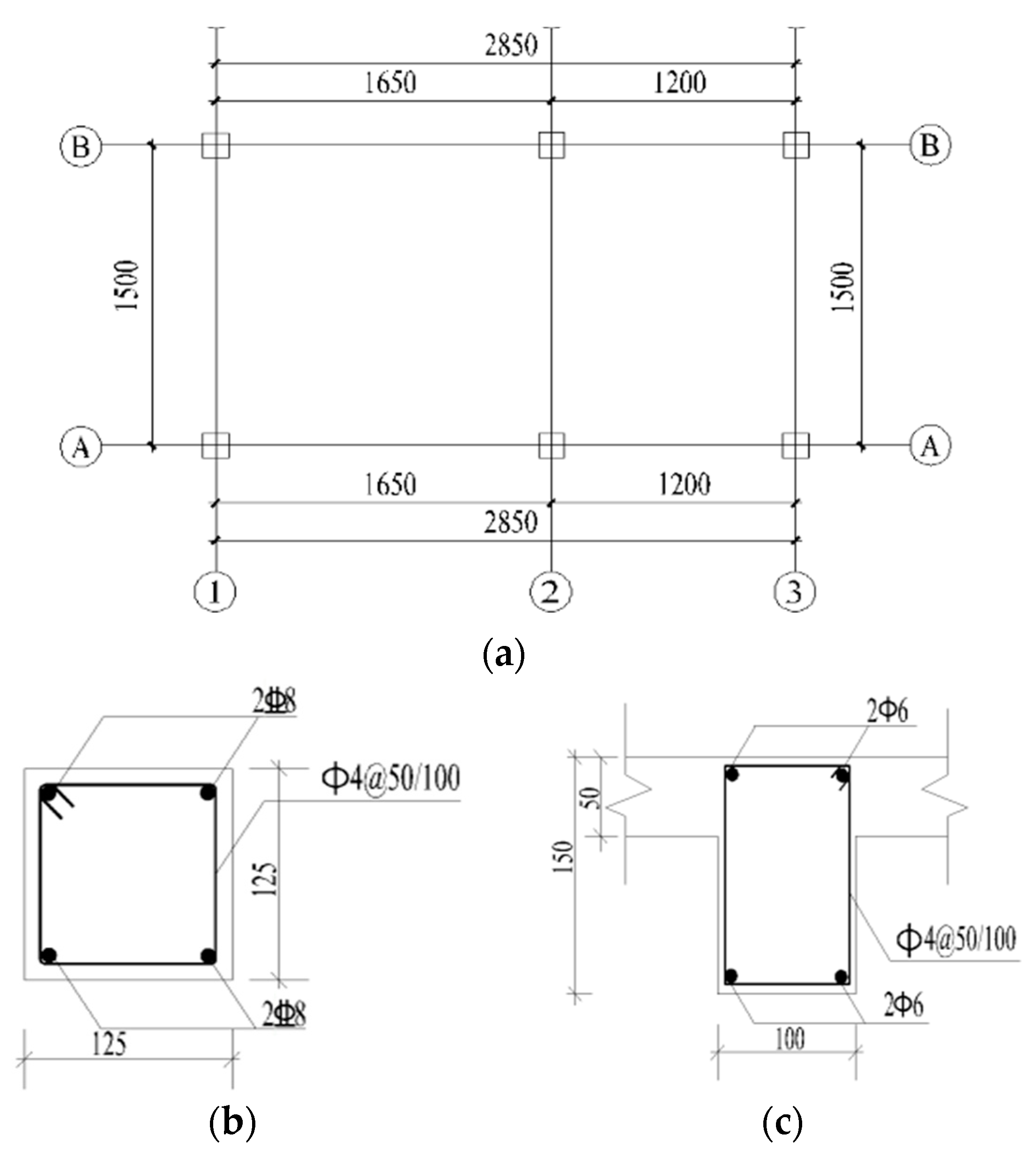
2.1. Prototype Structure

The prototype structure was a five-layer reinforced concrete framed building designed by the 7-degree seismic fortification intensity [43,44]. Structure elements’ dimensions were as follows: the section profile size of beams was 400 × 600 mm, the section profile size of columns was 500 × 500 mm, the compressive strength of concrete was 30 MPa, and the building plan of the prototype structure is shown in Figure 1.

2.2. The Design of Model and Similarity Relation

Based on the bearing capacity of the shaking table and the uniform similarity rate of the earthquake simulation experiment, the scale ratio of the model building was designed to 1:4. According to the Bukingham π theorem, the similar relationship between the model and the prototype was derived; see Table 1 [45]. The layer height of the 5-layer model building was 750 mm. Structural elements dimensions of the model were as follows: the cross-section size of the beam was 100 × 150 mm, and the cross-section size of the column was 125 × 125 mm. Considering the difficulty of construction and that the floor thickness of 25 mm cannot bear the weight of additional artificial quality placed on the floor, the thickness of the floor was 50 mm. Therefore, the extra weight of the floor was used as a counterweight on the floor. Detailed plans of section reinforcement of the model are shown in Figure 2.
According to the equivalent principle of bearing capacity, the structure reinforcement was designed as follows: bars with a diameter of 8 mm were used as longitudinal reinforcement in columns with a yield strength of 400 MPa. Bars with a diameter of 6 mm were used as longitudinal reinforcement in beams with a yield strength of 300 MPa. Galvanized wire of 10# was used as the stirrup.
The model structure was built with micro-concrete. Three groups of cube blocks and three groups of prism blocks of each layer were separately tested. The compressive strength of the cube blocks was 19.40 MPa, and the average elastic modulus value was 1.90 × 10⁴ Mpa. The electro-hydraulic servo universal testing machine carried out the tensile tests of reinforcing bars and galvanized iron wires used in the model. The yield strength and tensile strength of reinforcement are shown in Table 2. The elastic modulus similarity ratio, that is, Er, was 0.63. Considering the quality of the model and base plate and the maximum bearing capacity of the table, the total artificial mass added to the model was 8.9 t, including 1.7 t of the artificial mass per layer from the 1st to 4th floor and 2.1 t of the artificial mass on the roof.

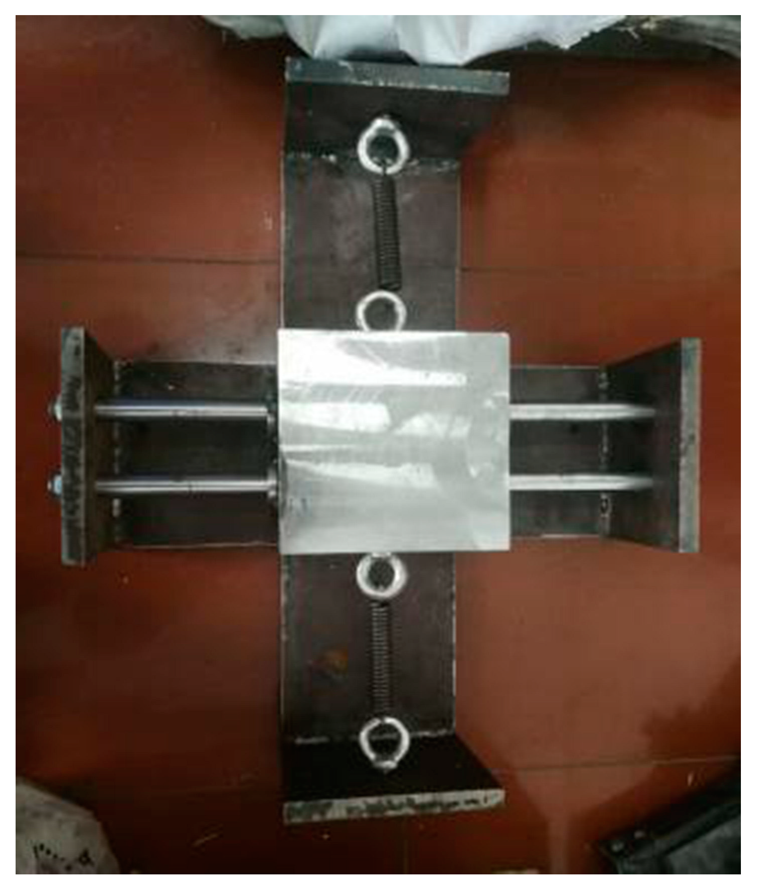
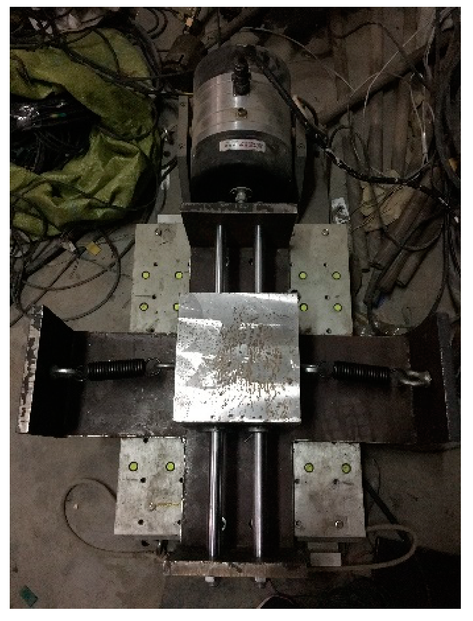
2.3. Design and Manufacture of NES

The plan drawing of NES is shown in Figure 3 and Figure 4, and the parameters of NES are shown in Table 3.
As shown in Figure 5, the frequency of NES was tested by the WS-Z30-50 small vibration table. The nonlinear stiffness of the spring varied during the vibration of the vibrator, and the natural frequency of the NES was measured between 3.8 Hz and 5.0 Hz. The natural frequency of the model frame structure was 4.9 Hz by the percussion mode test, which was within the natural frequency range of the NES. So, the characteristic of the broadband vibration absorption of NES can be achieved fully. The NES used in this experiment has a relatively large nonlinear stiffness and a wide vibration absorption frequency band. However, with the damage to the model RC frame structure, the structure’s natural frequency decreased correspondingly.

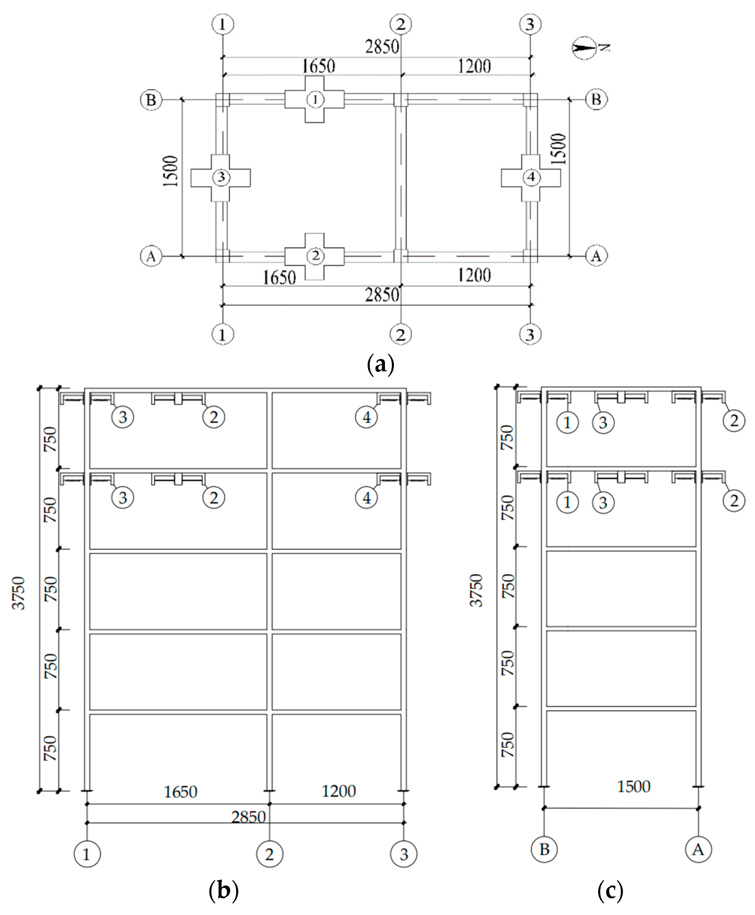
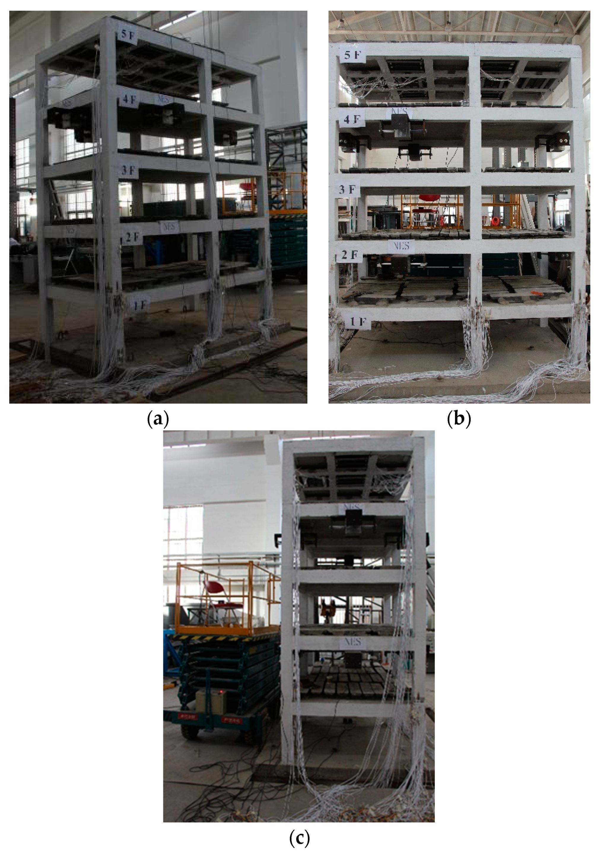
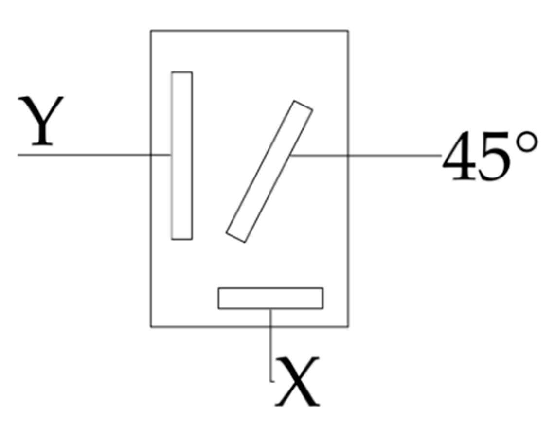
2.4. NES Arrangement and Test Point

The test contents mainly include the structure’s natural frequency, the strains of the reinforcement of beams and columns on the first and the second floors, and the concrete strain at the joints.
There were eight NESs fixed on the bottom of the beam with the embedded bolts on the fourth and fifth floors, respectively. The specific location of these NESs was shown in Figure 6. The RC frame model with NES is shown in Figure 7. The acceleration sensor was placed in the direction of X and Y on the first floor and top floor, respectively.
The plastic hinge development and the beam-column joint’s stress throughout the loading process were investigated. The strain gauges were placed on the beam end, the column top and foot, the beam-column joints, longitudinal reinforcements of beams and columns, and stirrups of joints. All strain gauges were connected to the dynamic strain test acquisition system for collection. The strain gauge layout of longitudinal reinforcements of beams is shown in Figure 8. The layout of the strain gauge of the A1 column is shown in Figure 9, which is the same as the A2 and A3 columns. The strain gauge arrangement can be seen in Figure 10.

2.5. Loading Sequence

In this paper, the Sichuan Wolong and El-Centro earthquake wave were inputted. The acceleration peak of each earthquake wave increased step by step. The earthquake wave’s acceleration peak and time interval were adjusted according to the Bockingham π theorem. Before and after each loading, the environmental excitation (pulsation method) was used to measure the change in the natural frequency of the model frame structure; see Figure 11. The power spectrum of the model was measured and later converted into a response spectrum. Loading conditions of the test are shown in Table 4.

3. Results and Discussion

3.1. Damage Process and Assessment

After inputting the first earthquake wave (T1), there were some slight cracks at the junction between beam and column and the bottom of the column on the first floor caused by concrete cracking in tension, and there were no visible cracks on the second floor and above.
After inputting the second earthquake wave (T2), some parts of the concrete at the bottom of the column were crushed. Multiple vertical cracks developed from the column ends to tops on the first floor, as some small cracks with a width of less than 0.05 mm appeared at the ends of the beam on the second floor. Bending cracks developed from the bottom of the beam end to the beam column joints.
After inputting the third earthquake wave (T3), the concrete at the bottoms of the columns in the four corners was crushed, while slight horizontal cracks in the foot of the column developed; the cracks at the ends of beams enlarged and began to peel off. After that, there were wider cracks at the joints on the first floor than on the second floor.
After inputting the fourth earthquake wave (T4), more crushed concrete areas were at the foot of the columns. Longitudinal reinforcements at the ends began to yield, and the cracks at the ends of beams widened to 0.15 mm on the first floor. Crossing cracks appeared in the exterior joints, and crushed concrete began to peel off. The vertical cracks at the beams’ ends became wider on the second floor and above, as shown in Figure 12.
After inputting the fifth and sixth earthquake waves (T5 and T6), most of the longitudinal reinforcements in joints had yielded. Concrete at the foot of exterior columns was crushed on the first floor, and reinforcements were exposed. At the same time, 0.5 mm width horizontal cracks developed along the edge of the column foot, which caused the apparent failure of the end of the column. In the A2 joint, some concrete cover dropped away, and reinforcements were exposed, while vertical cracks at the beams widened, and exterior joint crossing cracks extended from the bottom to the section top. A cross-cut oblique crack developed at one of the side joints. Some vertical cracks of corner joints penetrated the whole section. On the second floor and above, cracks on the beams developed from ends to the joint interior, but no apparent cracks developed at the column top. The final destruction is shown in Figure 13.
The ends of beams yielded firstly under earthquake, as the columns were not damaged at the beginning. With the increasing earthquake magnitude, cracks at the end of the beams extended to the joint interior rapidly, finally causing crossing cracks to appear in exterior joints, and vertical cracks of corner joints penetrated the whole section. On the first floor, more cracks at the ends of beams and horizontal cracks came into being at the foot of the columns. There was no failure at the end of columns on other floors. It showed that NES could effectively reduce earthquake damage and postpone the failure at the column’s end. The mechanism of “strong column and weak beam” was realized by NES. The final failure of the frame structure was due to the broken concrete at the column foot, the exposed reinforcements, and the loosened column foot.

3.2. Natural Frequency

Before and after inputting the earthquake waves, the natural frequency of the RC frame structure was determined by the fluctuation approach. The natural frequency of the model structure is shown in Table 5, and the f0 was the natural frequency measured before the test. When the NES shock absorber was in T1 and T2 working conditions, the natural frequency decreased by 11%, and the average reduction rate was 5.5% as PGA reached 0.2 g. At the same time, the structure was in an elastic condition, the steel bars were still not yielding, and the structure was slightly failed. When the NES was locked in T3 and T4 conditions, the natural frequency’s fall rate decreased by 11%, and the average reduction rate was 9.2%. At the end of the test, the natural frequency dropped to 53.1%, the structural failure was more significant, and the cracking was severe. The decreasing of natural frequencies indicated the failure and degradation of structural stiffness. With the increasing PGA, the structure gradually cracked until heavy failure was observed when the natural frequency decreased. With the 0.2 g PGA, the natural frequency of the structure with NES was lower than that of the standard structure. When PGA was 0.4 g in T5 and T6 conditions, the decreasing rate of the structure’s natural frequency was approximate to the T1 and T2 conditions. From Table 5, it can be observed that NES can bring down the degree of damage to the structure effectively and improve the seismic capacity of the structure.
As the connection between the column end and the shaking table became loose, the concrete at the column foot was broken, and the steel bar at the column end yielded. The reinforced concrete frame structure can no longer bear the vertical load and horizontal shear force because of the failure of the column end.

3.3. Steel Strain

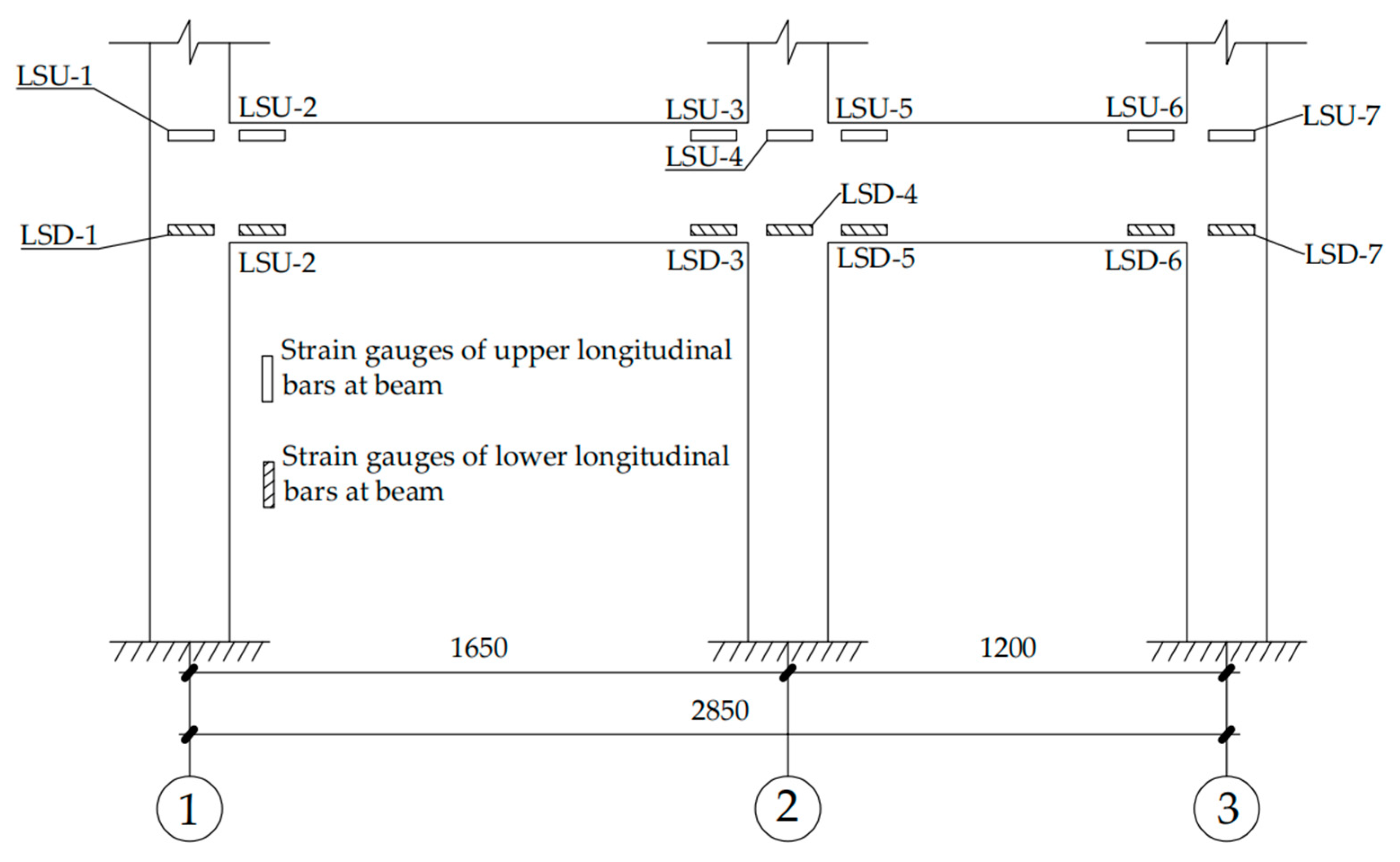
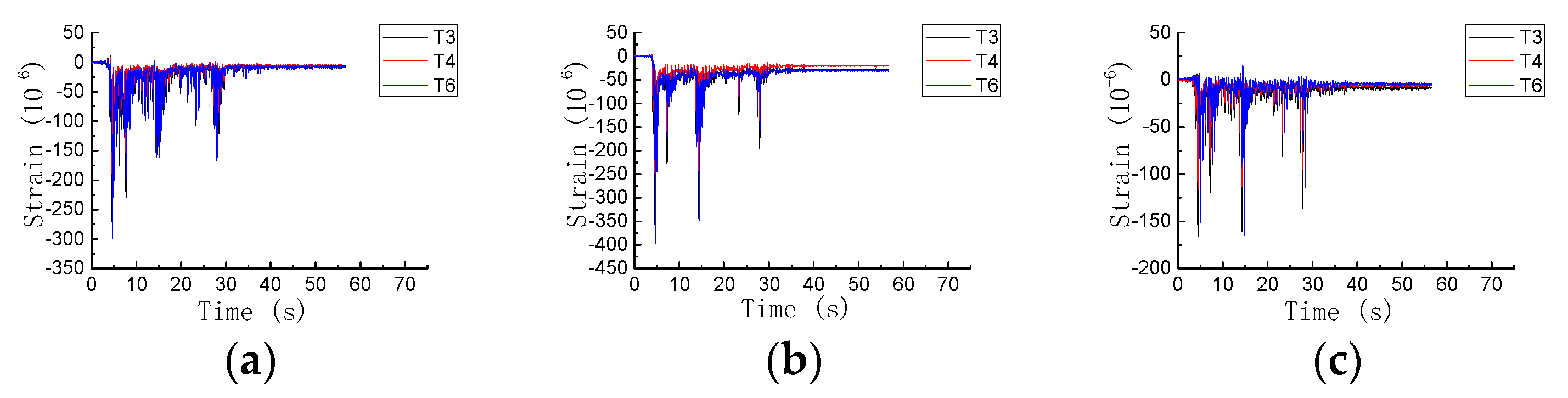
3.3.1. Strain of Longitudinal Reinforcements of Beam

The maximum strain of the compressive and tensile bars in beams is presented in Table 6. The data in Table 6 show that the maximum strain of longitudinal reinforcements at the end of beams was greater than that of longitudinal reinforcement at joints. Consequently, flexural failure and cracking of the end of the beam occurred earlier than the failure of the joint, which is in agreement with the experimental investigation.
When the PGA of T1 and T2 conditions was 0.2 g, all longitudinal bars of the beam were in the elastic stage. After T3 and T4 conditions, the longitudinal reinforcements of the beam ends were almost yielded. The longitudinal bars of columns were still in the elastic stage when the vertical bending cracks occurred at the end of beams. The failure mode showed bending failure at the end of beams. Most longitudinal bars of beams yielded, and plastic hinges appeared at the ends of beams in T5 and T6 conditions.
According to the comparison of the maximum strain of longitudinal bars in the beams between T1 and T3 conditions with 0.2 g PGA under the Wolong earthquake waves, the strains of the joints’ upper and lower longitudinal reinforcements decreased by 40.1% and 57.9%, respectively. In comparison, the strains of the upper and lower longitudinal reinforcements in beam ends decreased by 58.9% and 35.4%, respectively, under the El-Centro earthquake waves with 0.2 g PGA. The strains of the upper longitudinal reinforcements in the joints and at the beam ends decreased by 7.5% and 7.8%, respectively. Meanwhile, most of the strain gauges attached to the bottom surface of the beam were disabled because of the yielded longitudinal reinforcements at the bottom of the beams. As mentioned above, the stress of the longitudinal reinforcement in the beam can be decreased obviously, and the plastic hinge production and joints’ shear failure were delayed by NES when the gradual loading method was adopted. As a result, the seismic capacity of the structure was improved.

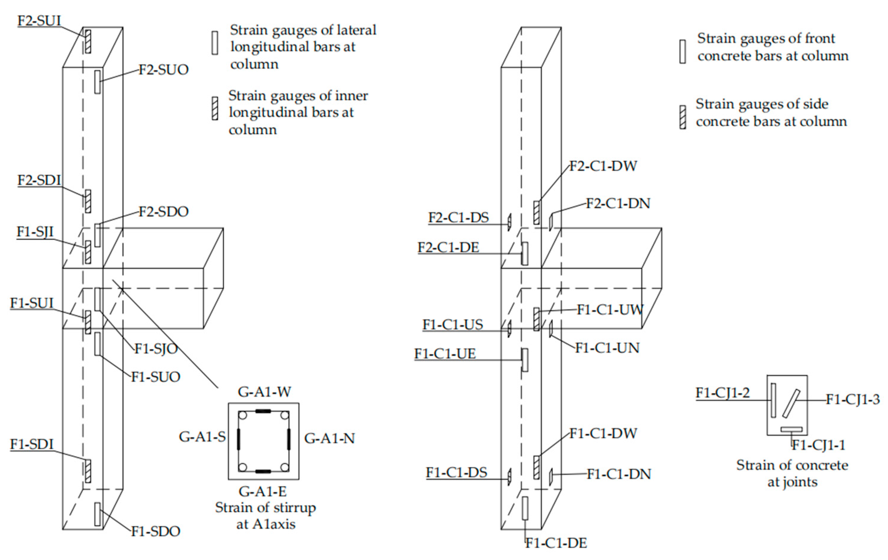
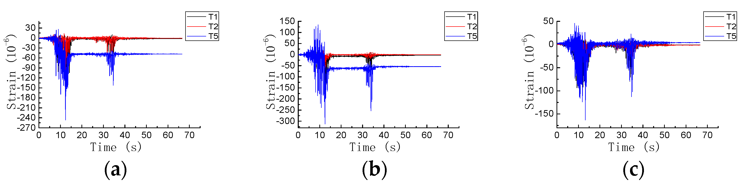
3.3.2. Strain of Longitudinal Reinforcements of Column

The maximum strain observed values of strain gauges of longitudinal reinforcements of columns as shown in Table 7. After T1 and T2 conditions with 0.2 g PGA, all longitudinal bars of columns were in the elastic stage. Similarly, after T3 and T4 conditions with 0.2 g PGA, the stress of longitudinal columns’ longitudinal bars increased significantly but were still in the elastic stage. Finally, in T5 and T6 conditions, the stress of longitudinal reinforcements of columns increased rapidly to yielding, and some strain gauges attached to the longitudinal reinforcements of columns failed. In contrast, concrete at the column foot was crushed.
After the T4 working condition, strains of longitudinal bars of columns were in the elastic stage, and the tensile longitudinal reinforcements of beams were yielded, so the mechanism of “strong column and weak beam” was realized. The strains of longitudinal reinforcement of columns when NES was working were less than the strains of structure with locked NES in the same conditions. This paper took the A2 column as an example: the maximum strain at the bottom of the structure column with NES was reduced by 63.5% under the Wolong earthquake waves and 41.4% under the El-Centro earthquake waves compared with the structure without NES. Therefore, the NES can decrease the stresses and strains of the longitudinal reinforcement of columns significantly and the seismic response of the whole structure, thus the seismic capacity of the structure can be improved.

3.3.3. The Strain of Stirrups in Joints

The maximum strain of stirrups at joints of this reinforced concrete frame structure is shown in Table 8. The strains of stirrups in joints with working NES were less than those with locked NES in the same conditions. Under the Wolong and El-Centro earthquake waves, the minimum reductions were 18% and 9.8%, respectively. From T1 to T4 working conditions, the strains of stirrups showed little change. The maximum strain of stirrups was 826 × 10−6 and was far away from the yielding strength. The result is because the shear strength of the joints mainly depends on the concrete’s tensile strength, and the joint’s force-transferring mechanism was expressed as a diagonal compressive element mechanism.
After inputting 0.4 g earthquake waves (T5 and T6 conditions), some parts of the concrete stopped working and strains of the stirrups increased significantly, even up to the yielding strength, while the force transferring mechanism of the joints was changed from “diagonal compressive element mechanism” to “truss mechanism.” As a result, the stirrups not only resisted shear forces, but also restrained the expansion of concrete and improved the shear capacity of concrete to a certain extent.

3.4. Strains and Shear Stresses of Concrete in Joints

Figure 14 and Figure 15 showed the strain–time curves of the inclined concrete in joints in T1 and T2 conditions when the PGA was 0.2 g. Under the Wolong and El-Centro earthquake waves, the distribution of tensile strains and compressive strains at all joints were unsymmetrical, and the compressive strains were more significant than the tensile strains, which proved that a “diagonal compression element mechanism” existed in joints. The structure had experienced secondary seismic wave input and had accumulated damage, which also led to increased structural node strain in the T5 working condition.
The maximum diagonal strains of concrete in T1 and T2 working conditions with opening NES were less than in T3 and T4 working conditions with locked NES. The strains of concrete in joints in T1 and T2 conditions eventually returned to the equilibrium position, while the strains in the T3 and T4 conditions finally deviated from the equilibrium position. The NES can decrease the internal force and reduce the shear failure of the concrete at the joints effectively, then postpone the concrete stopping working.
By measuring concrete strain gauges at joints, the shear strains can be indirectly obtained to investigate the influence of NES on the horizontal shear force of frame joints. The horizontal shear force can be derived as follows:
ε α = 1 2 ( ε x + ε y ) + 1 2 ( ε x ε y ) cos 2 α + 1 2 γ x y
When the rectangular section is subjected to shear force FS, the shear stress on the section is parabolic. Therefore, the maximum shear stress at the center of the section can be derived as follows:
τ m a x = 3 F s 2 A
The shear strength of the whole section is shown as follows:
F s = 2 3 τ m a x A = 2 3 ( 2 ε 45 ° ε x ε y ) G A
In Equations (1)–(3), γxy is the shear strain at joint; ε x , ε y and ε 45 are strains of the X direction, Y direction, and 45°direction, respectively. The strain direction at the node is as shown in Figure 16; A is a sectional area (unit: m2), τ max is the shear stress at joints (unit: GPa, Fs is the shear of joints (unit: kN), and G is the Shear modulus (unit: GPa).
Due to the large plastic deformation of concrete in T5 and T6 conditions, the shear stress from T1 to T4 working conditions was analyzed. The calculation results of the shear force at joints are shown in Table 9.
According to Table 9, the maximum shear stress was at the exterior joint of the A2 column, while the minimum shear stress was at the corner joint of the A3 column. The different lateral stiffness of these three columns is the main factor affecting the shear stresses and axial strains of A1, A2, and A3 columns. Under Wolong and El-Centro earthquake waves with 0.2 g PGA, the horizontal shear force of the RC frame structure with working NES was decreased by 67% and 33%, respectively, at least compared with the RC frame structure with locking NES.

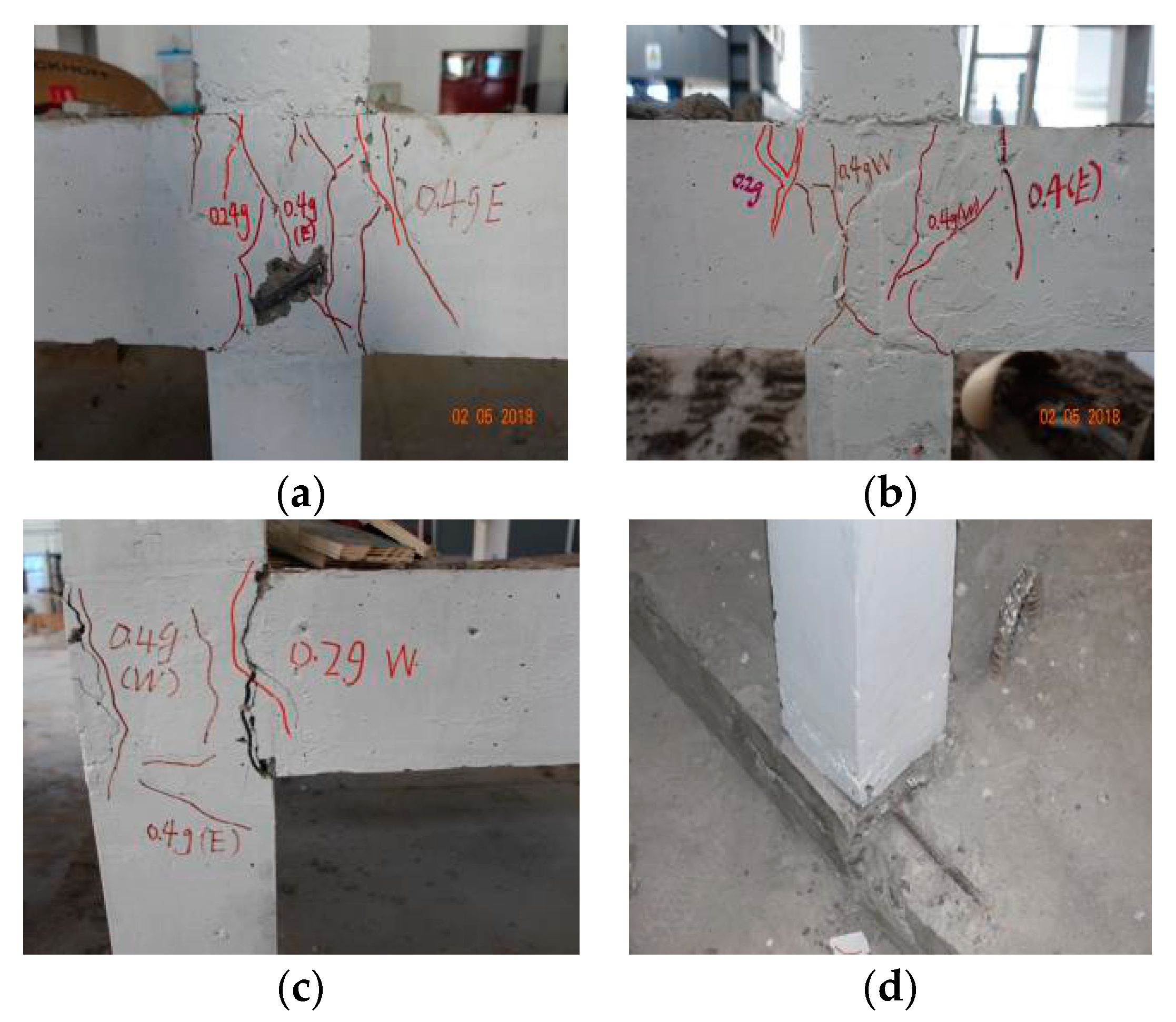
3.5. Failure Mode of Joints

From Table 6, Table 7 and Table 8, the longitudinal reinforcements of beam ends were in an elastic state in T1 and T2 conditions. In T3 and T4 conditions, the longitudinal reinforcements of beams began to yield partially, while the longitudinal bars of columns were still in the elastic stage. Therefore, the plastic hinges occurred at the ends of the beams. The main compressive strains of concrete in the core area of joints were 0.002~0.003, which was close to the concrete’s ultimate compressive strains. Therefore, bending failure occurred at the ends of beams. In T5 and T6 conditions of 0.4 g PGA, the stresses of the longitudinal reinforcements of the beams reached the yielding point, and part of the bars of the columns began to yield. Then the strains of the stirrups increased significantly and yielded partially. At the same time, shear failure occurred at some joints, and compressive bending failure happened at the ends of the columns.
At the exterior joint, the bending failure of beam ends first occurred, and then cross diagonal cracks appeared, all of which showed typical joint combined failure, including shear failure and plastic hinge of the beam ends. Multiple vertical cracks were produced at the corner joints, a single bending failure of the beam ends. The slight failure of the column ends at partial joints was observed. Therefore, the joints’ seismic characteristics and the working condition were improved by NES obviously, and the failure of the column ends was also reduced to some extent.

4. Analysis of Nodal Shear Strength

4.1. Theoretical Calculation for Nodal Shear Strength

Based on the existing tension–compression element model, Hwang et al. [46] further considered the influence of the softening effect of concrete on the shear strength of joints and proposed a softening tension–compression element model. The analytical model satisfies the static equilibrium condition of the node core area, the Mohr coordination condition, and the softening biaxial constitutive relation of the concrete. The analysis model consists of horizontal, oblique, and vertical mechanisms. Among them, the oblique mechanism is an oblique pressure element formed by diagonal concrete in the core area of the node, as shown in Figure 17a. The horizontal mechanism consists of one horizontal tie element and two horizontal compression elements. The stirrups at the nodes provide the horizontal tie elements, and the oblique concrete provides the horizontal compression elements, as shown in Figure 17b. The vertical mechanism consists of one vertical tie element and two steep pressure elements. The vertical tie element is provided by the steel bar in the middle of the column, and the steep pressure element is provided by the obliquely compressed concrete, as shown in Figure 17c.
The shear bearing capacity V j of the node area is calculated as follows:
V j = ζ K f c b j a s c o s θ
In Equation (4):
ζ is the concrete softening coefficient;
K is the coefficient of the tension and compression element;
f c is the compressive strength of concrete axis (unit: MPa);
a s is the effective height of the oblique pressure element (unit: mm);
b j is effective width of node (unit: mm);
θ is the included angle between the oblique pressure element and the horizontal.
The shear force in the core area of the node is mainly borne by the compression element formed by the concrete at the node. The horizontal stirrups and vertical steel bars in the core area can restrain the concrete inside the joint so that more concrete forms pressure elements to participate in the force, thereby improving the shear strength of the joint. There are tie elements formed by horizontal stirrups and vertical middle column reinforcements in the core area of the node. The oblique compression adds an additional force transmission path based on the transmission of the oblique compression steel bars so that more concrete participates in the shear resistance and improves the resistance of the joint. The coefficients in the formula are calculated as follows:
ζ = 3.35 f c = 3.35 19.4 = 0.76
In Equation (5), h b and   h c (unit: mm) represent the distance between the centerlines of the outermost longitudinal bars of beams and columns, respectively.
In this model, take h b = 124 , h c = 97 ,
θ = arctan ( h b h c ) = arctan ( 124 97 ) = 51.97 °
b j is the depth of the oblique bar, generally the width of the column, b j = b c = 125   mm .
The oblique bar height a s is calculated by the following formula:
a s = c b 2 + c c 2
,
In Equation (6), c b (unit: mm) represents the height of the compression zone of the beam section, which is taken as h b 5 ; c c (unit: mm) is the height of the compression zone of the column section, which is calculated by the following:
c c = ( 0.25 + 0.85 N c f c b c h c ) h c
where:
N c is the axial pressure of the concrete column, the design value of the axial force of the column is adopted (unit: N);
b c is the width of the column section, taken as 125 mm;
h c is the height of the column section, taken as 125 mm;
To calculate N c , use the following Equations (8) and (9):
N = n A q
N c = 1.25 c β N
where:
n is the number of floors supported by the column;
A is the subordinate area of the column (unit: mm2);
q is the standard value of vertical load (unit: N/mm2);
c is the center column c = 1.0, side column c = 1.1, corner column c = 1.2;
β is the magnification factor of the horizontal force to the axial force of the column, which is taken as 1.05 for the seventh degree earthquake resistance;
From the model structure floor plan, the column subordinate area A   i s   1.069 × 10 6   mm 2 .
Standard value of vertical load:
q = m g A
Among them, g is the gravitational acceleration (unit: N/kg), m is the sum of the model self-weight and additional mass, and here its value is 14,464 kg.
A is the total area of the structural plane, so calculated:
c c = ( 0.25 + 0.85 N c f c b c h c ) h c = 102.98   mm
where a s = 107.26 mm.
The coefficient K is calculated as follows:
K = K h + K v 1
where:
K h is horizontal tie element coefficient;
K v is the vertical tie element coefficient;
Calculate the following:
K h = 1 + ( K h ¯ 1 ) A t h f y h F h ¯
K v = 1 + ( K v ¯ 1 ) A t v f y v F v ¯
K h ¯ 1 1 0.2 ( r h + r h 2 )
K v ¯ 1 1 0.2 ( r v + r v 2 )
r h = 2 t a n θ 1 3
r v = 2 c o t θ 1 3
F h ¯ = r h × ( K h ¯ ζ f c a s b j ) × c o s θ
F v ¯ = r v × ( K v ¯ ζ f c a s b j ) × s i n θ
where:
A t h , A t v are the cross-sectional area of the horizontal tie element and the vertical tie element, respectively (unit: mm2);
f y h , f y v are the yield strength of the steel bars used in the horizontal and vertical tie elements, respectively (unit: MPa);
F h ¯ , F v ¯ are the balance tension of the horizontal tie element and the vertical tie element (unit: N);
K h ¯ , K v ¯ are the balance coefficients of the horizontal tie element and vertical tie element;
r h , r v is the ratio of the horizontal tie element, vertical tie element and the horizontal shear force of the node;
A t h   i s   25.13   mm 2 ;
f y h and f y v are, respectively, 413 MPa and 523 MPa;
Then obtain the theoretical shear bearing capacity V j as follows:
V j = ζ K f c b j a s c o s θ = 107.49   K N

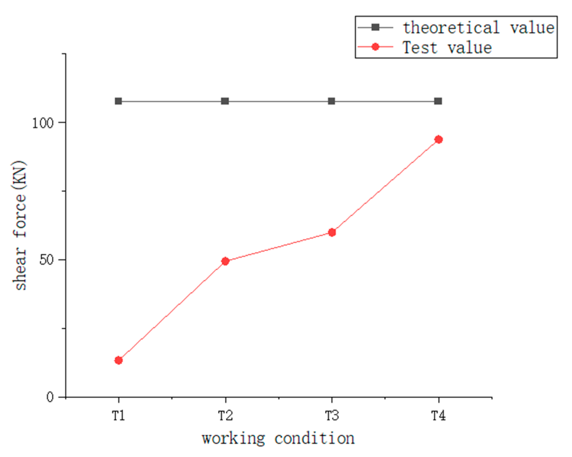
4.2. Analysis of Theoretical Strength and Experimental Ones

It can be seen from Table 9 that the shear force value at node A2 under various working conditions has the following relationship with the theoretical shear force value at node A2.
As seen from Figure 18, in the T1–T3 working conditions, the node was slightly damaged for the shear force at node A2 below the ultimate the theoretical bearing capacity, V j . From the beginning of the T4 working condition, the concrete at the A2 node began to peel off, and a cross-oblique crack appeared and gradually extended into the node, and the crack width was also widened simultaneously. In the T4 condition, although the stress of the node is still in the elastic stage, the primary compressive strain of the concrete was close to the ultimate compressive strain, and the A2 node was severely damaged, which was consistent with the node strength values obtained by theoretical analysis.
In Figure 19, it showed that before the T4 condition, the stirrup strain at node A2 exhibited a minor change. The shear force of the stirrup is small also, indicating that no large cracks occurred in the concrete at this stage. After the T4 working condition, the strains of the stirrups in the west and east suddenly increased, indicating that the concrete was severely damaged, and the stirrups participated in the shear resistance.

5. Discussion

Previous research had focused on the working principle, damping and mass ratio of NES, and generally applied NES to steel structures with light dead weight. This experiment provided new insights into the design parameters of NES shock absorbers and applied NES to large mass RC frame structures, focusing on the effects on frame joints.
A reduction in natural frequency indicates failure and the degradation of structural stiffness. In this section, the seismic failure of the structure under various working conditions was discussed. In the T3 and T4 working conditions, that is, when PGA = 0.2 g and NES is locked, the natural frequency decline rate decreases by 11%, and the average decline rate is 9.2%. In the T5 and T6 working conditions, that is, PGA = 0.4 g, when the NES is unlocked, the natural frequency decreases by an average of 9.15%. Considering the large increase in the peak acceleration and the cumulative damage of the structure, the NES fully plays the role of tuning and damping, which can effectively reduce the damage degree of the structure and improve the seismic capacity of the structure.
Furthermore, by comparing and analyzing the T1 and T3 working conditions, the maximum stress and strain of the node reinforcement in the T3 working condition with the unlocked NES are almost 50% lower than those in the T2 working condition with the locked NES. NES can significantly reduce the stress and strain of longitudinal reinforcement in beams, delay the occurrence of plastic hinges and the shear failure of joints.
Whether it is an ordinary structure or an NES damping structure, the plastic hinge first appears at the beam end, and then shear failure occurs at the node. However, NES can reduce the tensile force at the joint, reduce the shear failure range of concrete, effectively reduce the internal force shear at the joint, delay the occurrence of shear failure, and be more conducive to the realization of seismic measures.

6. Conclusions

The research results show that through the careful design of the nonlinear stiffness and frequency of the NES, the NES would have a good damping effect on the RC frame structure with a large self-weight.
(1)
According to the natural frequency analysis, when the PGA increased from 0.2 g to 0.4 g, the natural frequency decline rate of the frame structure using NES was close to that of the ordinary frame structure without NES, which verifies that the NES has a noticeable effect on improving the seismic capacity of RC frame structures.
(2)
The strains of reinforced concrete beams, columns, and stirrup can be reduced effectively up to 50% by NES, and the plastic hinges at the beam ends were delayed in their occurrence. The plastic hinge first appeared at the beam ends, following by the shear failure at the joints; NES is more helpful in realizing the seismic measures.
(3)
Under the earthquake, the tensile and compressive strains at joints of the RC frame structure with NES were distributed asymmetrically. As a result, compressive stresses were greater than tensile stresses, representing a failure mode of the “diagonal compression bar mechanism” at joints. So, NES can reduce the shear failure range of concrete and effectively decrease the internal forces shear at joints.
(4)
The reinforcements at the column ends were yielded and could not firmly connect the columns with the model structure foundation. Then the bearing capacity of the column bases disappeared, which caused the ultimate failure of the NES-added RC frame structure.
(5)
In the final stage of the test, when the stress and strain are less than the theoretical calculation value, serious damage occurs, indicating that the actual bearing capacity is lower than the theoretical calculation value.

Author Contributions

Conceptualization, H.Y.; methodology, H.Y. and B.Y.; validation, B.Y. and M.Z.; formal analysis, H.Y. and H.W.; investigation, B.Y.; resources, S.N.; data curation, H.Y.; writing—original draft preparation, H.Y.; writing—review and editing, H.Y., B.Y., H.W., S.N. and M.Z.; visualization, B.Y.; supervision, H.Y.; project administration, H.W.; funding acquisition, H.Y. and H.W. All authors have read and agreed to the published version of the manuscript.

Funding

This research was funded by the National Natural Science Foundation of China (NSFC), grant number, 51878130 and Key Laboratory of Building Collapse Mechanism and Disaster Prevention, China Earthquake Administration, grant number, FZ201105.

Institutional Review Board Statement

Not applicable.

Informed Consent Statement

Not applicable.

Data Availability Statement

Not applicable.

Acknowledgments

The writers appreciate the participation and contributions of collaborators from Yongcheng Ji.

Conflicts of Interest

The authors declare no conflict of interest.

References

  1. Ye, L.P.; Lu, X.Z. Analysis on seismic damage of buildings in the Wenchuan earthquake. J. Build. Struct. 2008, 29, 1–9. [Google Scholar]
  2. Zhan, Y.X.; Jiang, L.M.; Tang, C.Q.; Wu, C.L. A numerical simulation analysis of the influence of axial compression ratio on the seismic capacity. J. Hunan Univ. Technol. 2017, 31, 30–34, 40. [Google Scholar]
  3. Pantelides, C.P.; Hansen, J.; Nadauld, J.; Reaveley, L.D. Assessment of Reinforced Concrete Building Exterior Joints with Substandard Details; University of California, Berkeley: Berkeley, CA, USA, 2002. [Google Scholar]
  4. Park, S.J.; Mosalam, K.M. Experimental and Analytical Studies on Reinforced Concrete Buildings with Seismically Vulnerable Beam-Column Joints; University of California, Berkeley: Berkeley, CA, USA, 2012. [Google Scholar]
  5. Masi, A.; Santarsiero, G.; Lignola, G.P.; Verderame, G.M. Study of the seismic behavior of external RC beam-column joints through experimental tests and numerical simulations. Eng. Struct. 2013, 52, 207–219. [Google Scholar] [CrossRef]
  6. Fu, J.P.; Zhang, C.; Chen, T.; Bai, S.L. Experimental investigation of shear mechanism and effect of axial-compression ratio on joints in earthquake-resistant reinforced concrete frames. J. Build. Struct. 2006, 3, 67–77. [Google Scholar]
  7. Chen, L.L.; Yu, J.; Wang, J. Factors analysis and polarization parameters research on failure modes of reinforced concrete frame joints. Build. Struct. 2012, 42, 76–80, 92. [Google Scholar]
  8. Fan, G.X.; Song, Y.P.; Wang, L.C.; Wang, D.B. Experimental study of the influence of strain rate on the dynamic performance of interior reinforced concrete beam-column joints. China Civ. Eng. J. 2014, 47, 11–18. [Google Scholar]
  9. Vakakis, A.F.; Gendelman, O.V. Energy Pumping in Coupled Mechanical Oscillators, Part II: Resonance Capture. Trans. ASME J. Appl. Mech. 2001, 68, 42–48. [Google Scholar] [CrossRef]
  10. Nucera, F.; Vakakis, A.F.; McFarland, D.M.; Bergman, L.A.; Kerschen, G. Targeted Energy Transfer in Vibro-impact Oscillators for Seismic Mitigation. Nonlinear Dyn. 2007, 50, 651–677. [Google Scholar] [CrossRef]
  11. Starosvetsky, Y.; Gendelman, O. Attractors of the harmonically forced linear oscillator with attached nonlinear energy sinkII: Optimization of nonlinear vibration absorber. Nonlinear Dyn. 2008, 50, 47–57. [Google Scholar]
  12. Zhang, Y.C.; Kong, X.R. Initial conditions for targeted energy transfer in coupled nonlinear oscillators. J. Harbin Inst. Technol. 2012, 44, 21–26. [Google Scholar]
  13. Wang, J.J.; Zhang, C.; Liu, Z.B.; Li, H.B. Experimental Research and Robustness Analysis of Asymmetric Nonlinear Mass Damper. J. Vib. Shock. 2022, 41, 176–182, 237. [Google Scholar]
  14. Wang, J.J.; Li, H.B.; Liu, Z.B. Research on the vibration reduction performance of high-rise structures with additional orbital nonlinear energy wells. J. Vib. Shock. 2020, 39, 173–180. [Google Scholar]
  15. Li, S.; Lou, J.J.; Liu, S.Y.; Chai, K. Analysis of vibration suppression effect of nonlinear energy well under shock excitation. J. Huazhong Univ. Sci. Technol. Nat. Sci. Ed. 2019, 47, 87–92. [Google Scholar]
  16. Yao, Y.Y.; Song, W.Z.; Li, B.; Chen, Z.Y.; Zhang, C.J.; Gao, Q. Analysis of NES Vibration Suppression Based on Energy Dissipation. Chin. J. Constr. Mach. 2020, 18, 384–389. [Google Scholar]
  17. Wang, J.J.; Wierschem, N.; Spencer, B.F.; Lu, X.L. Experimental study of track nonlinear energy sinks for dynamic response reduction. Eng. Struct. 2015, 94, 9–15. [Google Scholar] [CrossRef]
  18. Wang, F.X.; Ding, H. Mass design of nonlinear energy sinks. Eng. Struct. 2022, 250, 113438. [Google Scholar] [CrossRef]
  19. Dekemele, K.; Torre, P.V.; Loccufier, M. Design, construction and experimental performance of a nonlinear energy sink in mitigating multi-modal vibrations. J. Sound Vib. 2020, 473, 115243. [Google Scholar] [CrossRef]
  20. Zang, J.; Zhang, Y.W.; Hu, D.; Yang, T.Z.; Chen, L.Q. The evaluation of a nonlinear energy sink absorber based on the transmissibility. Mech. Syst. Signal Process. 2019, 125, 99–122. [Google Scholar] [CrossRef]
  21. Bab, S.; Khadem, S.; Mahdiabadi, M.; Shahgholi, M. Vibration mitigation of a rotating beam under external periodic force using a nonlinear energy sink (NES). J. Vib. Control. 2017, 23, 1001–1025. [Google Scholar] [CrossRef]
  22. Li, W.K.; Wierschem, N.E.; Li, X.; Yang, T.J. On the energy transfer mechanism of the single-sided vibro-impact nonlinear energy sink. J. Sound Vib. 2018, 437, 166–179. [Google Scholar] [CrossRef]
  23. Qiu, D.; Seguy, S.; Paredes, M. Design criteria for optimally tuned vibro-impact nonlinear energy sink. J. Sound Vib. 2019, 442, 497–513. [Google Scholar] [CrossRef] [Green Version]
  24. Zhang, Y.W.; Yuan, B.; Fang, B.; Chen, L.Q. Reducing thermal shock-induced vibration of an axially moving beam via a nonlinear energy sink. Nonlinear Dyn. 2017, 87, 1159–1167. [Google Scholar] [CrossRef]
  25. Guo, H.L.; Liu, B.; Yu, Y.Y.; Cao, S.Q.; Chen, Y.S. Galloping suppression of a suspended cable with wind loading by a nonlinear energy sink. Arch. Appl. Mech. 2017, 87, 1007–1018. [Google Scholar] [CrossRef]
  26. Boroson, E.; Missoum, S. Stochastic optimization of nonlinear energy sinks. Struct. Multidisc. Optim. 2017, 55, 633–646. [Google Scholar] [CrossRef]
  27. Zhang, Y.W.; Hou, S.; Zhang, Z.; Zang, J.; Ni, Z.Y.; Teng, Y.Y.; Chen, L.Q. Nonlinear vibration absorption of laminated composite beams in complex environment. Nonlinear Dyn. 2020, 99, 2605–2622. [Google Scholar] [CrossRef]
  28. Geng, X.F.; Ding, H. Two-modal resonance control with an encapsulated nonlinear energy sink. J. Sound Vib. 2022, 520, 11667. [Google Scholar] [CrossRef]
  29. Jin, Y.Z.; Liu, K.F.; Xiong, L.Y.; Tang, L.H. A non-traditional variant nonlinear energy sink for vibration suppression and energy harvesting. Mech. Syst. Signal Process. 2022, 181, 109479. [Google Scholar] [CrossRef]
  30. Qiu, D.; Paredes, M.; Seguy, S. Variable pitch spring for nonlinear energy sink: Application to passive vibration control. Proc. Inst. Mech. Eng. Part C J. Mech. Eng. Sci. 2019, 233, 611–622. [Google Scholar] [CrossRef]
  31. Chen, H.Y.; Mao, X.Y.; Ding, H.; Chen, L.Q. Elimination of multimode resonances of composite plate by inertial nonlinear energy sinks. Mech. Syst. Signal Process. 2020, 135, 106383. [Google Scholar] [CrossRef]
  32. Chen, J.E.; Sun, M.; Hu, W.H.; Zhang, J.H.; Zhou, C.W. Performance of non-smooth nonlinear energy sink with descending stiffness. Nonlinear Dyn. 2020, 100, 255–267. [Google Scholar] [CrossRef]
  33. Fang, B.; Theurich, T.; Krack, M.; Bergman, L.A.; Vakakis, A.F. Vibration suppression and modal energy transfers in a linear beam with attached vibro-impact nonlinear energy sinks. Commun. Nonlinear Sci. Numer. Simul. 2020, 91, 105415. [Google Scholar] [CrossRef]
  34. Zang, J.; Yuan, T.C.; Lu, Z.Q.; Zhang, Y.W.; Ding, H.; Chen, L.Q. A lever-type nonlinear energy sink. J. Sound Vib. 2018, 437, 119–134. [Google Scholar] [CrossRef]
  35. Tan, D.D.; Lu, Z.Q.; Gu, D.H.; Ding, H.; Chen, L.Q. A ring vibration isolator enhanced by a nonlinear energy sink. J. Sound Vib. 2021, 508, 116201. [Google Scholar] [CrossRef]
  36. Dekemele, K.; de Keyser, R.; Loccufier, M. Performance measures for targeted energy transfer and resonance capture cascading in nonlinear energy sinks. Nonlinear Dyn. 2018, 93, 259–284. [Google Scholar] [CrossRef]
  37. Li, T.; Gourc, E.; Seguy, S.; Berlioz, A. Dynamics of two vibro-impact nonlinear energy sinks in parallel under periodic and transient excitations. Int. J. Non-Linear Mech. 2017, 90, 100–110. [Google Scholar] [CrossRef]
  38. Wierschem, N.E.; Hubbard, S.A.; Luo, J.; Fahnestock, L.A.; Spencer, B.F.; McFarland, D.M.; Quinn, D.D.; Vakakis, A.F.; Bergman, L.A. Response attenuation in a large-scale structure subjected to blast excitation utilizing a system of essentially nonlinear vibration absorbers. J. Sound Vib. 2017, 389, 52–72. [Google Scholar] [CrossRef]
  39. Yang, K.; Zhang, Y.W.; Ding, H.; Yang, T.Z.; Li, Y.; Chen, L.Q. Nonlinear Energy Sink for Whole-Spacecraft Vibration Reduction. J. Vib. Acoust. 2017, 139, 021011. [Google Scholar] [CrossRef]
  40. Dai, H.L.; Abdelkefi, A.; Wang, L. Vortex-induced vibrations mitigation through a nonlinear energy sink. Commun. Nonlinear Sci. Numer. Simul. 2017, 42, 22–36. [Google Scholar] [CrossRef]
  41. Yang, K.; Zhang, Y.W.; Ding, H.; Chen, L.Q. The transmissibility of nonlinear energy sink based on nonlinear output frequency-response functions. Commun. Nonlinear Sci. Numer. Simul. 2017, 44, 184–192. [Google Scholar] [CrossRef]
  42. Liu, Z.P.; Lu, X.L.; Lu, Z.; Wang, J.J. Experimental investigation on vibration control effect of track nonlinear energy sink. J. Build. Struct. 2016, 37, 1–9. [Google Scholar]
  43. GB 50010-2010; Code for Design of Concrete Structures. China Academy of Building Research; China Architecture & Building Press: Beijing, China, 2010.
  44. GB 50011-2010; Code for Seismic Design of Buildings. China Academy of Building Research; China Architecture & Building Press: Beijing, China, 2010.
  45. Zhang, M.Z. Some problems in the application of similarity law in earthquake simulation experiments. Earthq. Eng. Eng. Dyn. 1997, 17, 52–58. [Google Scholar] [CrossRef]
  46. Hwang, S.J.; Lee, H.J. Analytical model for predicting shear strengths of interior reinforced concrete beam-column joints for seismic resistance. Struct. J. 2000, 97, 35–44. [Google Scholar]
Figure 1. Plan of structure. The letters A, B and the numbers 1, 2, 3 in the figure indicate the axis numbers.
Sustainability 14 11229 g001
Figure 2. Geometric size and reinforcement of the model. (a) Model plane diagram; (b) detailed drawing of column reinforcement; (c) detailed diagram of reinforcing bars of beam. The letters A, B and the numbers 1, 2, 3 in the figure indicate the axis numbers.
Sustainability 14 11229 g002
Figure 3. Plan of NES.
Sustainability 14 11229 g003
Figure 4. Model of NES.
Sustainability 14 11229 g004
Figure 5. Frequency testing.
Sustainability 14 11229 g005
Figure 6. Layout of the damper. (a) Plane layout of the damper; (b) elevation layout of the damper; (c) elevation layout of the damper. The letters A, B and the numbers 1, 2, 3, 4 in the figure indicate the axis numbers.
Sustainability 14 11229 g006
Figure 7. Installation diagram of NES in the model. (a) NES elevation installation drawing; (b) NES front elevation installation drawing; (c) NES side elevation installation drawing.
Sustainability 14 11229 g007
Figure 8. Layout of strain gauge of steel bar.
Sustainability 14 11229 g008
Figure 9. Layout of strain gauge of A1 shaft.
Sustainability 14 11229 g009
Figure 10. The strain gauge arrangement. (a) ① A Column (b) ② A Column (c) ③ A Column.
Sustainability 14 11229 g010
Figure 11. Model modal testing. (a) Manual percussion model; (b) data acquisition device; (c) signal amplification device.
Sustainability 14 11229 g011aSustainability 14 11229 g011b
Figure 12. Failure of a model under T4 condition. (a) Column bottom failure under T4 condition; (b) beam end cracks under T4 condition.
Sustainability 14 11229 g012
Figure 13. Failure of a model under T6 condition. (a) Failure of the exterior joint in the first floor; (b) Failure of the exterior joint in the second floor; (c) failure of corner joint in the first floor; (d) the end of the column in the first floor.
Sustainability 14 11229 g013
Figure 14. Strain–time history curves of concrete at joints under 0.2 g Wolong earthquake wave. (a)The time history curves of strains of A1 axis; (b) the time history curves of strains of A2 axis; (c) the time history curve of the strain of A3 axis.
Sustainability 14 11229 g014
Figure 15. Strain–time history curves of concrete at joints under 0.2 g El earthquake wave. (a) The time history curve of strains of A1 axis; (b) the time history curve of strains of A2 axis; (c) the time history curve of strains of A3 axis.
Sustainability 14 11229 g015
Figure 16. Strain direction at the node.
Sustainability 14 11229 g016
Figure 17. Node force transmission mechanism. (a) Inclined mechanism; (b) horizontal mechanism; (c) vertical mechanism.
Sustainability 14 11229 g017
Figure 18. Comparison of theoretical and experimental values of shear force at A2 node.
Sustainability 14 11229 g018
Figure 19. Strain change of A2 node.
Sustainability 14 11229 g019
Table 1. Similarity between models and prototypes.
Physical QuantityFormulaCalculated
Length l r 0.25
Elastic Modulus E r 0.63
Density ρ ¯ r = m m + m a + m o m l r 3 ( m p + m o p ) 2.23
Stress σ ¯ r = E r 0.63
Time t r = l r · ρ ¯ r E r 0.47
Acceleration a r = E r ( l r ρ ¯ r ) 1.13
Frequency ω r = E r ρ ¯ r l r 2.12
Notes: m m and m p are the total mass of the model structure and the prototype structure, respectively; m o m and m o p are the mass of the non-structure components in the model and the prototype, respectively; m a is the artificial mass set in the model.
Table 2. Mechanical properties of bars and galvanized wires.
Diameter of Reinforcement
(d/mm)
Yield Strength
(fy/MPa)
Tensile Strength
(fsu/MPa)
Modulus of Elasticity
(Es/MPa)
85236751.98 × 105
64146142.01 × 105
44135382.02 × 105
3.52993651.97 × 105
Note: 3.5 represents the diameter of 10# galvanized iron wire.
Table 3. Design parameters of NES.
Spring Stiffness (N/mm)Oscillator Mass (kg)Oscillator Dimension (mm)Maximum Stroke (mm)
6536170 × 170 × 170300
Table 4. Input acceleration case.
Working ConditionSeismic WaveLocation of NESPeak Acceleration/g
T1Wolong waveThe fourth layer
The fifth layer
0.24
T2El-Centro waveThe fourth layer
The fifth layer
0.21
T3Wolong waveClosed0.22
T4El-Centro waveClosed0.22
T5Wolong waveThe fourth layer
The fifth layer
0.41
T6El-Centro waveThe fourth layer
The fifth layer
0.40
Table 5. Natural frequency of test model.
Working Conditionf/Hzf/f0
Before4.9100%
T14.693.8%
T24.489.8%
T33.979.6%
T43.571.4%
T53.163.3%
T62.653.1%
Table 6. Maximum strains of reinforcements of beam.
Working
Condition
LocationLS-1LS-2LS-3LS-4LS-5LS-6LS-7
T1U317359495454348590284
D459656349183324373178
T2U57883510547228111231767
D543708554357418465347
T3U5298751359105925171734651
D1091101518657779951125539
T4U625939114395423221665
D957
T5U7349641651119829581377
D1488
T6U96413192163185638502507
D3652
Note: — represents the failure of strain gauge; L represents beam; S is reinforcement; U is upper reinforcement of beam; D is lower reinforcement of beam.
Table 7. Maximum strains of reinforcements of column.
Working
Condition
A1A2A3
F1-SDF1-SUF1-SJF2-SDF2-SUF1-SDF1-SUF1-SJF2-SDF2-SUF1-SDF1-SUF1-SJF2-SDF2-SU
T1O568210294264244351283345240188548460532439252
I381348429337280386269328119191590718469272
T2O969314389320222883867883472282658494592199190
I758665667457175992549641346200665717514334
T3O137365345767645091571366475849212541094979562353
I10716285836494301057603569538305854791762435
T4O1347101267581066014981161995749577930732703325225
I1329114081568843213921131894549346958845795449
T5O198313001692996689194012421772876438198611721458769375
I14079661170748572153684493058438711241276940371
T6O24691695218210249252898141619531094942282311591577880742
I262812021268926606208216542149114461811591377908450
Note: — represents the failure of strain gauge; F1 and F2 are first floor and second floor, respectively; S is reinforcement; D and U are the bottom of column and top of column, respectively; O and I are lateral and inner longitudinal reinforcements of column.
Table 8. Maximum strains of stirrups.
Working
Condition
A1A2A3
GA1SGA1NGA1WGA1EGA2SGA2NGA2WGA2EGA3SGA3NGA3WGA3E
T17223412176207248443226201107195
T2129359339123422352491416395288327
T3234399376145478367632638245227307
T4167398826404582467639519465349386
T53475322176233536460239224302249156391
T64438562345513628566295524152916237441
Note: — represents the failure of strain gauge; E, W, N, and S are east, west, south, and north, respectively.
Table 9. Shear force of joints.
PositionT1T2T3T4
A19.50 kN38.94 kN42.74 kN77.32 kN
A213.27 kN49.39 kN59.84 kN93.71 kN
A38.39 kN25.80 kN26.12 kN38.94 kN
Publisher’s Note: MDPI stays neutral with regard to jurisdictional claims in published maps and institutional affiliations.

