Article

Performance Evaluation of Solar Chimney Power Plants with Bayburt Stone and Basalt on the Ground as Natural Energy Storage Material

1
Department of Architecture, Faculty of Engineering and Architecture, Zihni Derin Campus, Recep Tayyip Erdogan University, Rize 53100, Turkey
2
Low/Zero Carbon Energy Technologies Laboratory, Faculty of Engineering and Architecture, Zihni Derin Campus, Recep Tayyip Erdogan University, Rize 53100, Turkey
3
Department of Mechanical Engineering, Faculty of Engineering and Architecture, Zihni Derin Campus, Recep Tayyip Erdogan University, Rize 53100, Turkey
4
Department of Mechanical Engineering, College of Engineering, King Khalid University, P.O. Box 394, Abha 61421, Saudi Arabia
5
School of Mechanical Engineering, Vellore Institute of Technology, Vellore 632014, India
6
Department of Mechanical Engineering, Universiti Teknologi PETRONAS, Seri Iskandar 32610, Malaysia
*
Author to whom correspondence should be addressed.
Sustainability 2022, 14(17), 10960; https://doi.org/10.3390/su141710960
Submission received: 12 May 2022 / Revised: 3 August 2022 / Accepted: 16 August 2022 / Published: 2 September 2022
(This article belongs to the Special Issue Optimised Technologies for Improving Building Energy Efficiency)

Abstract

:
This research examines the effect of using Bayburt stone or basalt as an energy storage unit in SCPPs. The effect of using low-cost materials on the system performance is evaluated. Based on the Manzanares pilot plant (MPP), a 3D CFD model was created. Geometric parameters were kept constant in simulations performed with ANSYS FLUENT engineering commercial software. In addition to DO (discrete coordinates) for the radiation model, the solar ray-tracing algorithm (SRTA) and the RNG k-e turbulence model (RNGTM) were solved, coupled, and the outputs of the system were evaluated at outdoor temperatures of 290 and 300 K. The temperature and velocity distributions, as well as power outputs (PO) of the system by using Bayburt stone and basalt as ground material, are compared for different outdoor temperatures and solar radiation conditions. It is understood that the use of both materials contributes to the performance of the system at a similar rate and can be used economically. It is noticed that the plant gives a PO of approximately 41,636 kW with both storage materials at a radiation intensity of 800 W/m2 and an outdoor temperature of 300 K. It is seen that the outdoor temperature affects the temperature rise in the plant, which is higher at 290 K.

1. Introduction

Energy in different forms has been used by humans since ancient times. There are many methods used by researchers to obtain this energy. While obtaining energy, it has recently become more common to be clean and not harm the environment. The reason for this is the permanent negative effects of fossil fuels used to obtain energy for many years. In recent years, there have been important studies on converting solar energy into thermal and electrical energy. Most global installations are concentrated solar and photovoltaic systems. PV systems produce electricity directly from the sun with some equipment [1]. Parabolic trough collectors (PTCs), linear Fresnel reflectors (LFRs), parabolic dish collectors (PDCs), and solar power towers (SPTs) are some of the advanced technical concentrated solar energy systems [2]. These systems are based on the concentrated use of solar energy.
Systems that indirectly generate electricity from the sun mostly transfer the solar radiation they receive into their structures to the fluid inside. The energy content of the fluid is then transformed into electricity using a turbine generator. One type of system that operates in this way is solar chimney power plants (SCPPs). These systems, which are not as popular as PV systems and have low efficiency, attract the attention of researchers today. The research conducted on this subject draws attention to the power output (PO) of the Manzanares power plant (MPP) prototype, which was first installed in 1982 and has a chimney height of 194.6 m [3]. After the first prototype, SCPPs received a lot of attention from researchers.
Mullet [4] evaluates the performance of an SCPP with a mathematical model. He claims that a power plant must have a height of 1000 m to be economical. He also states that the efficiency of a system with a chimney height of 1000 m will be 1%. The MPP gives a PO of 50 kW in September with a collector radius of 122 m [5]. Researchers analyze climatic parameters that affect the performance of the MPP [6,7]. Apart from the climatic parameters, the geometric parameters and design of the system are also decisive in its performance. Cuce et al. [8] claim that raising the height of the chimney will enhance the performance of the system. In their study based on the geometric data of the pilot plant, they argue that the plant will give a PO of 54.33 kW in the reference condition. They claim that if the height of the chimney is 500 m under constant conditions, 134 kW of power will be output from the system. There are researchers who evaluate chimney and slenderness together for their potential effects on system performance characteristics [9,10]. It is reported that the slenderness improves the velocity figures within the plant. However, greater values of slenderness have some handicaps, since such chimneys may be exposed to destroying wind effects. Further analyses reveal that dynamic pressure distributions inside the chimney play a key role in energy conversion [11].
The collector where the solar radiation enters the system is another parameter that affects the performance. Li et al. [12] claim that if the collector radius of the MPP is configured to 200 m, the system will give a PO of 100 kW. Similarly, some researchers emphasize that raising the collector diameter will improve the system outputs [13,14]. The performance of the system can be predicted by predetermining the geometric parameters. Design parameters such as geometric parameters are also important in the system outputs. The design aspects of the collector, chimney, and ground also have an impact on the performance of the system. The collector and chimney are inclined in standard conditions. The collector is usually horizontal, whereas the chimney is cylindrical. Researchers claim that inclined designs, when compared to standard design collectors and chimneys, can increase the performance of the system [15,16,17,18].
Another design parameter that affects SCPP system performance is ground slope. The ground of the pilot plant is horizontal and without slope. Researchers emphasize that soil design is an important parameter in improving the performance of the system [19,20,21]. The ground is more important for SCPP than other solar energy applications. Since the solar radiation reaching the ground during the daytime is stored here and transferred to the system during the absence of the sun, PO can be obtained independently from the sun. In this aspect, it differs from other systems. Although an SCPP provides an energy storage feature and enables PO even when there is no sun, this aspect of the system has not been adequately analyzed. Attig-Bahar et al. [22] examine the effect of land use as an energy storage unit on the performance of SCPP. They evaluate the system outputs annually when the MPP is set up in Tunisia. In addition, they interpret the differences in the use of soil and gravel as energy storage material on the ground. They report that the use of energy storage material gives 50% more PO than when not in use. Sedighi et al. [23] study the porosity of the energy storage layer, taking into account the turbine pressure drop (TPD). They showed in their study that there is an ideal value for TPD. They claim that with the increase in soil porosity, the losses at the chimney outlet decrease. They indicate that the efficiency and PO of the system change below 5% when they reduce the soil porosity value from 0.4 to 0.1.
Ming et al. [24] evaluate the SCPP with an energy storage layer by numerical analysis. They claim that the energy storage rate first decreases and then increases with the radiation intensity. They emphasize that gravel has a higher storage rate than soil at different irradiation intensities. They also indicate that the airflow rate in the system increases with solar radiation. Xu et al. [25] analyze an SCPP with an energy storage unit using the CFD model, taking the pilot plant as a reference. They interpret the pressure, temperature, and velocity distributions in the system for different radiation intensities at an outdoor temperature of 293 K. They state that the turbine pressure drop is the ideal value for different radiation intensities. They claim that after this value, the PO will decrease. For example, at 800 W/m2 solar radiation, the maximum power output is achieved at 400 Pa TPD and is approximately 160 kW. Senbeto [26] evaluates the effect of the energy storage unit on a system in the CFD study that references the MPP. The effect of using soil and gravel as storage material on temperature and velocity distribution in the system is assessed. When the temperature distribution is examined along the ground at a radiation intensity of 800 W/m2, they emphasize that the temperature of the gravel ground is 20 K higher than the soil ground. It is claimed that with the energy storage unit, a PO of 10–20 kW can be obtained during the hours when there is no sun. Guo et al. [27] use soil in SCPP as a heat storage area and perform a thermodynamic analysis of the system. They evaluate how materials with different thermophysical properties affect the PO of the system for 24 h in their measurement field study at the MPP. In a system with an energy storage area, the PO will be low during the hours when the solar radiation level is high. This is because the energy is transferred to the ground storage area. In the following hours, with the decrease in the radiation intensity, the stored energy is transferred to the system and the PO becomes higher than the system without storage. In addition, the thickness of the storage space also affects system performance. The thick storage area gives lower PO during the daytime and higher PO during the evening hours. Materials with a high specific heat and thermal conductivity can be used for turbine operation and less fluctuation in PO.
Within the scope of this 3D CFD model, an SCPP with natural, sensible heat storage materials on the ground is investigated. By referencing the Manzanares facility, Bayburt stone and basalt are recommended to be considered as ground material, and the impacts of their use on the dynamic performance characteristics of the plant are comprehensively assessed. The reason for choosing these materials is their low cost and the availability of basalt in wide geographies. The analyses are conducted for different solar intensities and outdoor temperatures. Temperature and velocity distributions within the plant, as well as mass flow rates of system air, are determined as a function of climatic parameters and ground materials.

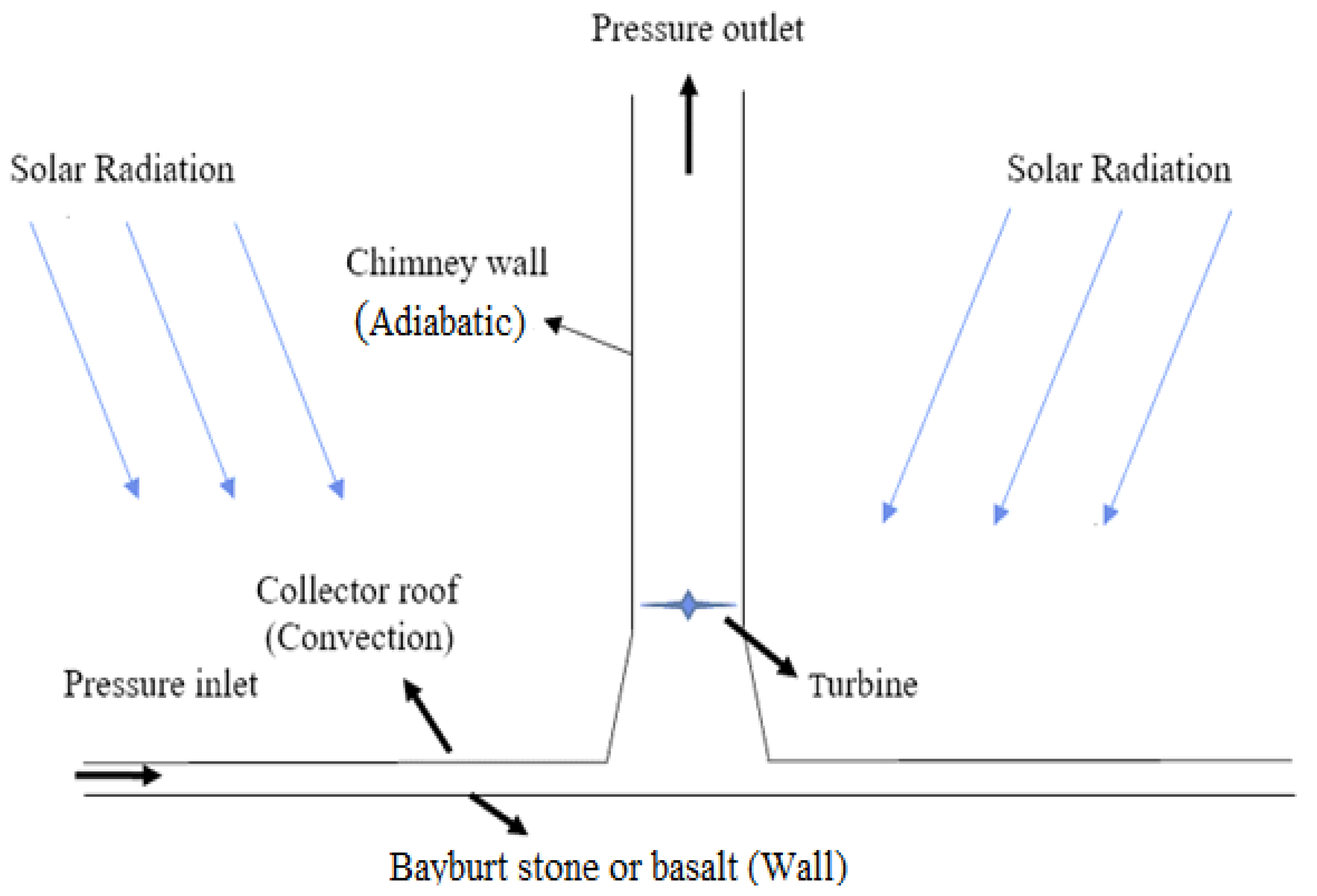
2. CFD Model and System Details

SCPPs are systems in which solar radiation is received by the collector and transferred to the system air. Not all of the solar radiation transferred to the system air is captured here; some reaches the ground. Some of this energy reaching the ground is absorbed, and some is reflected. Unlike other solar energy systems, the energy reaching the ground is stored and transferred back to the system when the effect of solar radiation decreases. For this reason, it is important to store the energy on the ground and then transfer heat to the system. In this study, the effect of the use of Bayburt stone and basalt materials, which are costly but easy to obtain, on the system in SCPP is interpreted. For this study, the geometry of the MPP was based and a CFD model was created. With the model created, the performance of the two materials at different radiation intensities and outdoor temperatures was interpreted. In the CFD model, some assumptions were made, and the solution was facilitated. These assumptions can be listed as follows:
  • The flow regime is constant in all cases, 3D and turbulent throughout the system.
  • Environmental conditions are constant during each simulation.
  • Air, which is the system fluid, is incompressible.
  • Boussinesq approximation is used for density variation.
Engineering commercial software ANSYS FLUENT was used for the CFD analyses. The continuity, energy, and momentum equations carried out through the program are as follows, respectively [28]:
· ( ρ · v ) = 0
· ( v ( ρ E + p ) ) = · ( k e f f T h j + ( μ [ ( v + v T ) 2 3 · v I ] · v ) )
( ρ · v · v ) = p + ( μ [ ( v + v T ) 2 3 · v I ] ) + ρ { g }
In SCPP, the heat transfer between the air, which is the system fluid, and that between the collector and the ground occurs by convection. Convection within the system is natural convection. The Ra number, which determines the natural convection characteristic, can be found by gravitational acceleration g, thermal expansion coefficient β, temperature change under the collector ∆T, collector height Hcoll, thermal diffusion coefficient α, and kinematic viscosity ϑ as follows:
R a = g β T H c o l l 3 α ϑ
The critical value for the Ra number is 109. For larger values, the flow is taken as turbulent [20]. The flow for the MPP is turbulent [6,8,17,18]. There are different turbulence models used in the application. In this study, the RNG turbulence model was used, which gives good results in swirling flows. The equations of the model are as follows [28]:
x i ( ρ k u i ) = x j [ α k μ e f f k x j ] + G k + G b + ρ ε Y M + S k
x i ( ρ ε u i ) = x j [ α ε μ e f f ε x j ] + C 1 ε ε k ( G k + C 3 ε G b ) C 2 ε ρ ε 2 k R e + S ε
When the experimental data of the MPP are examined, it is seen that the temperature rise in the system is maximum of 20 °C [5]. Therefore, the Boussinesq approximation is suitable for calculating the density change for the CFD study carried out, and its equation is as follows [29]:
( ρ ρ a ) g ρ a β ( T T a ) g
ρ and T in the equation represent density and temperature, respectively. The subscript α indicates the initial state. There are different uses for calculating the PO (Po) of the system. In this study, TPD (∆Pt) and volumetric flow ( Q ˙ v ) are used. The PO can be calculated by the following equation [17]:
P o = η t P t Q ˙ v
Here ηt is turbine-generator efficiency, and 0.8 is taken in the study [17]. CFD results were used to calculate the turbine pressure drop. In the pilot plant, the turbine is located 9 m above the ground [3]. The average pressure difference (Pt) in the system 9 m above the ground was found from the CFD results. The TPD rate (rt) was taken as 2/3, and the calculation was made with the following equation [17]:
P t = r t   P t
The geometric dimensions of the system were taken according to the pilot plant, and the details are presented in Table 1 [30]. When the experimental results were examined, it was understood that the temperature is almost the same during the day starting from 0.5 depth of the ground [5]. In this study, the floor thickness was taken as 2 m to better observe the temperature distribution on the ground. With the existing geometric data, a 3D model was created in the ANSYS commercial software ‘Design models.’ For the sake of economy in calculations, a 90° design was obtained by applying two-plane symmetry (YZ and XZ) in the model.
All simulations with the model were performed with the CORE i7 16 GB RAM workstation. RNG was preferred as the turbulence model in all simulations. To incorporate solar radiation into the system, the DO (discrete ordinate) solar ray tracing algorithm (SRTA) was included in the system. The pilot plant location was used for the solar beam direction vector [18]. It is a semi-transparent collector that transferred solar radiation to the system. The solar radiation passing through the collector reached the ground. Solar radiation reaching the ground was stored here. The materials used in the system are based on the pilot plant, and the details are given in Table 2.
SIMPLE was preferred for pressure and velocity discretization. The PRESTO technique was used for pressure interpolation. The Boussinesq model was considered suitable for the change in the density of the air. Details of the CFD used in the solver are given in Table 3. As convergence criteria, 10−6 for energy and radiation and 10−3 for other options were considered sufficient.
Details of the scheme and boundary conditions of the system are given in Figure 1. It is assumed that there was no pressure change at the collector inlet, which is the inlet of the system, and the chimney outlet, which is the outlet of the system.

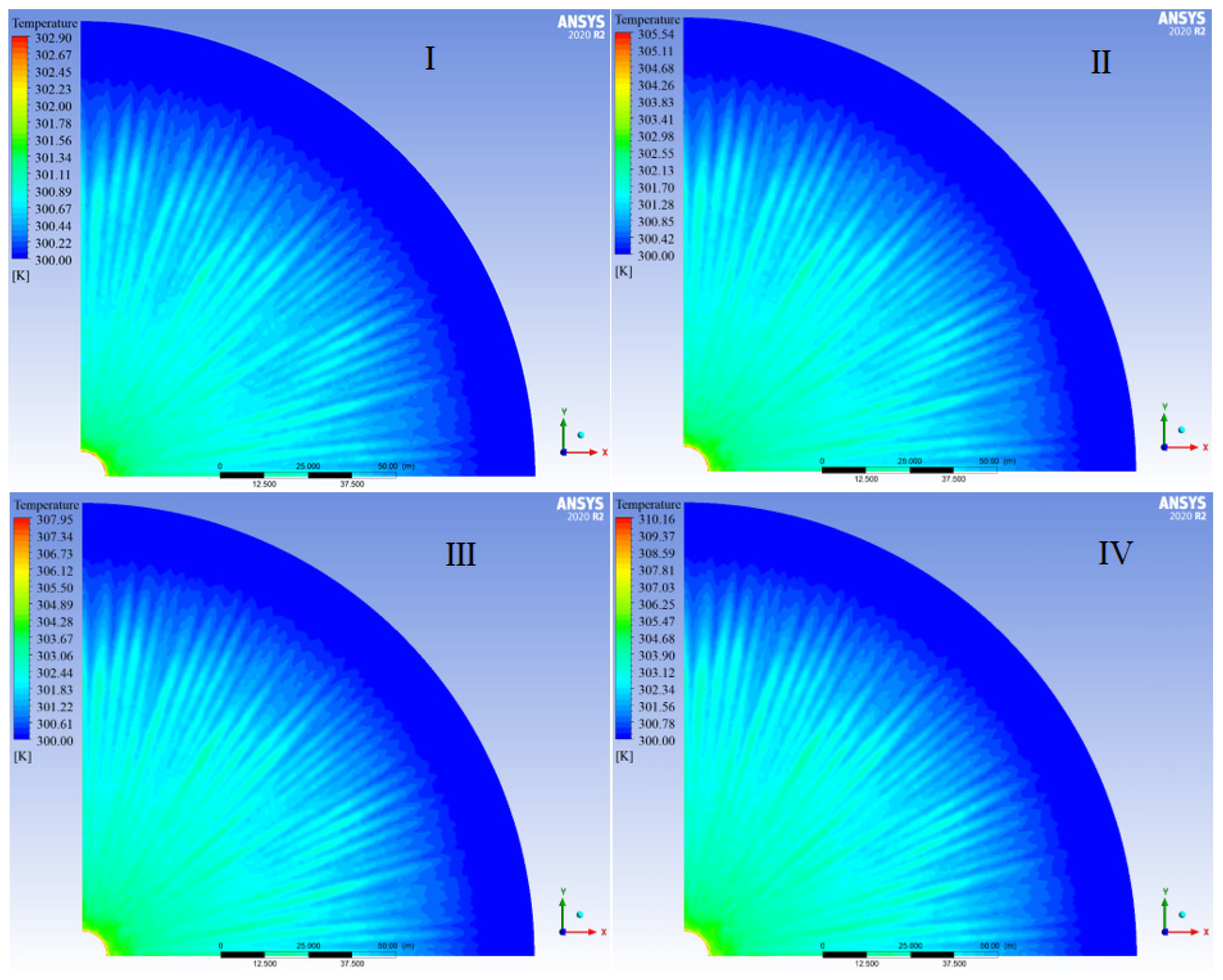
3. Results and Discussion

In the study in which the effect of Bayburt stone or basalt use on the ground on the performance of the system is examined, the analysis was carried out with the 3D model created on the basis of the pilot plant. First, a mesh-independent solution was made by considering the maximum airflow rate in the system. Details are given in Table 4. When the table is examined, it is seen that the number of 1.78 m cells is sufficient for the solution. The 3D model and mesh view are given in Figure 2. Experimental results were used to validate the CFD model after the mesh-independent solution in the conducted study. Then, the literature was also used to increase the reliability of the study. The comparison of CFD results with experimental data for solar radiation levels varying in the range of 200–800 W/m2 is given in Figure 3a. Similarly, a comparison with another study in the literature under the same conditions is given in Figure 3b. When the comparative graph is examined, it is seen that the results are compatible with the experimental data and are supported by the examples given from the studies in the literature. The same climatic conditions were observed in the experimental measurements and the comparison with the literature.
The study was carried out with a network-independent solution and a validated model. It aimed to interpret the differences in the use of Bayburt stone and basalt material that can be used as a natural storage area on the ground for the system. These materials were chosen because of their low cost and easy availability. Temperature distributions of the collector in the solar radiation range of 200–800 W/m2 for both materials at an outdoor temperature of 300 K are given in Figure 4 and Figure 5 respectively.
It is seen that the use of Bayburt stone or basalt as a storage material does not have a significant effect on the density distribution in the collector at the same outdoor temperature. When the outdoor temperature is constant, the increase in solar radiation level significantly affects the temperature in the collector. While the temperature increase in total at 200 W/m2 radiation intensity is at the level of 3 K, this value approaches 10.16 K when the radiation intensity reaches 800 W/m2. This temperature rise is similar for two different materials used on the floor.
The system is affected by the type of storage material, but not as much as by the radiation intensity. When Bayburt stone is used as the ground material, the temperature distribution in the system for two different outdoor temperatures, 290 and 300 K at 800 W/m2 constant solar radiation, is given in Figure 6. Although there is a 10 K increase in outdoor temperature, it is seen that the maximum temperature in the system has increased by about 7 K. The temperature rise in the system was investigated for two different outdoor temperatures. While an increase of 67.58 K is observed at a 290 K outdoor temperature, it is seen that the temperature increase is 64.62 K at a 300 K outdoor temperature. SCPP systems give more PO for the same radiation intensity at low outdoor temperatures [37]. More temperature rise means more kinetic energy increase in the system air. In this case, the system is expected to give more PO at a 290 K outdoor temperature. A similar situation is observed when basalt is used as a storage material on the ground. When basalt is used as the ground material, the temperature distribution in the system for an 800 W/m2 constant solar radiation and 290 and 300 K outdoor temperature is given in Figure 7. It is seen that the temperature distribution does not differ significantly for Bayburt stone and basalt materials.
It is seen that the use of different materials on the floor is not evident in the system. In this case, it is expected that the use of Bayburt stone or basalt on an SCPP floor will not affect the performance of the system. It is clear that environmental temperature and solar radiation levels are the determining factors in the performance of the system when the geometric parameters are kept constant. Since the solar radiation directly increases the energy entering the system, it affects the airflow in the system. Transferring more energy to the system air means an increase in airflow rate and, therefore, PO. Figure 8 shows the results of when Bayburt stone is used as the ground material, with the maximum velocity of the air in the system and the mass flow rate at an outdoor temperature of 300 K and solar radiation of 200–800 W/m2. It is seen that the maximum air velocity in the system, which is 8 m/s at 200 W/m2, exceeds 1.5 times when the solar radiation is 800 W/m2 and reaches 13.519 m/s. Like the airflow rate, the mass flow rate of the system also increases with the increase in solar radiation. It is seen that at a radiation intensity of 800 W/m2, the mass flow rate increases by 70% compared to 200 W/m2 and becomes 960.68 kg/s.
The POs of two different storage materials on the ground at a 300 K outdoor temperature at different levels of solar radiation are given in Table 5. When the POs are compared at 600 and 800 W/m2 radiation densities, it is seen that the POs increase for both materials. In this case, it is clear that the solar radiation level directly increases the performance of the system.
Looking at the table, it is seen that the two materials do not have a significant effect on the PO for the same radiation. It is seen that both materials can be used interchangeably.

4. Conclusions

There are many parameters that determine the performance of SCPP systems. Geometric parameters and climatic parameters have a decisive effect on the performance of the system. These parameters can be evaluated before the system is installed and used to predict possible PO. In this study, the effects of the use of Bayburt stone and basalt for energy storage on the performance of the system are interpreted. The results are evaluated by applying the DO sun ray tracing algorithm to the 3D 90-degree CFD model and RNGTM as a turbulence approach. The following bullet points can be achieved from this research:
  • DO SRTA and RNGTM give consistent results for SCPP.
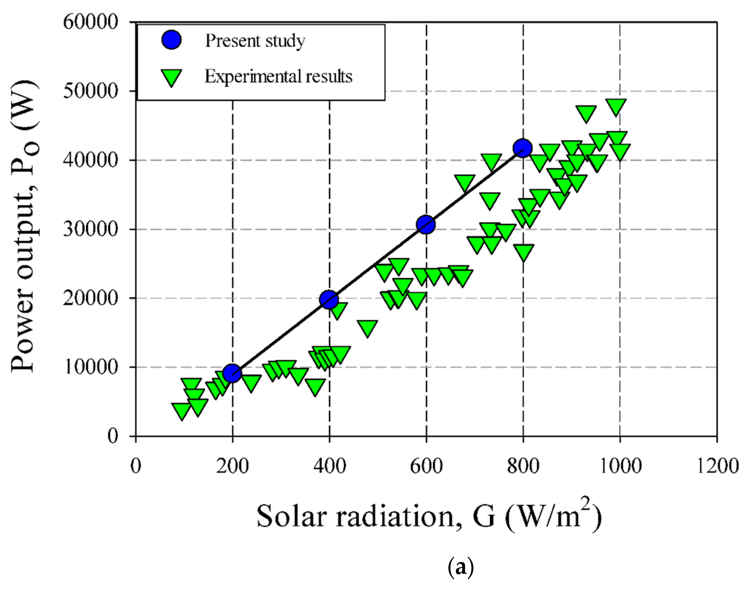
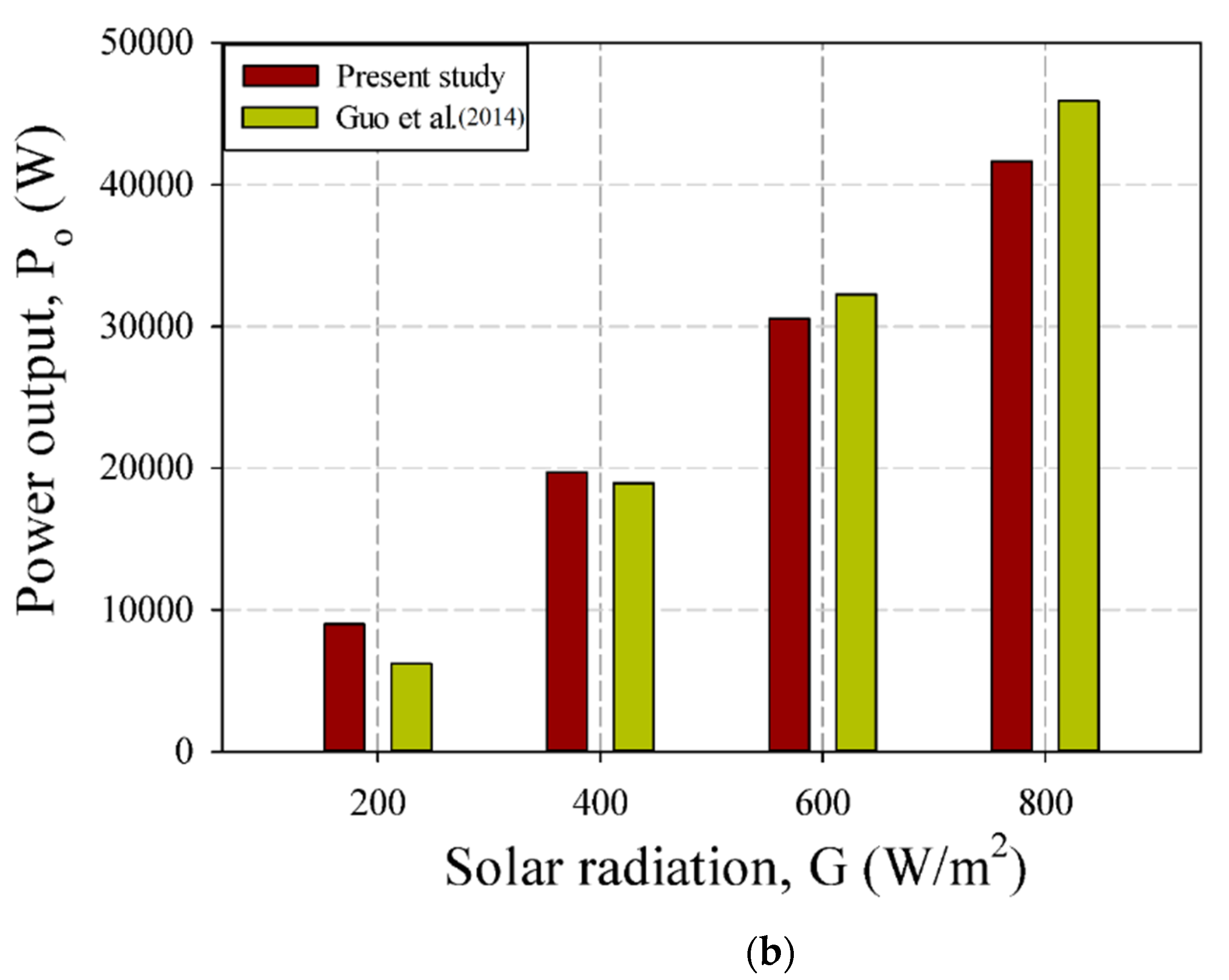
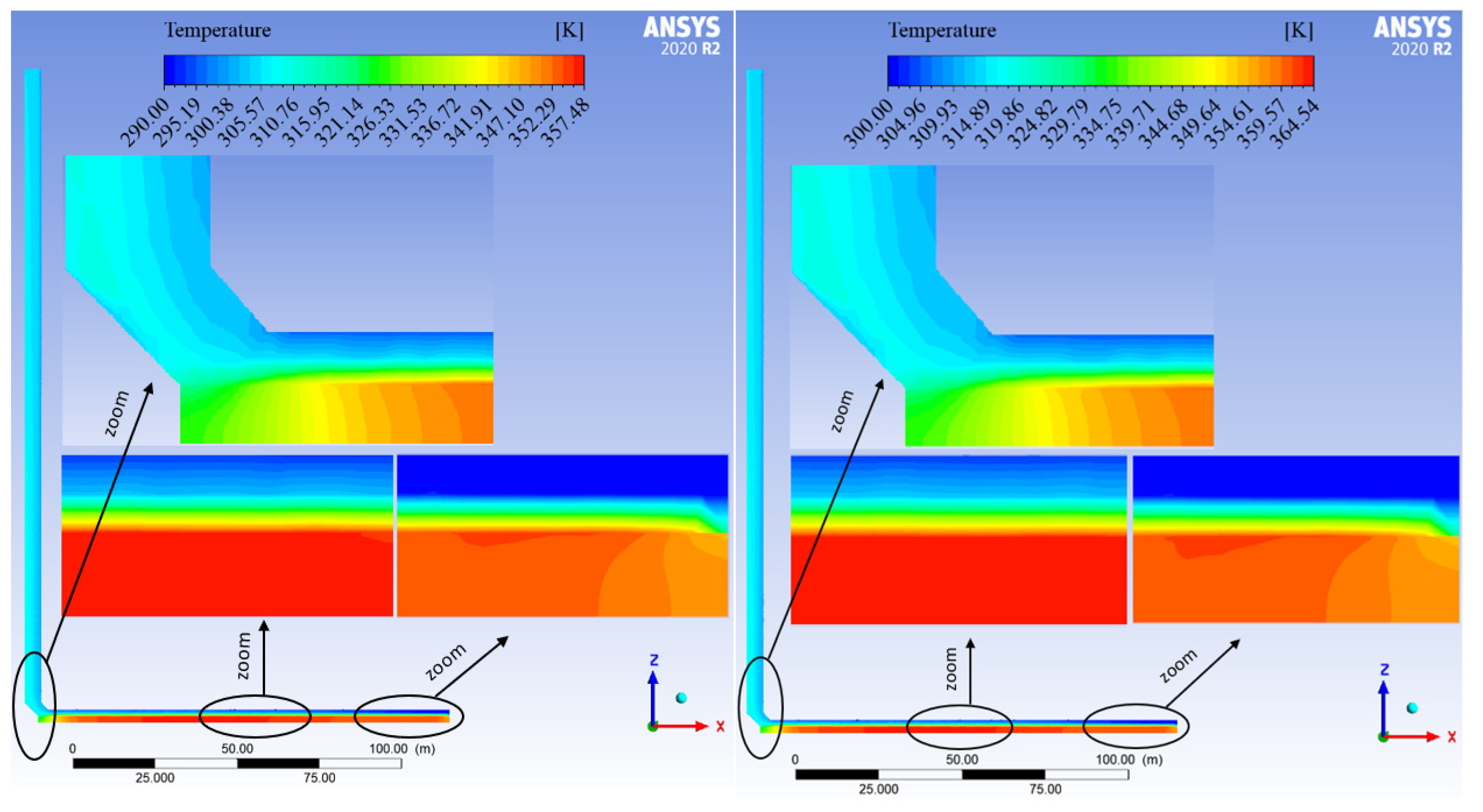
  • The level of solar radiation has a strong effect on the performance of the system.
  • The increase in outdoor temperature negatively affects the temperature rise in the system.
  • The use of Bayburt stone and basalt for energy storage on the ground shows a similar effect on the system.
  • When the storage material is Bayburt stone, the temperature rise in the system is 67.58 K at an outdoor temperature of 290 K. The temperature rise is 64.62 K when the outdoor temperature is 300 K.
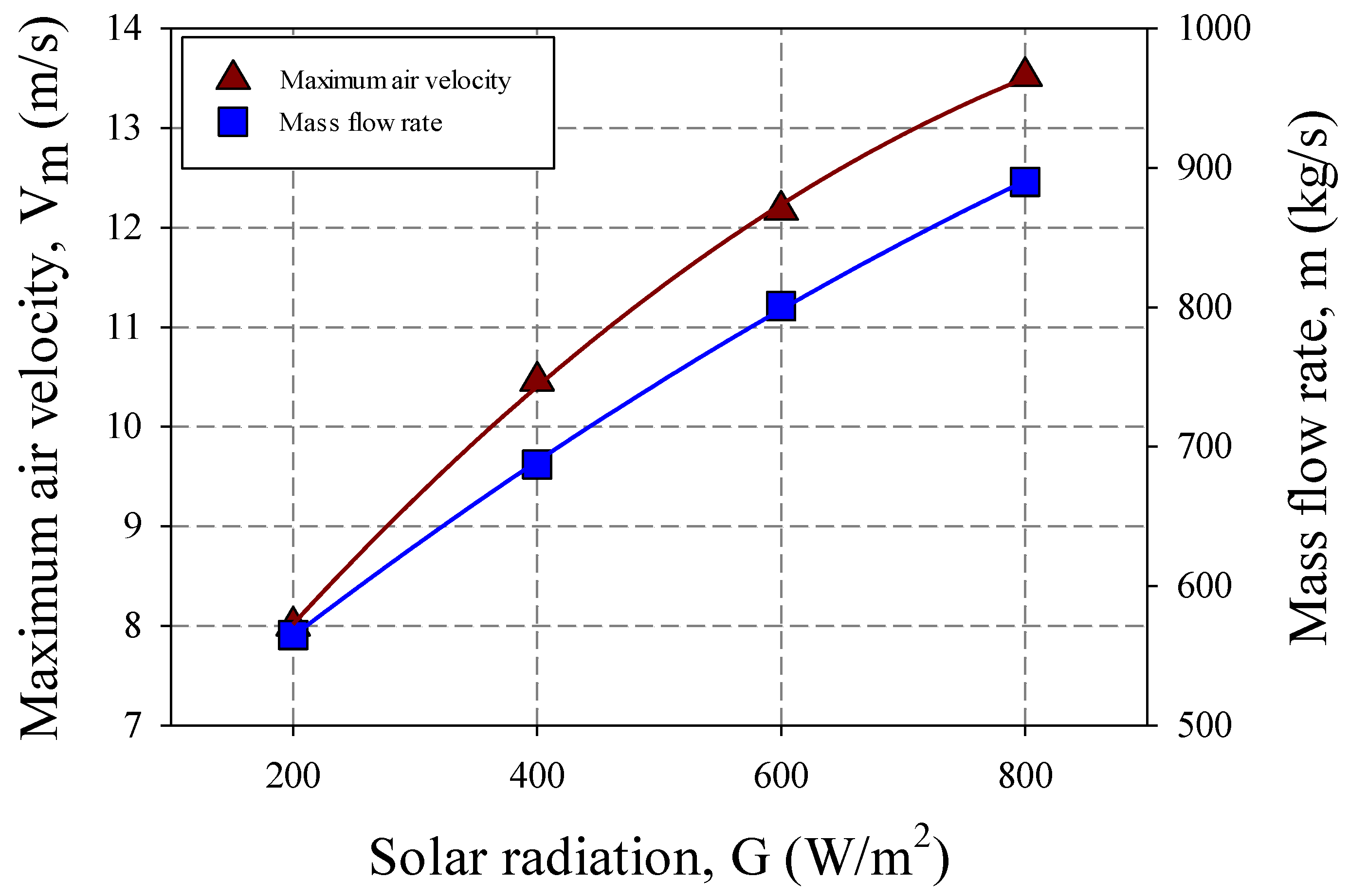
  • At solar radiation of 800 W/m2, the maximum airflow rate in the system is 13.519 m/s when the outdoor temperature is 300 K and Bayburt stone is used.
  • Solar radiation positively supports the mass flow rate of the system. Compared to 200 W/m2, at 800 W/m2, the mass flow rate increases by 70% and becomes 960.68 kg/s with Bayburt stone.

Author Contributions

Conceptualization, S.A.; Formal analysis, P.M.C.; Funding acquisition, S.A. and C.A.S.; Investigation, P.M.C. and H.S.; Methodology, P.M.C., E.C. and I.V.; Resources, S.S. and C.A.S.; Software, E.C.; Supervision, E.C.; Visualization, S.S.; Writing—original draft, E.C. and H.S.; Writing—review & editing, P.M.C., S.S. and I.V. All authors have read and agreed to the published version of the manuscript.

Funding

This research was funded by the Deanship of Scientific Research at King Khalid University (Grant No: RGP 2/32/43).

Institutional Review Board Statement

Not applicable.

Informed Consent Statement

Not applicable.

Data Availability Statement

Not applicable.

Acknowledgments

The authors extend their appreciation to the Deanship of Scientific Research at King Khalid University, Saudi Arabia for funding this work through Large Groups under Grant No: RGP 2/32/43.

Conflicts of Interest

The authors declare no conflict of interest.

Nomenclature

A c o l l Collector area (m2)
C p The specific heat of system air (J/kg·K)
g Gravity constant (m/s2)
GRadiation intensity (W/m2)
PoPO (W)
TTemp. (K)
PtPressure near turbine position (Pa)
Q ˙ Heat transf. rate (W)
Q ˙ v Volume flow rate (m3/s)
rtTPD (turbine pressure drop) rate
SCPPsSolar chimney power plant system
MPPManzanares power plant
RNGRNG turbulence model
SRTASolar ray tracing algorithm
αOutdoors
βThermal expansion coefficient (1/K)
ρDensity (kg/m3)

References

  1. Young, C.H.; Riffat, S.B.; Cuce, E. High capacity energy efficiency solar glass. In Proceedings of the Fourteenth International Conference on Sustainable Energy Technologies 2015, Nottingham, UK, 25–27 August 2015. [Google Scholar]
  2. Arnaoutakis, G.E.; Katsaprakakis, D.A. Concentrating Solar Power Advances in Geometric Optics, Materials and System Integration. Energies 2021, 14, 6229. [Google Scholar] [CrossRef]
  3. Schlaich, J.R.; Bergermann, R.; Schiel, W.; Weinrebe, G. Design of commercial solar updraft tower systems—Utilization of solar induced convective flows for power generation. J. Sol. Energy Eng. 2005, 127, 117–124. [Google Scholar] [CrossRef]
  4. Mullett, L.B. The solar chimney—Overall efficiency, design and performance. Int. J. Ambient. Energy 1987, 8, 35–40. [Google Scholar] [CrossRef]
  5. Haaf, W. Solar chimneys: Part ii: Preliminary test results from the Manzanares pilot plant. Int. J. Sustain. Energy 1984, 2, 141–161. [Google Scholar] [CrossRef]
  6. Tayebi, T.; Djezzar, M.; Gouidmi, H. 3D numerical study of flow in a solar chimney power plant system. J. Sci. Technol. 2018, 3, 55–59. [Google Scholar]
  7. Dhahri, A.; Omri, A.; Orfi, J. Numerical study of a solar chimney power plant. Res. J. Appl. Sci. Eng. Technol. 2014, 8, 1953–1965. [Google Scholar] [CrossRef]
  8. Cuce, E.; Sen, H.; Cuce, P.M. Numerical performance modelling of solar chimney power plants: Influence of chimney height for a pilot plant in Manzanares, Spain. Sustain. Energy Technol. Assess. 2020, 39, 100704. [Google Scholar] [CrossRef]
  9. Hu, S.; Leung, D.Y.; Chan, J.C. Impact of the geometry of divergent chimneys on the power output of a solar chimney power plant. Energy 2017, 120, 1–11. [Google Scholar] [CrossRef]
  10. Cuce, E.; Cuce, P.M. Performance assessment Energy Research Journal of solar chimneys: Part 2—Impacts of slenderness value and collector slope on power output. Energy Res. J. 2019, 10, 20–26. [Google Scholar] [CrossRef]
  11. Sen, H.; Cuce, E. Dynamic pressure distributions in solar chimney power plants: A numerical research for the pilot plant in Manzanares, Spain. WSSET Newsl. 2020, 12, 2. [Google Scholar]
  12. Li, J.Y.; Guo, P.H.; Wang, Y. Effects of collector radius and chimney height on power output of a solar chimney power plant with turbines. Renew. Energy 2012, 47, 21–28. [Google Scholar] [CrossRef]
  13. Karimipour Fard, P.; Beheshti, H. Performance enhancement and environmental impact analysis of a solar chimney power plant: Twenty-four-hour simulation in climate condition of isfahan province, Iran. Int. J. Eng. 2017, 30, 1260–1269. [Google Scholar]
  14. Rajput, S.R.; Nigam, D.S.R.; Sen, D.M. Integrated solar heat and wind power plant: Design and performance. Int. J. Eng. Sci. Manag. 2017, 7, 407–423. [Google Scholar]
  15. Ming, T.; de Richter, R.K.; Meng, F.; Pan, Y.; Liu, W. Chimney shape numerical study for solar chimney power generating systems. Int. J. Energy Res. 2013, 37, 310–322. [Google Scholar] [CrossRef]
  16. Das, P.; Chandramohan, V.P. 3D numerical study on estimating flow and performance parameters of solar updraft tower (SUT) plant: Impact of divergent angle of chimney, ambient temperature, solar flux and turbine efficiency. J. Clean. Prod. 2020, 256, 120353. [Google Scholar] [CrossRef]
  17. Cuce, E.; Saxena, A.; Cuce, P.M.; Sen, H.; Guo, S.; Sudhakar, K. Performance assessment of solar chimney power plants with the impacts of divergent and convergent chimney geometry. Int. J. Low-Carbon Technol. 2021, 16, 704–714. [Google Scholar] [CrossRef]
  18. Hassan, A.; Ali, M.; Waqas, A. Numerical investigation on performance of solar chimney power plant by varying collector slope and chimney diverging angle. Energy 2018, 142, 411–425. [Google Scholar] [CrossRef]
  19. Weli, R.B.; Atrooshi, S.A.; Schwarze, R. Investigation of the performance parameters of a sloped collector solar chimney model–An adaptation for the North of Iraq. Renew. Energy 2021, 176, 504–519. [Google Scholar] [CrossRef]
  20. Cuce, E.; Cuce, P.M.; Sen, H.; Sudhakar, K.; Berardi, U.; Serencam, U. Impacts of Ground Slope on Main Performance Figures of Solar Chimney Power Plants: A Comprehensive CFD Research with Experimental Validation. Int. J. Photoenergy 2021, 2021, 6612222. [Google Scholar] [CrossRef]
  21. Cuce, P.M.; Cuce, E.; Sen, H. Improving electricity production in solar chimney power plants with sloping ground design: An extensive CFD research. J. Sol. Energy Res. Updates 2020, 7, 122–131. [Google Scholar] [CrossRef]
  22. Attig-Bahar, F.; Sahraoui, M.; Guellouz, M.S.; Kaddeche, S. Effect of the ground heat storage on solar chimney power plant performance in the South of Tunisia: Case of Tozeur. Sol. Energy 2019, 193, 545–555. [Google Scholar] [CrossRef]
  23. Sedighi, A.A.; Deldoost, Z.; Karambasti, B.M. Effect of thermal energy storage layer porosity on performance of solar chimney power plant considering turbine pressure drop. Energy 2020, 194, 116859. [Google Scholar] [CrossRef]
  24. Ming, T.; Liu, W.; Pan, Y.; Xu, G. Numerical analysis of flow and heat transfer characteristics in solar chimney power plants with energy storage layer. Energy Convers. Manag. 2008, 49, 2872–2879. [Google Scholar] [CrossRef]
  25. Xu, G.; Ming, T.; Pan, Y.; Meng, F.; Zhou, C. Numerical analysis on the performance of solar chimney power plant system. Energy Convers. Manag. 2011, 52, 876–883. [Google Scholar] [CrossRef]
  26. Senbeto, M. Numerical simulations of solar chimney power plant with thermal storage. Int. J. Eng. Res. Technol. IJERT 2020, 9, 103–106. [Google Scholar]
  27. Guo, P.; Wang, Y.; Li, J.; Wang, Y. Thermodynamic analysis of a solar chimney power plant system with soil heat storage. Appl. Therm. Eng. 2016, 100, 1076–1084. [Google Scholar] [CrossRef]
  28. ANSYS FLUENT Theory Guide. November 2013. Available online: http://www.pmt.usp.br/academic/martoran/notasmodelosgrad/ANSYS%20Fluent%20Theory%20Guide%2015.pdf (accessed on 11 May 2022).
  29. Tingzhen, M.; Wei, L.; Guoling, X.; Yanbin, X.; Xuhu, G.; Yuan, P. Numerical simulation of the solar chimney power plant systems coupled with turbine. Renew. Energy 2008, 33, 897–905. [Google Scholar] [CrossRef]
  30. Haaf, W.; Friedrich, K.; Mayr, G.; Schlaich, J. Solar chimneys part I: Principle and construction of the pilot plant in Manzanares. Int. J. Sol. Energy 1983, 2, 3–20. [Google Scholar] [CrossRef]
  31. Pandey, M.; Padhi, B.N.; Mishra, I. Performance analysis of a waste heat recovery solar chimney for nocturnal use. Eng. Sci. Technol. Int. J. 2021, 24, 1–10. [Google Scholar] [CrossRef]
  32. Abdelmohimen, M.A.; Algarni, S.A. Numerical investigation of solar chimney power plants performance for Saudi Arabia weather conditions. Sustain. Cities Soc. 2018, 38, 1–8. [Google Scholar] [CrossRef]
  33. Cuce, P.M. Box type solar cookers with sensible thermal energy storage medium: A comparative experimental investigation and thermodynamic analysis. Sol. Energy 2018, 166, 432–440. [Google Scholar] [CrossRef]
  34. Chen, W. Analysis of heat transfer and flow in the solar chimney with the sieve-plate thermal storage beds packed with phase change capsules. Renew. Energy 2020, 157, 491–501. [Google Scholar] [CrossRef]
  35. Setareh, M. Comprehensive mathematical study on solar chimney powerplant. Renew. Energy 2021, 175, 470–485. [Google Scholar] [CrossRef]
  36. Guo, P.H.; Li, J.Y.; Wang, Y. Numerical simulations of solar chimney power plant with radiation model. Renew. Energy 2014, 62, 24–30. [Google Scholar] [CrossRef]
  37. Cuce, E.; Cuce, P.M.; Carlucci, S.; Sen, H.; Sudhakar, K.; Hasanuzzaman, M.; Daneshazarian, R. Solar chimney power plants: A review of the concepts, designs and performances. Sustainability 2022, 14, 1450. [Google Scholar] [CrossRef]
Figure 1. Schematic view and boundary conditions of the system.
Sustainability 14 10960 g001
Figure 2. Model and mesh view.
Sustainability 14 10960 g002
Figure 3. (a) Comparison of CFD results at different radiation with experimental data [3]. (b) Comparison of CFD results at different radiations with literature data [36].
Sustainability 14 10960 g003aSustainability 14 10960 g003b
Figure 4. When Bayburt stone is used as the ground material, the temperature distribution in the collector is 200, 400, 600, and 800 W/m2 (for 300 K outdoor temperature) in numerical order (IIV).
Sustainability 14 10960 g004
Figure 5. When basalt is used as the ground material, the temperature distribution in the collector is 200, 400, 600, and 800 W/m2 (for 300 K outdoor temperature) in numerical order (IIV).
Sustainability 14 10960 g005
Figure 6. Temperature distribution in the system at 290 and 300 K for Bayburt stone storage material.
Sustainability 14 10960 g006
Figure 7. Temperature distribution in the system at 290 and 300 K for basalt storage material.
Sustainability 14 10960 g007
Figure 8. Maximum air velocity and mass flow rate when Bayburt stone is used as storage material for outdoor temperature of 300 K.
Sustainability 14 10960 g008
Table 1. Design details of the reference plant in Manzanares [30].
Design AspectValue
Coll. height1.85 m
Coll. diameter244.0 m
Chim. diameter10.16 m
Chim. height194.6 m
Ground layer thick2 m
Table 2. Material characteristics which are utilized in the CFD model [31,32,33,34].
FeatureGlassBayburt StoneBasaltChimney
Dens. (kg∙m−3)2700237026952100
Thermal cond. (W∙m−1K−1)0.780.591.711.4
Specific heat (J∙kg−1K−1)840714.4920880
Transmissivity0.9Non-transp.Non-transp.Non-transp.
Absorptivity0.040.80.80.6
Index of refraction1111
Emissivity0.10.90.90.71
Thickness (m)0.004220.00125
Table 3. Environmental conditions and details of CFD [8,35].
Incoming Solar Intensity (W∙m−2)600–800
Outdoor pressure (Pa)92,930
Outdoor temperature (K)300
Outdoor air dens. (kg/m3)1.0795
Gravity const.(m/s2)9.81
Thermal cond. (W/mK)0.0264
Gas constant (J/kgK)287
Kin. viscosity (m/s2)1.8 × 10−5
Heat capacity (J/kgK)1006.24
TPD ratio2/3
Stefan Boltzmann const. (W/m2K4)0.5667 × 10−7
Table 4. Quality of mesh structure in the CFD model.
Cell No.Element Size (m)Max Air Velocity (m/s)% Difference
1.08 m113.56-
1.43 m0.88513.550.07
1.78 m0.813.5460.03
Table 5. POs of different ground materials at different levels of solar radiation.
Ground Storage MaterialSolar Radiation, G (W/m2)PO, Po (W)
Bayburt stone80041,397
60030,184
40019,067
2008430
Basalt80041,427
60030,185
40019,103
2008451
Publisher’s Note: MDPI stays neutral with regard to jurisdictional claims in published maps and institutional affiliations.

