Article

Dynamic Mechanical Behaviors and Failure Mechanism of Lignite under SHPB Compression Test

1
State Key Laboratory of Coal Resources and Safe Mining, China University of Mining and Technology (Beijing), Beijing 100083, China
2
School of Mechanics and Civil Engineering, China University of Mining and Technology (Beijing), Beijing 100083, China
*
Author to whom correspondence should be addressed.
Sustainability 2022, 14(17), 10528; https://doi.org/10.3390/su141710528
Submission received: 31 July 2022 / Revised: 19 August 2022 / Accepted: 22 August 2022 / Published: 24 August 2022
(This article belongs to the Special Issue Deep Mining Engineering in Sustainability)

Abstract

:
There is an obvious impact effect of on-site blasting on the slope coal mass of open-pit mines, so it is of great significance to study the dynamic mechanical response characteristics of coal rock for slope stability control. In this paper, first, the mineral composition and microstructure of lignite from open-pit mine are analyzed, and it is found that the content of non-organic minerals in lignite such as clay accounts for more than 24.40%; meanwhile, the rock sample has obvious horizontal bedding characteristics and mainly micro pores and transition pores inside; further, there are obvious banded areas with high water content in the rock, which has the same extending direction as the beddings. Based on the SHPB test system, the dynamic compression tests of lignite with different impact velocities are carried out. The results show that there is a significant hardening effect caused by the increase of strain rate on the dynamic mechanical parameters of rock samples, and the stress–strain curve has obvious “double peak” characteristics; meanwhile, the macroscopic crack of the rock appears at the first stress peak and disappears after further compression until the interlayer fracture occurs; further, the fracture fractal dimension of lignite increases linearly with the impact velocity, revealing that the fragmentation of rock samples increases gradually. In addition, with the increase of impact velocity, the input energy and dissipated energy of rock samples increase linearly, while the elastic property increases slowly and at a low level. The bedding characteristics of lignite and the wave impedance difference between the layers cause the high-reflection phenomenon in the process of stress-wave propagation, and then produce the obvious tensile stress wave in the rock sample, which finally results in the interlayer fracture failure of the rock.

1. Introduction

Blasting technology is often used to crush rock mass in modern large-scale engineering construction, such as tunnel excavation, open-pit mining, and so on [1,2,3]. Especially for the open-pit mining, blasting makes the adjacent coal mass subjected to the impact compression by the high-strain rate, resulting in instantaneous cracking and local possibly crushing of the rock mass, finally causing disasters, such as rock burst, landside, etc., [4,5]. It is noted that the coal-rock mass of the open-pit slope bears the influence of blasting vibration perennially [6], which has a great influence on safety mining, so it is of great significance to study the mechanical behavior and failure mechanism of coal rocks under different impact velocities for the control of the slope stability.
Different impact velocities cause differences in the internal strain rates of the rock, and the scholars have similar standards for the division of strain rates [5,7,8], including low strain rate (10−5~10−2 s−1), medium strain rate (10−2~102 s−1), high strain rate (102~104 s−1), and ultra-high strain rate (greater than 104 s−1). Moreover, many scholars have studied the dynamic response characteristics of rocks under different strain rates with experimental methods including drop-weight impact test [9,10], SHPB impact test [11,12,13,14], and plate impact test [15,16], etc. In recent years, many scholars have found that the SHPB test has very a high reliability in obtaining rock mechanical behavior under high strain rates [11,17]. Wang et al. [18] carried out impact compression tests of sandstone processed by freeze–thaw and thermal shock and found that the dynamic mechanical behavior changes of sandstone treated by the two methods had a significant rate effect. Gong et al. [19] carried out triaxial impact compression tests on sandstone based on the SHPB test system, and found that the dynamic uniaxial and triaxial strength of sandstone increased logarithmically with the increase of strain rate. Zhao et al. [20] analyzed the strain rate effect of rock fragmentation under the impact compression test and used fractal theory to describe the crushing characteristics of the rock. Gong et al. [21] analyzed the energy evolution characteristics of granite under dynamic impact and found that the input energy increased with the strain rate, which was similar to the change of rock fragmentation degree, and there was critical input energy for rock failure. Lignite, as a kind of rock sample with significant bedding characteristics usually obtained from open-pit mines [22], has been rarely studied on the mechanical response characteristics under dynamic impact.
Mineral composition and microstructure have a significant influence on the dynamic and static mechanical behavior of the rock [23,24,25,26]. Prikryl [27] found through experiments that the change of rock compressive strength could be described by the quantitative evolution of microstructure, and the particle size was the main factor controlling the change of rock strength. Ma et al. [28] carried out uniaxial compression tests of tuff with different drying time, and found that the rock fracture surface was mostly along the edge of crystal pyroclast, and transgranular failure was occasionally seen. Ju et al. [29] studied the influence of mineral composition and porous structure on the dynamic impact characteristics of rocks with the help of CT imaging technology. Yu et al. [30] carried out the impact compression test of chemically corroded NSCB limestone samples combined with the NMR test, and found that the chemical corrosion caused damage to the internal structure of the rock, thereby affecting the dynamic mechanical properties of rocks. The bedding structure has a great influence on the dynamic and static failure characteristics of the rock. In view of this, Liu et al. [31] and Zhao et al. [32] conducted dynamic and static mechanical tests of the rock, and found that the influence of bedding effect on mechanical properties is more significant in the static test; meanwhile, with the increase of dynamic loading velocity, the influence of beddings on crack morphology gradually decreased. Lignite had a low metamorphic degree, contains more impurities, and had significant bedding characteristics [22], which has been considered rarely in the studies on its dynamic mechanical properties.
In this paper, the mineral composition and microstructure characteristics of lignite samples were analyzed by XRD-XRF test, thin slice analysis and NMR detection techniques. Then, based on the SHPB test system, the dynamic compression tests of lignite under different impact velocities were carried out, and the strain rate effect on dynamic mechanical parameters of lignite samples was analyzed. Meanwhile, with the help of the high-speed camera, the progressive failure process of rock samples was analyzed, and the evolution law of the lignite fragmentation was explored based on the fractal theory. Finally, based on the microstructure characteristics of lignite samples, the interlayer fracture mechanism of lignite was discussed.

2. Methology

2.1. Sample Preparation

The rock samples required for the test were open-pit lignite taken from Inner Mongolia, China. Furthermore, the large lignite blocks obtained in situ were packaged and transported to the laboratory; then, the cylindrical sample with a height of 45 mm and a diameter of 50 mm was processed after drilling, cutting, grinding procedures, and the size, the processing accuracy of the rock sample met the test standard [23]. In addition, the rock samples with non-obvious appearance defects were selected by the acoustic velocity measurement, and the samples with a similar wave velocity were utilized in the test. Meanwhile, the lignite was ground by the agate grinding dish and processed into powder solid with a particle size of less than 48 um for the identification of mineral composition. Finally, the prepared cylindrical lignite sample was reprocessed to make thin slices from the radial and axial location of the rock with a thickness of 0.3 mm for the microstructure observation.

2.2. Test System

Based on the split Hopkinson pressure bar (SHPB) test system, the dynamic mechanical behavior of lignite under different impact velocities was tested in this paper, and the test system was mainly composed of a power device, stricken bar, incident bar, transmitted bar, buffer bar, damper, and data acquisition system. It was required to meet two assumptions before the SHPB test [13,14,17,29], including the assumption of uniform stress and the assumption of one-dimensional stress wave. Based on this, the processing length of the incident bar, transmitted bar, and buffer bar was 3 m, 3 m, and 1.5 m respectively; meanwhile, the “spindle shaped” bullet was used to complete the impact test; finally, to reduce the dispersion effect at the end of the bar during impact test, a shaper was set at the front end of the incident bar. The DH8302 laser velocimeter with the accuracy of 10−5 m/s was used to record the impact velocity of the bullet during the test, and the Vision Research/V410L ultra-high-speed digital camera with the sampling frequency of 57,000 fps was used to monitor the instantaneous failure of lignite samples. Meanwhile, the dynamic strain gauge was pasted at the same position in the middle of the incident bar and the transmitted bar, which was connected to the high-speed dynamic acquisition instrument to monitor the micro strain on the surface of the bar. In order to clearly observe the progressive failure of rock samples during the impact test, the black–white speckle was made on the side of the rock before the test. The impact compression test system is shown in Figure 1.
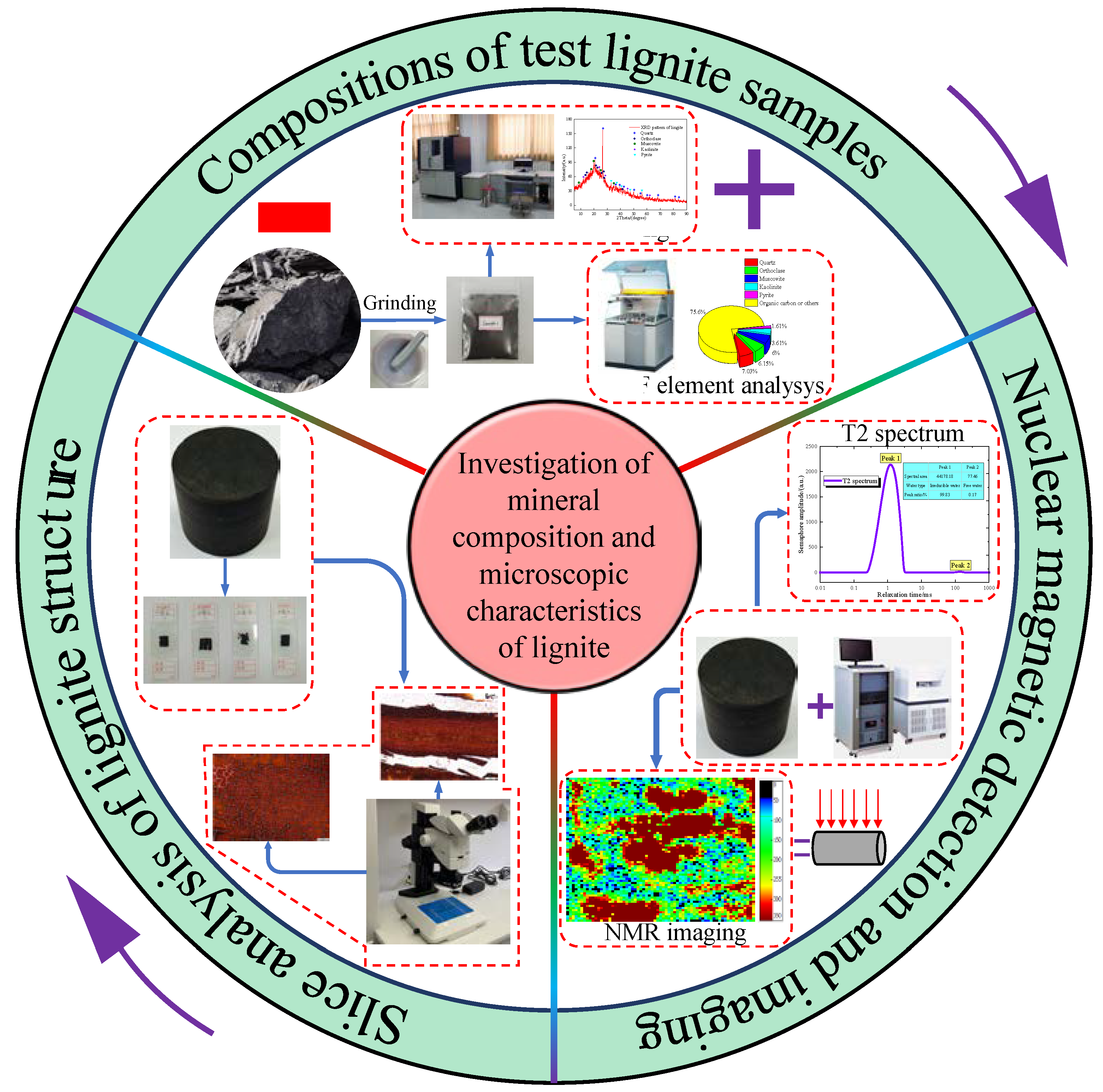
In addition to dynamic mechanical tests, this paper also focused on the mineral composition and microstructure of the lignite. Consequently, the mineral composition analysis equipment was the D/max 2500 PC X-ray diffractometer and the Panalytical Axios series X-ray fluorescence spectrometer respectively. In addition, the Zeiss research level optical microscope was used to observe the microstructure of thin slices, and the MesoMR23-060H-I nuclear magnetic resonance detection system was used for testing and imaging analysis of the lignite. The test arrangement is shown in Figure 2.

2.3. Test Method

The split Hopkinson pressure bar (SHPB) test system used in this paper provided power by compressing the nitrogen, and the nitrogen pressure could be adjusted automatically to control the impact velocity of bullets. In order to study the influence of different impact velocities on the dynamic mechanical behavior of lignite, the impact pressure was set from 0.1 MPa to 0.3 MPa, and the impact velocity was controlled by adjusting the distance between the bullet and the stricken bar. In addition, the test impact velocity was recorded from 4.26 m/s to 14.04 m/s, which is coincident with the vibration velocity of slope rock mass measured on site, and seven different impact velocities were obtained, named A~G group respectively. Meanwhile, there were three samples in each group, which contributed to a total of twenty-one lignite samples. Before the test, the rock sample was fixed between the incident bar and the transmitted bar, and the end face of the rock sample was smeared with Vaseline to reduce the friction; at the same time, the lens of the high-speed camera was aligned to the optimal observation surface. Then the power system started to work and pressurize until the set pressure was reached, and the operator pressed the test switch for the impact test with the monitoring by the high-speed camera synchronously.
For the analysis of the microstructure of lignite, placed the thin slice sample at the objective platform of the microscope, continuously observed by adjusting the magnification, constantly converted the observation area to obtain the optimal position, and repeated the steps to obtain the radial and axial microstructure characteristics of the rock sample. The cylindrical rock sample was immersed for four hours by vacuum and water saturation method before the NMR test; then the rock sample was placed horizontally on the test bench, and the T2 spectrum test and nuclear magnetic imaging test were carried out simultaneously.

3. Composition and Microstructure

3.1. Composition

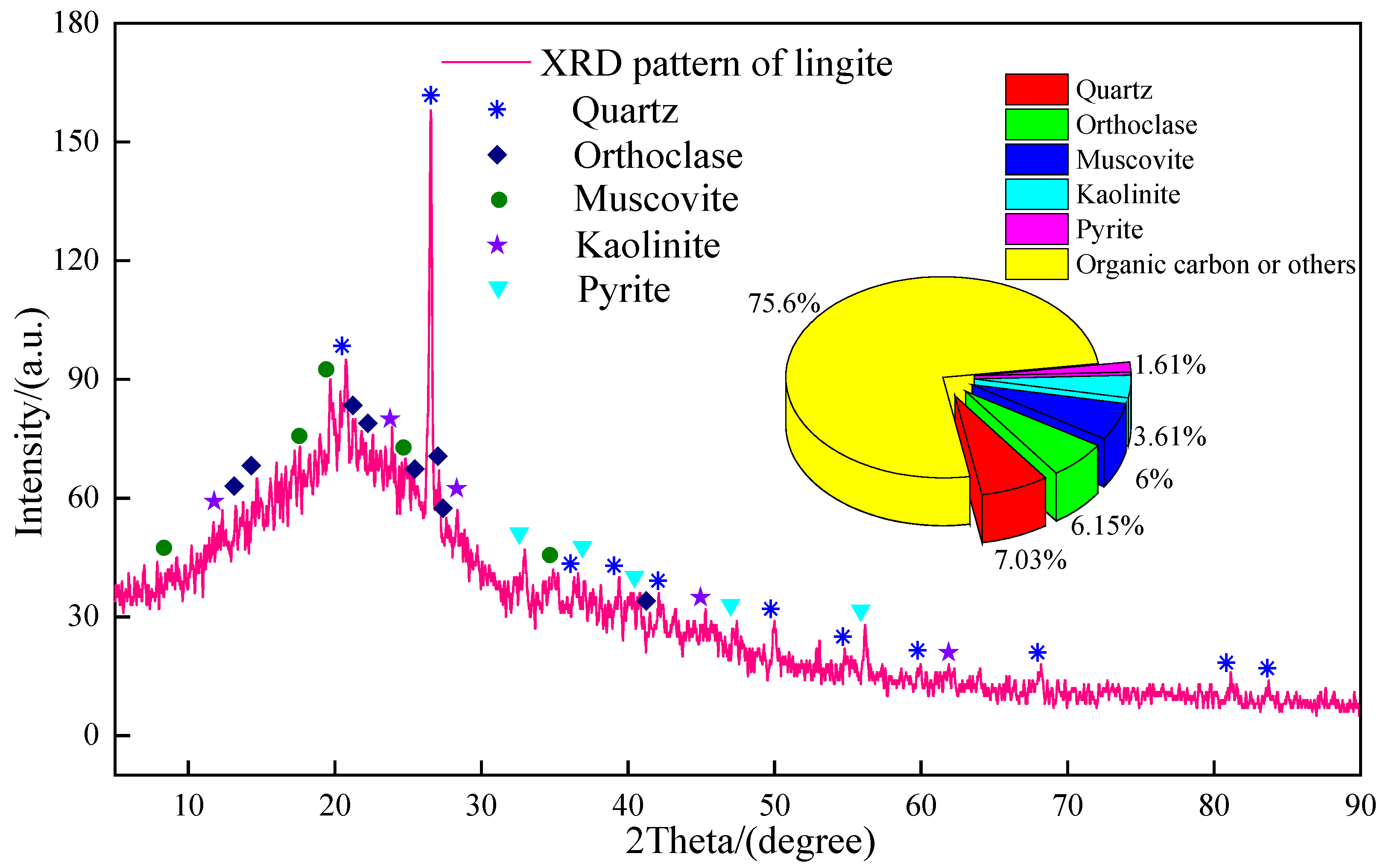
The material composition and the proportion of each mineral content of lignite were obtained by XRD and XRF tests, as shown in Figure 3.
As shown in Figure 4, lignite contains many minerals such as quartz, orthoclase, muscovite, kaolinite, and pyrite, with a total content of 24.40%; importantly, kaolinite is a clay mineral, and muscovite belongs to the illite, which is a transition mineral from the montmorillonite group minerals and a potential clay mineral component. Therefore, the high-water content characteristic of lignite is caused by low metamorphic degree and low humification degree, and strong water absorption of clay minerals [22]. The research showed that during the impact compression test, there was a mutual process between different mineral particles in the rock sample, and the high-strength rock particles would embed or crush the low-strength rock matrix [26].

3.2. Thin Slice Analysis

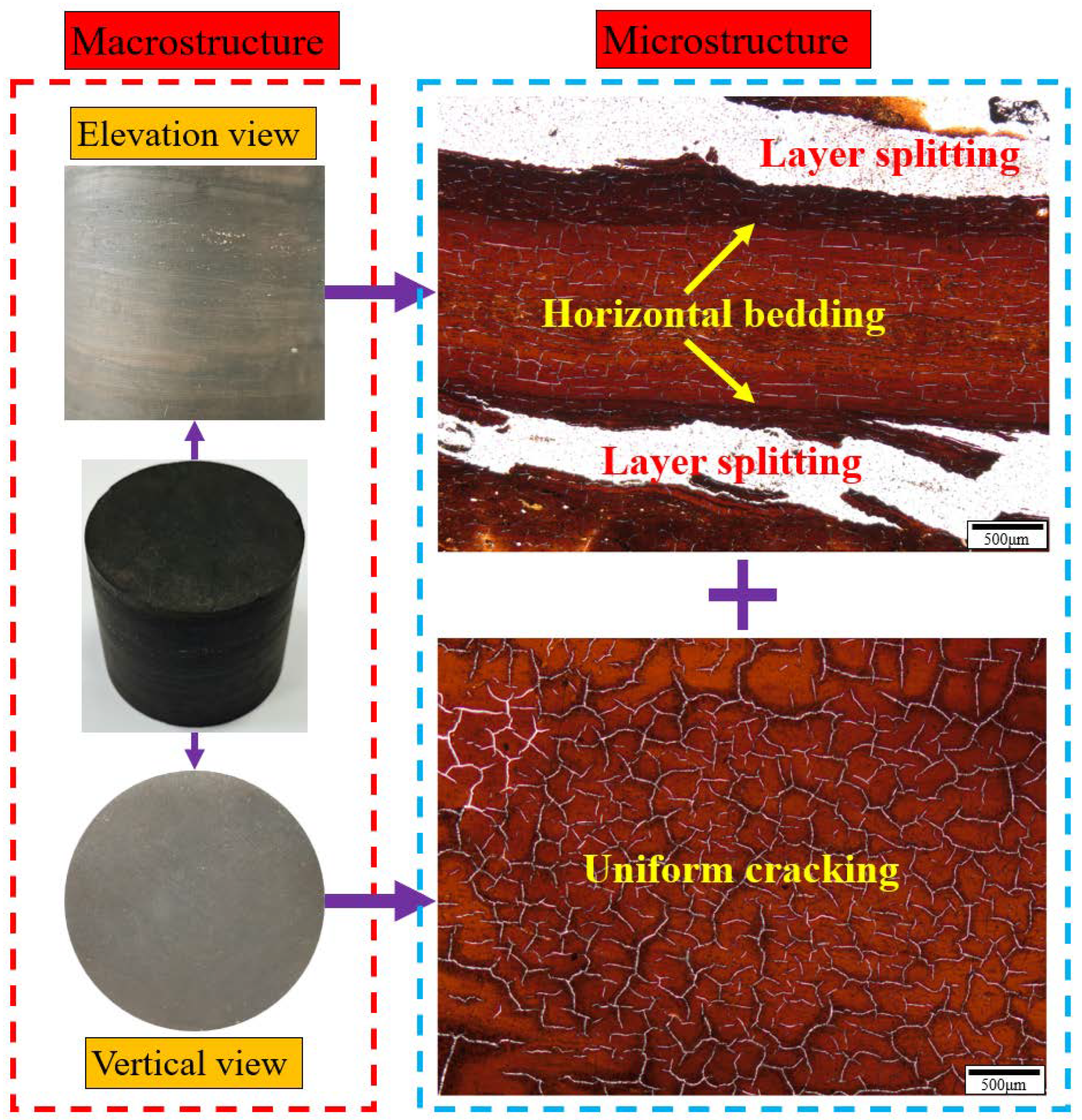
Through the microscopic test, the analysis of radial and axial slices of lignite samples, the microstructure characteristics of lignite were obtained, as shown in Figure 4.
It can be seen from Figure 4 that in terms of macrostructure, the horizontal bedding characteristics of the rock sample are significant; meanwhile, the radial end face is flat and smooth, which has no significant structural characteristics. In terms of microstructure, there are obvious stratification characteristics in the axial direction of rock samples and obvious differences in the color of beddings in the rock. During the processing of thin slice samples, it is found that rock samples always present obvious cracks along the interlayer, which proves that the strength of interlayer materials is low and easy to separate. Radial processed slices have no obvious bedding characteristics, but there are a large number of uniformly distributed cracks which are caused by the dehydration of high-water content lignite at the normal temperature [33,34]. In conclusion, lignite samples have obvious horizontal bedding structures, and their mechanical behavior under dynamic impact needs to be further studied.

3.3. NMR Analysis

The cylindrical lignite samples were tested and analyzed by the NMR detection system, and the relaxation time T2 spectrum of lignite and the NMR imaging characteristics were obtained, as shown in Figure 5.
According to Figure 5a, the T2 spectrum of lignite has only two characteristic peaks, in which the intensity of the first peak is higher than 2000, and that in the second peak is only 80; meanwhile, the first peak corresponds to bound water with the peak area accounting for 99.83%, and the second peak corresponds to free water with the peak area accounting for 0.17%. Figure 5b shows the signal characteristics of water content distribution in lignite samples, and the signal intensity corresponds to the water content. The results show that a large amount of water is evenly distributed in the whole lignite, but there are also many horizontal banded areas with high water content, which further proves that there is a difference in the material composition between the horizontal beddings; meanwhile, the local high-water content material is relatively soft, which is more prone to compressive deformation or tensile failure under axial stress conditions.
The T2 spectrum of NMR relaxation time can reflect the pore structure in the rock sample [30]. Yao et al. [35] divided the characteristic peak of T2 < 2.5 ms into micropores and transition pores, and the characteristic peak of T2 > 100 ms into macropores and microcracks. It can be seen from Figure 5a that the lignite rock sample contains a large number of micropores and transition pores, which is opposite to the content of macropores and microcracks. The results show that the internal defect of lignite samples is not obvious; meanwhile, due to the joint obstruction of the Jamin effect and capillary force, it is difficult for the external water sources to enter the rock [36]; therefore, the water absorption of the rock is not high in the process of vacuum water saturation treatment before the NMR test.

4. Dynamic Mechanical Behaviors

4.1. Calculation Criteria

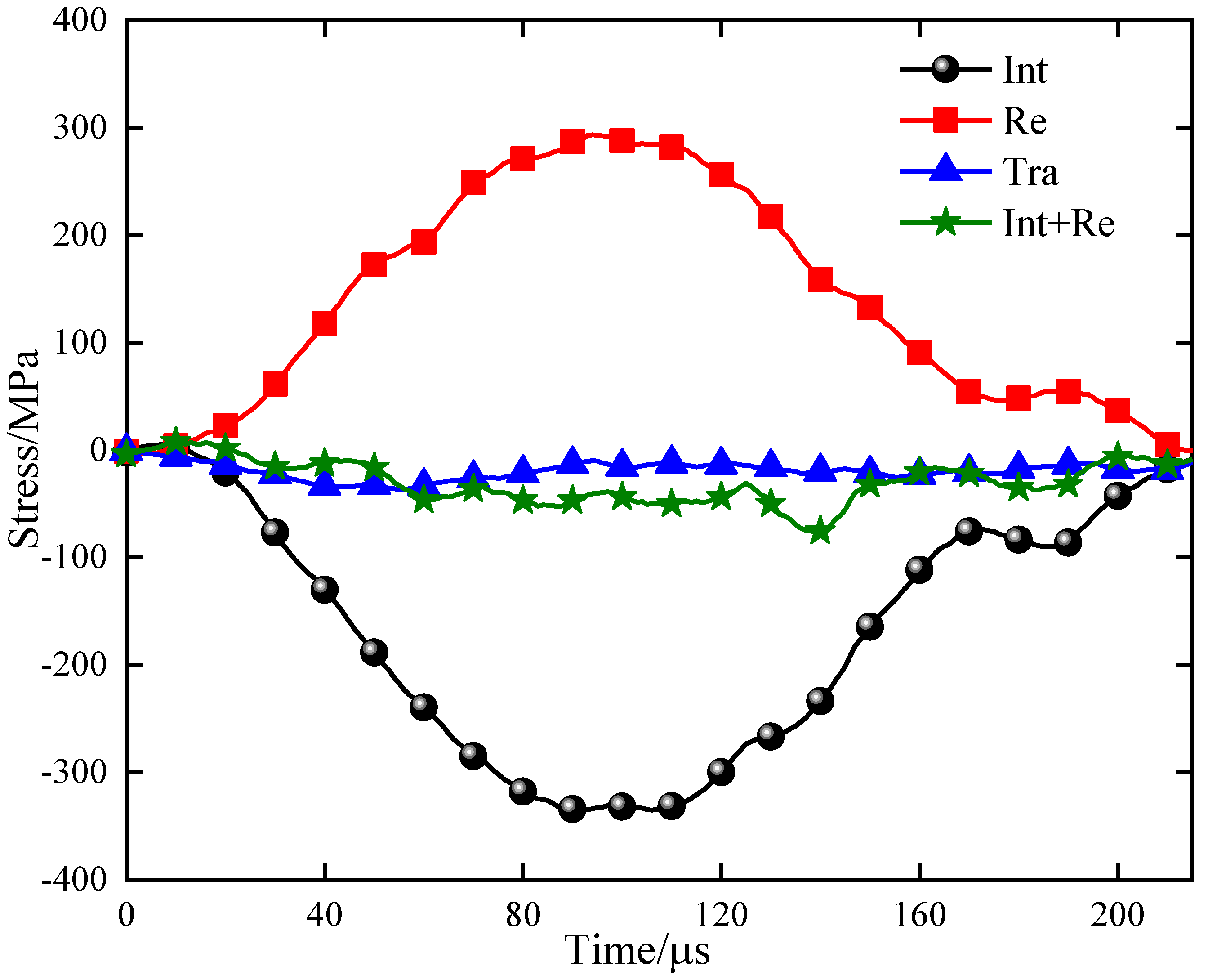
In the dynamic compression test, there were significant changes in the micro strain of the incident bar and transmitted bar, which could be received by the high-speed dynamic strain gauge. In addition, the research showed that the stress balance in the incident bar and the transmitted bar before the failure of the samples was the premise to ensure the reliability of the test results [11]. Therefore, it is necessary to verify the stress balance of the impact samples before analyzing the test results, as shown in Figure 6.
It can be seen from Figure 6 that the superposition curve of incident stress and reflected stress has a high coincidence degree with the transmitted stress curve, indicating that there are stress balance conditions present at both ends of the sample, contributing to the valid test results. It should be noted that the stress balance verification is required for each sample after the impact test; meanwhile, the test data that do not meet the conditions should be discarded and the parallel test should be supplemented.
Based on the stress wave propagation theory and the assumption of one-dimensional dynamic stress wave, the external force on the rock sample could be regarded as the average of the stress on the end face, which can be calculated by the three-wave method [37]. The dynamic strain, dynamic stress, and strain rate of rock samples under impact load can be expressed as
ε ( t ) = C 0 L s 0 t ( ε i n ε r e ε t r ) d t
σ ( t ) = E 0 A 0 ( ε i n + ε r e + ε t r ) 2 A s
ε ˙ ( t ) = C 0 ( ε i n ε r e ε t r ) L s
where C 0 , E 0 , A 0 are the wave velocity, elastic modulus, and cross-sectional area of the elastic bar respectively; ε i n , ε r e , and ε t r are the strain of the incident bar, reflected bar, and transmitted bar respectively when the incident wave, reflected wave, and transmitted wave propagate independently at t time; A s , L s are the length and cross-sectional area of the test sample respectively. When the stress at both ends of the rock sample meets the stress balance assumption (Figure 6), Equations (1)–(3) can be simplified as
ε ( t ) = 2 C 0 L s 0 t ε t r d t
σ ( t ) = E 0 A 0 A s ε t r
ε ˙ ( t ) = 2 C 0 L s ε t r

4.2. Dynamic Mechanical Parameters

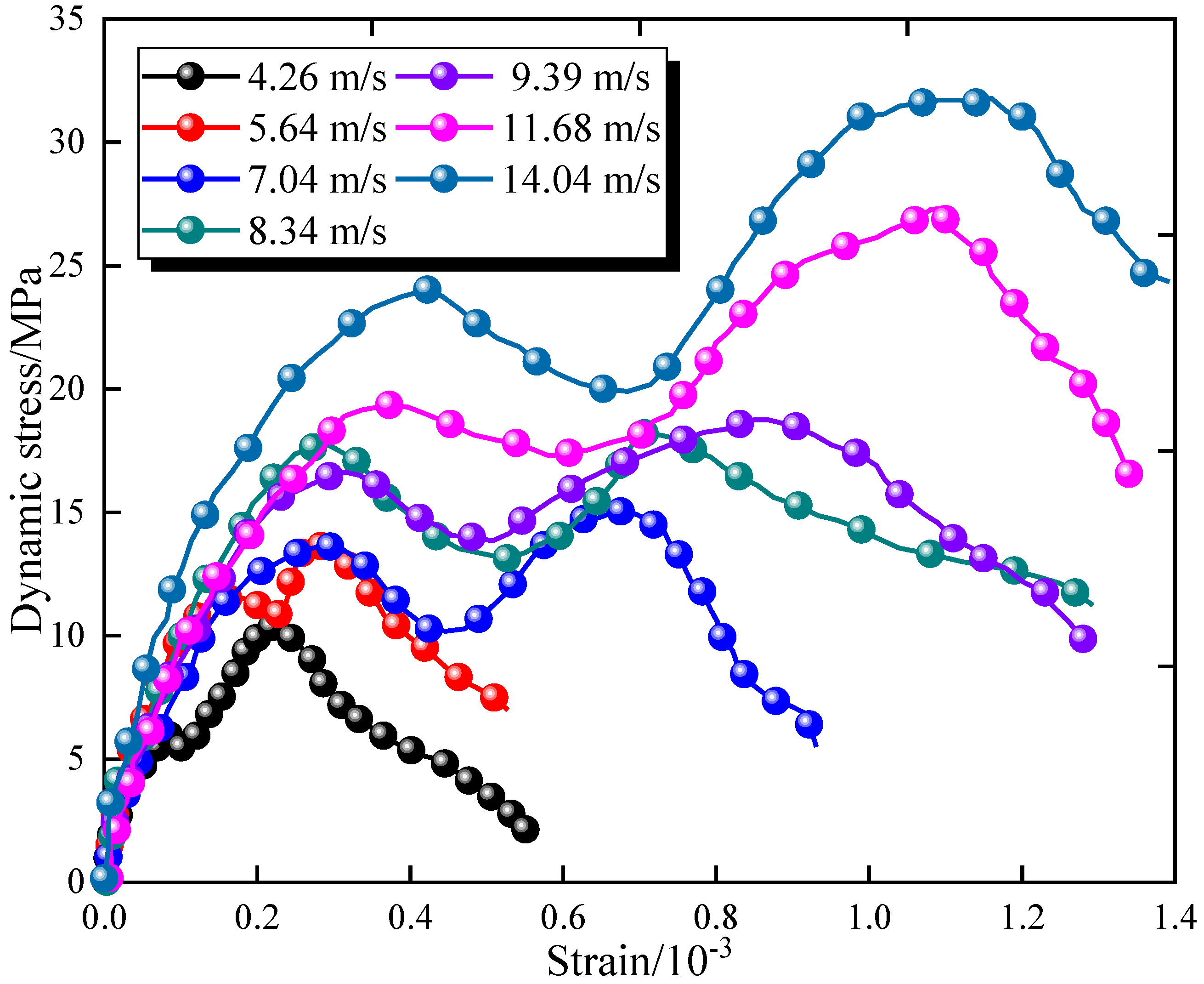
From Equations (4)–(6), the dynamic stress–strain curves of rock samples under different impact velocities could be obtained, and the typical rock samples grouped by different impact velocities were selected for analysis, as shown in Figure 7.
It can be seen from Figure 7 that the peak stress and peak strain of rock samples gradually increase with the impact velocity, and the slope (loading rate) of the linear elastic stage is also continuously increasing, indicating that the increase of impact velocity can effectively improve the strength and the deformation resistance of lignite samples, which is similar to the research results and conclusions from many scholars [11,12,13,14]. Static and quasi-static uniaxial compression tests generally have only one obvious stress peak [23]; however, for impact lignite samples, there are two obvious stress peaks, and with the increase of impact velocity, the bimodal stress characteristics become more obvious. The reason is that the lignite rock sample contains obvious horizontal beddings which have low strength (Figure 5), contributing to the local failure under the action of high-velocity impact, which results in the short-term reduction of the stress; however, after further loading, the integrity of rock sample is improved, and the peak stress continues to rise until the complete failure.
In the early stage of the stress–strain curve for the rock in the static or quasi-static compression test, there is an obvious compaction stage [23,28]. However, the stress of the impact rock sample in this paper shows obvious linear growth characteristics in the early stage of loading, which can be explained as under the low loading rate, the internal defect space of the rock sample can be closed slowly, and the rock sample tends to be complete and then reaches the elastic stage; oppositely, the high strain rate caused by impact makes the defect space of rock sample not fully compressed, which leads to large-scale cracks, and the rock sample reaches the yield stage. It can be seen from Figure 4 and Figure 5 that the rock sample contains mainly micropores and transition pores, and there are few large-scale pores and cracks, so the strain required for the compaction stage is low. In addition, because the sinusoidal stress wave is applied to the end face of the rock sample, the external force on the rock sample gradually decreases after the failure of high-stress loading, which contributes to the obvious post-peak curve. The dynamic mechanical parameters of rock samples were obtained by further calculating and analyzing the experimental data, as shown in Table 1.
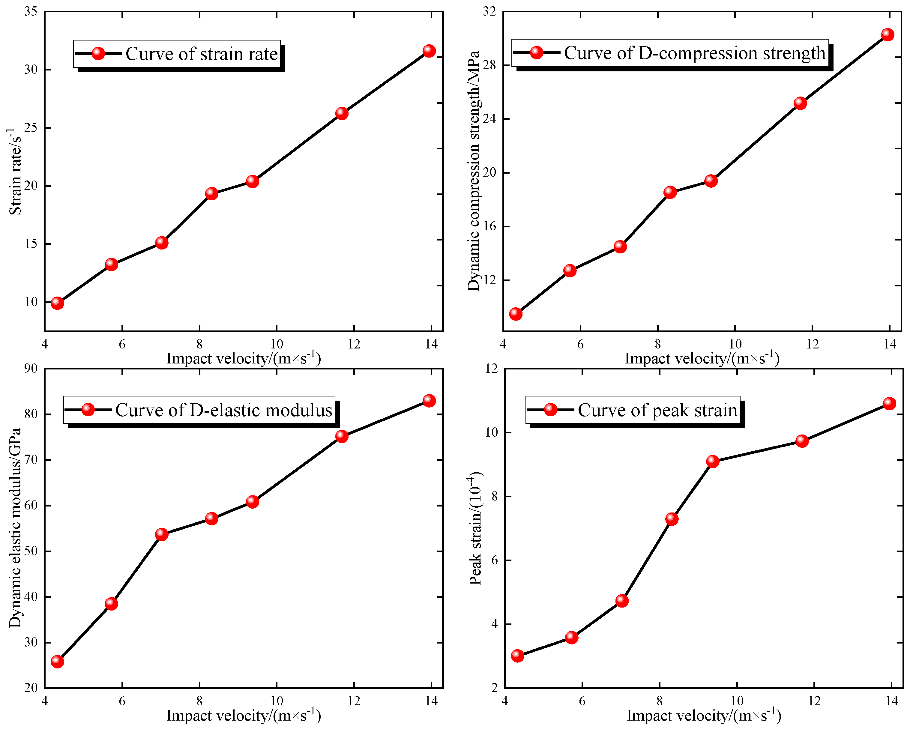
It can be seen from Table 1 that the average impact velocity of the rock sample is increasing in turn from the minimum of 4.33 m/s to the maximum of 13.95 m/s. In addition, the strain rate, peak strength, and dynamic elastic modulus of impact rock samples increase with the impact velocity, in which the strain rate increases from 9.0 s−1 to 31.60 s−1, the peak strength increases from 9.47 MPa to 30.27 MPa, the dynamic elastic modulus increases from 25.78 GPa to 82.94 GPa, and the peak strain increases from 3.01 × 10⁻⁴ to 10.90 × 10⁻⁴, which mean that the increase of impact velocity strengthens the overall mechanical properties of the rock. The evolution law of dynamic mechanical parameters with the increase of impact velocity was further obtained, as shown in Figure 8.
It can be seen from Figure 8 that the strain rate and the peak strength of rock samples show a linear growth trend with the increase of impact velocity; meanwhile, the dynamic elastic modulus shows a “two-stage” linear growth trend, which means the growth rate slows down when the impact velocity exceeds 7.03 m/s; in addition, the peak strain shows obvious three-stage change characteristics, indicating that before the impact velocity increases to 9.38 m/s, the peak strain growth rate of rock samples gradually accelerates, and after the impact velocity continues to increase, the peak strain growth rate decreases and has obvious linear characteristics.
The existing studies have shown that the mechanical properties of impact rock samples have an obvious rate effect, i.e., strain rate hardening effect [7,18,20]. There are three widely accepted explanations: (1) The impact rock sample is in a non-one-dimensional stress state, but the inertial effect caused by the impact load limits the development of a lateral strain of the rock, which is reflected in the improvement of the rock strength [38]. (2) According to the impulse theorem, the energy required for the instantaneous destruction of rock samples should be consistent with that required for quasi-static loading of rock samples; therefore, the energy conservation of rock samples could be achieved only by improving their bearing capacity [39]. (3) Under the action of quasi-static load, there are relative motion characteristics such as friction, overturning, and sliding between rock particles, while trans-granular fracture often occurs between particles under the high-speed impact, which is specifically manifested in the significant improvement of cohesion and internal friction angle of rock samples [40]. It can be seen from Figure 4 and Figure 5 that the rock sample is mainly composed of micropores and transition pores, with relatively few large-scale pores and cracks, which contributes to the high integrity of the rock and the ability to resist the impact of high strain rate. In addition, the interlayer water content of the rock sample is prominent, and the pore water pressure generated under the condition of instantaneous compression can also offset part of the external load and further improve the strength of the rock sample.

4.3. Progressive Failure and Fractal Characteristics

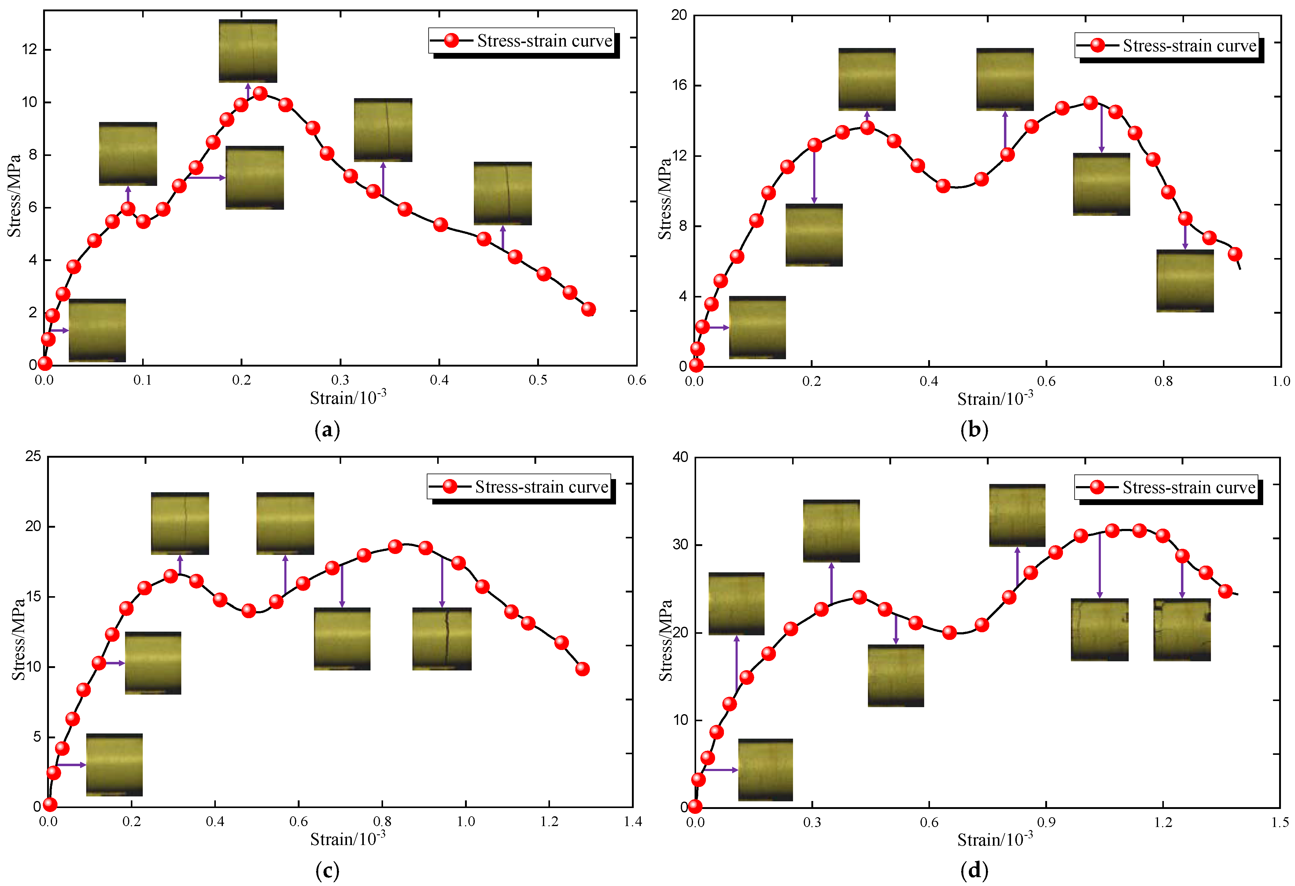
The high-speed cameras were used to capture the dynamic fracture process of lignite samples. At the same time, four groups of rock samples with large impact velocity span were selected for the analysis, which includes group A, group C, group E, and group G, and the impact velocities are 4.26 m/s, 7.04 m/s, 9.39 m/s, and 14.04 m/s respectively, as shown in Figure 9.
It can be seen from Figure 9 that before the impact velocity reaches 9.39 m/s, all the rock samples present radial tensile failure, and the crack coalescence position is basically in the middle of the rock. In the linear-elastic stage, there is no significant change on the surface of the rock until reaching the first stress wave peak, after which there is an obvious macro crack that is consistent with the radial direction in the middle of the rock sample. In addition, before the stress reaches the second peak, the macro crack is compacted, contributing to the complete rock sample and the improvement of bearing capacity; however, after the stress decreases in the post-peak stage, the rock sample breaks and loses stability along the initial macro crack. When the incident bar strikes the rock sample of the G group at the velocity of 14.04 m/s until the stress reaches the first peak, a small macrocrack is generated in the axial direction close to the end face of the transmitted bar, and with a small radial macrocrack generated in the middle of the rock. Similarly, the radial crack of the rock sample is compacted under the continuous application of compressive stress, and in the failure stage, the end axial crack and the radial crack penetrate, contributing to the crushed blocks of the rock.
In order to further study the crushing characteristics of lignite under different impact velocities, each group of rock samples was screened by the standard sieve with the particle size range of 2.5~40 mm, and the mass of the lignite blocks on the standard sieve was weighed, as shown in Figure 10a. The research results showed that the size of rock fragments formed after the impact test had good fractal characteristics [20,30,31]. Mandelbrot and other scholars have established a mass-fractal model to reflect the degree of rock fragmentation, in which the fractal dimension D could be calculated from the mass-frequency relationship. Therefore, the fragment distribution equation of the impact rock sample is
M ( r ) M s = ( r r s ) 3 D
where M ( r ) is the mass of rock fragments with the particle size lower than r , M s is the total mass of rock fragments, r is the diameter of the standard sieve, r s is the maximum particle size of rock fragments, D is the fractal dimension of rock fragments. Taking logarithms at both ends of Equation (7), we can obtain
lg [ M ( r ) M s ] = ( 3 D ) lg ( r r s )
In the double logarithmic coordinate system established by lg [ M ( r ) M s ] lg ( r r s ) , the scattered points were fitted linearly without intercept by the least square method, and the slope of the straight line was 3 D , so the fractal dimension D that quantifies the fragmentation degree of rock samples could be further obtained. Figure 10b shows the evolution law of fracture fractal dimension of rock samples under different impact velocities.
It can be seen from Figure 10a that under the impact velocity of 4.33~8.32 m/s, the rock samples are mostly fractured along the horizontal bedding, with only a small number of fragments; however, with the increase of impact velocity, the number of fractured blocks of a single rock sample gradually increases. After the impact velocity continues to increase, the fracture rock sample is still composed of the large blocks, but also contains obvious small-scale fragments; then, when the impact velocity increases to 14.04 m/s, there is no obvious large block in the impact rock sample, and the small-scale blocks and debris account for the majority. It can be seen from Figure 10b that with the increase of impact velocity, the fragment fractal dimension D of the rock sample increases linearly from 0.24 to 0.79, indicating that the energy generated under high-velocity impact cannot be completely absorbed by the rock sample, which results in the destruction of the rock; meanwhile, with the increase of impact velocity, the energy supply for the rapid development of macrocracks in the rock increases, which is accompanied by the increase of fragmentation degree of the rock sample gradually.

4.4. Evolution Law of Strain Energy

Similar to the quasi-static rock compression, there was also a process of energy accumulation and dissipation in the loading process of impact rock samples [7,10,11,21]. The incident bar strikes the rock samples to provide input energy, and the rock samples store certain elastic energy after the elastic deformation; while in the loading process of the rock, the plastic deformation, and the initiation and expansion of microcracks are closely related to the energy dissipation.
Ma et al. [41] defined the relationship among the input energy, elastic energy, and dissipated energy as
U = U e + U d
where U is the input strain energy, U e is the elastic strain energy, U d is the dissipated strain energy. In addition, the U and U e can be obtained by the following equations.
U = 0 ε 1 σ 1 d ε 1 + 0 ε 2 σ 2 d ε 2 + 0 ε 3 σ 3 d ε 3
U e = 1 2 E ¯ [ σ 1 2 + σ 2 2 + σ 3 2 2 ν ( σ 1 σ 2 + σ 2 σ 3 + σ 1 σ 3 ) ]
where σ 1 , σ 2 , σ 3 are the external stress applied on the material in three directions, ε 1 , ε 2 , ε 3 are the strain of the material due to stress application, E and ν are the elastic modulus and Poisson’s ratio of the material respectively.
Because there is no confine in the uniaxial compression test, i.e., σ 2 = σ 3 = 0, therefore, the simplified form of Equations (10) and (11) can be obtained as
U = 0 ε 1 σ 1 d ε 1
U e = σ 1 2 2 E ¯
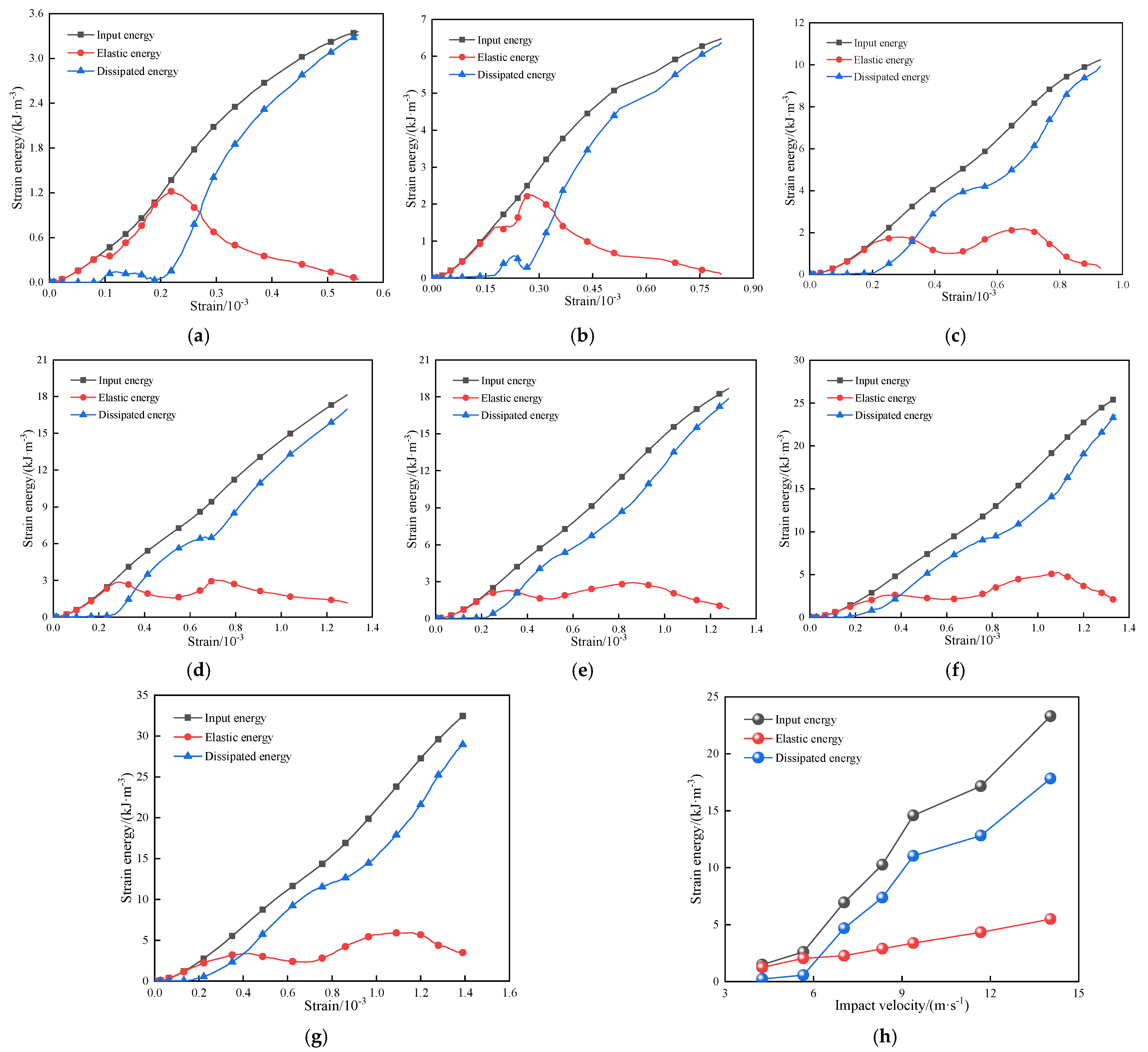
The stress–strain curves of rock samples with different impact velocities were analyzed, and the progressive evolution law of input energy, elastic energy, and dissipated energy of rock samples were calculated, as shown in Figure 11. In addition, the strain energy before the peak of each group rock samples was further calculated, as shown in Table 2.
It can be seen from Figure 11a–g that when the impact velocity is lower than 7.03 m/s, the input energy growth shows a changing trend of “steep first and then slow” with the increase of impact velocity, while after continuing to increase the impact velocity, the input energy increases linearly. The elastic energy curve of the rock sample is similar to the stress–strain curve, and there are two obvious peaks in the loading process; meanwhile, when the impact velocity is lower than 7.03 m/s, the second peak is more obvious, and the difference between the two peaks gradually decreases with the increase of the impact velocity. In addition, it is found that in the early stage of the loading process, there is a high coincidence degree between the elastic energy and the input energy, which means that the input energy of rock samples is mostly transformed into elastic energy at this time. The start strain point of the dissipated energy lags behind the input energy obviously, but the growth trend of dissipated energy is similar to the change of the input energy. Meanwhile, because the elastic property increases slowly in the later stage, the dissipated energy becomes the main conversion form of the input energy, and the maximum of the dissipated energy is closed to the peak of the input energy.
It can be seen from Figure 11h and Table 2 that after the impact velocity increases from 4.03 m/s to 14.04 m/s, the pre-peak input energy of the rock sample increases from 1.48 kJ/m3 to 23.30 kJ/m3, the pre-peak elastic energy increases from 1.25 kJ/m3 to 5.49 kJ/m3, and the pre-peak dissipated energy increases from 0.23 kJ/m3 to 17.82 kJ/m3. Consequently, the input energy and dissipated energy of the rock increase obviously with the impact velocity, which increases slowly at low velocity and rapidly at high velocity. The pre-peak elastic energy shows a slow linear growth trend with the impact velocity, and there is an increasing difference among the pre-peak elastic energy, the input energy, and the dissipated energy.
The carried kinetic energy of the incident bar increases with the impact velocity, therefore, the input energy, elastic energy, and dissipated energy of the rock will inevitably increase accordingly. The energy not used for elastic deformation of rock samples will be dissipated in other forms, including sound energy, heat energy, light energy, etc., [23,40]. For impact rock samples, there is also energy release on the incident bar during the loading process, i.e., reflected energy, and with the increase of impact velocity, the dissipated energy increases significantly, which indirectly proves that the reflected energy is also gradually increasing, which is similar to the research conclusions of many scholars [11,21]. From the stress–strain curve, it can be seen that the elastic stage of the rock sample accounts for a relatively low proportion in the whole loading process, so the growth of elastic energy is not obvious. In Figure 9, the macrocrack of the rock occurs in the elastic stage, which contributes to the weakening of the elastic energy storage ability of the rock sample.

5. Interlayer Fracture Mechanism of Lignite under Dynamic Compression

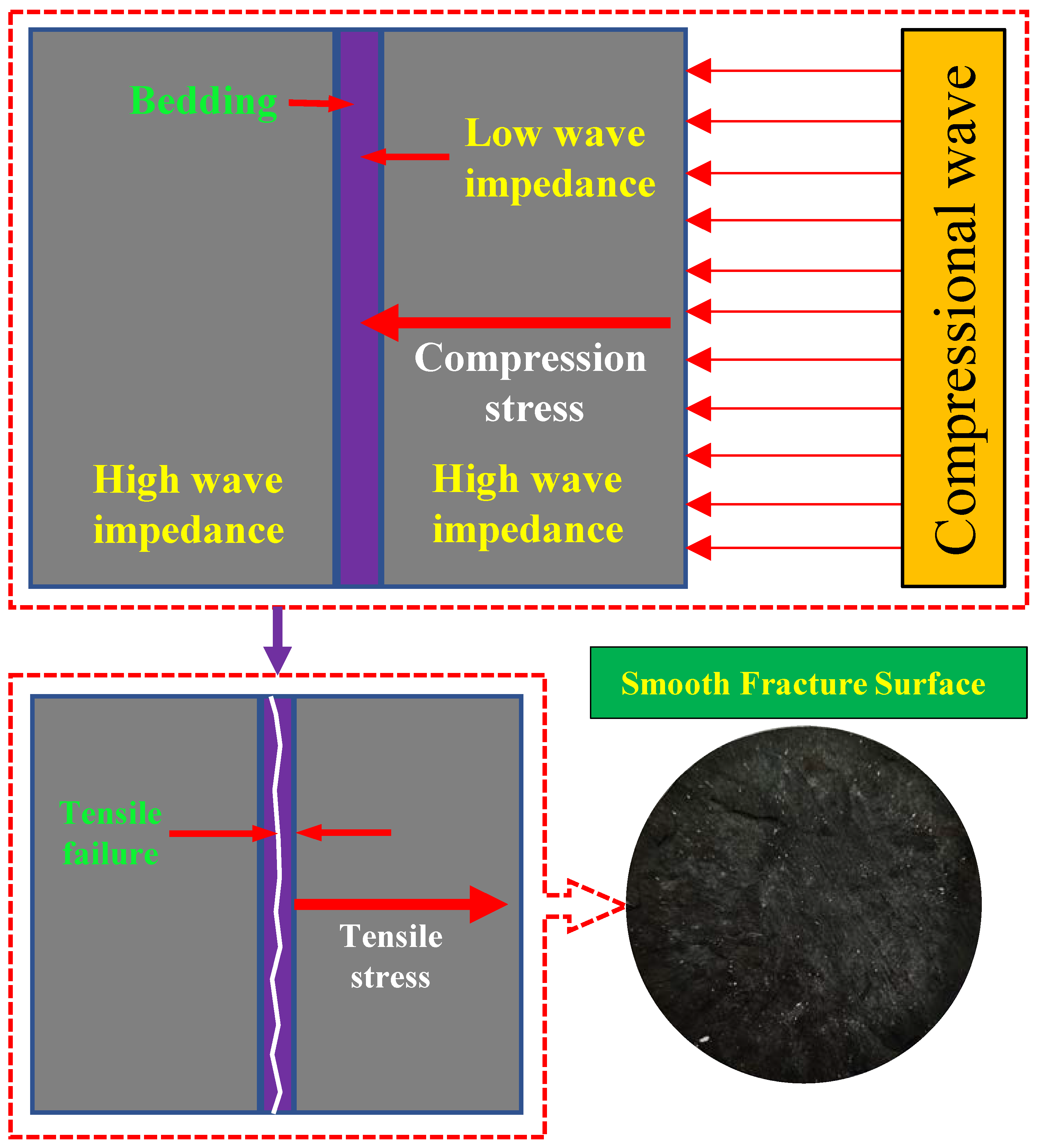
It can be seen from Figure 9 that when the impact velocity is lower than 14.03 m/s, the rock sample mainly shows the interlayer fracture, and the fracture surface is smooth and flat, basically along the radial direction. Therefore, it is necessary to discuss the interlayer fracture failure mechanism of the rock sample, as shown in Figure 12.
As shown in Figure 4, there are obvious horizontal bedding characteristics in the rock sample, and the vertical bedding plane direction has good homogeneity. At the same time, the obvious interlayer fracture has occurred in the process of thin slices, and there is a significant difference between the fractured material and the retained matrix, which finally demonstrates that there is a significant low-strength bedding structure in the lignite. At the same time, as shown in Figure 5, the internal pore and fissure space of the rock sample are small, and the local water content is prominent, distributed in banded areas, extending in the bedding direction, which results in softening characteristics of the rock matrix by the water-rock weakening [23]. To sum up, there must be a weak layer structure in the lignite sample, which may have an important influence on the failure characteristics of the impact rock.
There is reflection and transmission phenomena when the stress wave propagates to the interface of two materials, which is caused by the different wave impedance of two materials [42]. Wave impedance refers to the stress required by the solid materials to produce vibration, which means the greater the wave impedance, the greater the external stress required. The wave impedance can be expressed as
I w = ρ c w
where I w and c w are the wave impedance and wave velocity of the solid materials respectively. Chai et al. [43] defined the reflection coefficient between two media under impact as
R = I w 1 I w 2 I w 1 + I w 2
where I w 1 and I w 2 are the wave impedance of initial medium and propagation medium respectively. It can be seen from Equation (15) that the greater the difference in wave impedance between the two mediums, the higher the reflection coefficient, causing the greater reflected stress.
It can be seen from Figure 12 that there is an obvious weak layer structure in the lignite sample, and its wave impedance is lower than that of the adjacent high-strength medium. Therefore, when the stress wave propagates to the interlayer interface, a significant stress wave reflection will occur, which then results in the generation of the tensile stress wave perpendicular to the bedding direction; meanwhile, the tensile strength of the rock in the vertical bedding direction is far lower than its compressive strength, which results in the interlaminar fracture failure of the rock under the action of tensile stress. In addition, it is found that the rock sample does not always bear compression in the impact test, which is specifically manifested in the loading and unloading process; therefore, the instantaneous pressure relief will also produce obvious tensile stress in the rock, aggravating the tensile failure of the rock. When the impact velocity increases, the stress reflection between the internal bedding of the rock sample is frequent, resulting in the existence of multiple bedding failure surfaces, which is consistent with the above analysis results. However, when the impact velocity reaches 14.04 m/s, the energy provided by impact compression is enough to completely break the rock sample, and the rock sample is compressed into broken blocks.

6. Conclusions

In this paper, the mechanical behavior and failure mechanism of lignite under impact were studied to provide a reference for the slope stability analysis under blasting impact in an open-pit mine. The specific conclusions are as follows.
(1)
The content of other impurities such as clay accounts for more than 24.40% of lignite; meanwhile, the axial direction of the cylindrical rock sample has obvious bedding characteristics, and the interlayer material has low strength; then, the interior of the rock sample is dominated by micropores and transition pores, with obvious internal water content characteristics, and there is a high-water content banded area in the rock, which is parallel to the bedding direction.
(2)
The stress–strain curve of impact lignite has obvious “double peak” characteristics; furthermore, the strain rate and dynamic compression strength increase linearly with the impact velocity, while the growth of dynamic elastic modulus and peak strain slows down in the later stage. In the process of impact loading, a macro crack appears at the first stress wave peak, and then is compressed until the interlayer fracture of the rock sample occurs; meanwhile, the fractal dimension of rock fragmentation increases linearly with the impact velocity, which reveals that the fragmentation degree of rock sample increases gradually.
(3)
The input energy and dissipated energy of impact lignite increase rapidly in stages with the impact velocity, and the elastic energy increases slowly at a low level. The interlaminar fracture mechanism of lignite samples can be explained as when the stress wave propagates from the high wave impedance rock medium to the low wave impedance medium, the stress wave reflection phenomenon will occur at the interface, and then a significant tensile stress wave will be generated, which contributes to the tensile failure of the rock along the beddings; in addition, the vibration effect of the incident bar during impact process will also aggravate the rock tensile failure.
(4)
Although we have obtained the mineral composition of the test lignite by using the advanced test techniques, in terms of the analysis of the mechanical behaviors and the failure mechanism of rock samples, we emphatically consider the influence of the microstructure, which can completely account for the test phenomenon. Although the influence of the mineral composition is not the key point of this paper, we will continue to carry out relevant research to fully explore its influence mechanism.

Author Contributions

Conceptualization, H.M.; methodology, H.M. and Y.S.; data curation, H.M. and Y.S.; formal analysis, J.Y. (Jiangkun Yang), J.Z., and J.Y. (Juntao Yang); writing—original draft, H.M., Y.S., and W.B. All authors have read and agreed to the published version of the manuscript.

Funding

This research was funded by the State Key Laboratory of Coal Resources and Safe Mining, China University of Mining and Technology, Beijing (SKLCRSM20KFA11), the Fundamental Research Funds for the Central Universities (2022YJSLJ09).

Institutional Review Board Statement

Not applicable.

Informed Consent Statement

Not applicable.

Data Availability Statement

The data used to support the findings of this study are available from the corresponding author upon request.

Conflicts of Interest

The authors declare no known competing personal relationships or financial interests that could have appeared to influence the work reported in this paper.

References

  1. Aler, J.; Mouza, J.D.; Arnould, M. Measurement of the fragmentation efficiency of rock mass blasting and its mining applications. Int. J. Rock Mech. Min. Sci. Geomech. Abstr. 1996, 33, 125–139. [Google Scholar] [CrossRef]
  2. Xie, L.X.; Lu, W.B.; Zhang, Q.B. Damage evolution mechanisms of rock in deep tunnels induced by cut blasting. Tunn. Undergr. Space Technol. 2016, 58, 257–270. [Google Scholar] [CrossRef]
  3. Gong, F.Q.; Luo, Y.; Li, X.B. Experimental simulation investigation on rockburst induced by spalling failure in deep circular tunnels. Tunn. Undergr. Space Techol. 2018, 81, 413–427. [Google Scholar] [CrossRef]
  4. Liu, C.Y.; Yang, J.X.; Yu, B. Rock-breaking mechanism and experimental analysis of confined blasting of borehole surrounding rock. Int. J. Min. Sci. Technol. 2017, 27, 795–801. [Google Scholar] [CrossRef]
  5. Wei, D.; Chen, M.; Ye, Z.W. Study on blasting failure zone based on rate-dependent dynamic characteristics of rock mass. Chin. J. Adv. Eng. Sci. 2021, 53, 67–74. [Google Scholar] [CrossRef]
  6. Ding, X.H.; Lu, X.; Zhou, W. Blasting impact simulation test and fragmentation distribution characteristics in an open-pit mine. Shock Vib. 2019, 2019, 4080274. [Google Scholar] [CrossRef]
  7. Shi, L.; Xu, J. Effect of strain rate on the dynamic compressive mechanical behaviors of rock material subjected to high temperatures. Mech. Mater. 2015, 82, 28–38. [Google Scholar] [CrossRef]
  8. Zhou, Y.X.; Xia, K.; Li, X.B. Suggested methods for determining the dynamic strength parameters and mode-I fracture toughness of rock materials. Int. J. Rock Mech. Min. Sci. 2012, 49, 105–112. [Google Scholar] [CrossRef]
  9. Kawahara, S.; Muro, T. Effects of dry density and thickness of sandy soil on impact response due to rockfall. J. Terramechanics 2006, 43, 329–340. [Google Scholar] [CrossRef]
  10. He, M.C.; Gong, W.L.; Wang, J. Development of a novel energy-absorbing bolt with extraordinarily large elongation and constant resistance. Int. J. Rock Mech. Min. Sci. 2014, 67, 29–42. [Google Scholar] [CrossRef]
  11. Mishra, S.; Khetwal, A.; Chakraborty, T. Dynamic Characterisation of geniss. Rock Mech. Rock Eng. 2019, 52, 61–81. [Google Scholar] [CrossRef]
  12. Li, X.B.; Lok, T.S.; Zhao, J. Dynamic characteristics of granite subjected to intermediate loading rate. Rock Mech. Rock Eng. 2005, 38, 21–39. [Google Scholar] [CrossRef]
  13. Fakhimi, A.; Azhdari, P.; Kimberley, J. Physical and numerical evaluation of rock strength in Split Hopkinson Pressure Bar testing. Comput. Geotech. 2018, 102, 1–11. [Google Scholar] [CrossRef]
  14. Dai, F.; Huang, S.; Xia, K.W. Some fundamental issues in dynamic compression and tension tests of rocks using split Hopkinson pressure bar. Rock Mech. Rock Eng. 2010, 43, 657–666. [Google Scholar] [CrossRef]
  15. Mishra, S.; Chakraborty, T. Determination of high-strain-rate stress–strain response of granite for blast analysis of tunnels. J. Eng. Mech. 2019, 145, 04019057. [Google Scholar] [CrossRef]
  16. Ning, J.G.; Ren, H.L.; Guo, T.T. Dynamic response of alumina ceramics impacted by long tungsten projectile. Int. J. Impact Eng. 2013, 62, 60–74. [Google Scholar] [CrossRef]
  17. Yao, W.; Xia, K.W. Dynamic notched semi-circle bend (NSCB) method for measuring fracture properties of rocks: Fundamentals and applications. J. Rock Mech. Geotech. Eng. 2019, 11, 1066–1093. [Google Scholar] [CrossRef]
  18. Wang, P.; Xu, J.Y.; Liu, S. Static and dynamic mechanical properties of sedimentary rock after freeze-thaw or thermal shock weathering. Eng. Geol. 2016, 210, 148–157. [Google Scholar] [CrossRef] [Green Version]
  19. Gong, F.Q.; Shi, X.F.; Li, X.B. Dynamic triaxial compression tests on sandstone at high strain rates and low confining pressures with split Hopkinson pressure bar. Int. J. Rock Mech. Min. Sci. 2019, 113, 211–219. [Google Scholar] [CrossRef]
  20. Zhao, H.H.; Liu, C.; Zhang, J. Breakage behavior of gravel rock particles under impact force. Comput. Part. Mech. 2021, 8, 1075–1087. [Google Scholar] [CrossRef]
  21. Gong, F.Q.; Jia, H.Y.; Zhang, Z.X. Energy dissipation and particle size distribution of granite under different incident energies in SHPB compression tests. Shock Vib. 2020, 2020, 8899355. [Google Scholar] [CrossRef]
  22. Zhang, C.H.; He, X.W.; Zhu, S.Q. Distribution, character and utilization of lignite in China. In Proceedings of the Asia-Pacific Power and Energy Engineering Conference, Wuhan, China, 25–28 March 2011. [Google Scholar] [CrossRef]
  23. Ma, H.F.; Song, Y.Q.; Chen, S.J. Experimental investigation on the mechanical behavior and damage evolution mechanism of water immersed gypsum rock. Rock Mech. Rock Eng. 2021, 54, 4929–4948. [Google Scholar] [CrossRef]
  24. Ma, H.F.; Chen, S.J.; Song, Y.Q. Experimental investigation into the effects of composition and microstructure on the tensile properties and failure characteristics of different gypsum rocks. Sci. Rep. 2021, 11, 14517. [Google Scholar] [CrossRef] [PubMed]
  25. Chen, M.; Zang, C.W.; Ding, Z.W. Effects of confining pressure on deformation failure behavior of jointed rock. J. Cent. South Univ. 2022, 29, 1305–1319. [Google Scholar] [CrossRef]
  26. Chen, M.; Yang, S.Q.; Ranjith, P.G. Cracking behavior of rock containing non-persistent joints with various joints inclinations. Theor. Appl. Frac. Mec. 2020, 109, 102701. [Google Scholar] [CrossRef]
  27. Pikryl, R. Some microstructural aspects of strength variation in rocks. Int. J. Rock Mech. Min. Sci. 2001, 38, 671–682. [Google Scholar] [CrossRef]
  28. Song, Y.Q.; Ma, H.F.; Li, X.S. Experimental investigation on the influence of water content on mechanical properties and failure characteristics of tuff. Geotech. Geol. Eng. 2021, 39, 2871–2882. [Google Scholar] [CrossRef]
  29. Yang, J.U.; Wang, H.J.; Yang, Y.M. Numerical simulation of mechanisms of deformation, failure and energy dissipation in porous rock media subjected to wave stresses. Sci. China Technol. Sci. 2010, 53, 1098–1113. [Google Scholar] [CrossRef]
  30. Yu, L.Y.; Zhang, Z.Q.; Wu, J.Y. Experimental study on the dynamic fracture mechanical properties of limestone after chemical corrosion. Theor. Appl. Fract. Mec. 2020, 108, 102620. [Google Scholar] [CrossRef]
  31. Liu, X.H.; Dai, F.; Zhang, R. Static and dynamic uniaxial compression tests on coal rock considering the bedding directivity. Environ. Earth Sci. 2015, 73, 5933–5949. [Google Scholar] [CrossRef]
  32. Zhao, Y.X.; Gong, S.; Hao, X.J. Effects of loading rate and bedding on the dynamic fracture toughness of coal: Laboratory experiments. Eng. Fract. Mec. 2017, 178, 375–391. [Google Scholar] [CrossRef]
  33. Han, J.; Zhang, L.; Kim, H.J. Fast pyrolysis and combustion characteristic of three different brown coals. Fuel Process. Technol. 2018, 176, 15–20. [Google Scholar] [CrossRef]
  34. Xin, F.D.; Xu, H.; Tang, D.Z. Experimental study on the change of reservoir characteristics of different lithotypes of lignite after dehydration and improvement of seepage capacity. Fuel 2020, 277, 118196. [Google Scholar] [CrossRef]
  35. Yao, Y.B.; Liu, D.M.; Xie, S.B. Quantitative characterization of methane adsorption on coal using a low-field NMR relaxation method. Int. J. Coal Geol. 2014, 131, 32–40. [Google Scholar] [CrossRef]
  36. Zhou, H.W.; Liu, Z.L.; Sun, X.T. Evolution characteristics of seepage channel during water infusion in deep coal samples. J. China Coal Soc. 2021, 46, 867–875. [Google Scholar] [CrossRef]
  37. Xia, K.; Nasseris, M.H.B.; Mohanty, B. Effects of microstructures on dynamic compression of Barre granite. Int. J. Rock Mec. Min. Sci. 2008, 45, 879–887. [Google Scholar] [CrossRef]
  38. Janach, W. The role of bulking in brittle failure of rocks under rapid compression. Int. J. Rock Mech. Min. Sci. Geomech. Abstr. 1976, 13, 177–186. [Google Scholar] [CrossRef]
  39. Wang, D.R.; Hu, S.S. Influence of aggregate on the compression properties of concrete under impact. Chin. J. Exp. Mec. 2002, 17, 23–27. [Google Scholar]
  40. Liu, J.Z.; Xu, J.Y.; Lv, X.C. Experimental study on dynamic mechanical properties of amphibolites under impact compressive loading. Chin. J. Rock Mech. Eng. 2009, 28, 2113–2120. [Google Scholar] [CrossRef]
  41. Ma, Q.; Tan, Y.L.; Liu, X.S. Effect of coal thicknesses on energy evolution characteristics of roof rock-coal-floor rock sandwich composite structure and its damage constitutive model. Compos. Part B-Eng. 2020, 198, 108086. [Google Scholar] [CrossRef]
  42. Yang, R.S.; Li, W.Y.; Fang, S.Z. Experimental study on impact dynamic characteristics of layered composite rocks. Chin. J. Rock Mech. Eng. 2019, 38, 1747–1757. [Google Scholar] [CrossRef]
  43. Chai, S.B.; Wang, H.; Jing, Y.L. Experimental study on dynamic compression characteristics of rock with filled joints after cumulative damage. Chin. J. Rock Mech. Eng. 2020, 39, 2025–2037. [Google Scholar] [CrossRef]
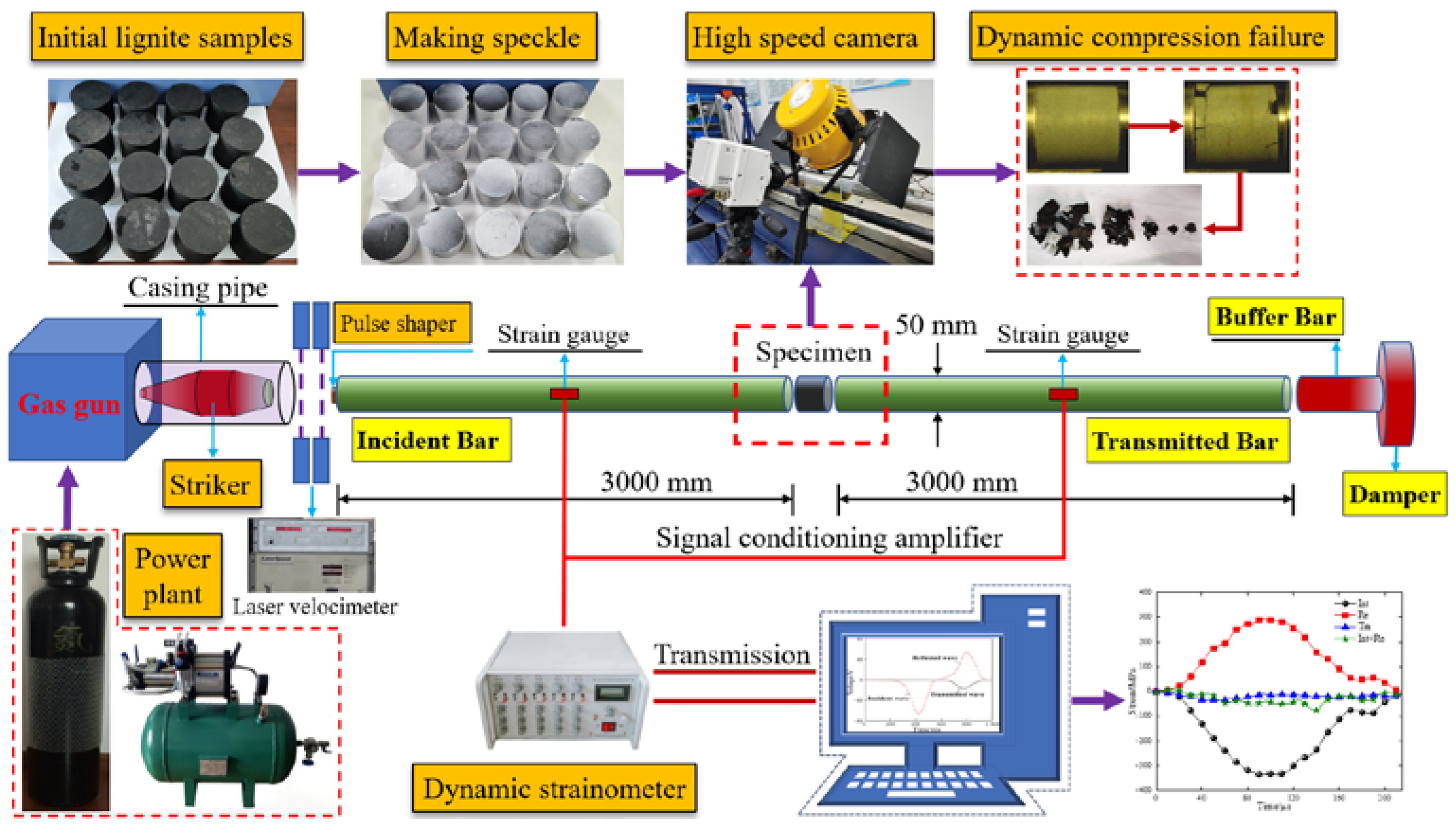
Figure 1. Dynamic compression test system of lignite based on SHPB.
Sustainability 14 10528 g001
Figure 2. Composition and microstructure test scheme of lignite.
Sustainability 14 10528 g002
Figure 3. Composition of test lignite.
Sustainability 14 10528 g003
Figure 4. Thin slice analysis on microstructural characteristics of lignite.
Sustainability 14 10528 g004
Figure 5. NMR T2 spectrum and imaging of lignite: (a) is the NMR T2 spectrum; (b) is the NMR imaging picture.
Sustainability 14 10528 g005
Figure 6. Dynamic stress balance at both ends of lignite sample.
Sustainability 14 10528 g006
Figure 7. Dynamic compressive stress–strain curve of lignite under different impact velocities.
Sustainability 14 10528 g007
Figure 8. Evolution characteristics of dynamic mechanical parameters of lignite with different impact velocities.
Sustainability 14 10528 g008
Figure 9. Progressive failure characteristics of lignite with different impact velocities: (ad) represent the lignite sample in group A, C, E, and G respectively.
Sustainability 14 10528 g009
Figure 10. Fragmentation and fractal characteristics of lignite: (a,b) are the fragment characteristics and the fragment fractal dimension of lignite under different impact velocities respectively.
Sustainability 14 10528 g010
Figure 11. Evolution law of strain energy of lignite under different impact velocities: (ag) represent the strain energy evolution in the impacting process for A~G group samples, (h) is the change law of the strain energy with the increase of impact velocity.
Sustainability 14 10528 g011
Figure 12. Interlayer fracture mechanism of impact lignite.
Sustainability 14 10528 g012
Table 1. Experimental results of lignite from the impact compression test.
GroupImpact Velocity
/(m/s)
Strain Rate
/s−1
Peak Strength
/MPa
Dynamic Elastic Modulus
/GPa
Peak Strain
/10−4
A4.26~4.739.21~10.808.28~10.3024.14~28.423.01
4.339.909.4725.78
B5.65~6.1712.08~14.3211.60~13.7235.98~41.483.58
5.7313.2312.7038.47
C6.96~7.1012.80~16.6212.32~15.9251.86~55.204.73
7.0315.1014.4753.67
D8.28~8.3518.79~19.7418.04~18.9554.81~58.807.29
8.3219.3318.5357.11
E9.30~9.4519.63~22.7419.32~21.7460.24~61.099.09
9.3820.7319.8360.80
F11.50~11.8924.80~29.4123.32~27.2470.99~79.959.73
11.6926.2325.1775.13
G13.88~14.0430.94~33.2829.61~31.9475.69~88.0510.90
13.9531.6030.2782.94
Table 2. Evolution law of strain energy of lignite under different impact velocities.
GroupImpact Velocity
/(m × s−1)
Input Energy
/(kJ/m3)
Elastic Energy
/(kJ/m3)
Dissipated Energy
/(kJ/m3)
A4.331.481.250.23
B5.732.602.040.56
C7.036.952.274.69
D8.3210.262.897.37
E9.3814.583.3811.03
F11.6917.164.3312.82
G13.9523.305.4917.82
Publisher’s Note: MDPI stays neutral with regard to jurisdictional claims in published maps and institutional affiliations.