A New Nonlinear Controller for the Maximum Power Point Tracking of Photovoltaic Systems in Micro Grid Applications Based on Modified Anti-Disturbance Compensation
Abstract
:1. Introduction
- i.
- A new nonlinear controller is proposed as a new nonlinear state error feedback (NLSEF). The new nonlinear controller consists of a proposed tracking differentiator (TD) combined with a new super twisting sliding mode controller (STC-SM).
- ii.
- A new nonlinear extended state observer (NLESO) is proposed to estimate the total disturbance of the PV system.
- iii.
- Last but not least, the modified ADRC is composed of the aforementioned proposed nonlinear controller (i.e., STC-SM) and the proposed NLESO to stabilize the system and track the MPP in the presence of disturbance and parameter variations.
2. PV System Characteristics and Modeling
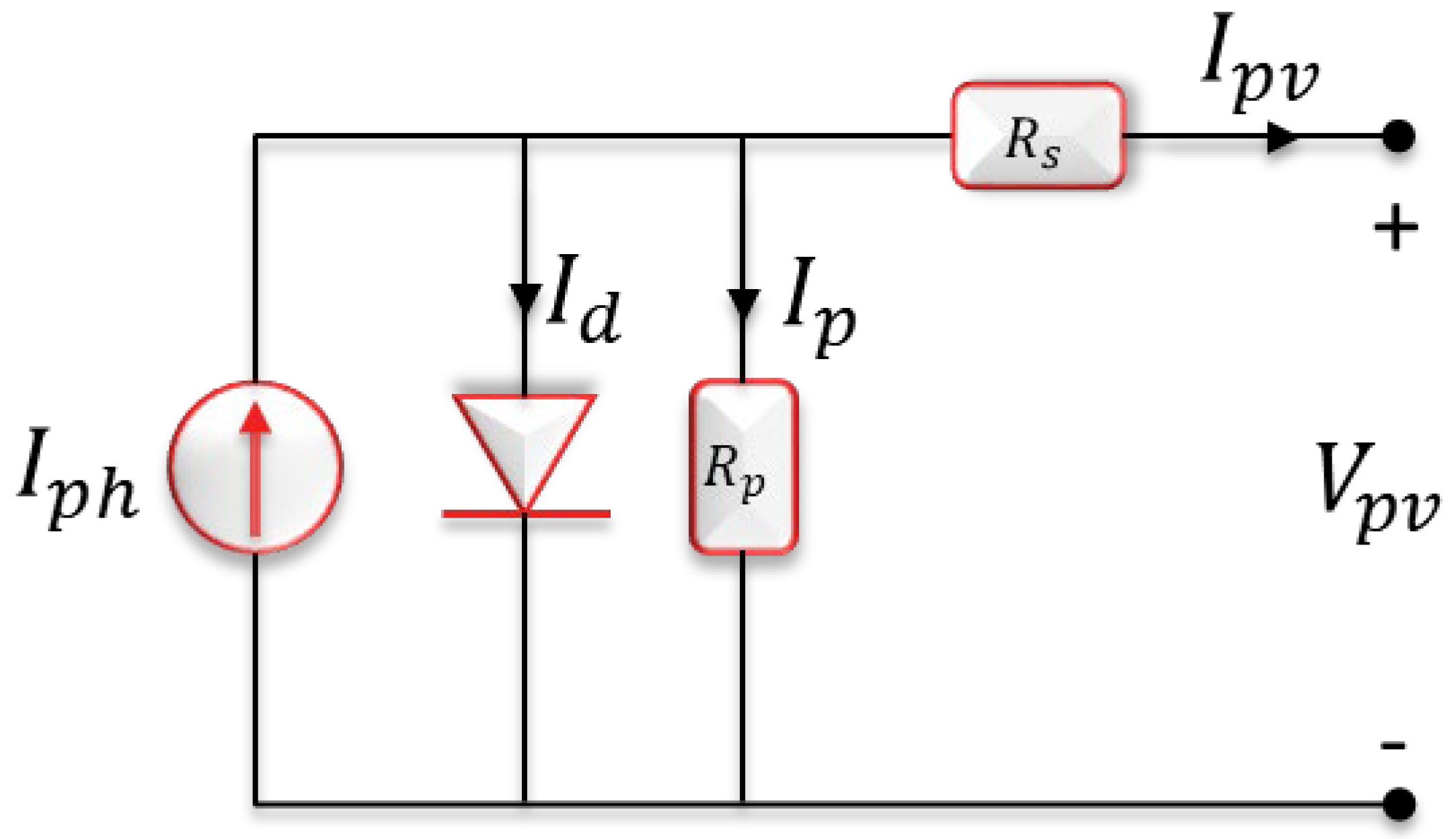
2.1. PV System Modeling
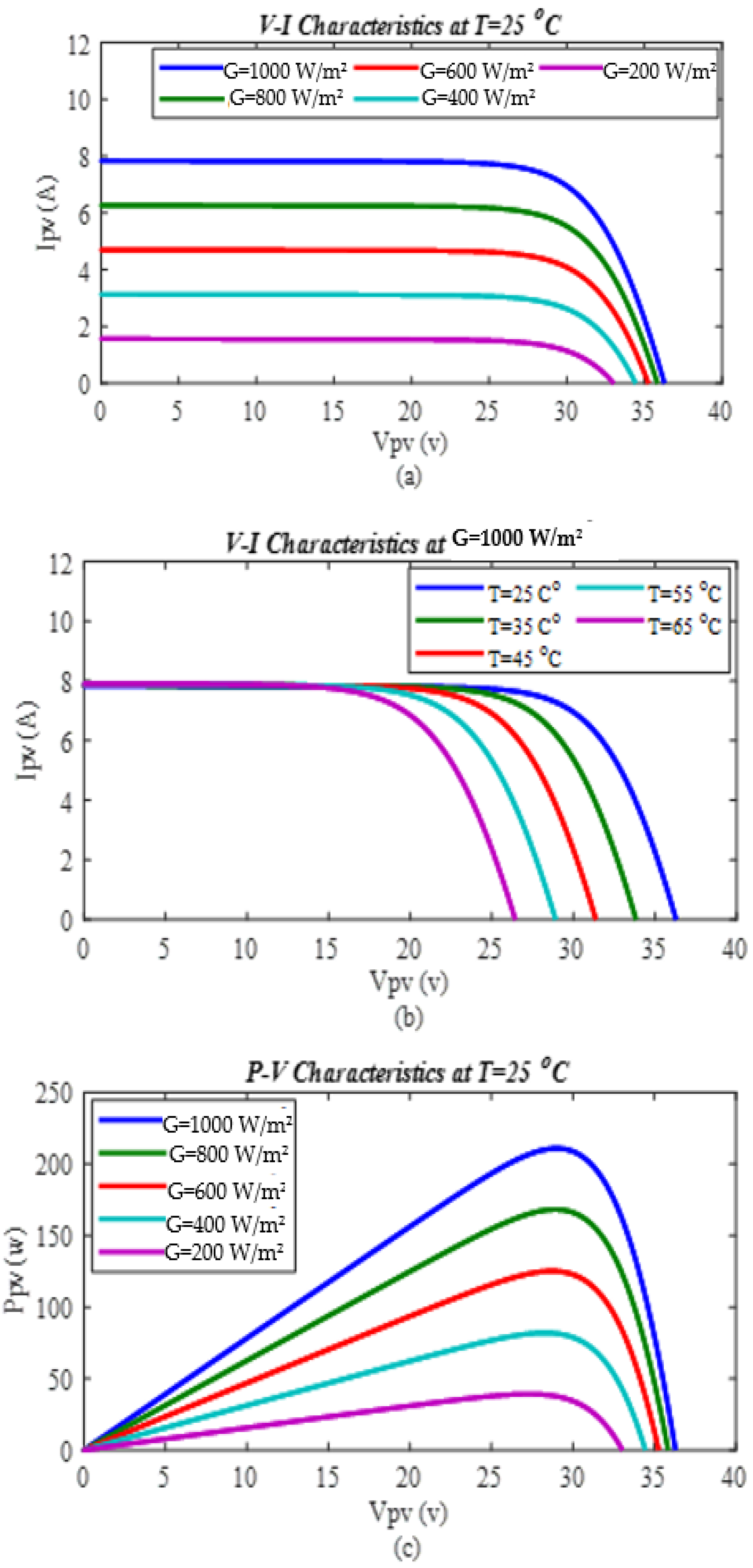
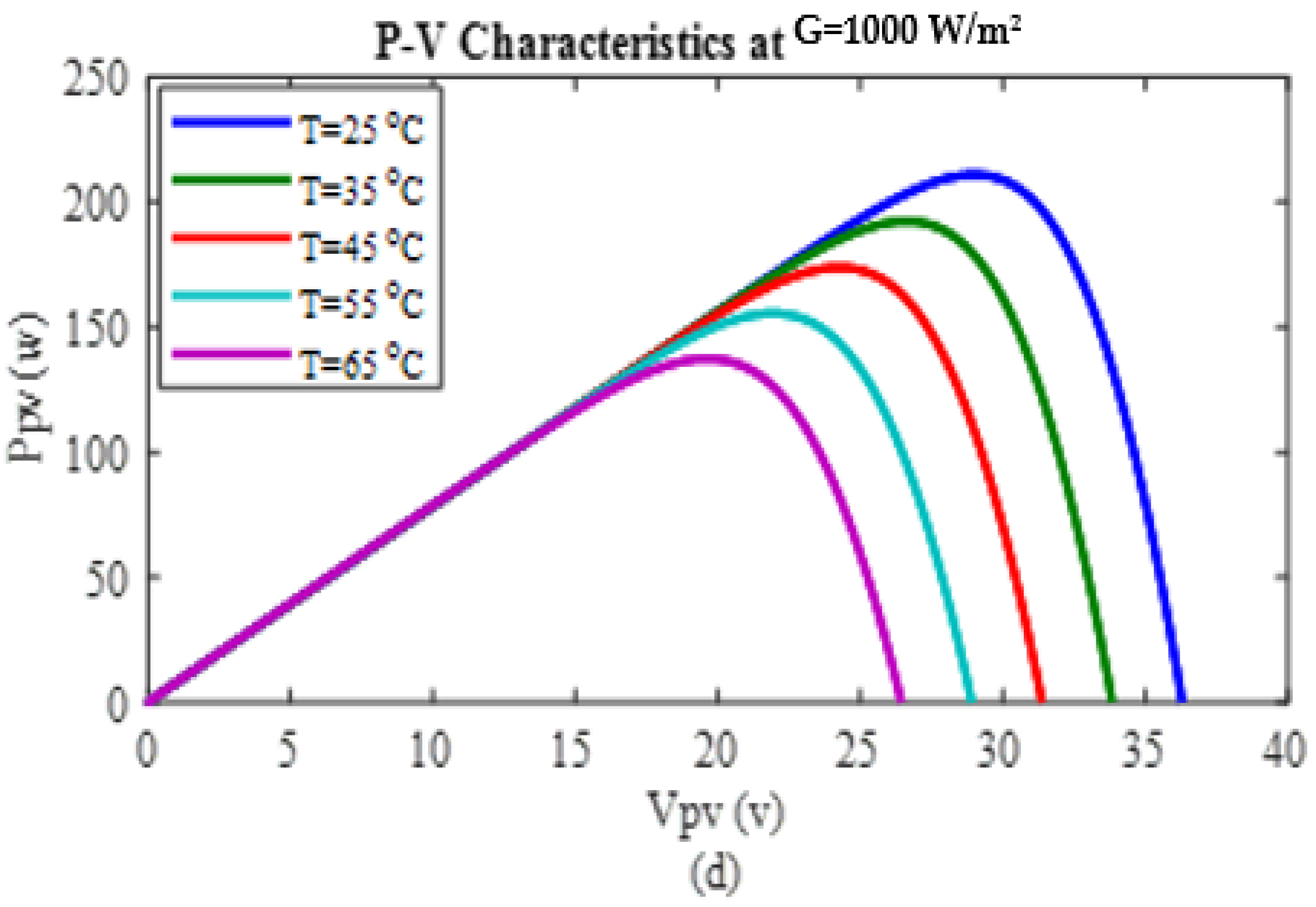
2.2. PV System Characteristics
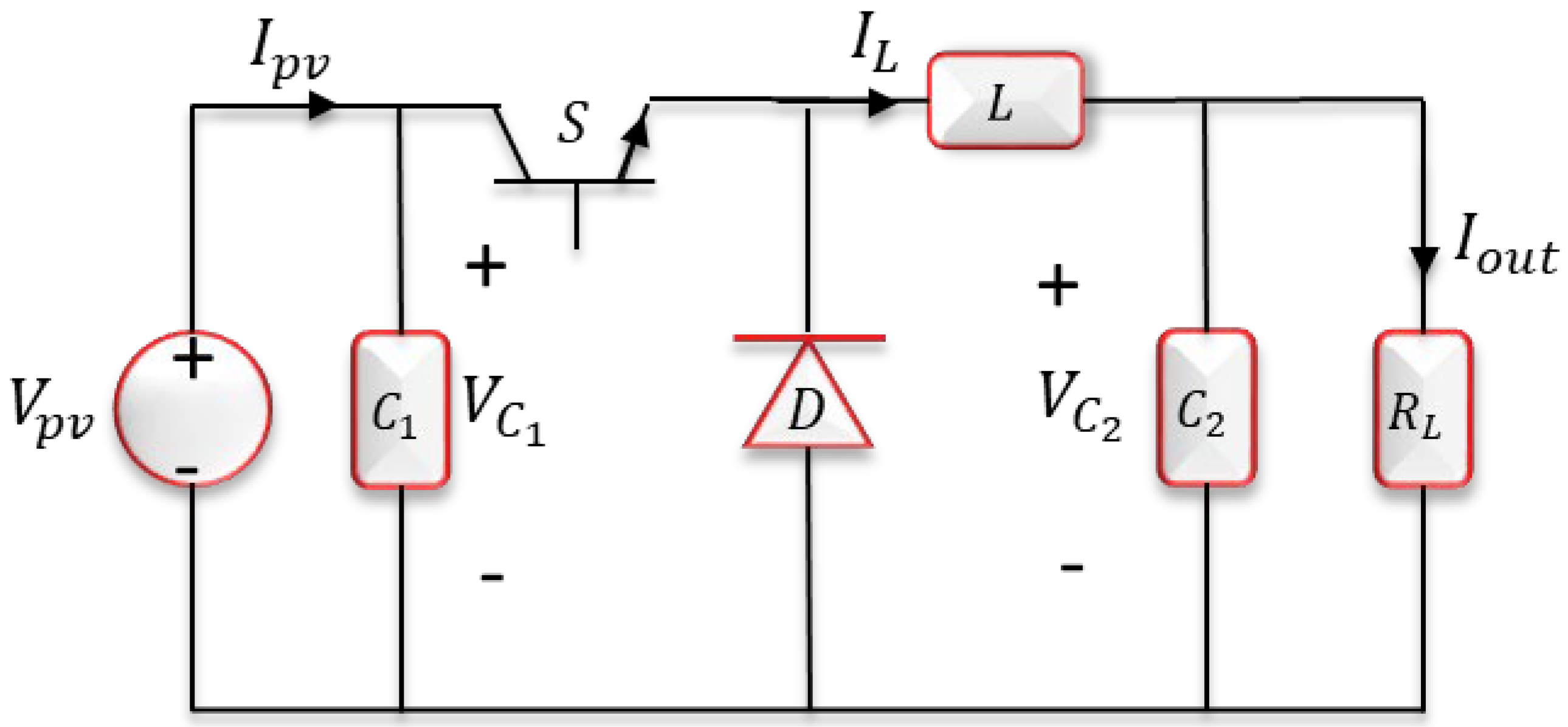
3. DC-DC Buck Converter
4. The Modified ADRC Design
4.1. The Proposed Tracking Differentiator
4.2. The Proposed Nonlinear Controllers
4.2.1. The Proposed Super Twisting Sliding Mode Controller (STC-SM)
4.2.2. The Proposed Nonlinear PID—Tracking Differentiator (NLPID-TD)
4.3. The Proposed NLESO
5. Stability of the Closed-Loop System
- and are bounded, which, and
- and are constant at the steady-state, which, and
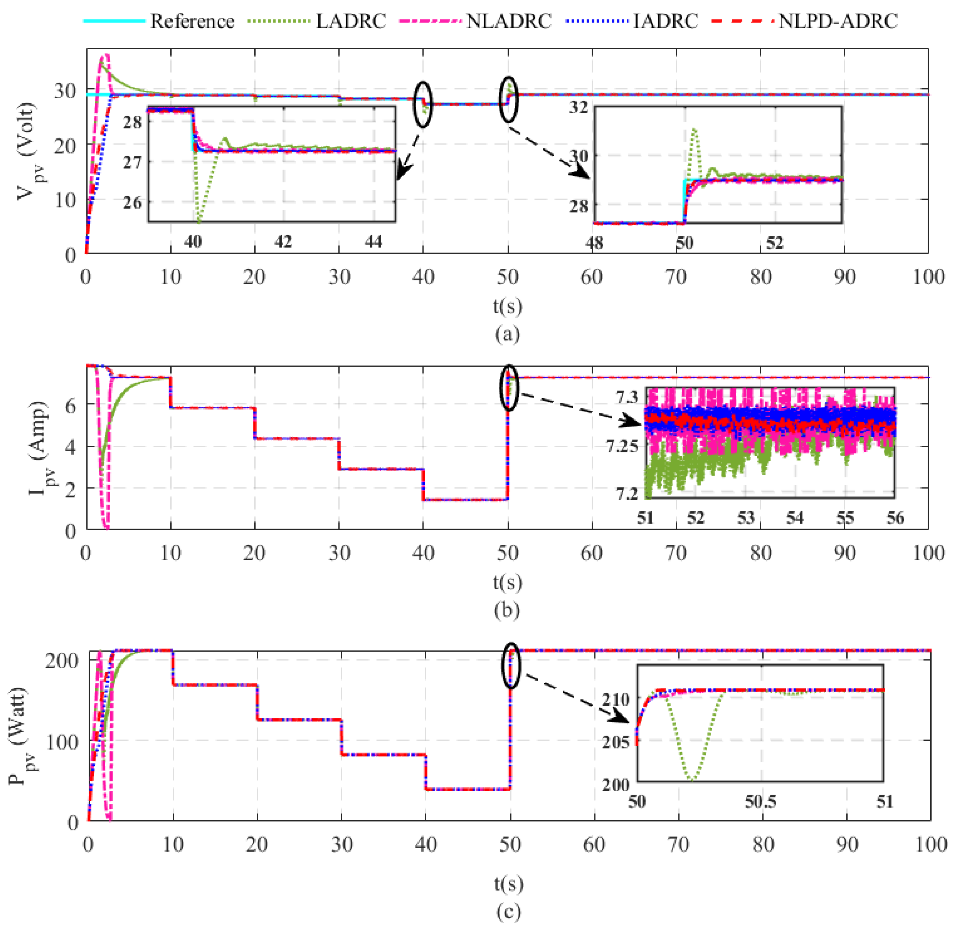
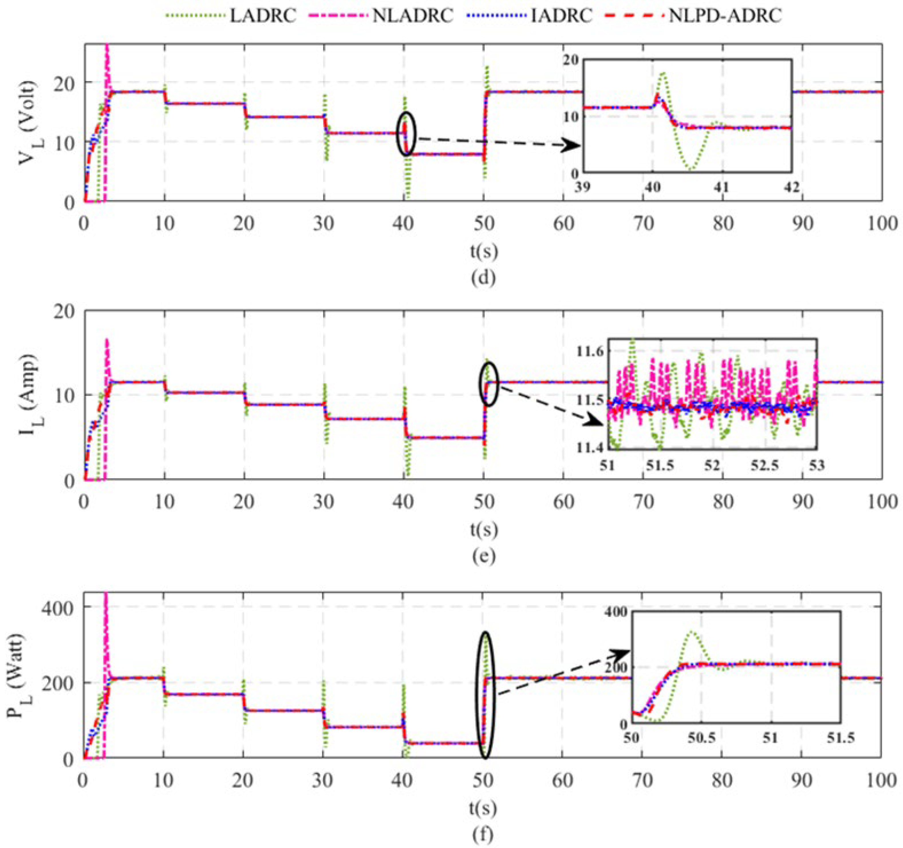
6. Simulation Results
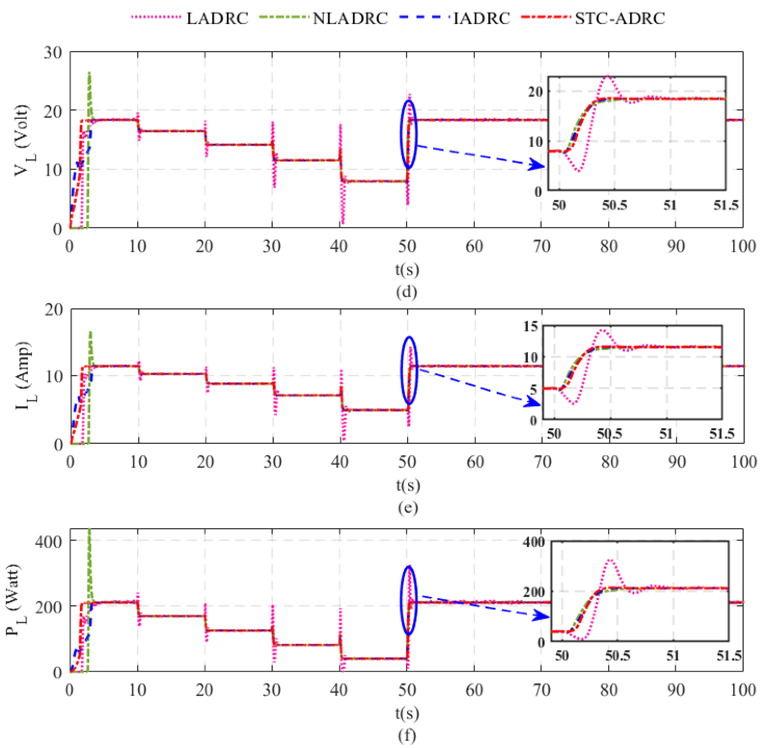
- Case study one: Irradiation changes with constant temperature at standard temperature conditions (STC).
- Case study two: Temperature changes with constant irradiation at standard temperature conditions (STC).
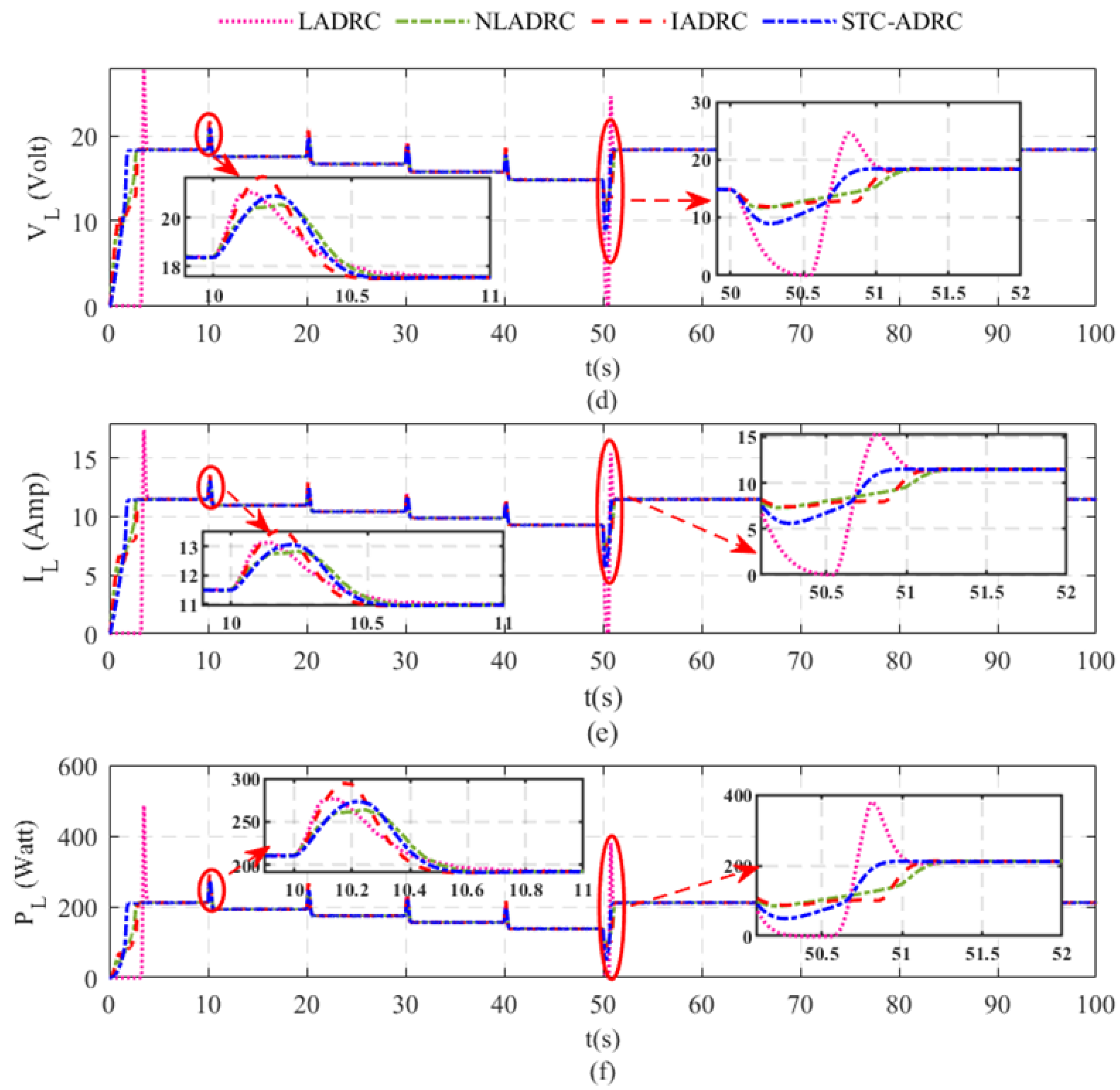
- Case study three: Load changes in both irradiation and temperature at standard temperature conditions (STC).
- i.
- Case study one. Irradiation changes with constant temperature at standard temperature conditions (STC).
- ii.
- Case study two. Temperature changes with constant irradiation at standard temperature conditions (STC).
- iii.
- Case study three: load change with both irradiation and temperature at standard temperature conditions (STC).
7. Conclusions
Author Contributions
Funding
Institutional Review Board Statement
Informed Consent Statement
Data Availability Statement
Acknowledgments
Conflicts of Interest
Appendix A
Appendix A.1. The Configuration of the ADRC Schemes
- 1.
- ADRC
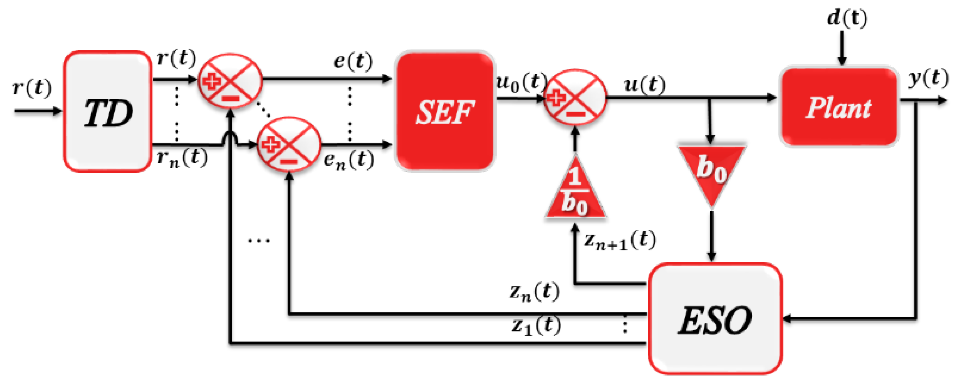
- 2.
- LADRC

- 3.
- IADRC, STC-ADRC, and NLPD-ADRC
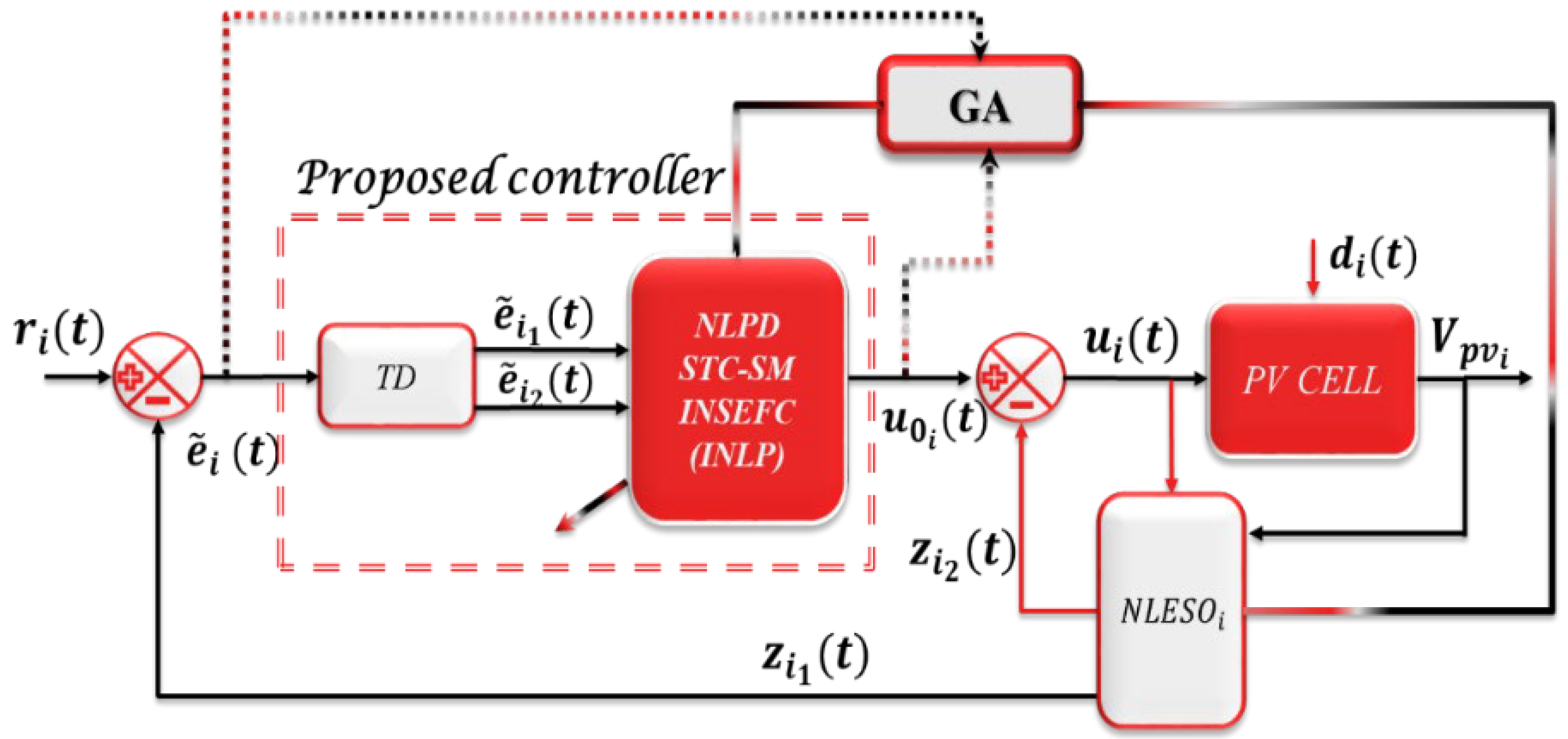
Appendix A.2. The Significance of the Different ADRC Schemes
References
- Nimrod, V.; Vázquez, J. Photovoltaic System Conversion. In Power Electronics Handbook; Butterworth-Heinemann: Oxford, UK, 2018. [Google Scholar] [CrossRef]
- Baba, A.O.; Liu, G.; Chen, X. Classification and Evaluation Review of Maximum Power Point Tracking Methods. Sustain. Futures 2020, 2, 100020. [Google Scholar] [CrossRef]
- Shalaby, R.; Ammar, H.H.; Azar, A.T.; Mahmoud, M.I. Optimal Fractional-Order Fuzzy-MPPT for solar water pumping system. J. Intell. Fuzzy Syst. 2021, 40, 1175–1190. [Google Scholar] [CrossRef]
- Fekik, A.; Azar, A.T.; Denoun, H.; Kamal, N.A.; Bahgaat, N.K.; Gorripotu, T.S.; Pilla, R.; Serrano, F.E.; Mittal, S.; Rana, K.P.S.; et al. Improvement of Fuel Cell MPPT Performance with a Fuzzy Logic Controller. In Advances in Nonlinear Dynamics and Chaos (ANDC); Academic Press: Cambridge, MA, USA, 2021; pp. 161–181. [Google Scholar] [CrossRef]
- Fekik, A.; Azar, A.T.; Kamal, N.A.; Serrano, F.E.; Hamida, M.L.; Denoun, H.; Yassa, N. Maximum Power Extraction from a Photovoltaic Panel Connected to a Multi-cell Converter. In Advances in Intelligent Systems and Computing, Proceedings of the International Conference on Advanced Intelligent Systems and Informatics 2020 (AISI 2020), Cairo, Egypt, 19–21 October 2020; Hassanien, A.E., Slowik, A., Snášel, V., El-Deeb, H., Tolba, F.M., Eds.; Springer: Cham, Switzerland, 2021; Volume 1261. [Google Scholar] [CrossRef]
- Rana, K.P.S.; Kumar, V.; Sehgal, N.; George, S.; Azar, A.T. Efficient Maximum Power Point Tracking in Fuel Cell Using the Fractional-Order PID Controller. In Advances in Nonlinear Dynamics and Chaos (ANDC); Academic Press: Cambridge, MA, USA, 2021; pp. 111–132. [Google Scholar] [CrossRef]
- Azar, A.T.; Serrano, F.E.; Flores, M.A.; Kamal, N.A.; Ruiz, F.; Ibraheem, I.K.; Humaidi, A.J.; Fekik, A.; Alain, K.S.T.; Romanic, K.; et al. Fractional-Order Controller Design and Implementation for Maximum Power Point Tracking in Photovoltaic Panels. In Advances in Nonlinear Dynamics and Chaos (ANDC); Academic Press: Cambridge, MA, USA, 2021; pp. 255–277. [Google Scholar] [CrossRef]
- Kamal, N.A.; Azar, A.T.; Elbasuony, G.S.; Almustafa, K.A.; Almakhles, D. PSO-Based Adaptive Perturb and Observe MPPT Technique for Photovoltaic Systems. In Advances in Intelligent Systems and Computing, Proceedings of the International Conference on Advanced Intelligent Systems and Informatics AISI 2019, Cairo, Egypt, 26–28 October 2019; Springer: Berlin/Heidelberg, Germany, 2020; Volume 1058, pp. 125–135. [Google Scholar]
- Ammar, H.H.; Azar, A.T.; Shalaby, R.; Mahmoud, M.I. Metaheuristic Optimization of Fractional Order Incremental Conductance (FO-INC) Maximum Power Point Tracking (MPPT). Complexity 2019, 2019, 7687891. [Google Scholar] [CrossRef]
- Ko, J.S.; Huh, J.H.; Kim, J.C. Overview of Maximum Power Point Tracking Methods for PV System in Micro Grid. Electronics 2020, 9, 816. [Google Scholar] [CrossRef]
- Sharma, R.S.; Katti, P.K. Perturb & observation MPPT algorithm for solar photovoltaic system. In Proceedings of the 2017 International Conference on Circuit, Power and Computing Technologies (ICCPCT), Kollam, India, 20–21 April 2017; pp. 1–6. [Google Scholar] [CrossRef]
- Kamran, M.; Muddassar, M.; Fazal, M.R.; Asghar, M.U.; Bilal, M.; Asghar, R. Implementation of improved Perturb & Observe MPPT technique with confined search space for standalone photovoltaic system. J. King Saud Univ.-Eng. Sci. 2020, 32, 432–441. [Google Scholar] [CrossRef]
- Dhaouadi, G.; Djamel, O.; Youcef, S.; Salah, C. Implementation of Incremental Conductance Based MPPT Algorithm for Photovoltaic System. In Proceedings of the 2019 4th International Conference on Power Electronics and their Applications (ICPEA), Elazig, Turkey, 25–27 September 2019; pp. 1–5. [Google Scholar] [CrossRef]
- Shang, L.; Guo, H.; Zhu, W. An improved MPPT control strategy based on incremental conductance algorithm. Prot. Control Mod. Power Syst. 2020, 5, 14. [Google Scholar] [CrossRef]
- Narendiran, S.; Sahoo, S.K.; Das, R.; Sahoo, A.K. Fuzzy logic controller based maximum power point tracking for PV system. In Proceedings of the 2016 3rd International Conference on Electrical Energy Systems (ICEES), Chennai, India, 17–19 March 2016; pp. 29–34. [Google Scholar] [CrossRef]
- Jyothy, L.P.N.; Sindhu, M.R. An Artificial Neural Network based MPPT Algorithm for Solar PV System. In Proceedings of the 2018 4th International Conference on Electrical Energy Systems (ICEES), Chennai, India, 7–9 February 2018; pp. 375–380. [Google Scholar] [CrossRef]
- Atawi, I.E.; Kassem, A.M. Optimal Control Based on Maximum Power Point Tracking (MPPT) of an Autonomous Hybrid Photovoltaic/Storage System in Micro Grid Applications. Energies 2017, 10, 643. [Google Scholar] [CrossRef]
- Darab, C.; Turcu, A.; Stefanescu, S.; Botezan, A.; Pica, C.; Pavel, S.; Abdourraziq, S. Robust control of MPPT of a PV cell. In Proceedings of the 2017 International Conference on Electromechanical and Power Systems (SIELMEN), Iasi, Romania, 11–13 October 2017; pp. 42–46. [Google Scholar] [CrossRef]
- Irwanto, M.; Zhe, L.W.; Ismail, B.; Baharudin, N.H.; Juliangga, R.; Alam, H.; Masri, M. Photovoltaic powered DC-DC boost converter based on PID controller for battery charging system. J. Phys. Conf. Ser. 2020, 1432, 012055. [Google Scholar] [CrossRef]
- Jeba, P.; Selvakumar, A.I. FOPID based MPPT for photovoltaic system. Energy Sources Part A Recovery Util. Environ. Eff. 2018, 40, 1591–1603. [Google Scholar] [CrossRef]
- Mirza, A.F.; Mansoor, M.; Ling, Q.; Khan, M.I.; Aldossary, O.M. Advanced Variable Step Size Incremental Conductance MPPT for a Standalone PV System Utilizing a GA-Tuned PID Controller. Energies 2020, 13, 4153. [Google Scholar] [CrossRef]
- Kler, V.; Rana, K.; Kumar, V. A Nonlinear PID Controller Based Novel Maximum Power Point Tracker for PV Systems. J. Frankl. Inst. 2018, 355, 7827–7864. [Google Scholar] [CrossRef]
- Pathak, D.; Sagar, G.; Gaur, P. An Application of Intelligent Non-linear Discrete-PID Controller for MPPT of PV System. Procedia Comput. Sci. 2020, 167, 1574–1583. [Google Scholar] [CrossRef]
- Deshpande, A.S.; Patil, S.L. Robust Observer-Based Sliding Mode Control for Maximum Power Point Tracking. J. Control. Autom. Electr. Syst. 2020, 31, 1210–1220. [Google Scholar] [CrossRef]
- Pandey, S.; Deshpande, A. Maximum Power Point Tracking Using Disturbance Observer-Based Sliding Mode Control for Estimation of Solar Array Voltage. Electr. Power Compon. Syst. 2020, 48, 148–161. [Google Scholar] [CrossRef]
- Han, J. From PID to Active disturbance rejection control. Ind. Electron. 2009, 56, 900–906. [Google Scholar] [CrossRef]
- Gao, Z.; Li, S.; Zhou, X.; Ma, Y.; Zhao, J. A new maximum power point tracking method for PV system. In Proceedings of the 2017 29th Chinese Control and Decision Conference (CCDC), Chongqing, China, 28–30 May 2017; pp. 544–548. [Google Scholar] [CrossRef]
- Benrabah, A.; Khoucha, F.; Raza, A.; Xu, D. A New Robust Control for Grid Connected Photovoltaic Systems Based on Active Disturbance Rejection Control. J. Electr. Syst. 2019, 15, 81–95. [Google Scholar]
- Ramirez, E.G.; Barbosa, A.M.; Ordaz, M.A.C.; Ramirez, G.G. FPGA-based active disturbance rejection control and maximum power point tracking for a photovoltaic system. Int. Trans. Electr. Energy Syst. 2020, 30, e12398. [Google Scholar] [CrossRef]
- Zhou, X.; Liu, Q.; Ma, Y.; Xie, B. DC-Link Voltage Research of Photovoltaic Grid-Connected Inverter Using Improved Active Disturbance Rejection Control. IEEE Access 2021, 9, 9884–9894. [Google Scholar] [CrossRef]
- Hou, G.; Ke, Y.; Huang, C. A flexible constant power generation scheme for photovoltaic system by error-based active disturbance rejection control and perturb & observe. Energy 2021, 237, 121646. [Google Scholar] [CrossRef]
- Rashid, M.H. Power Electronic Handbook, 4th ed.; Elsevier: Amsterdam, The Netherlands, 2018. [Google Scholar] [CrossRef]
- Toumi, D.; Benattous, D.; Ibrahim, A.; Abdul-Ghaffar, H.I.; Obukhov, S.; Aboelsaud, R.; Labbi, Y.; Diab, A.A.Z. Optimal design and analysis of DC-DC converter with maximum power controller for stand-alone PV system. Energy Rep. 2021, 7, 4951–4960. [Google Scholar] [CrossRef]
- Baharudin, N.; Mansur, T.M.N.T.; Abdul- Hamid, F.; Ali, R.; Misrun, M.R. Topologies of DC-DC converter in solar PV applications. Indones. J. Electr. Eng. Comput. Sci. 2017, 8, 368–374. [Google Scholar] [CrossRef]
- Pandiarajan, N.; Muthu, R. Mathematical modeling of photovoltaic module with Simulink. In Proceedings of the 2011 1st International Conference on Electrical Energy Systems, Chennai, India, 3–5 January 2011; pp. 258–263. [Google Scholar] [CrossRef]
- Iftikhar, R.; Ahmad, I.; Arsalan, M.; Naz, N.; Ali, N.; Armghan, H. MPPT for Photovoltaic System Using Nonlinear Controller. Int. J. Photoenergy 2018, 2018, 6979723. [Google Scholar] [CrossRef]
- Zeb, K.; Busarello, T.D.C.; Islam, S.U.; Uddin, W.; Raghavendra, K.V.G.; Khan, M.A.; Kim, H.J. Design of Super Twisting Sliding Mode Controller for a Three-Phase Grid-connected Photovoltaic System under Normal and Abnormal Conditions. Energies 2020, 13, 3773. [Google Scholar] [CrossRef]
- Shtessel, Y.; Fridman, L.; Edwards, C.; Levant, A. Sliding Mode Control and Observation; Springer: New York, NY, USA; Heidelberg, Germany; Dordrecht, The Netherlands; London, UK, 2014; ISBN 978-0-8176-4892-3/978-0-8176-4893-0. [Google Scholar] [CrossRef]
- Gao, Z. Scaling and bandwidth-parameterization based controller tuning. In Proceedings of the 2003 American Control Conference, Denver, CO, USA, 4–6 June 2003; pp. 4989–4996. [Google Scholar] [CrossRef]
- Zheng, Q. On Active Disturbance Rejection Control; Stability Analysis and Applications in Disturbance Decoupling Control. Ph.D. Thesis, Cleveland State University, Cleveland, OH, USA, 2009. Available online: https://engagedscholarship.csuohio.edu/etdarchive/324 (accessed on 20 June 2022).
- Khalil, K.H. Nonlinear Control, Global Edition; Pearson Education: Essex, UK, 2015. [Google Scholar]
- Najm, A.A.; Ibraheem, I.K. Altitude and Attitude Stabilization of UAV Quadrotor System using Improved Active Disturbance Rejection Control. Arab. J. Sci. Eng. 2020, 45, 1985–1999. [Google Scholar] [CrossRef]
- Arsalan, M.; Iftikhar, R.; Ahmad, I.; Hasan, A.; Sabahat, K.; Javeria, A. MPPT for photovoltaic system using nonlinear backstepping controller with integral action. Sol. Energy 2018, 170, 192–200. [Google Scholar] [CrossRef]
- Abdul-Adheem, W.R.; Ibraheem, I.K. From PID to Nonlinear State Error Feedback Controller. Int. J. Adv. Comput. Sci. Appl. (IJACSA) 2017, 8, 312–322. [Google Scholar] [CrossRef]
- Abdul-Adheem, W.R.; Ibraheem, I.K. Improved Sliding Mode Nonlinear Extended State Observer based Active Disturbance Rejection Control for Uncertain Systems with Unknown Total Disturbance. Int. J. Adv. Comput. Sci. Appl. (IJACSA) 2016, 7, 80–93. [Google Scholar]





| Parameters | Description | Value | Unit |
|---|---|---|---|
| Boltzmann constant | |||
| Electron charge | |||
| Short circuit current at STC | |||
| Open circuit voltage at STC | |||
| Temperature voltage constant | |||
| Temperature current constant | |||
| Diode ideality factor | |||
| Temperature at STC | |||
| Irradiation at STC | |||
| Band-gap energy | |||
| Series resistance | |||
| Parallel resistance | |||
| Number of cells connected in series | |||
| Number of cells connected in parallel | |||
| Number of modules connected in series |
| Parameters | Description | Value | Unit |
|---|---|---|---|
| The input capacitor | |||
| The output capacitor | |||
| Inductor | |||
| Load resistance | |||
| Switching frequency |
| Performance Index | Description | Mathematical Representation |
|---|---|---|
| Integral Time Absolute Error | ||
| Integral Absolute of the control signal | ||
| Integral Square of the control signal |
| Scheme | ADRC Parts | ||
|---|---|---|---|
| TD | SEF | ESO | |
| LADRC | are the proportional, integral, and derivative gains, respectively. | The LESO can be expressed as follows: | |
| ADRC | The NLSEF of [33] can be expressed as follows: | ||
| IADRC | The INLSEF of [44] can be expressed as: | The SMESO of [45] can be expressed as: are the nonlinear function gains and are tuning parameters. | |
| STC-ADRC | Equation (12) | The proposed STC-SM of Equations (12) and (13). | Proposed NLSEO of Equations (16) and (17). |
| NLPD-ADRC | Equation (12) | The proposed NLPD of Equation (33). | Proposed NLSEO of Equation (18). |
| ADRC Unit | Parameter | Value | Parameter | Value |
|---|---|---|---|---|
| LPID | 1 × 10⁻⁹ | |||
| LESO |
| ADRC Unit | Parameter | Value | Parameter | Value |
|---|---|---|---|---|
| NLSEF | ||||
| LESO | ||||
| ADRC Unit | Parameter | Value | Parameter | Value |
|---|---|---|---|---|
| INLSEF (NLPI) | ||||
| SMESO | ||||
| ADRC Unit | Parameter | Value | Parameter | Value |
|---|---|---|---|---|
| NLPD | ||||
| TD | ||||
| NLESO | ||||
| ADRC Unit | Parameter | Value | Parameter | Value |
|---|---|---|---|---|
| STC-SM | ||||
| TD | ||||
| NLESO | ||||
| Performance Index | LADRC | ADRC | IADRC | NLPD-ADRC | STC-ADRC |
|---|---|---|---|---|---|
Publisher’s Note: MDPI stays neutral with regard to jurisdictional claims in published maps and institutional affiliations. |
© 2022 by the authors. Licensee MDPI, Basel, Switzerland. This article is an open access article distributed under the terms and conditions of the Creative Commons Attribution (CC BY) license (https://creativecommons.org/licenses/by/4.0/).
Share and Cite
Azar, A.T.; Abed, A.M.; Abdulmajeed, F.A.; Hameed, I.A.; Kamal, N.A.; Jawad, A.J.M.; Abbas, A.H.; Rashed, Z.A.; Hashim, Z.S.; Sahib, M.A.; et al. A New Nonlinear Controller for the Maximum Power Point Tracking of Photovoltaic Systems in Micro Grid Applications Based on Modified Anti-Disturbance Compensation. Sustainability 2022, 14, 10511. https://doi.org/10.3390/su141710511
Azar AT, Abed AM, Abdulmajeed FA, Hameed IA, Kamal NA, Jawad AJM, Abbas AH, Rashed ZA, Hashim ZS, Sahib MA, et al. A New Nonlinear Controller for the Maximum Power Point Tracking of Photovoltaic Systems in Micro Grid Applications Based on Modified Anti-Disturbance Compensation. Sustainability. 2022; 14(17):10511. https://doi.org/10.3390/su141710511
Chicago/Turabian StyleAzar, Ahmad Taher, Azher M. Abed, Farah Ayad Abdulmajeed, Ibrahim A. Hameed, Nashwa Ahmad Kamal, Anwar Jaafar Mohamad Jawad, Ali Hashim Abbas, Zainab Abdulateef Rashed, Zahraa Sabah Hashim, Mouayad A. Sahib, and et al. 2022. "A New Nonlinear Controller for the Maximum Power Point Tracking of Photovoltaic Systems in Micro Grid Applications Based on Modified Anti-Disturbance Compensation" Sustainability 14, no. 17: 10511. https://doi.org/10.3390/su141710511
APA StyleAzar, A. T., Abed, A. M., Abdulmajeed, F. A., Hameed, I. A., Kamal, N. A., Jawad, A. J. M., Abbas, A. H., Rashed, Z. A., Hashim, Z. S., Sahib, M. A., Ibraheem, I. K., & Thabit, R. (2022). A New Nonlinear Controller for the Maximum Power Point Tracking of Photovoltaic Systems in Micro Grid Applications Based on Modified Anti-Disturbance Compensation. Sustainability, 14(17), 10511. https://doi.org/10.3390/su141710511


