Article

Study on the Horizontal Bearing Characteristic of a New Type of Offshore Rubber Airbag Branch Pile

1
College of Civil Engineering, Hebei University of Engineering, Handan 056006, China
2
State Key Laboratory of Coastal and Offshore Engineering, Dalian University of Technology, Dalian 116024, China
3
College of Civil Engineering, Qingdao University of Technology, Qingdao 266033, China
*
Author to whom correspondence should be addressed.
Sustainability 2022, 14(12), 7331; https://doi.org/10.3390/su14127331
Submission received: 25 May 2022 / Revised: 11 June 2022 / Accepted: 12 June 2022 / Published: 15 June 2022

Abstract

:
In this work, a new type of marine rubber airbag branch pile has been presented, and the influences of the exposed length L0 of the pile, size of rubber airbag branch and depth S0 of rubber airbag branch embedded in soil on the horizontal bearing capacity of the pile, have been investigated using numerical simulations. Simulation results were used to modify the eigenvalue equations of the horizontal bearing capacity. The results also showed that reverse displacement and the bending moment of the rubber airbag branch pile were lower in pipe piles with larger diameters, and the horizontal bearing capacity was more stable. At small horizontal displacements of the pile top, horizontal bearing capacities of large-diameter pipe piles were slightly higher, while for the pile’s top horizontal displacements of above 10 mm, horizontal bearing capacities of rubber airbag branch piles became significantly greater than those of the large-diameter pipe piles. Based on assumptions, the calculation equations of vacuum negative pressure and friction force between the rubber airbag branch and soil were derived. The equations for calculating the characteristic horizontal bearing capacities of rubber airbag branch piles were also derived and were modified based on simulation results. The calculation results confirmed the improvement in the accuracy of the modified equations.

1. Introduction

With the continuous development and exhaustion of marine resources, particularly the invention of offshore wind power generators as a novel energy source, there is little harmful impact on the environment and is economical and practical; therefore, wind power generators have become extremely popular around the world. Today, about two-thirds of single pile foundations are being used to resist the lateral loads created by sea winds, currents and waves as well as seismic waves. The impact forces of these loads have great impacts on pile horizontal displacements [1]. Based on the analytical results obtained for the horizontal bearing capacities of marine high pile foundations, pile exposed lengths and pile foundation forms were found to have great influences on the horizontal bearing capacities of these structures. In addition, soil resistance around piles varied nonlinearly with depth. Obtaining an accurate calculation of the mechanical characteristics of pile-soil is difficult [2,3]. Therefore, in this research, the form of offshore pile foundations was improved to change their horizontal force transfer mechanisms, which provided a solution for the problem of insufficient horizontal bearing capacity and a large displacement of high pile foundations.
Currently, theoretical models, in situ test methods and finite element numerical models are often used for the investigation of horizontal bearing characteristics of pile foundations. However, finite element numerical simulations are widely applied because they are not restricted by the environmental conditions of the field [4,5]. Jeong [6] investigated the load distribution and deformation of drilling wellbores under lateral loads through field load tests and P-Y curves, and found that the main factor affecting drilling precision was wellbore stiffness. Mahdi Taha K et al. [7] In order to determine the advantages of the pile with wings, four embedded ratios were used to model the flexible and rigid pile types with different wings and sizes. The results showed that adding wing plates to the pile can improve the lateral force of the pile and greatly reduce the lateral deflection of the pile. Poorjafar Aysan et al. [8] summarize the small-scale laboratory simulation results of pile behavior under a lateral load, considering parameters, such as a short or long pile, a single or group pile, spacing and stiffness or flexibility. The results showed that the short pile had rigid movement, the displacement of the surrounding soil occurred along the total length of the pile, and the pile rotated around a point; however, the long pile had flexible movement in the long part of the pile. Francisco González et al. [9] proposed an equivalent linear boundary element–finite element model that considered soil degradation at the pile–soil interface, which was used to approximate the lateral time-harmonic response of piles. Amar Bouzid Djillali [10] proposed a new P-Y formula containing a new P-Y shape and a new initial stiffness and coded it in the existing Winkler computer program. Through the study of three cases in the literature, the results of the new formula were verified. Deendayal Rathod et al. [11] carried out a series of indoor model tests on instrumented model piles embedded in slopes with different length–diameter ratios. Endi et al. [12] found that the P-Y curves obtained, based on the API standards, were safe, while the “M” method was unsafe; however, the results obtained from the “M” method were closer to the experimentally measured values. Ahmed Sahli et al. [13] discuss the compilation of the calculation program for the safety modeling and verification of the pile limit state in the current structural foundation. Accordingly, the reliability technology is applied to the probability analysis of piles, where the finite element method (FEM) is combined with the boundary element method (BEM), and Mindlin’s basic solution is used to model the soil by boundary element, which is suitable for considering three-dimensional infinite half-space.
The cross-section shape of the pile, theoretical analysis and calculation method of pile–soil interactions all have a great influence on the design bearing capacity of the pile. At present, there are few types of research on reducing the horizontal displacement of the pile by applying transverse binding force, and the method of changing the cross-section shape of the pile cannot weaken the relative stiffness of the pile and soil. Although the variable section pile can improve the horizontal bearing capacity of the pile, it is easy to cause the pile-soil separation phenomenon at the variable section of the pile under a long-term cyclic load. Moreover, the study shows that the P-Y curve is more conservative than the M method, and the M method is closer to reality. Therefore, in the current work, a new type of rubber capsule supporting piles was proposed. The ABAQUS software was used to analyze the horizontal bearing characteristics of different rubber airbag branch pile sizes, buried depths S0, exposed lengths of pile above the soil surface L0 and horizontal displacements of pile top. The results were compared with those obtained for large-diameter pipe piles. On this basis, the equations for calculating the characteristic values of the horizontal bearing capacity of rubber airbag branch piles were derived.

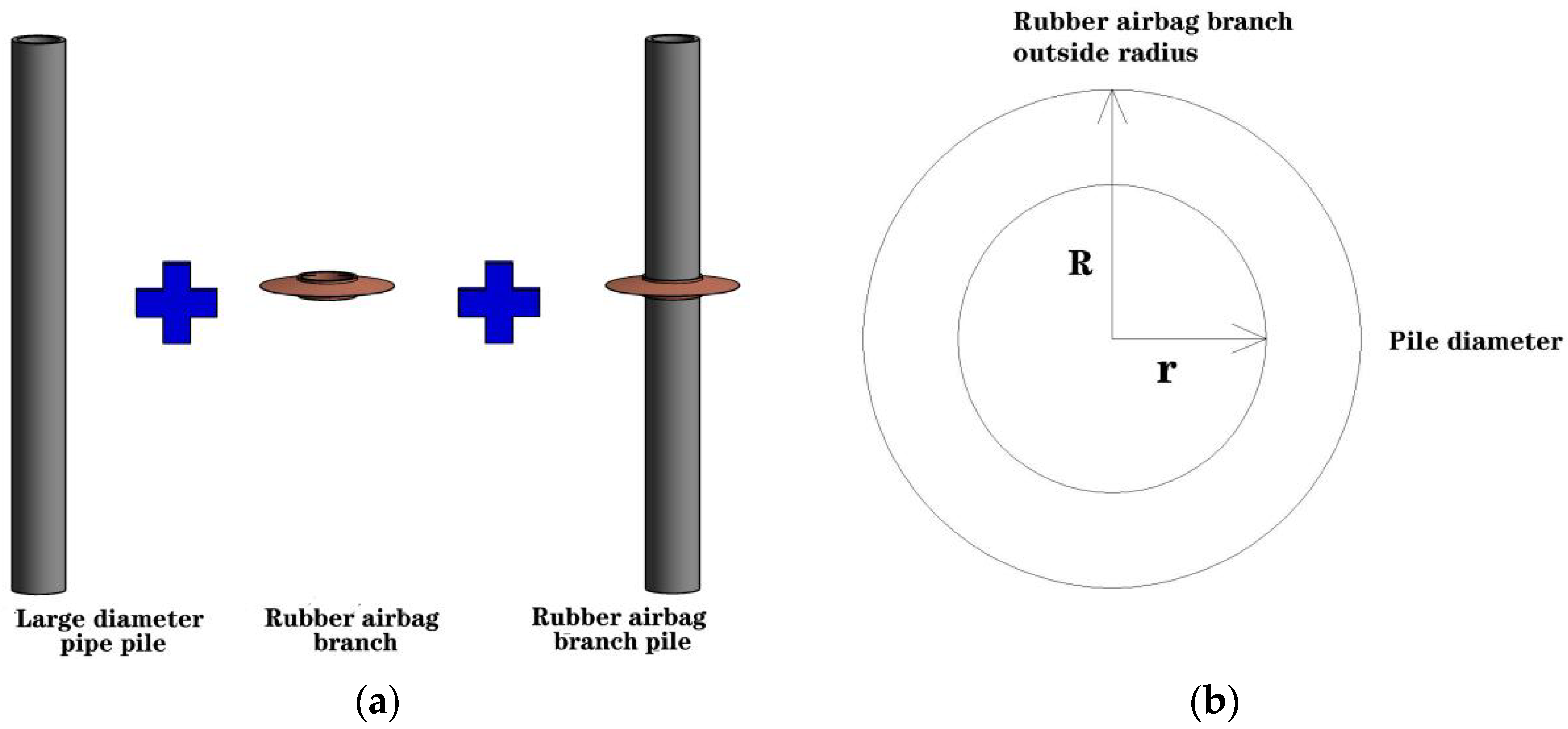
2. Horizontal Bearing Mechanism of Rubber Air Bag Branch Piles

Rubber airbag branch piles are mainly composed of large-diameter pipe piles and hollow rubber airbag branches. In Figure 1, R is the external radius of the rubber sac ascot and r is the pile diameter. Due to the characteristics of rubber materials, such as high density, low rigidity and easy deformation [14,15] and the physical and mechanical characteristics of marine muddy soft soils with low permeability, the rubber airbag branch compresses soil when it is pressurized in the soil. The air and water in the joint between the surface of the rubber airbag branch and soil are gradually eliminated, and the air pressure is decreased, resulting in negative vacuum pressure. When the pile body is subjected to a horizontal load, the soil and rubber airbag branch work cooperatively and a mutual suction-and-pull action occurs, resulting in the generation of resistance to the horizontal load and an increase in the horizontal bearing capacity of piles. In addition, the cross-sectional areas of rubber airbag branches are larger than those of pile bodies. A relatively closed space is created from the pile end to the rubber airbag branch. When pile bodies undergo horizontal displacement, a vacuum negative pressure is generated on the pile side opposite to the direction of displacement to resist the displacement of the pile, which acts on the pile body in the form of an arc transverse surface load. Because of the circular shape of the rubber airbag branch, no matter whether the pile top is subjected to the load from any horizontal direction, the rubber airbag branch generates lateral restraint on the pile body.
Due to the favorable elastic deformation properties of rubber airbag branch materials, it is difficult for the pile to fully play its role in very small pile displacements. Therefore, due to bearing demand, fine steel wires could be embedded to improve the rubber airbag branch tensile’s bearing capacity to decrease large tensile deformations due to the elastic properties of rubber materials during tension.

3. Finite Element Numerical Simulation and Result Analysis

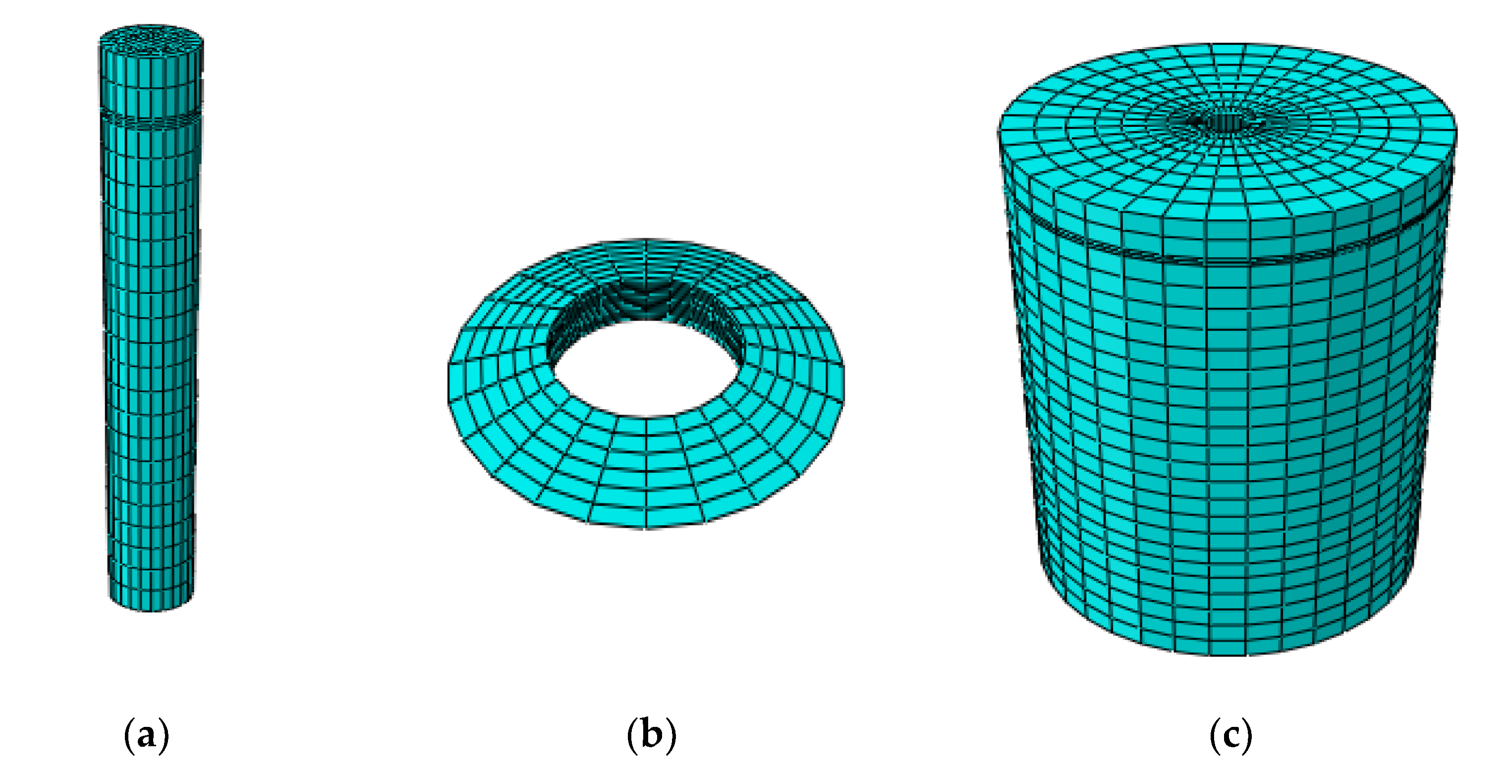
3.1. Establishment of Finite Element Model of Rubber Airbag Branch Pile

The ABAQUS finite element simulation software was applied to establish a rock-socketed pile foundation. The established pile was a large-diameter pipe pile with outer and inner diameters of 5 and 3.25 m, respectively, a wall thickness of 1.75 m and a buried depth of 55 m. Moreover, the rock-socketed depth was 5 m and the pile body exposed lengths L0 were 0, 5, 10, 15 and 20 m. To decrease the amount of stress transferred from the pile to the soil boundary through a horizontal load, a cylindrical model with a radius of 25 m and depth of 70 m, where 0–50 m was a clay layer and 50–70 m was a rock layer, was adopted. The Mohr–Coulomb constitutive and linear elastic constitutive models were used for the simulation of the clay layer. A linear elastic constitutive model was applied for rock stratum, pile and rubber airbag branch. In order to avoid relative slippage, the pile-rubber airbag branch and pile bottom-rock layer contacts had to be bound. A penalty function was applied for the rubber airbag branch surface-soil body and pile body-soil body contacts. Pile-rock surface contact was considered to be a rough contact. To realize the transformation of pile top horizontal displacement from a small horizontal displacement to a large horizontal displacement, the horizontal displacement range of the pile top was considered as 0~50 mm with an interval of 2 mm. Table 1 summarizes the physical and mechanical parameters of the soil layer, rubber airbag branch and pile, and Figure 2 shows the mesh division of the model.

3.2. Simulation Conditions

By analyzing the horizontal loading mechanism of rubber airbag branch piles, it was concluded that their horizontal bearing capacities were mainly affected by the pile body exposed length L0, rubber airbag branch size and buried depth S0 in soil. In this section, these three influencing factors are compared and analyzed under the following combination of working conditions.
The exposed length of high pile foundations is generally long. Without an external force constraint, pile top displacement, due to a horizontal load, is relatively large and bending deformations can easily occur. By comparing rubber airbag branch piles and large-diameter pipe piles at various exposed lengths L0, the effect of L0 on horizontal bearing capacities was explored when horizontal displacement deformation occurred on the pile top. Table 2 summarizes the specific combination of working conditions for this test.
It was found that an increase in the height and outer radius of rubber airbags increased soil contact areas, which affected the negative vacuum pressure and friction force of rubber airbag branches. In addition, with the increase in the rubber airbag branch height, the soil around the pile was separated, affecting the pile’s horizontal bearing capacity. In order to evaluate the effect of the rubber airbag branch size on pile top horizontal bearing capacities, both L0 and S0 were fixed at 5 m. Table 3 and Table 4 summarize the combined working conditions of the test.
The buried depth S0 of rubber airbag branch in the soil also affected pile horizontal bearing capacity; especially, horizontal reactions of rubber airbag branch at various pile body positions affected pile bending performance. In order to explore the effects of rubber airbag branch on the two properties of the buried depth S0 of rubber airbag branch and the length L0 of pile above the soil surface, the relationship between pile top horizontal displacement and bearing capacity, and that between pile top horizontal displacement and pile body bending moment were compared and analyzed. Table 5 summarizes the combined conditions applied in this experiment.

3.3. Result Analysis

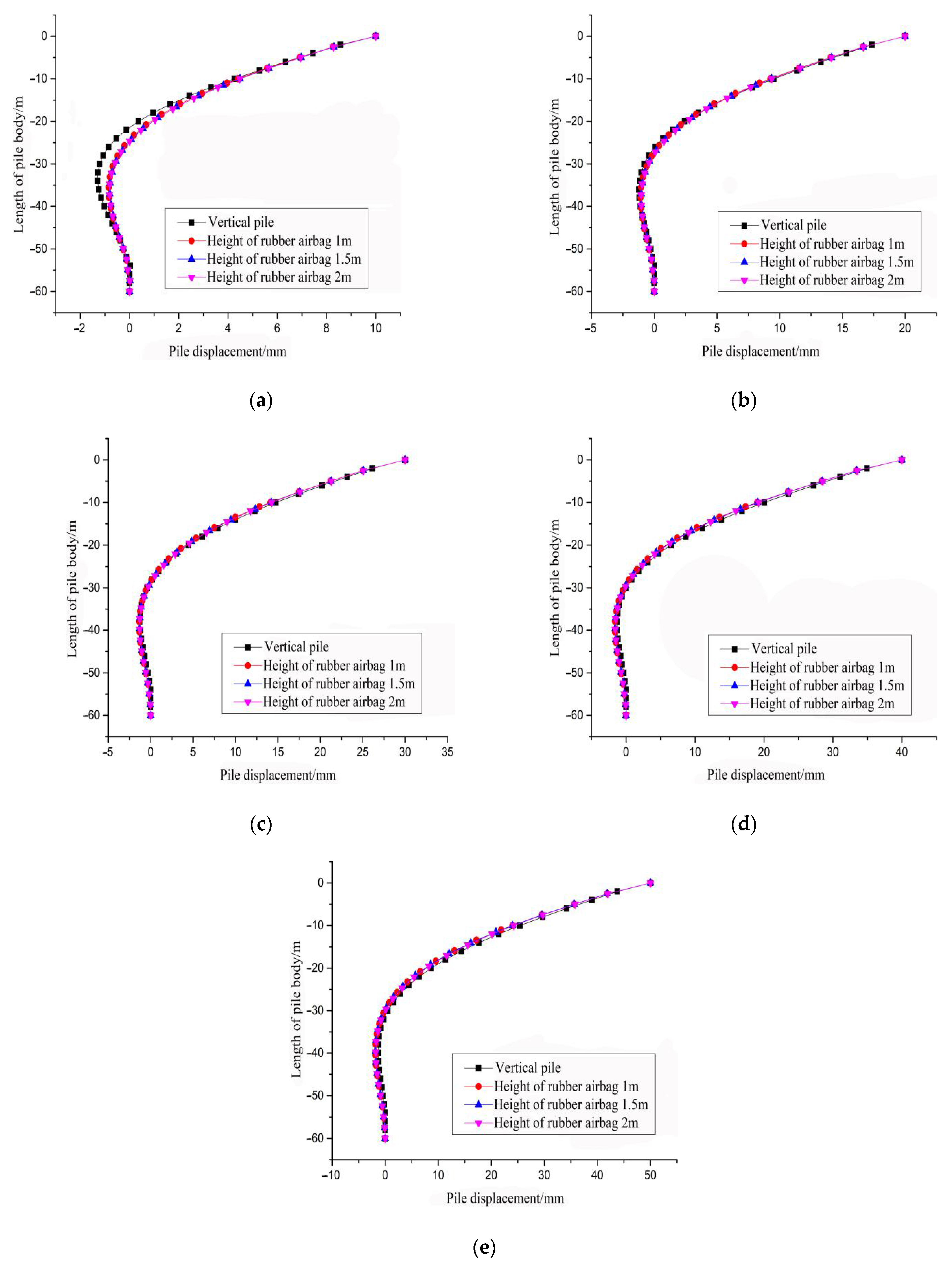
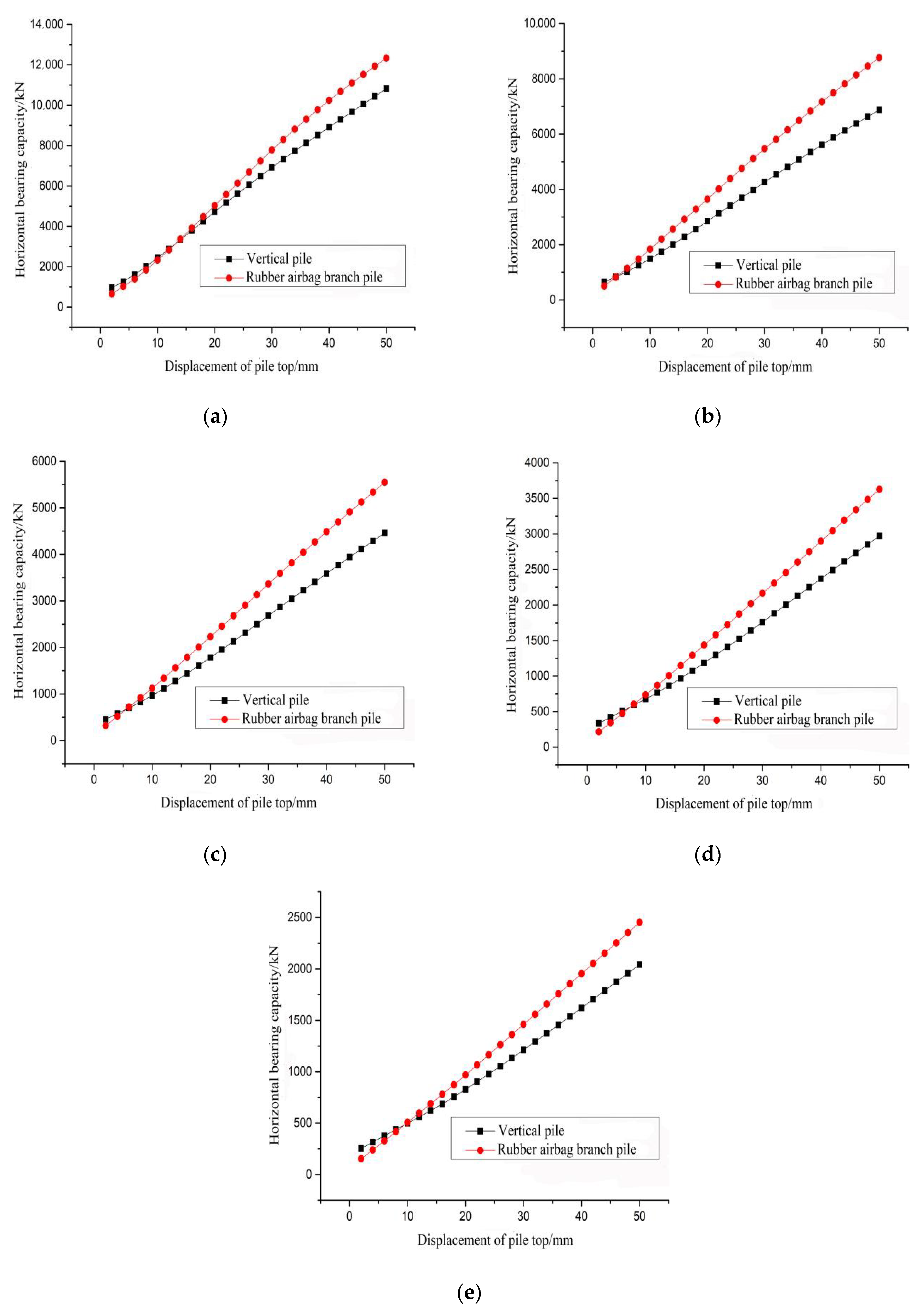
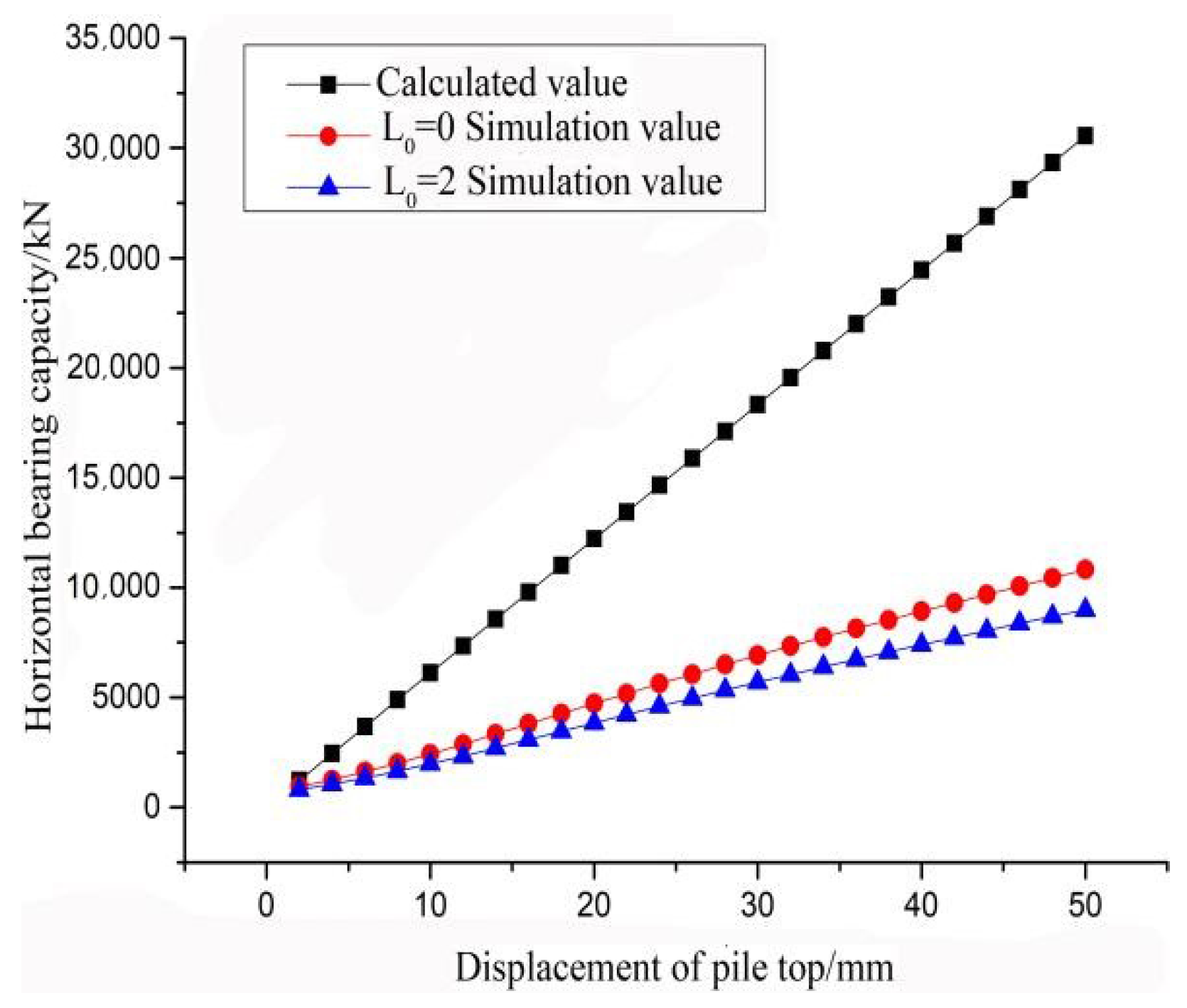
3.3.1. Comparative Analysis of Different Exposed Pile Lengths

According to the working conditions given in Table 2, at the pile top horizontal displacements of 2 mm~50 mm, the comparison results of the exposed lengths L0 of the straight pile and rubber airbag branch pile outside the pile were different, as shown in Figure 3. It was seen that an increase in L0 decreased the pile horizontal bearing capacity. The pile top horizontal bearing capacity was increased with the increase in pile top horizontal displacement at a growth rate of an almost straight line; also, the growth rate of the horizontal bearing capacity of rubber airbag branch piles was greater than that of the large-diameter pipe piles. However, the horizontal bearing capacity of rubber airbag branch piles with small pile top horizontal displacements was smaller than that of the large-diameter pipe piles. In Figure 3a, at a pile top horizontal displacement of 12 mm, the horizontal bearing capacities of rubber airbag branches and straight piles were 2827 and 2880 kN, respectively. At a pile top horizontal displacement of 14 mm, the horizontal bearing capacities of rubber airbag branches and vertical piles were 3369 and 3364 kN, respectively. It was seen that the horizontal bearing capacity of the rubber airbag branch pile was higher than that of the large-diameter pipe piles at pile top displacements of 12–14 mm. In Figure 3b–e, the pile top horizontal displacements were 4~6, 4~6, 6~8 and 8~10 mm, respectively. The bearing capacities of the rubber airbag branch piles exceeded those of vertical piles. At L0 values of 0, 5, 10, 15 and 20 m, the horizontal displacements of rubber airbag branches and large-diameter pipe piles reached 50 mm and the difference in the horizontal loads they were able to carry were 1510, 1891, 1090, 656 and 410 kN, respectively. The obtained results showed that by increasing L0, the horizontal bearing capacity of the rubber airbag branch pile was first increased and then decreased under large pile top displacements.
Based on the five comparison results mentioned above, the effect of L0 on horizontal displacement was generated from the fact that when the pile top was exposed to horizontal loads, the flexural rigidity of the pile first played a role and then transferred to the soil under the constraint of the soil reaction around the pile. However, the length L0 of the pile above the soil surface directly depended on flexural strength, which resulted in a decreased horizontal bearing capacity of the pile. As the length of the pile’s exposed part was increased, the distance of horizontal load transfer to soil was increased and the extension of time for the reaction of soil around the pile to exert its effect along with the horizontal bearing capacity of the pile was also decreased. When the rubber airbag branch entered the soil along with the pile, some parts of the soil and pile were separated. In the process of pile top horizontal load transfer, part of the soil reaction around the pile was missing. Therefore, when the pile top horizontal load was transferred to the rubber airbag branch, the rubber airbag branch first produced tensile deformation with pile body displacement direction and, then, extrusion deformation occurred in the opposite direction of the pile body horizontal displacement. In this process, the horizontal load-bearing capacity of rubber airbag branch piles was not high enough to make up for the loss of soil reaction around the pile and the horizontal bearing capacity of rubber airbag branch piles was less than those of large-diameter pipe piles. However, as pile top horizontal displacement occurred, the tensile and extrusion deformations of rubber airbag branches gradually reached their limit values. Pile horizontal bearing capacity was increased due to the horizontal load resistance generated by rubber airbag branches.

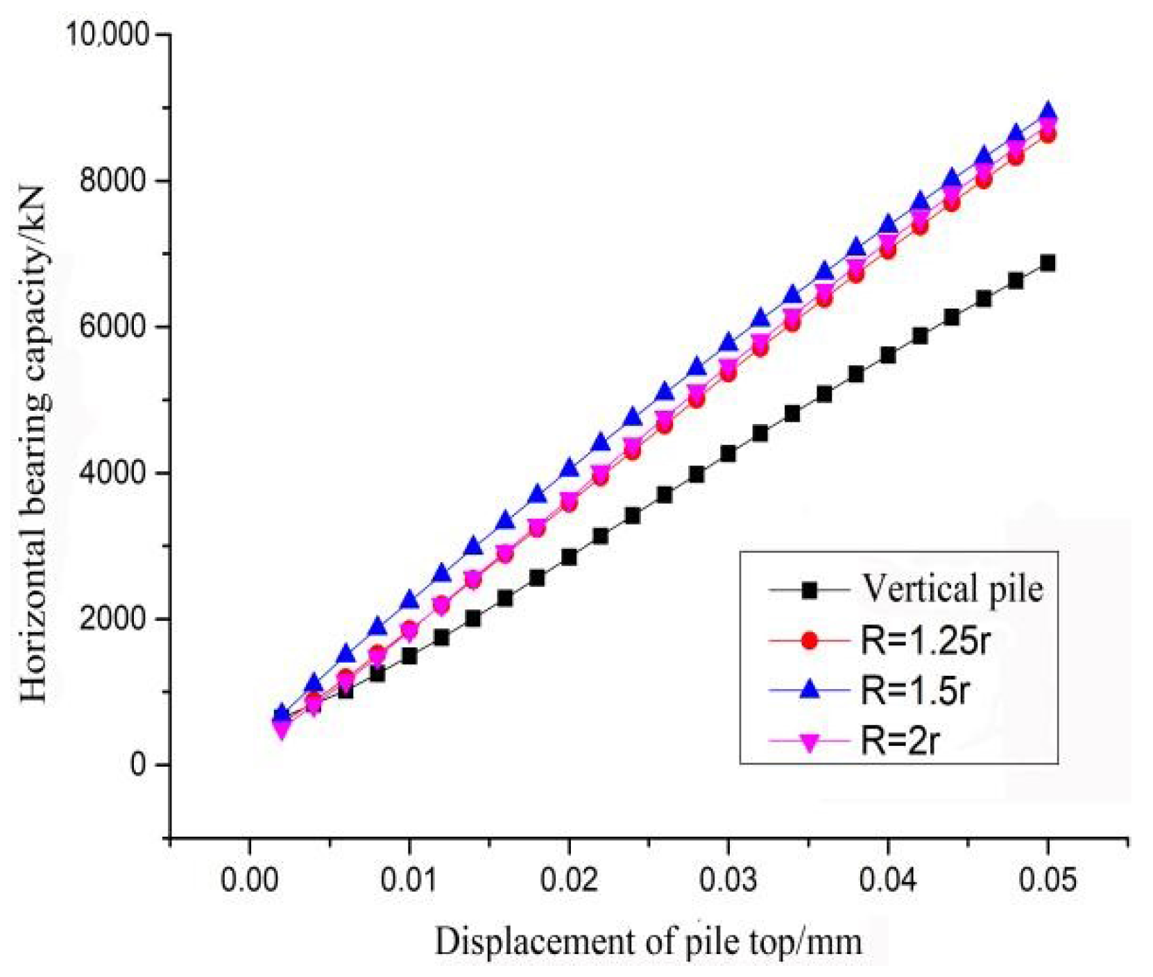
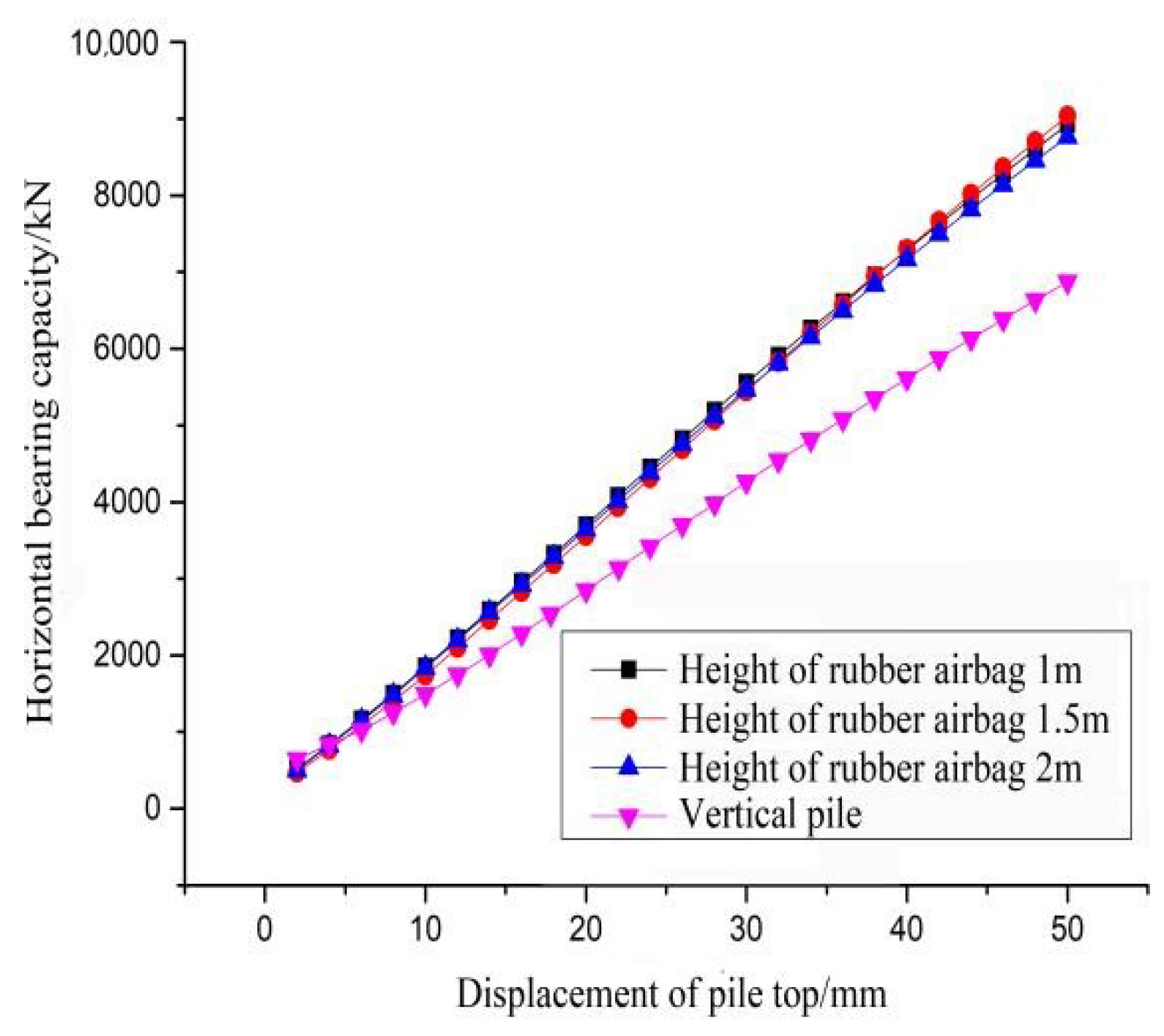
3.3.2. Comparative Analysis of Different Sizes of Rubber Airbag Branches

By comparing the working conditions given in Table 3 and Table 4, Figure 4, Figure 5 and Figure 6 were obtained. It was seen from Figure 4 that, the horizontal bearing capacities of rubber airbag branch piles with different heights were greater than those of large-diameter pipe piles and the increased rates for horizontal bearing capacities with pile top horizontal displacements were greater than those of straight piles. At a pile top horizontal displacement of 50 mm, the horizontal bearing capacity of the straight pile was 6876 kN, while the horizontal bearing capacities of the rubber airbag branch pile were 8923, 9039 and 8767 kN at disc heights of 1, 1.5 and 2 m, respectively. It was found that the bearing capacity of the rubber airbag branch pile was 2163 kN higher than that of the straight pile at a pile height of 1.5 m. Based on the findings of quantitative analysis, the rubber airbag branch height was 1 m, which was greater than the horizontal bearing capacity at pile heights of 2 m and less than 1.5 m. It was seen that too large separation areas of pile and soil negatively affected the function of rubber airbag branches. An increase in rubber airbag branch height did not always improve pile horizontal bearing capacity.
To understand the effect of rubber airbag branch height on pile body horizontal displacement, pile body horizontal displacements of 10, 20, 30, 40 and 50 mm were analyzed. As shown in Figure 5, compared with the large-diameter pipe piles, rubber airbag branches imposed certain constraints on pile horizontal displacements. However, increasing rubber airbag branch height had little effect on pile horizontal displacement. In Figure 5a, the reverse horizontal displacement position along the pile body showed that the reverse horizontal displacement position of the large-diameter pipe pile was 26.2 m, while at the rubber airbag branch heights of 1, 1.5 and 2 m, the reverse horizontal displacement positions of the rubber airbag branch piles were 26.5, 26.8 and 27.5 mm, respectively. It was seen that the reverse horizontal displacement point of the rubber airbag branch pile was lower than that of the large-diameter pipe pile and the reverse horizontal displacement point of the rubber airbag branch pile was gradually decreased with an increase in the rubber airbag branch height.
It can be seen in Figure 6 that pile horizontal bearing capacity could be improved by increasing the outer radius R of the rubber airbag branch. The horizontal bearing capacities of the piles were 8641, 8925 and 8767 kN for a pile top displacement of 50 mm, rubber airbag branch height of 2 m and the R values were 1.25 and 1.5 and 2r, respectively. Compared with large-diameter pipe piles, horizontal bearing capacities were increased by 1765, 2049 and 1891 kN, respectively, and a maximum horizontal bearing capacity was obtained for an r value of 1.5R. An increase in horizontal bearing capacity showed that pile horizontal bearing capacity could not be continuously increased by the increase in the rubber airbag branch outer radius.

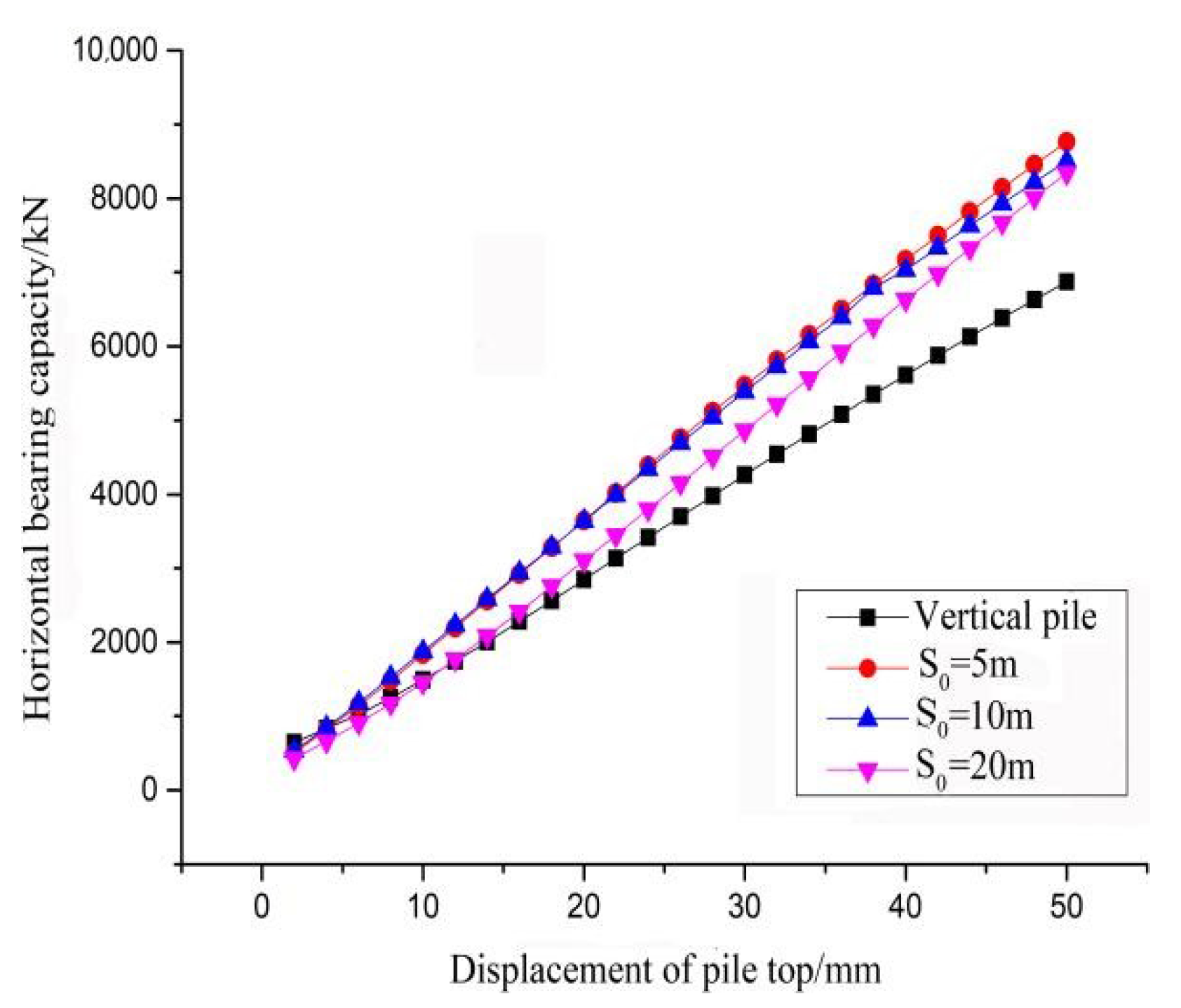
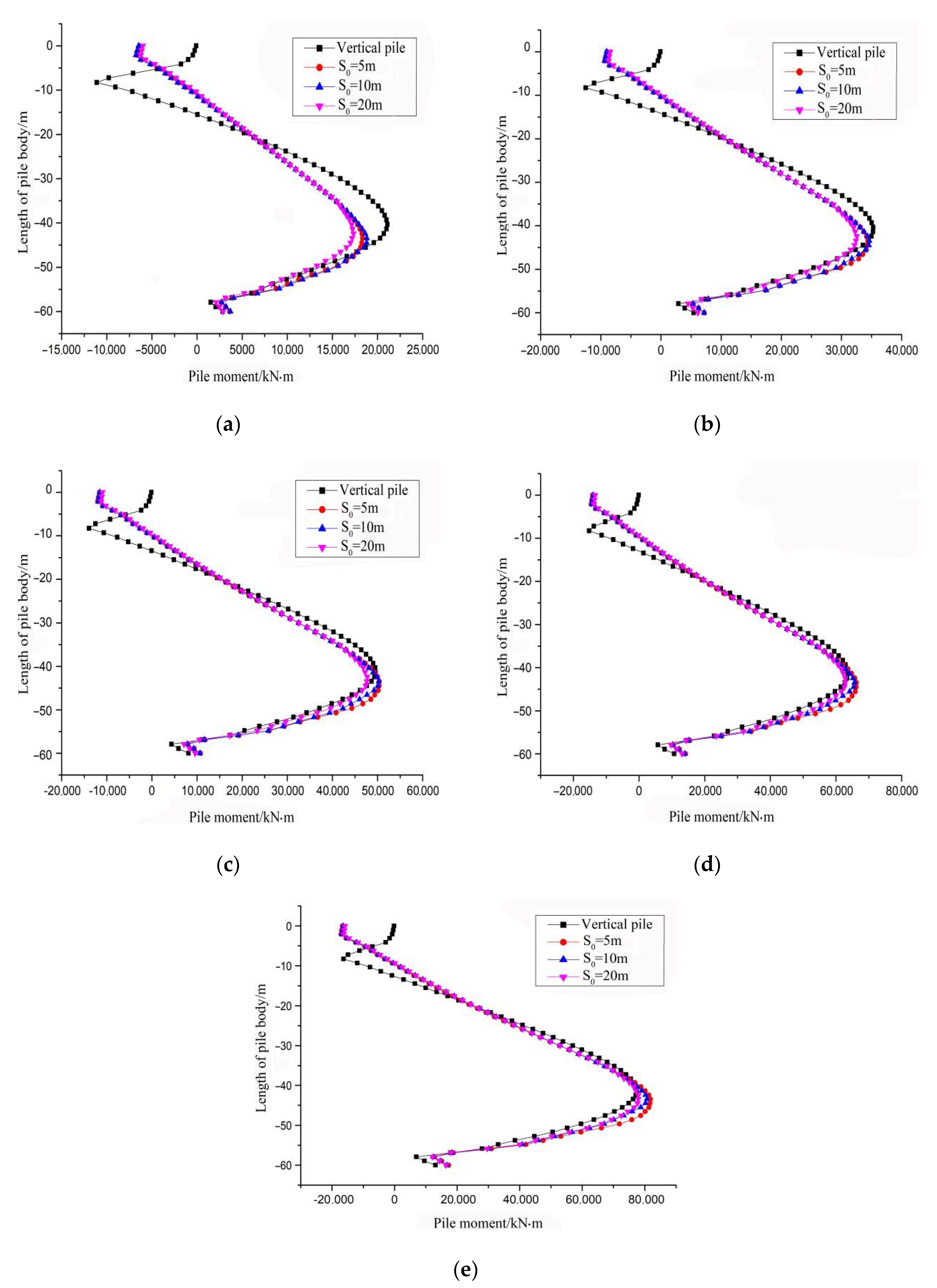
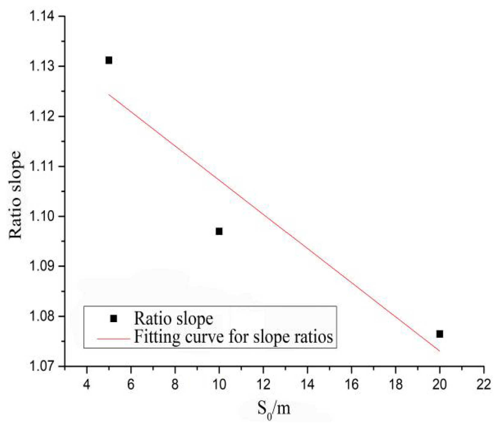
3.3.3. Comparative Analysis of Different Rubber Airbag Branch Buried Depths S0

Figure 7 and Figure 8 were derived by comparing the different working conditions of rubber airbag branch buried depth S0 values. It can be seen in Figure 7 that the maximum pile bearing capacities of 8767, 8502 and 8343 kN were obtained for the S0 values of 5, 10 and 20 m, respectively. It was concluded that deeper rubber airbag branches decreased pile bearing capacities. When pile top horizontal displacement was within 4 mm, straight pile bearing capacity was greater than that of the rubber airbag branch. Pile top horizontal displacement was within 18 mm and pile bearing capacity was smaller than that of the pile at a buried depth of rubber airbag branch at 5 m. It was seen that the soil reaction loss around the pile, due to different buried depths of rubber airbag branches, affected the improvement of pile horizontal bearing capacity.
By evaluating the effects of different buried depths of rubber airbag branches on pile bending moments, as shown in Figure 8, it was clearly seen that the bending moment of large-diameter pipe piles in the first and second inflection points appeared near the pile body of 5 and 8 m, respectively. However, the bending moment was changed in a relatively gentle trend after the first inflection point at 5 m of the rubber airbag branch pile. Analyses showed that the reason for the second turning point of a large-diameter pipe pile was that when the soil reaction around the pile increased with the depth, the rubber airbag branch pile and soil reaction around the pile resisted the pile top horizontal load under the action of the rubber airbag branch. Therefore, there were no obvious inflection points near the pile body of 8 m. From Figure 8a, it was concluded that the maximum bending moment of the rubber airbag branch was less than that of a large-diameter pipe pile at a pile top horizontal displacement of 10 mm. The maximum bending moment was slowly decreased with the increase in S0. Compared with Figure 8, the maximum bending moment of rubber airbag branch piles was lower than those of large-diameter pipe piles and the maximum bending moment was increased by increasing the pile top horizontal displacement. At a pile top horizontal displacement of 30 mm and with S0 values of 5 and 10 m, the maximum pile body bending moments were greater than those of large-diameter pipe piles. At a pile top horizontal displacement of 50 mm and with S0 values of 5 to 20 m, the maximum bending moments of the rubber airbag branch pile bodies exceeded those of the large-diameter pipe piles. However, from the overall curve change in the pile bending moment, the variation range of the rubber airbag branch pile curve is smaller, and the horizontal bearing performance of the rubber airbag branch pile is more stable than that of large-diameter pipe piles.

4. The Horizontal Bearing Capacity Characteristic Value of Rubber Airbag Branch Piles

4.1. Formula Correction for Bearing Capacity Characteristic Value of Large Diameter Tubular Piles

When there were no measured horizontal bearing capacities for single piles, the characteristic value of pile horizontal bearing capacity played an important role in engineering and it was still taken as important reference data in designs [17]. The equations of the horizontal bearing capacity characteristic value of a single pile are given in China’s existing standards. Using these equations, the horizontal bearing capacity of the rubber airbag branch pile was studied. The equation of the horizontal bearing capacity characteristic value is given in Equation (1):
R ha = 0.75 a 3 E I V x x 0 a ,   a = E I m b 0 5
where Rha is the horizontal bearing capacity characteristic value; “a” is the pile horizontal deformation coefficient; EI is pile bending stiffness; X0a is the allowable pile top horizontal displacement; Vx is the pile top horizontal displacement coefficient; m is the counterforce growth coefficient of horizontal foundation; b0 is the pile calculation width.
The above equation does not take into account pile exposed length. Generally, this equation can be applied for piles with short exposed lengths and pile diameters of less than 0.8 m, while large-diameter piles are employed for marine pile foundations [18,19]. Therefore, the applicability of the equation was verified by comparing the results obtained from the normative equation with numerical simulation results. The horizontal bearing capacities of small-diameter pipe piles with a pile length of 25 m, an outer diameter of 0.8 m and an inner diameter of 0.52 m were compared with the above-mentioned large-diameter pipe pile, as shown in Figure 9 and Figure 10. After analyzing relevant specifications, the value of “M” in the equation was taken as 600 MN/m4. After calculation, it can be seen in the figure that the normative equation was more suitable for pipe piles with short exposed lengths and small pile diameters, but not for large-diameter pipe piles.
Because of the limitations of the applicable scope of the normative equation, the exposed length L0 of a large-diameter pipe pile was taken as the most influential parameter. A correction factor was added to the canonical equation, as expressed in Equation (2):
ζ 1 = t L 0 3 + u L 0 2 + v L 0 + w
where L0 is the pile exposed length; t, u, v and w are undetermined coefficients; and ζ1 is the correction coefficient of the equation for large-diameter piles.
As shown in Figure 11, the variation in horizontal bearing capacities of large-diameter pipe piles with L0 values of 0, 5, 10, 15 and 20 m were analyzed in a pile top displacement range of 2–50 mm. It was seen from the figure that pile horizontal bearing capacity was linearly changed with the increase in pile top horizontal displacement. It was also seen from the figure that by increasing pile top horizontal displacement, the horizontal bearing capacity of the pile was changed almost linearly. By analyzing the difference between the calculated and simulated values, the variation law of the horizontal bearing capacity for large-diameter pipe piles with exposed length was derived. As shown in Figure 12, the relationship between the calculated value-simulated value ratio and pile exposed length was fitted; it was also seen that the error after fitting was lower and the values of undetermined coefficients t, u, v and w were obtained. The modified calculation equation of large-diameter pipe pile bearing capacity was stated as Equation (3).
R ha = ( 0.02 L 0 3 + 1.28 L 0 2 31 . 47 L 0 + 353.19 ) × 10 3 × 0.75 a 3 E I V x x 0 a
Characteristic, simulated and modified normative values of large-diameter pipe piles bearing capacity were compared at L0 values of 0, 4, 12 and 20 m. As shown in Figure 13, it can be seen that the modified characteristic value of horizontal bearing capacity of large-diameter pipe piles was reasonable.

4.2. The Characteristic Value of Bearing Capacity for Large-Diameter Rubber Airbag Branch Piles

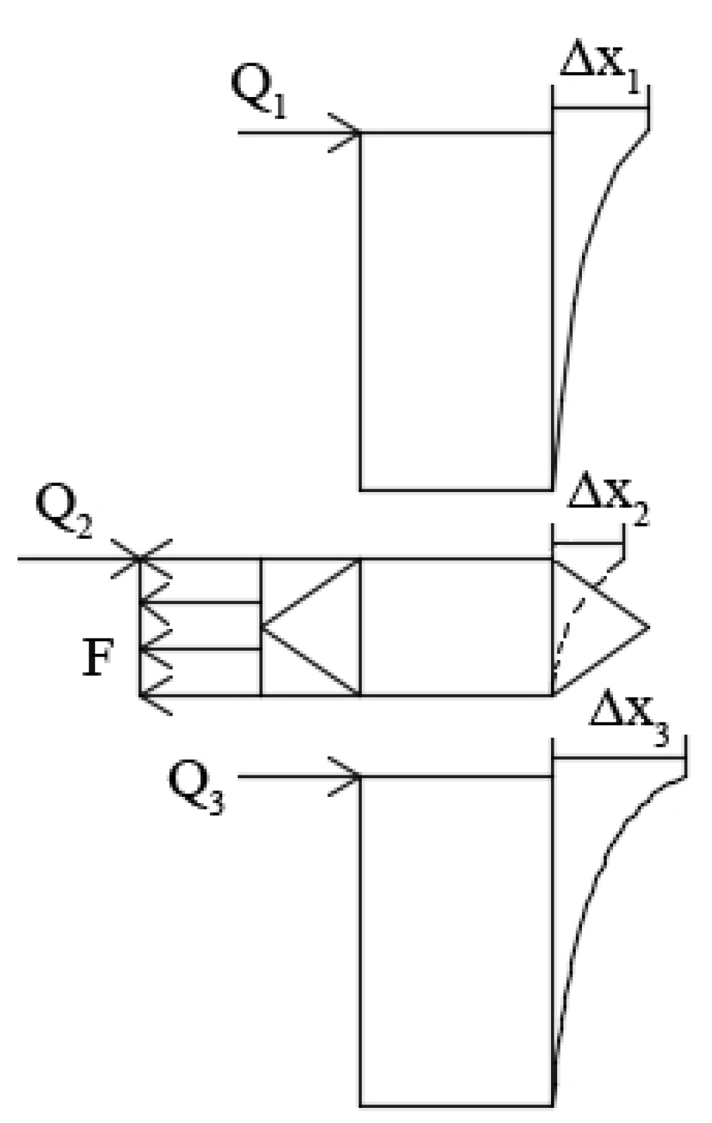
4.2.1. The Equation of the Resistance of Horizontal Load for Rubber Airbag Branch Piles

Vacuum negative pressure was mainly generated due to soil density as well as a cohesive force and suction force among water molecules. The resistance to a horizontal load due to a rubber airbag branch pile lateral displacement in clay was similar to the processes of drainage and consolidation in low-permeable soils, which required great suction forces to discharge. Refs. [20,21,22] In this section, negative vacuum pressure and horizontal resistance due to negative friction force were adopted as the main reference forces. In addition, the following assumptions were made: rubber airbag branch pile tension was in the form of small deformation; at a pile top displacement of 0, the rubber airbag branch did not play a role and F was considered to be 0; the soil was uniform and atmospheric pressure inside the soil was not changed by the depth and remained at a constant value. The equations of the horizontal resistance of the rubber airbag branch pile were derived as presented in Equations (4)–(6):
F = F 1 + 2 F 2
F 1 = P ( R + r ) h 2
F 2 = k γ h tan α + c tan ψ = k γ h tan δ + c h / ( R + r )
where F is the resultant force of negative vacuum pressure and horizontal friction; F1 is negative vacuum pressure; F2 is horizontal friction; P is pressure; R is the outer radius of the rubber airbag branch; r is pile radius; h is the rubber airbag branch dish height; ψ is the rubber airbag branch horizontal plane and surface projection angle, ψ = arctan[h/(R + r)]; k is the coefficient of soil side pressure, k = υ/(1 + υ); υ is Poisson’s ratio; γ is the soil weight, take the value of 19.23 kN/m3; δ is the soil internal friction angle, take the value of 14; c is the soil mass cohesive force, take the value of 25 kN/m2. Other coefficients can be obtained from the text or conversion.

4.2.2. Establishment of the Characteristic Value of Horizontal Bearing Capacity

The rubber airbag branch pile was found to be similar to the variable section pile and could be divided into different sections based on the position of the rubber airbag branch pile installed in the pile. However, rubber airbag branch rigidity was greatly different from pile rigidity and therefore, an equivalent substitution method could not be applied for making the equivalent substitution between the rubber airbag outside radius and pile diameter. Therefore, in this section, it was assumed that the foundation reaction coefficient did not change with the pile depth and deformation at the divided pile section, which could be continuous without additional stress. By assuming the displacement and rotation angle of the rock-socketed pile bottom to be zero, the rubber airbag branch horizontal force acted on the pile body in the form of the resultant force. Employing boundary conditions at the pile bottom, a backward calculation method was developed. A single rubber airbag branch pile was divided into three sections, as shown in Figure 14. Similarly, when the pile body acted on n rubber airbag branches, its amplitude was divided into 2n + 1 sections. Under the action of horizontal load, the shear force transferred along the pile body and created a horizontal displacement and the pile section at the rubber airbag branch received a reverse horizontal resultant force of F. The equations of single branch and n branches were established as Equations (7) and (8).
Q 1 + Q 2 + Q 3 F = ξ 1 ξ 2 ξ 3 × 0.75 a 3 E I V x ( Δ x 1 + Δ x 2 + Δ x 3 )
Q 1 + Q 2 + + Q 2 n + 1 n F = ξ 1 ξ 2 ξ 3 × 0.75 a 3 E I V x ( Δ x 1 + Δ x 2 + Δ x 2 n + 1 )
where i = 0 n Q 2 n + 1 is the pile horizontal bearing capacity with n rubber airbag branches; i = 0 n Δ x 2 n + 1 is the pile top horizontal displacement with n rubber airbag branches, (n = 0, 1, 2, 3, …); and ζ2 and ζ3 are correction factors related to pile exposed length L0 and rubber airbag branch buried depth S0 in the equation of rubber airbag branch pile, respectively. Other parameters are the same as above.
The calculation and simulation values of the horizontal bearing capacity of the rubber airbag branch pile are compared. By applying the slope ratio method, as shown in Figure 15 and Figure 16, the ζ2 and ζ3 correction coefficients could be obtained, as stated in Equations (9) and (10), respectively.
ζ 2 = ( 0.112 L 0 3 4.38 L 0 2 + 32.23 L 0 + 1058.89 ) / 10 3
ζ 3 = 3.42 × 10 3 S 0 + 1.14
where S0 is the rubber airbag branch pile’s buried depth.

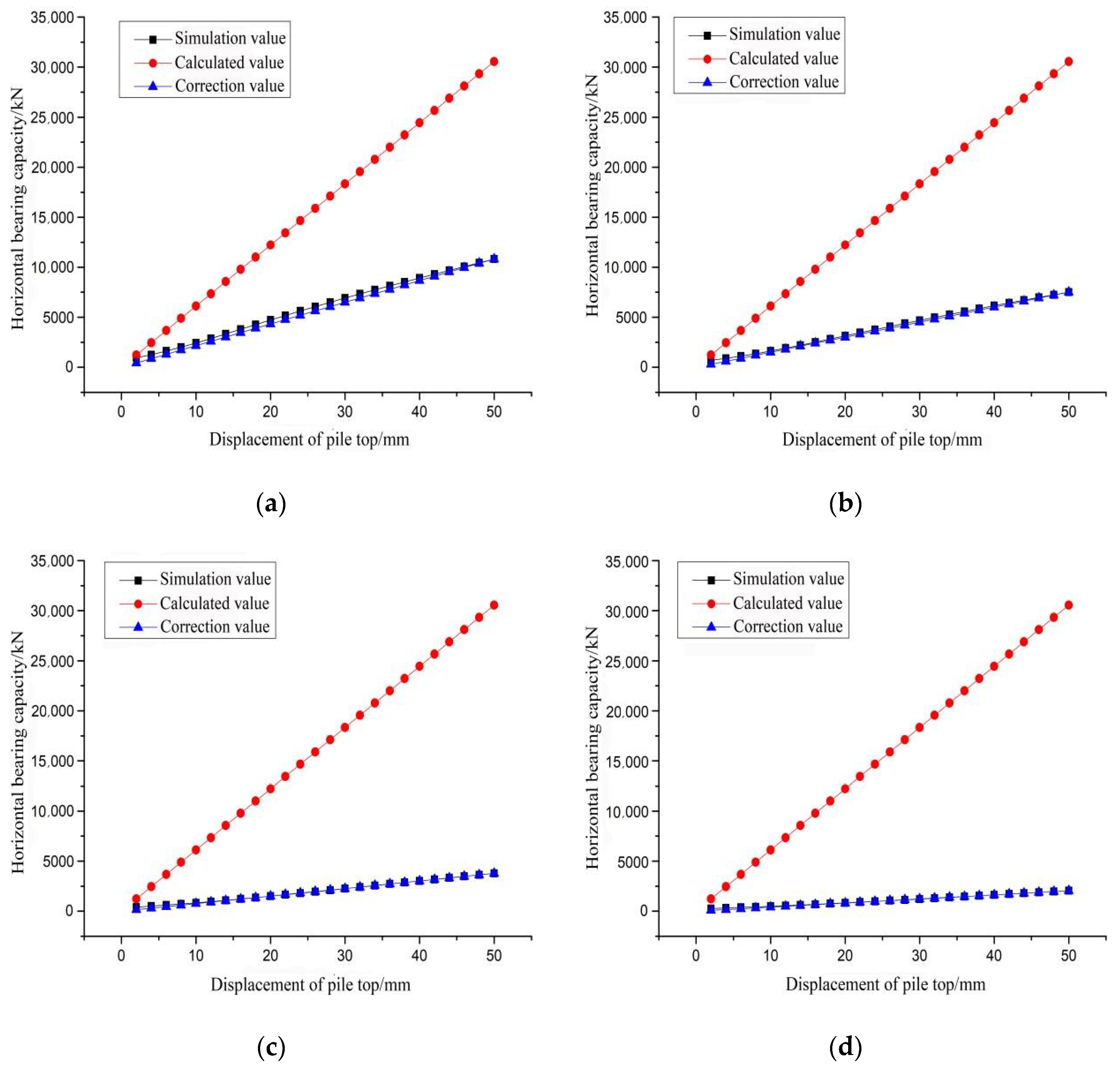
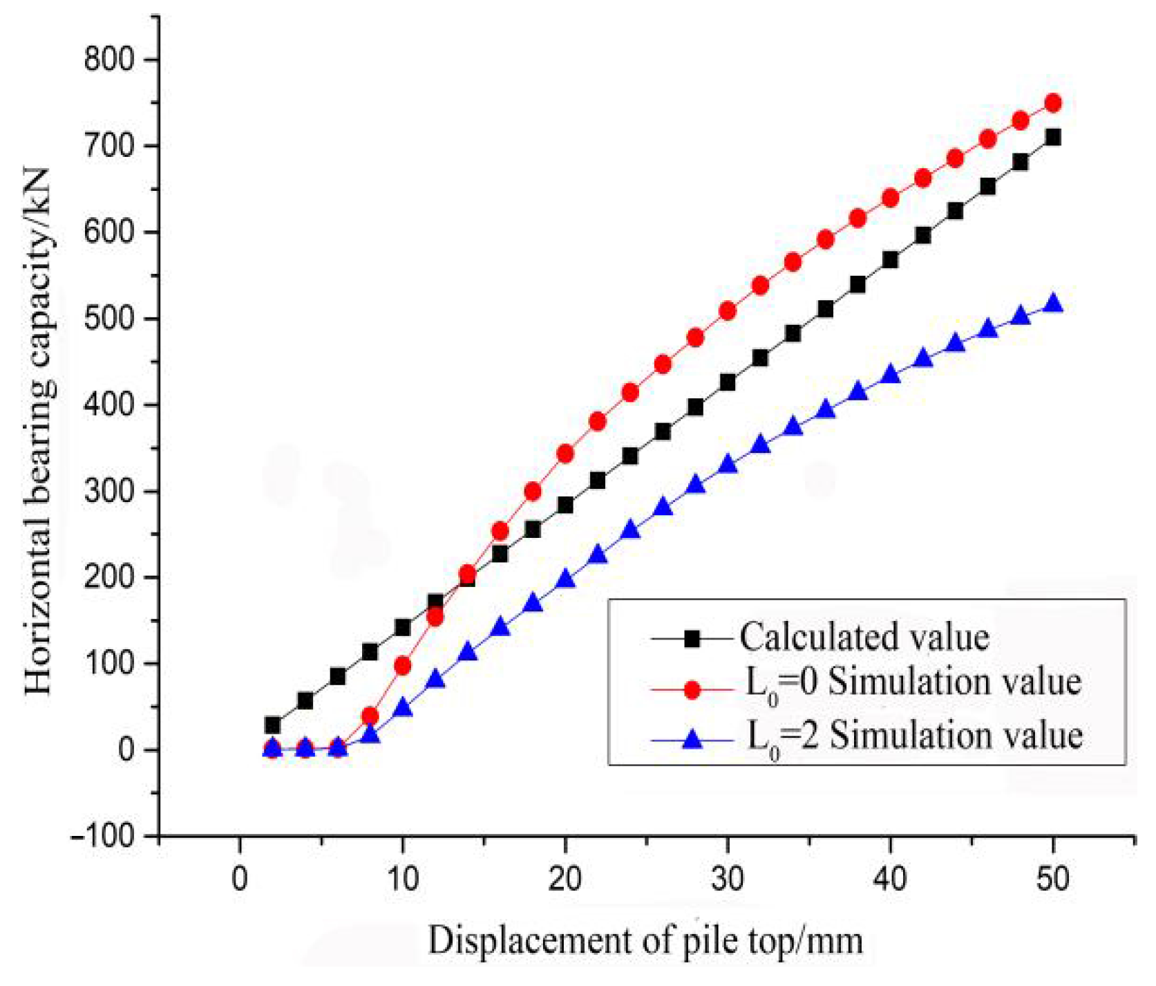
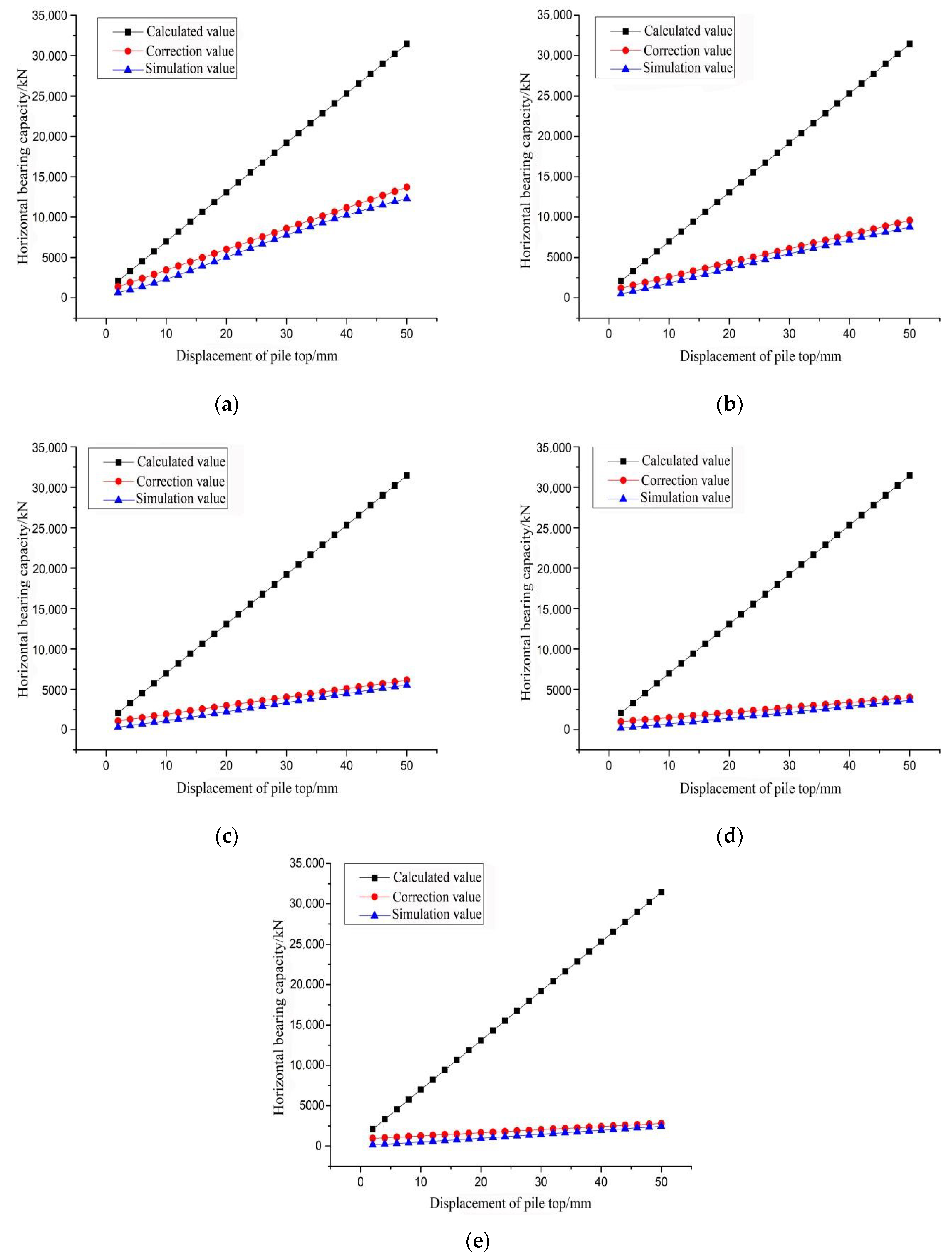
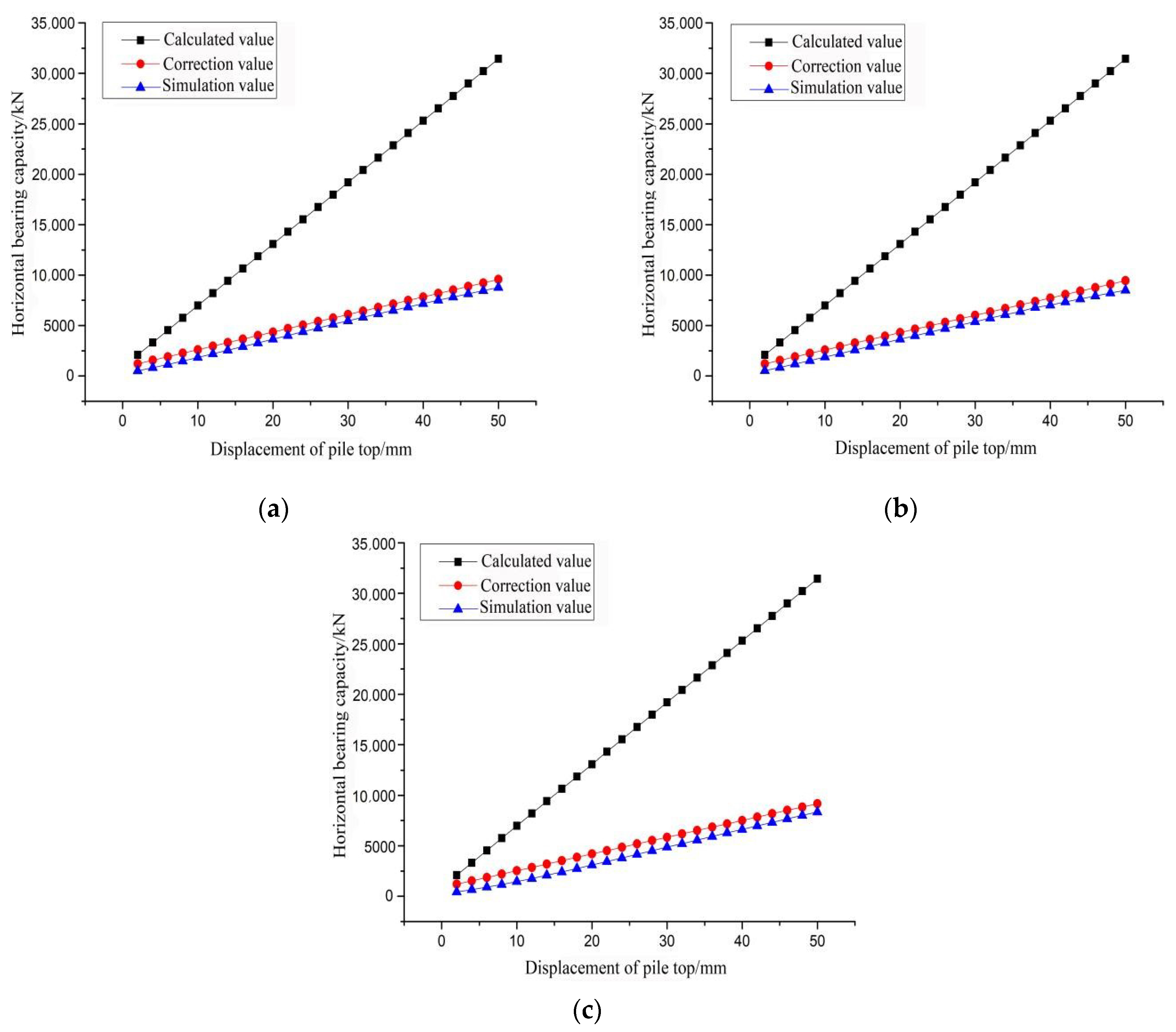
4.3. Verification of Bearing Capacity Eigenvalue Equation of Rubber Airbag Branch Pile

According to the working conditions described in Table 2 and Table 3, calculated and simulated horizontal bearing capacity characteristic values before and after modification were compared and analyzed, as shown in Figure 17 and Figure 18. It can be seen from the figure that, at a pile top horizontal displacement of 50 mm and with L0 values of 0, 5, 10, 15 and 20 m, the differences between corresponding, uncorrected, calculated, and simulated values were 19,100, 22,663, 25,881, 27,802 and 28,978 kN, and those between the corrected, calculated, and simulated values were 1389, 803, 588, 378 and 351 kN, respectively. At S0 values of 5, 10 and 20 m, the corresponding differences were 22,663, 21,992 and 23,087 kN, respectively. The differences between the modified calculated and simulated values were 803, 936 and 830 kN, respectively. By analyzing the difference values, the corrected calculated values were found to be close to the simulated values and the corrected error was controlled within the range of 10%. Due to the complexity of soil mass’ physical and mechanical parameters, there were too many influencing factors, making it impossible to accurately calculate the contact force between the pile–soil and rubber airbag branch pile–soil mass interfaces. Moreover, the correction coefficient of fitting ζ1, ζ2, ζ3 had certain errors. By multiplying corrected coefficients ζ1, ζ2 and ζ3, the overall error was amplified and it was concluded that the horizontal bearing capacity characteristic value of the modified rubber airbag branch pile was greater than the simulated value. However, a comparison of the calculation and comparison results revealed that the calculated values after the addition of the correction coefficients ζ2 and ζ3 were closer to the simulation values, and their accuracy was higher than the calculated values before adding correction coefficients, which played a certain role in the accuracy of the calculation results.

5. Conclusions

Using the ABAQUS numerical simulation software, a rubber airbag branch pile with a diameter of 5 m was developed to combine the pile exposed length and different pile top horizontal displacements to explore the horizontal bearing performance of piles. The relationship between pile top horizontal displacement and pile horizontal bearing capacity was also investigated under different rubber airbag branch sizes and soil buried depths. The following conclusions were made:
(1)
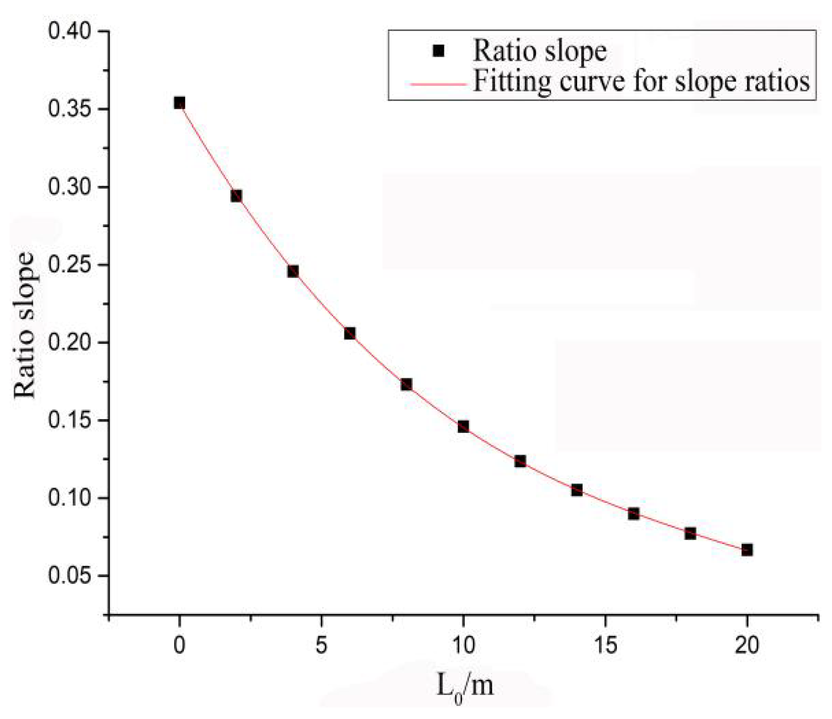
The horizontal bearing capacities of piles with large pile top displacements were obviously higher than those of the pipe piles under the action of a rubber airbag branch bearing tray, which indicated that the rubber airbag branch bearing had a transverse constraint on the pile. As L0 was increased, pile horizontal bearing capacity was also rapidly decreased.
(2)
The increase in the rubber airbag branch height and radius did not increase pile horizontal bearing capacity, however, an increase in pile top horizontal displacement enhanced the increase rate of horizontal bearing capacity compared to that of the large-diameter pipe piles. Under the lateral constraint of the rubber airbag branch pile, the reverse displacement position and reverse pile bending moment were decreased and pile horizontal bearing capacity was more stable.
(3)
A buried depth of rubber airbag branch also increased pile horizontal bearing capacity. The horizontal bearing capacity was increased with an increase in the buried depth from 5 to 10 m.
(4)
The equation for the rubber airbag branch bearing capacity characteristic value was also derived. After modification, the modified equation of the horizontal bearing capacity characteristic value of the rubber airbag branch pile could be applied as a reference in designs.

Author Contributions

Methodology, X.W.; software, Z.W.; validation, X.W., Z.W. and C.Y.; formal analysis, Z.W.; investigation, Z.W.; resources, C.Y.; data curation, Z.W.; writing—original draft preparation, Z.W.; writing—review and editing, X.W.; visualization, C.Y.; supervision, C.Y.; project administration, L.L. All authors have read and agreed to the published version of the manuscript.

Funding

China Youth Science Foundation Project, 51708317.

Data Availability Statement

The data presented in this study are available on request from the corresponding author. The data are not publicly available due to the follow-up research.

Conflicts of Interest

The authors declare no conflict of interest.

References

  1. Doherty, P.; Gavin, K. Laterally loaded monopile design for offshore wind farms. Proc. ICE-Energy 2011, 165, 7–17. [Google Scholar] [CrossRef] [Green Version]
  2. Kim, Y.; Jeong, S. Analysis of soil resistance on laterally loaded piles based on 3D soil-pilin-teraction. Comput. Geotech. 2010, 38, 248–257. [Google Scholar] [CrossRef]
  3. Nghiem, H.M.; Chang, N.-Y. Pile under torque in nonlinear soils and soil-pile interfaces. Soils Found. 2019, 59, 1845–1859. [Google Scholar] [CrossRef]
  4. Wang, H.; Yao, J.; Liu, L. The Application of ANSYS in the Horizontal Bearing Pile. Appl. Mech. Mater. 2014, 193–194, 935–938. [Google Scholar] [CrossRef]
  5. Edro-Tomislav Simic-Silva, B.M.; Simic, D. 3D simulation for tunnelling effects on existing pile. Comput. Geotech. 2020, 124, 67–82. [Google Scholar]
  6. Jeong, S.; Kim, Y. Analysis for Laterally Loaded Offshore Piles in Marine Clay. Geotech. Eng. J. SEAGS AGSSEA 2020, 51, 326–342. [Google Scholar]
  7. Mahdi, T.K.; Al-Neami, M.A.; Rahil, F.H. Experimental and Numerical Study on the Winged Pile-Soil Interaction under Lateral Loads. In IOP Conference Series: Earth and Environmental Science; IOP Publishing: Bristol, UK, 2022; Volume 961, pp. 151–165. [Google Scholar]
  8. Aysan, P.; Mahzad, E.F.; Hooshang, K. Pile-soil interaction determined by laterally loaded fixed head pile group. Geomech. Eng. 2021, 26, 13–25. [Google Scholar]
  9. González, F.; Padrón, L.A.; Aznárez, J.J.; Maeso, O. Equivalent linear model for the lateral dynamic analysis of pile foundations considering pile-soil interface degradation. Eng. Anal. Bound. Elem. 2020, 119, 59–73. [Google Scholar] [CrossRef]
  10. Djillali, A.B. Analytical Quantification of Ultimate Resistance for Sand Flowing Horizontally around Monopile: New p-y Curve Formulation. Int. J. Geomech. 2021, 21, 319–335. [Google Scholar]
  11. Rathod, D.; Muthukkumaran, K.; Sitharam, T.G. Effect of Slope on p-y Curves for Laterally Loaded Piles in Soft Clay. Geotech. Geol. Eng. 2018, 36, 1509–1524. [Google Scholar] [CrossRef]
  12. Zhai, E.; Xu, H.; Guo, S.; Jin, H.; Du, X. Comparative study on horizontal bearing characteristics of offshore wind pipe pile foundation in xiangshu. Acta Sol. Sin. 2019, 40, 681–686. [Google Scholar]
  13. Sahli, A.; Alouach, M.A.K.; Sahli, S.; Karas, A. Reliability techniques and Coupled BEM/FEM for interaction pile-soil. Recl. Mécanique 2017, 2, 112–124. [Google Scholar]
  14. Li, Y.M.; Ma, Y.H.; Zhao, G.F.; Zhou, F.L. Experimental Study on the Effect of Alternating Ageing and Sea Corrosion on Laminated Natural Rubber Bearing’s Tension-shear Property. J. Rubber Res. 2020, 23, 151–161. [Google Scholar] [CrossRef]
  15. Cherezova, E.N.; Karaseva Yu, S.; Momzyakova, K.S. Hydrophilic Rubber Based on Butadiene–Nitrile Rubber and Phytogenic Powdered Cellulose. Polym. Sci. Ser. D 2022, 15, 118–121. [Google Scholar] [CrossRef]
  16. Hu, Y.; Lu, Z.; Zhai, Q.; Zhang, Y. Discussion on p-y curve of large diameter and wing pile in soft clay. Water Conserv. Hydropower Technol. 2018, 49, 143–152. [Google Scholar]
  17. Zhang, Z.; Guan, P.; Xu, J.; Wang, B.; Li, H.; Dong, Y. Horizontal Loading Performance of Offshore Wind Turbine Pile Foundation Based on DPP-BOTDA. Appl. Sci. 2020, 10, 492. [Google Scholar] [CrossRef] [Green Version]
  18. Zhai, Q.; Xiang, W.; Li, Y. Study on the Lateral Deformation of the Flexible Berthing Pile of High-Pile Wharf under Ship Impact Load. Appl. Mech. Mater. 2015, 3843, 1184–1187. [Google Scholar] [CrossRef]
  19. Zhao, M.; Jiang, C.; Cao, W.; Liu, J. Catastrophic model for stability analysis of high pile-column bridge pier. J. Cent. South Univ. Technol. 2007, 14, 725–729. [Google Scholar] [CrossRef]
  20. Bergado, D.T.; Pitthaya, J.; Pornkasem, J.; Suched, L.; Chartchai, P.; Nuttapong, K.; Francisco, B. Case study and numerical simulation of PVD improved soft Bangkok clay with surcharge and vacuum preloading using a modified air-water separation system. Geotext. Geomembr. 2022, 50, 137–153. [Google Scholar] [CrossRef]
  21. Almeida, M.S.S.; Deotti, L.O.G.; Almeida, M.C.F.; Marques, M.E.S.; Cardoso, I.M. Vacuum Preloading on Structured Clay: Field, Laboratory, and Numerical Studies. Int. J. Geomech. 2021, 21, 362–376. [Google Scholar] [CrossRef]
  22. Apriadi, D.; Barnessa, R.A.; Marsa, N.A.I. Finite Element Study of Vacuum Preloading and Prefabricated Vertical Drains Behavior for Soft Soil Improvement. J. Tek. Sipil 2019, 26, 189. [Google Scholar] [CrossRef] [Green Version]
Figure 1. (a) Schematic diagram of rubber airbag branch pile; (b) plan of rubber airbag branch.
Sustainability 14 07331 g001
Figure 2. (a) Pile grid division; (b) rubber airbag branch grid division; (c) component grid division.
Sustainability 14 07331 g002
Figure 3. (a) 0 m external exposure of pile L0; (b) 5 m external exposure of pile L0; (c) 10 m external exposure of pile L0; (d) 15 m external exposure of pile L0; (e) 20 m external exposure of pile L0.
Sustainability 14 07331 g003
Figure 4. Influence of rubber airbag branch height on horizontal bearing capacity of pile.
Sustainability 14 07331 g004
Figure 5. (a) 10 mm pile top horizontal displacement; (b) 20 mm pile top horizontal displacement; (c) 30 mm pile top horizontal displacement; (d) 40 mm pile top horizontal displacement; (e) 50 mm pile top horizontal displacement.
Sustainability 14 07331 g005
Figure 6. The influence of the outer radius of rubber airbag branch on horizontal bearing capacity.
Sustainability 14 07331 g006
Figure 7. Influence of buried depth S0 of rubber airbag branch on bearing capacity.
Sustainability 14 07331 g007
Figure 8. (a) 10 mm horizontal pile top displacement; (b) 20 mm horizontal pile top displacement; (c) 30 mm horizontal pile top displacement; (d) 40 mm horizontal pile top displacement; (e) 50 mm horizontal pile top displacement.
Sustainability 14 07331 g008
Figure 9. Comparison of horizontal bearing capacities of small-diameter pipe piles.
Sustainability 14 07331 g009
Figure 10. Comparison of horizontal bearing capacities of large-diameter pipe piles.
Sustainability 14 07331 g010
Figure 11. Horizontal bearing capacity of large-diameter pipe piles with different exposed lengths.
Sustainability 14 07331 g011
Figure 12. ζ1 fitting correction coefficients.
Sustainability 14 07331 g012
Figure 13. (a) 0 m external pile exposure; (b) 4 m external pile exposure; (c) 12 m external pile exposure; (d) 20 m external pile exposure.
Sustainability 14 07331 g013
Figure 14. Diagram of force exerted on rubber capsule branch.
Sustainability 14 07331 g014
Figure 15. ζ2 fitting correction coefficient.
Sustainability 14 07331 g015
Figure 16. ζ3 fitting correction coefficient.
Sustainability 14 07331 g016
Figure 17. (a) 0 m external pile exposure; (b) 5 m external pile exposure; (c) 10 m external pile exposure; (d) 15 m external pile exposure; (e) 20 m external pile exposure.
Sustainability 14 07331 g017
Figure 18. (a) 5 m burial depth of rubber airbag branch; (b) 10 m burial depth of rubber airbag branch; (c) 20 m burial depth of rubber airbag branch.
Sustainability 14 07331 g018
Table 1. Physical parameters of each component [16].
ModulusPoisson RationCohesionSevereInternal Friction Angle
Clay layer30 MPa0.325 kPa19.23 kN/m14°
Rock stratum400 GPa0.3——27 kN/m——
Rubber airbag branch10 MPa0.3——10 kN/m——
Pile38 GPa0.3——25 kN/m——
Table 2. Combination of different lengths of exposed pile.
R (m)Height (m)S0 (m)L0 (m)
5250/5/10/15/20
Table 3. Combination of different heights.
R (m)Height (m)S0 (m)L0 (m)
51/1.5/255
Table 4. Combination of different rubber airbag branch outer radius conditions.
R (m)Heigh (m)S0 (m)L0 (m)
3.125/3.75/5255
Table 5. Combination of different outer radius conditions.
R (m)Height (m)S0 (m)L0 (m)
525/10/205
Publisher’s Note: MDPI stays neutral with regard to jurisdictional claims in published maps and institutional affiliations.

